Article

Controllable Micro-Particle Rotation and Transportation Using Sound Field Synthesis Technique

1
State Key Laboratory of Fluid Power and Mechatronic Systems, School of Mechanical Engineering, Zhejiang University, 38 Zheda Road, Hangzhou 310027, China
2
State Key Laboratory for Strength and Vibration of Mechanical Structures, School of Aerospace Engineering, Xi’an Jiaotong University, 28 West Xianning Road, Xi’an 710049, China
3
School of Mechanical and Automatic Control, Zhejiang Sci-Tech University, Hangzhou 310018, China
4
School of Engineering, Qufu Normal University, Rizhao 276825, China
*
Authors to whom correspondence should be addressed.
Appl. Sci. 2018, 8(1), 73; https://doi.org/10.3390/app8010073
Submission received: 4 December 2017 / Revised: 26 December 2017 / Accepted: 3 January 2018 / Published: 8 January 2018
(This article belongs to the Section Acoustics and Vibrations)

Abstract

:
Rotation and transportation of micro-particles using ultrasonically-driven devices shows promising applications in the fields of biological engineering, composite material manufacture, and micro-assembly. Current interest in mechanical effects of ultrasonic waves has been stimulated by the achievements in manipulations with phased array. Here, we propose a field synthesizing method using the fewest transducers to control the orientation of a single non-spherical micro-particle as well as its spatial location. A localized acoustic force potential well is established and rotated by using sound field synthesis technique. The resultant acoustic radiation torque on the trapped target determines its equilibrium angular position. A prototype device consisting of nine transducers with 2 MHz center frequency is designed and fabricated. Controllable rotation of a silica rod with 90 μm length and 15 μm diameter is then successfully achieved. There is a good agreement between the measured particle orientation and the theoretical prediction. Within the same device, spatial translation of the silica rod can also be realized conveniently. When compared with the existing acoustic rotation methods, the employed transducers of our method are strongly decreased, meanwhile, device functionality is improved.

1. Introduction

Contactless rotation of cells and micro-organisms is indispensable in cell analysis and biology engineering [1,2,3,4,5,6]. For example, controlling the cellular orientation is used to help understand how the acini is formed by normal cells, which is a fundamental question in the formation and decay of multicellular architecture [5]. In malaria diagnosis, rotation analysis of the cellular sample is employed to improve the inspection efficiency, by which the infected sample can be easily identified by the rotation speed difference from the normal one [6]. In the engineering field, effective changing of the angular positions of micro- or nano-wires, reinforcing fiber, and micro-component, is always expected for the composite material manufacture [7,8] and microsystems assembly [9,10]. Different field effects generating from optical, electric, magnetic, and acoustic have been demonstrated to possess the ability of contactless manipulating micro-objects [11,12,13,14]. Among these methods, the acoustic field shows outstanding features in the forms of biocompatibility, miniaturized excitation facility, low system cost, and no requirement for the targets’ optical, magnetic, or charge properties [15,16]. The non-contact trapping, separation, agglomeration, and patterning of micro-objects or anisotropic particles using the momentum effects of acoustic waves, namely the acoustic radiation force, have attracted increasing interests [16,17,18,19,20,21,22]. Dexterous manipulation of micro-particles have been realized by precursor swirling Rayleigh waves and 16-element, 64-element, or more elements transducer arrays recently [18,23,24,25,26]. However, the huge elements number of the transducer array makes the system quite complex and non-affordable for the extended application.
Acoustic vortex with the rotating phase around its propagating axis also carries angular momentum, and can be used to rotate micro-particle [27,28]. When it interacts with a scatterer, acoustic torque will be induced on the object. Continuous rotation of tile, syringe and other axisymmetric objects has been realized using acoustic vortex beam that is generated by thermoacoustic or individually addressed transducers [28,29,30,31,32]. Another way to rotate the micro-particle is employing the viscous torque resulted from the acoustic streaming in the viscous boundary layer around the particle [33,34,35]. The above-mentioned two methods are applicable to continuous rotation, especially spherical object, but are unable to stop at certain angular position [27,28,33,34,35].
For non-spherical particles, unbalanced acoustic radiation pressure on the surface may also induce an acoustic radiation torque depending on its angular position relative to the sound field [36,37]. Besides the conventional vortex-based rotation, controlling the object orientation is also achievable with this kind of acoustic torque. Changing the orientation of the sound field, by the manner of mechanically shifting the wave direction or modulating the wave parameters (amplitude or frequency), the fibers, and other non-spherical particles will be driven to rotate and finally reach an equilibrium angular position [38,39,40,41,42,43,44]. However, the resolution and controllability are limited for these demonstrated methods. For the method adjusting the propagation direction of standing wave with alternate excitation of several pairs of opposed transducers, the particle could only rotate like a step motor and the step angle 180°/N is limited by the number of transducer pairs N [38,39]. Particle rotation based on phase or frequency modulation strongly relies on the resonant modes of the employed acoustic chambers. So, the chamber should be elaborately designed with a proper Q-factor, which increases the system complexity and cost [38,40,41,42,43]. In addition, it is difficult to maintain the rotation speed due to the amplitude variations of different modes. Amplitude modulation, which rotates the particle by varying the amplitude ratio of incident waves, causes the fluctuations of radiation force strength and the corresponding constraint ability. As a result, the particles are easy to drift in the rotation process [38,44]. Besides the above limitations, the desired sound fields in these methods are always filled with the whole device, which is not satisfying for rotating single particle or independently manipulate multiple particles [45].
Changing the orientation of a target sound field can be treated as generating a series of sound fields only with azimuth variations at different times. It is well known that sound field synthesis technique has the ability to produce any required sound field within a given region by imposing the required pressure on the region boundary [45,46,47]. Hence, this technique can be implemented multiple times to generate a rotating sound field. It is convenient to impose the required boundary pressure by adjusting the amplitude and phase of several transducers, and then the micro-particle can be rotated by the radiation torque with higher flexibility.
In this study, controlling the orientation and spatial location of a non-spherical micro-particle by synthesized sound field is proposed, where the fewest transducers are to be employed. The working principle is firstly introduced with a detailed description of the employed sound field synthesis technique. The rotating and transporting transformation of the desired field, which determines the particle orientation and position, is theoretically demonstrated. To validate the proposed method, the prototype device is developed. Calibration of the employed transducers is performed before measuring the synthesized and transformed sound field. Finally, a silica rod is used as the target to perform the experiment.

2. Method

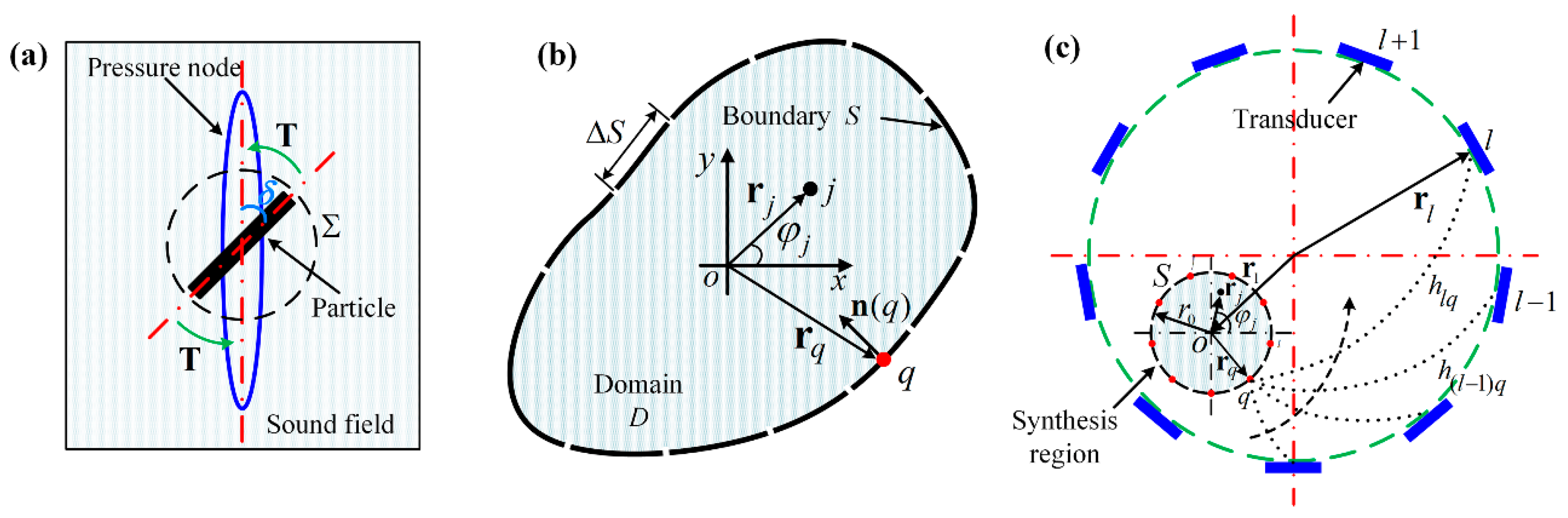
2.1. Mechanical Effects on Microparticles in a Sound Field

It has been well demonstrated that micro-particles suspended in a sound field will be stably trapped at certain positions. A time-averaged acoustic radiation force, which arises from the second-order effects of the incident and scattered waves, constrains the target in the force potential minimum. For less compressible micro-particle that is adopted in this paper, the stable force potential minimums always correspond to the pressure nodes. Correspondingly, the particle position is related to the spatial location of pressure node
( x c , y c ) = ( x s , y s ) | min ( P ) ,
where ( x s , y s ) | min ( P ) indicates the position with minimum sound pressure. Since the sound pressure P ( x s , y s ) is also a function of the source frequency, amplitude and phase, the node position is only determined when these parameters are set. Then the trajectories of the micro-particles can be easily predicted by the movement of the acoustic pressure nodes.
When considering the non-spherical particles, even if the sound field does not contain any acoustic vortices, an additional torque may be induced due to the asymmetric distribution of the acoustic radiation pressure on the particle surface. Theoretical calculation of the acoustic radiation torque on a rigid rectangular disk was first proposed by Maidanik, in which the general expression was derived by an approach analogous to the radiation force [36]. Nowadays, the theory has been further developed with the influence of particle shape and material [37,38,39,40,44,48].
When the dissipation in the wave propagating process can be neglected, the acoustic radiation torque on an irregularly shaped scatterer can be expressed by the time-averaged flux of angular momentum through any surface enclosing the particle [48], as shown in Figure 1a,
T i = Σ ε i j k r j Π k l n l d S ,
where the angle brackets indicate the time-averaged operation, i , j , and k denote the Cartesian axes, Σ is the integral surface, n l is the outward normal of Σ , ε i j k is the permutation tensor, r j is a position vector from the integral unit to the coordinate origin, and Π k l is the tensor of momentum flux density. Unlike the torque from the orbital angular momentum that is associated with acoustic vortex, this acoustic torque on the scatterer is dependent on the angle position [49]. Accordingly, the scatterer will be rotated and finally stopped at the certain angular position where the acoustic radiation torque is zero.
The acoustic medium (water) in this study can be regarded as an ideal fluid since its viscous boundary layer ξ = υ / π f 0.3 μm is much smaller than the object (90 μm in length and 15 μm in diameter r) [50,51,52]. The particle to be manipulated has the stiffness and density larger than the medium. As proposed by Thomas et al. [38,44] and Kun et al. [53], a stripe-shaped particle satisfying the above conditions would be trapped at the pressure node and rotated to a specific angular position. If the contours of acoustic pressure around the particle also have the stripe shape, the major axis of the stripe-shaped particle will coincide with that of the contours around the pressure node. Thus, the particle will always follow the rotation of the sound field and the rotation angle ϕ of target particle equals to that of the sound field
ϕ = δ ,
where δ is the rotation angle of the sound field as illustrated in Figure 1a. Theoretically, the particle can be controlled with any orientation compared with its initial angle.

2.2. Synthesizing the Required Pressure Field by Finite Control Points

For simplicity, here we only consider the two-dimensional (2D) domain problem and it is convenient to extend our method to the three-dimensional (3D) case. In a fluid medium without any body forces (Figure 1b), the acoustic pressure within an arbitrarily shaped domain D is related to the pressure and velocity on the boundary S as described by Kirchhoff–Helmholtz integral equation [54]. Discretizing the boundary into N elements, the pressure p at any location r j within D can be given by
p ( r j ) = q = 1 N ( p ( r q ) G ( r q , r j ) n ( r q ) G ( r q , r j ) p ( r q ) n ( r q ) ) Δ S q ,
where r q , n ( r q ) , and Δ S q indicate the center position, normal direction, and length of the qth boundary element, respectively. G ( r q , r j ) , the free-space Green’s function, which represents the wave emitted from a point source located at r q and measured at location r j in a free space, has the following form
G ( r k , r j ) = i 4 H 0 ( 1 ) ( k r k r j ) ,
where H 0 ( 1 ) ( ) is the zero order Hankel function of the first kind, k = 2 π / λ is the wavenumber, λ is the wavelength of the incident wave, i is the imaginary unit, and is the operator of Euclidean distance.
When r j is located on the boundary S , the Kirchhoff–Helmholtz equation becomes [54]
1 2 p ( r j ) = q = 1 N ( p ( r q ) G ( r q , r j ) n ( r q ) G ( r q , r j ) p ( r q ) n ( r q ) ) Δ S q .
Then, the normal derivative of p ( r q ) can be expressed by the pressure on the boundary elements. Combining Equations (4) and (6), we can see that p ( r j ) is only determined by the pressure of the discretized boundary elements. For equally discretized boundary elements, when the interval between the adjacent element centers satisfies Nyquist condition, the complete boundary information can be reproduced. Thus, any required sound field can be synthesized by a finite number of control points distributed on the boundary.
Supposing that a circular area with radius r 0 , as illustrated in Figure 1c, is the target region with required pressure distribution. Mode-matching is performed to derive the pressure of the control points with the following procedures. As each control point can be regarded as a monopole source, the acoustic field to be built is then expressed as the summations of all the monopole radiation effects
p ( r j ) = m = + i 2 π α m ( k ) H m ( 1 ) ( k r q ) J m ( k r j ) exp ( i m φ j ) ,
where α m ( k ) is a set of harmonic coefficients indicating the contribution of all the control points to mth item, H m ( 1 ) ( ) and J m ( ) are the mth order Hankel function of the first kind and Bessel function of the first kind, respectively, and φ j is the local azimuth of point r j .
On the other hand, the desired sound field can also be written in terms of cylindrical harmonics
p d e s i r e d ( r j ) = m = + A m ( k ) J m ( k r j ) exp ( i m φ j ) ,
where A m ( k ) is the mth order harmonic coefficients. For small k r , the low-order spherical Bessel functions overweight the high-order terms. So Equations (7) and (8) can be truncated to M = [ k r ] items, where r is the radius of the target region and [ ] denotes the operator of rounding up to the nearest integer. The truncation error associated with M terms is less than 10%, which is tolerable for practical applications [46]. By matching each order of the spherical harmonics in Equations (7) and (8), the corresponding coefficient α m ( k ) can be calculated
α m ( k ) = 2 A m ( k ) i π H m ( 1 ) ( k ) ,   m = M , , M .
The pressure of each control point can be obtain by Equation (7), consequently. It should be noted that satisfying the Nyquist condition in this case requires the total number Q of control points to be larger than 2 M .

2.3. Acoustic Source Excitation

To build the required control points, a set of transducers generating plane waves are uniformly arranged at a circular boundary enclosing the control points (Figure 1c). The technique of inverse filtering is adopted to acquire the operating parameters of each transducer.
For small amplitude wave and linear transmission medium, the temporal relationship between the driving signal and pressure of each control point can be expressed as
p q ( t ) = l = 1 L h l q ( t ) e l ( t ) ,   ( 1 < l < L ) ,
where refers to convolution, e l ( t ) is the input signal of lth transducer, L is the total number of the employed transducers, h l q ( t ) is the time impulse response function for transducer l , and control point q . As the transmission is supposed to be time-invariant, Equation (10) can be further written with the matrix format in the frequency domain
P = H E ,
where P is the column vector of the transformed pressure, H with L × Q items is the propagation matrix indicating the propagation from each transducer to the control points, and E is the Fourier transformation of the input signals on the transducers.
When H is well-conditioned, the excitation signals of each transducer can be easily calculated by the inverse matrix. However, as all of the inverse problems, the ill-conditioned inversed matrix may result in considerable errors [54]. To avoid this problem, singular value decomposition is applied to the propagation matrix before the inversion calculation,
H = U D V T ,
where D is a L × L diagonal matrix with eigenvalues ς i , U is a Q × L unitary matrix, and V is a L × L unitary matrix. Regularization of H is followed by a simple rules: ς i 1 is replaced by zero when the eigenvalues ς i become very small. Finally, a noise-filtered approximation H ˜ 1 of the inverse propagation operator H 1 can be obtained
H ˜ 1 = V D ˜ 1 U T = V [ ς 1 1 0 ς g 1 0 0 0 ] U T ,
where ς 1 ς g is arranged in descending order according to their absolute value.
In the frequency domain, the excitation signals of the employed transducers are conveniently determined by
E = H ˜ 1 P .
The time-dependent excitation signals can be acquired by applying inverse Fourier transform. With the corresponding excitation signal for each transducer, any required pressure field can be synthesized in the target region.

2.4. Field Transformation for Particle Rotation and Transportation

According to our previous study [53], acoustic force potential that can produce a strong constraint boundary on the particle is crucial to improve the manipulation stability. For stripe-shaped particle, the surrounded contours of force potential are expected to resemble the particle shape, not only for position constraint, but also for orientation constraint. As the contours of force potential always follow that of acoustic pressure [55], acoustic field with elongated pressure nodes, as illustrated in Figure 2a, will be synthesized. The orientation and spatial position of the elongated pressure node can be changed by transforming the sound field with two steps: set the pressure of the control points from Equation (9), and then solve the excitation parameter of each transducer from Equation (14). Through this way, the stripe-shaped particle trapped at the pressure node can be rotated and transported by modulating the excitation signals electronically instead of varying the transducer arrangement mechanically.
Figure 2b–d show the synthesized acoustic field within different regions, in which the pressure amplitude has been normalized. The blue color indicates the pressure minima and the red one represents the maxima. The pressure field shown in Figure 2b is derived with the truncation order M = [ k r ] = 6 and employing thirteen transducers. The same number of control points is equally distributed along a circle with 0.8 λ radius indicated by the dashed line. Although the truncated error is unavoidable, the pressure distribution within the circular control region is identical to the desired pressure field in Figure 2a. The elongated pressure node is formed and surrounded by four anti-nodes, which can produce a strong force gradient to trap the target. However, the co-existing of pressure nodes within the field limits its selectivity.
In Figure 2c, a smaller range of target field is synthesized by thirteen control points that are located at the dashed circle with radius r = 0.5 λ . The corresponding truncation order is decreased to M = 4 . It is satisfactory to see that there is only one elongated pressure node within the field. In addition, the smaller field region means that fewer employed transducers have to be used, which may greatly reduce the device cost and complexity. Figure 2d shows the generated sound field in the same region by decreasing the control point and transducer number to Q = L = 9 . The contours of pressure anti-node show some slight change, but the pressure node maintains the same shape.
Figure 3 shows the rotational transformation of the desired pressure field by applying corresponding amplitude and phase settings to the fixed sound sources (see Supplementary Table S1). The single pressure node performs an anticlockwise rotation with an interval of 45 . Theoretically, the rod that is trapped in the pressure node will rotate round its center with the same interval. The rotation direction is easily to be changed by inverting the modulation sequence of the excitation parameters. Spatial transformation of the sound field can also be realized. In Figure 4a–d, the circular sound field is shifted by an appointed distance 0.5 λ along 45 , 135 , 225 , and 315 , respectively. Supplementary Table S2 gives the source parameters for this transformation. The micro-particle will follow the movement of the pressure node, and move the same theoretical distance.

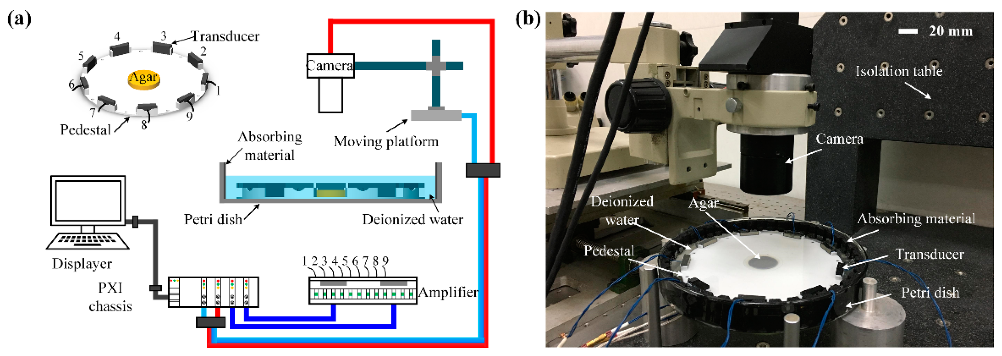
3. Experimental Setup

Figure 5 shows the schematic diagram of our experimental setup. Nine lead zirconate titanate (PZT) transducers (Baoding Yitian Ultrasonic Technology Corporation, Baoding, China) are homogenously mounted on a circular pedestal to generate the desired sound field within a circular region (radius = 0.5 λ ). The plastic pedestal with radius 88.8 mm is placed at the center of the Petri dish that is filled with deionized water. The center frequency of the PZT transducers is 2 MHz, while the width, height and thickness are 20 mm, 10 mm, and 5 mm, respectively. To minimize the reflected wave, each transducer is designed with an epoxy matching layer on the front surface and a tungsten-loaded absorbing backing layer. Without vertical force to balance the gravity, the particle will sink to bottom where the sound intensity is much lower. To solve this problem, the center bottom of the pedestal is covered by agar with 5 mm thickness. The agar has very similar acoustic properties to water and will not disturb the synthesized sound field [56]. Continuous sinusoidal voltage that is generated by the multichannel function generator (homemade PXI platform using FPGA) is amplified by the power amplifiers and then applied to the transducers. The amplitude and phase of each driving signal can be independently modulated with a computer. A visual recording system composed of a CCD camera (GCO-260202, Daheng Imaging, Hangzhou, China), an image acquisition card and a motion platform is used to record the micro-particle position. The actual apparatus is shown in Figure 5b and the related acoustic parameters are listed in Table 1.

4. Results and Discussions

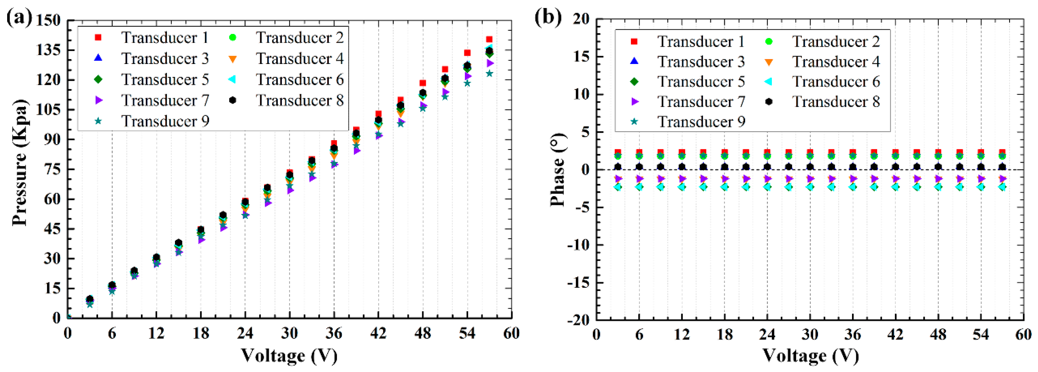
4.1. Transducer Calibration

Synthesizing the sound field requires accordingly modulating the amplitudes and phases of incident waves. Due to the fabrication inconsistency, the generated acoustic pressure of each transducer is calibrated at the pedestal center by using a needle hydrophone (1376, Precision Acoustics, Ltd., Dorchester, UK). To obtain the phase differences, a synchronous signal that is triggered by the transducer driving voltage is used as the reference. Both the pressure and reference signals are sampled simultaneously by a multichannel data acquisition card with 100 MHz sampling rate. Figure 6 shows the measured pressure and the phase of each transducer. In Figure 6a, the pressure variation under the same excitation voltage is clear and the value changes along with the increase of driving voltages. The measurements in Figure 6b are actually the phase difference between the measured pressure and the reference signal. The constant phase difference at various excitation voltages indicates that the performances of employed PZT transducers are stable and time-invariant. For individual transducer, the relation between the excitation voltage and pressure amplitude shows good linearity within the measuring range 0 V–57 V. In the following experiments, the maximum excitation voltage is selected to be 40 V and the calibrated voltages will be applied to the transducer array to obtain the required output pressures.

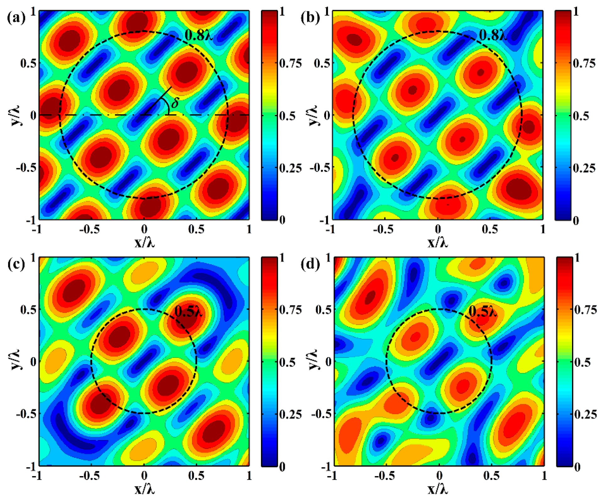
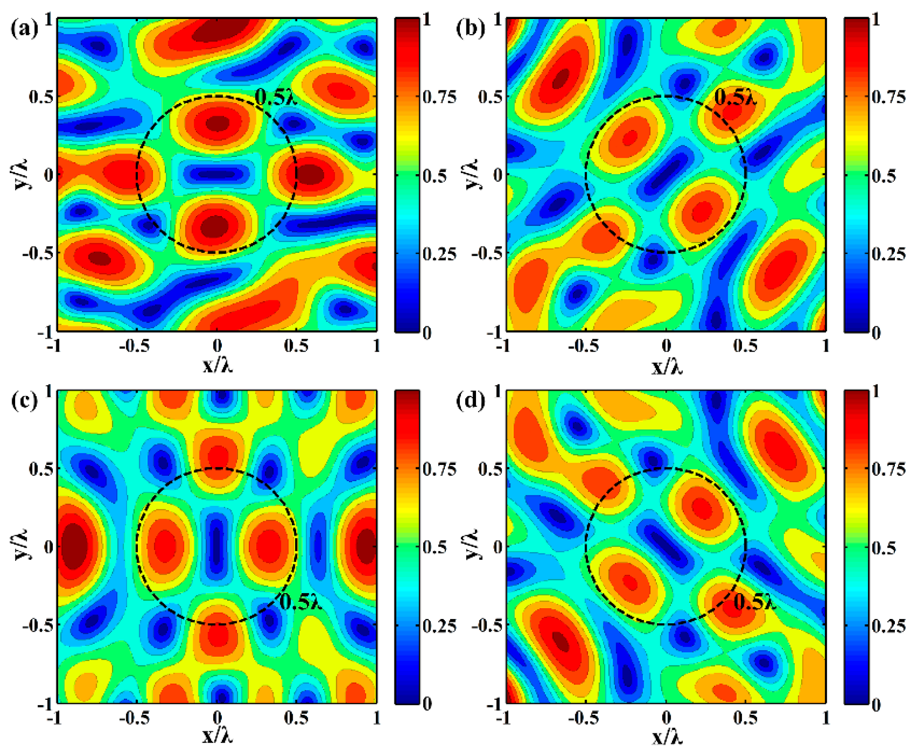
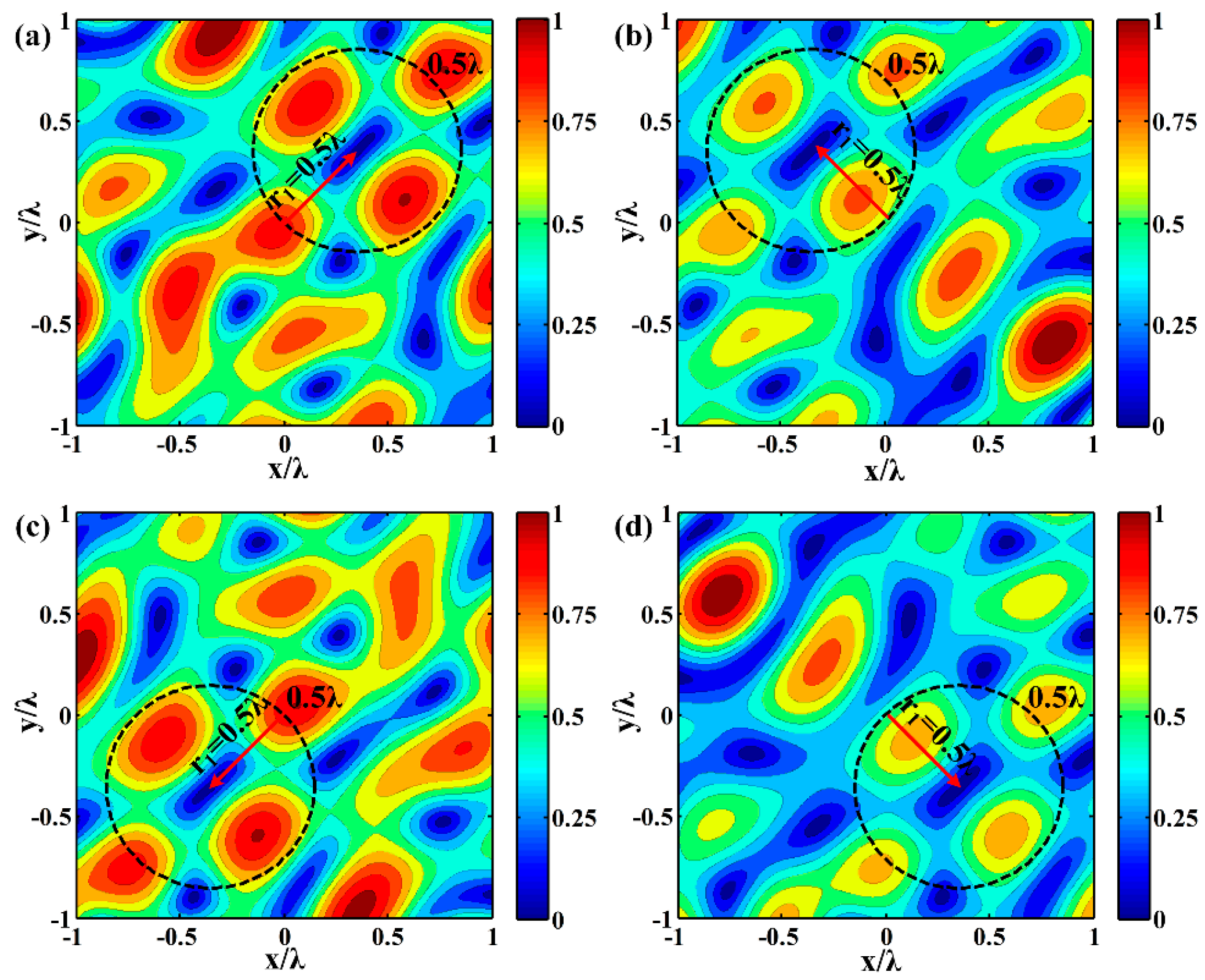
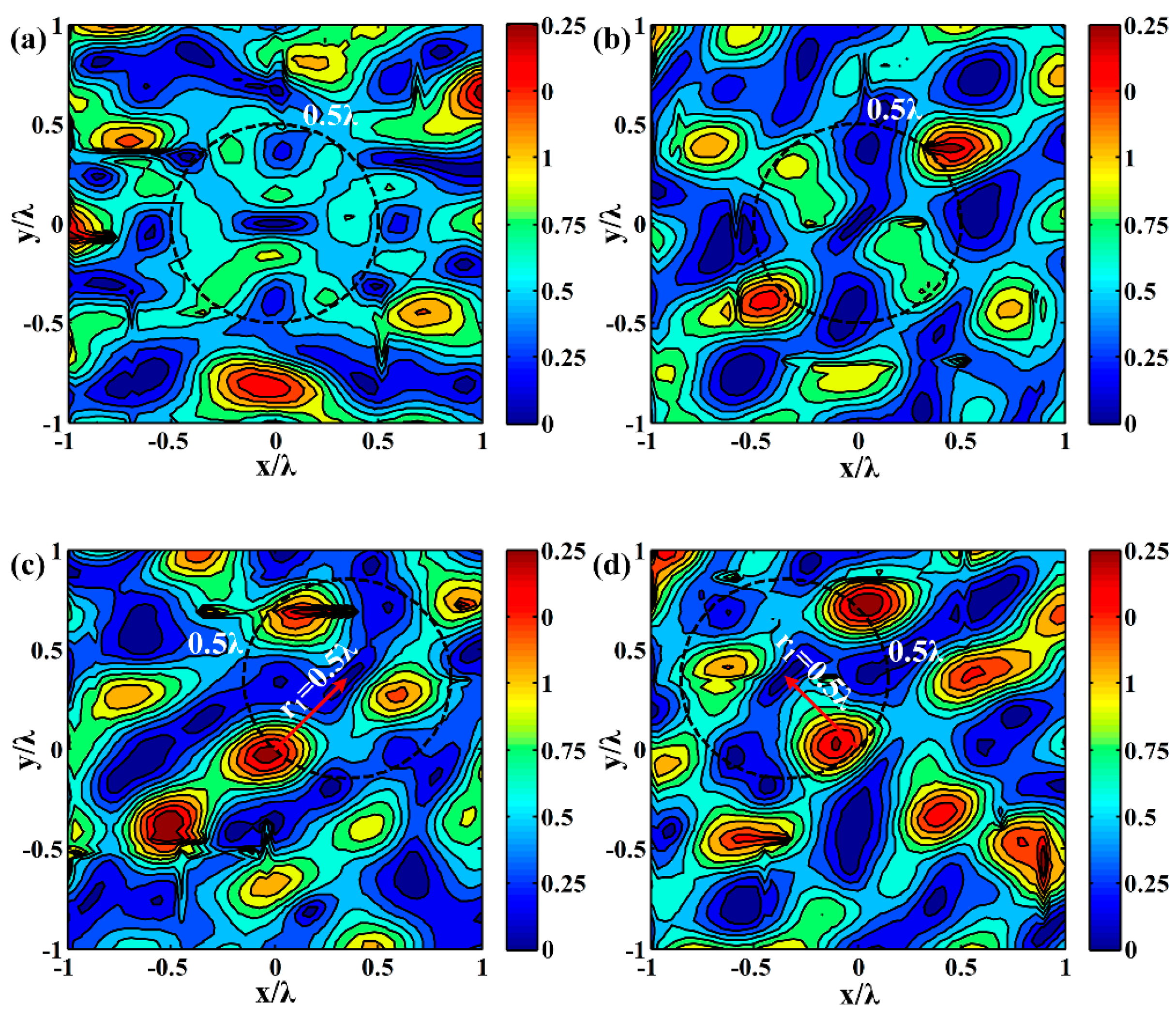
4.2. Measurement of the Synthesized Sound Pressure Field

To verify the effectiveness of employed sound field synthesizing method, the generated pressure distribution is measured by scanning the sound field using the hydrophone. The sampling interval is 50 μm, smaller than λ / 4 (185 μm), which satisfies the requirements for ensuring the accuracy of the acoustic field reconstruction. Figure 7 shows the acoustic pressure distribution within a λ   ×   λ domain located at the center area of the pedestal. The elongated acoustic potential well is formed with the orientation angle 0 and 45 in Figure 7a,b, respectively. Modulating the excitation signals, the pressure node is shifted by 0.5 λ in the direction of 45 and 135 (Figure 7c,d), respectively. In the above process, there are always four anti-nodes round the node as expected. When compared with the predicted pressure field in Figure 3 and Figure 4, the pressure distribution around the node seems to be distorted. This deviation may be caused by: (1) the deviation of incident waves from the ideal plane wave as assumed in the theoretical calculation; (2) the movement errors and electromagnetic noises of step motor when scanning the sound field; (3) the installation error between theoretical and actual positions of PZT transducer; or, (4) inevitable reflected waves. However, the deviation will not obstruct the device functionality, since the long and narrow potential well is effectively formed and transformed, showing good agreement with the theoretical prediction.

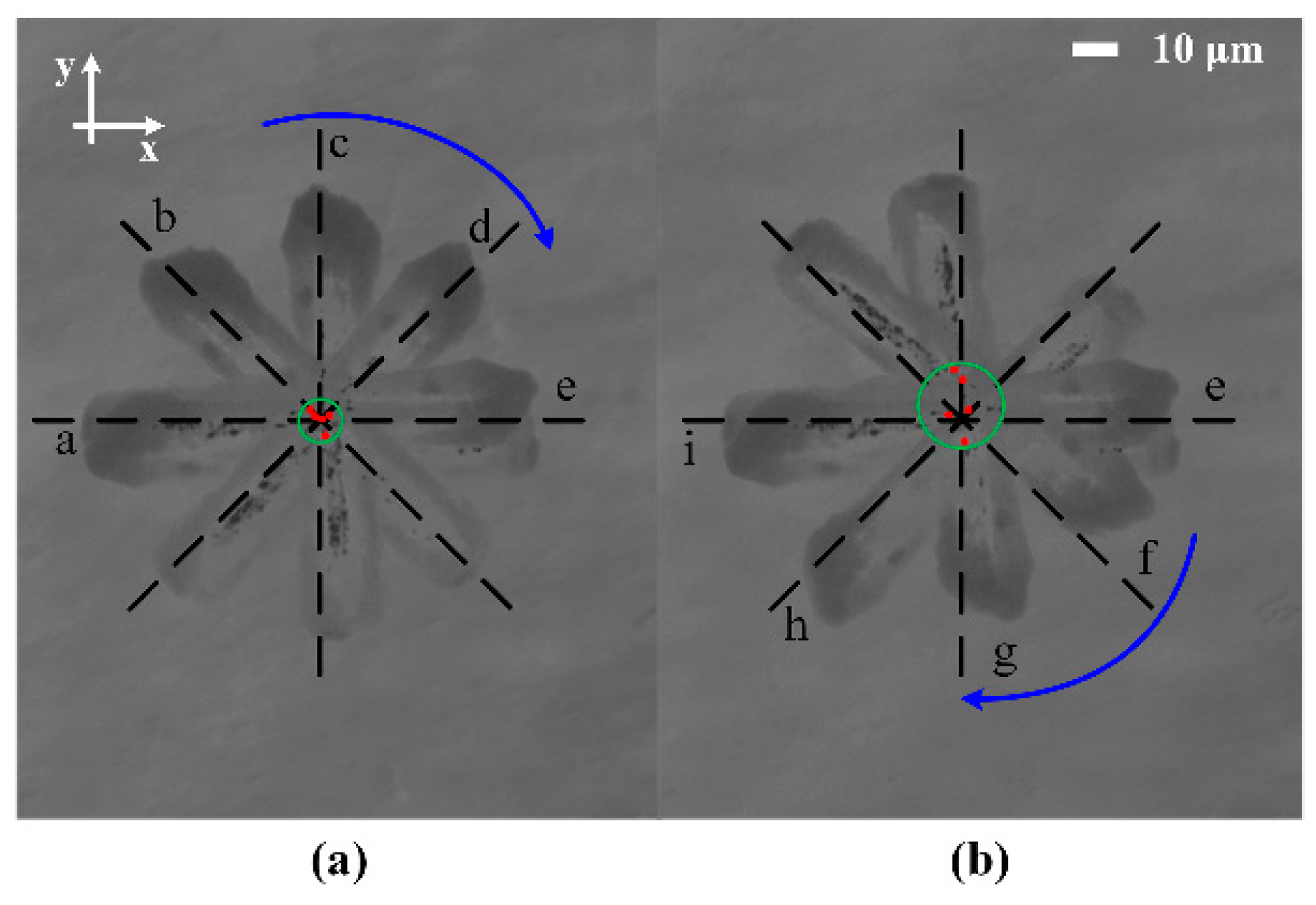
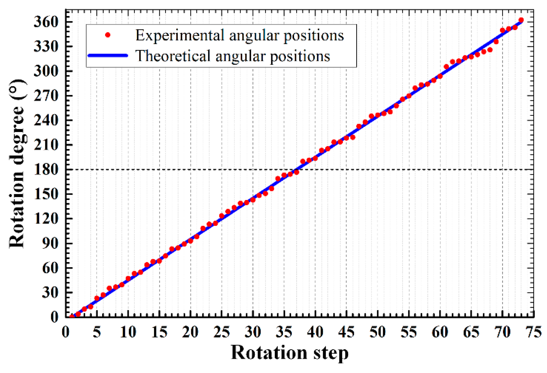
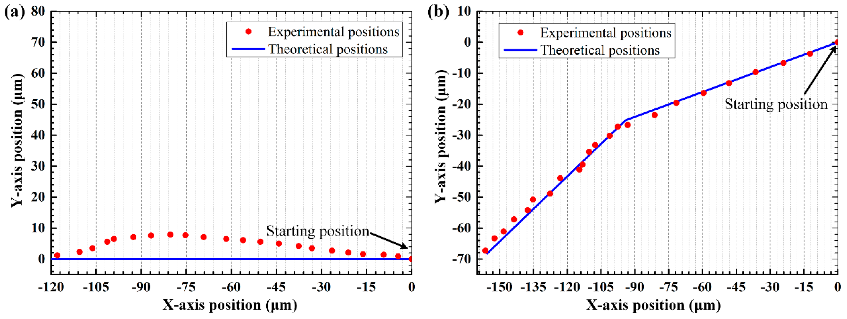
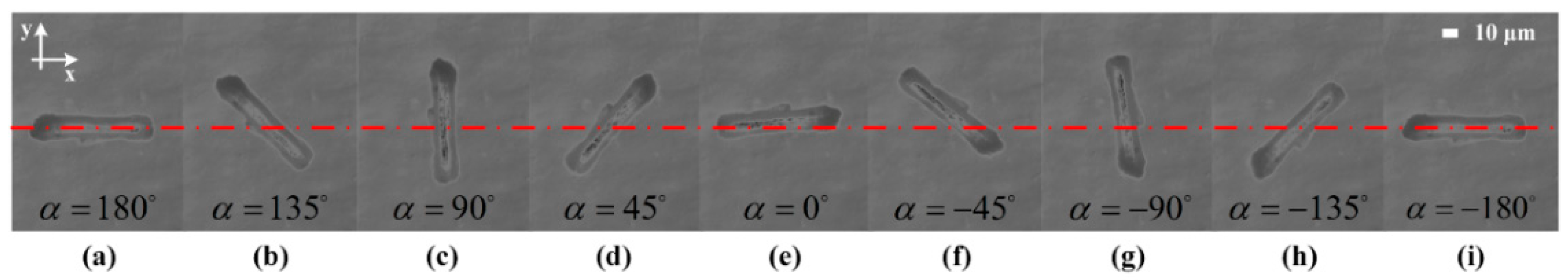
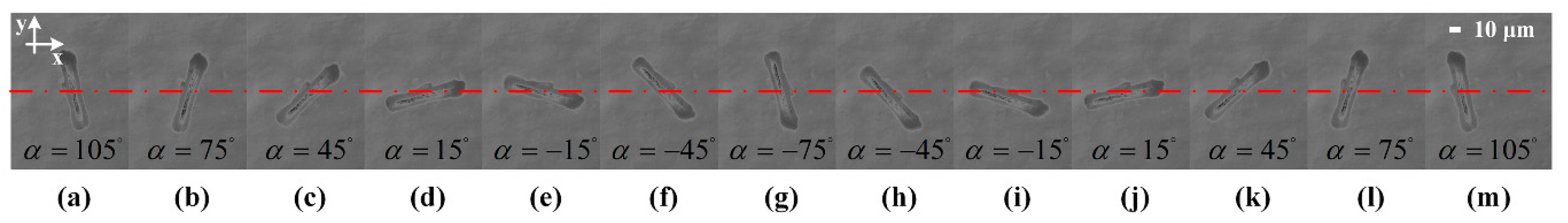
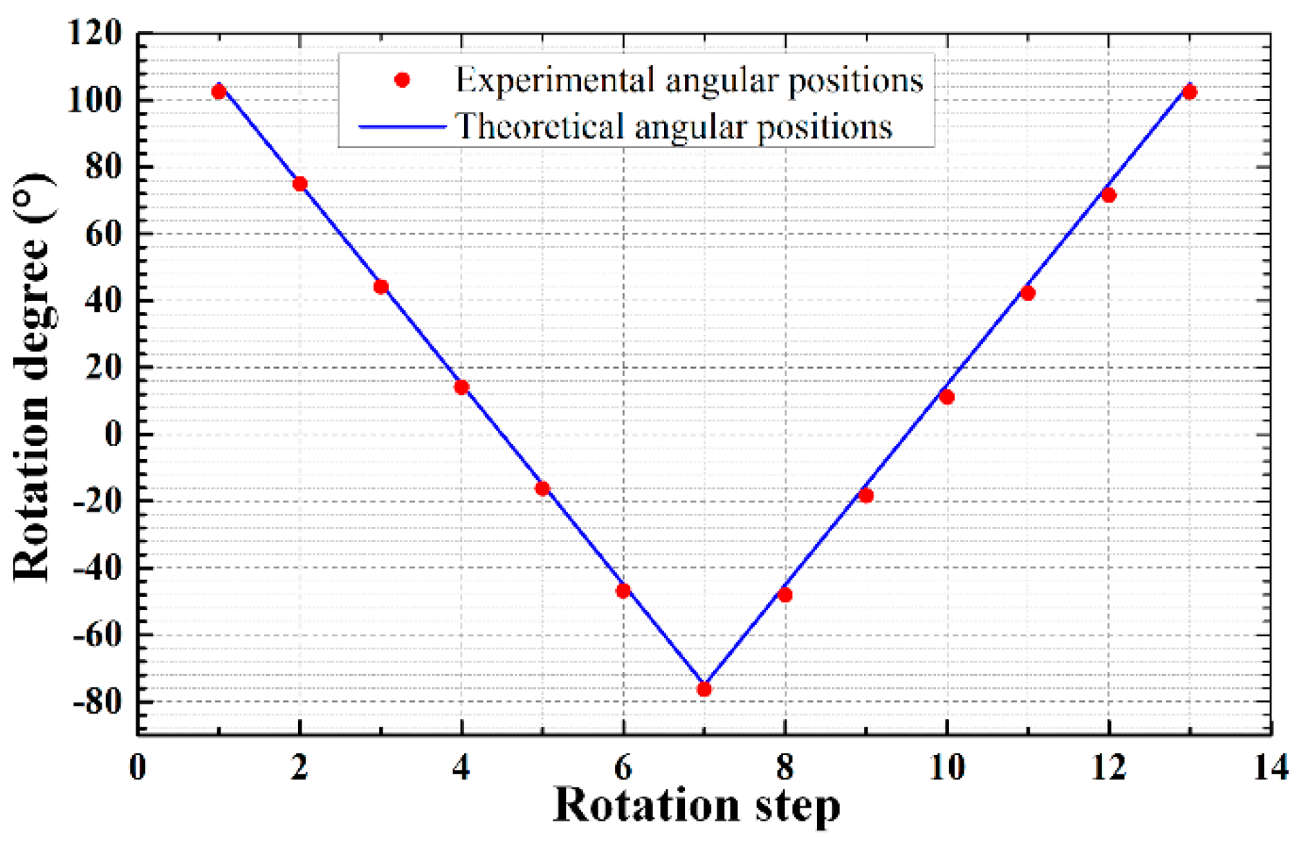
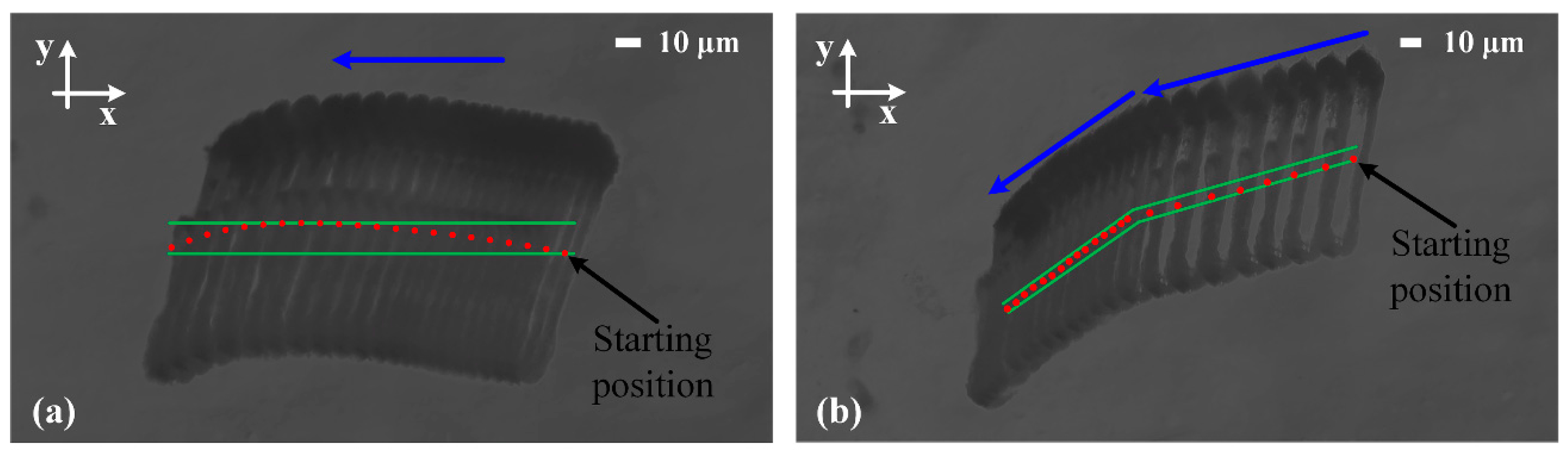
4.3. Particle Rotation and Transportation

A silica rod with 90 μm length and 15 μm diameter is adopted as the manipulation target. The related acoustic parameters of the rod are also listed in Table 1. Figure 8 shows the clockwise rotation of the rod lying on the agar with an interval of 45 . By implementing the excitation variation sequentially, a continuous rotation can be easily obtained. The time interval between each rotation step is 1 s, which is long enough for the rod to reach re-equilibrium. For a better demonstration, the rotation processes from 180 to 0 and 0 to 180 are presented in the superimposed photomicrograph Figure 9a,b, respectively. The red dots indicate the center position of the rod and the black dashed lines represent the theoretical angular position. The silica rod almost rotates around its center step by step and only slightly deviates ( < 5 ) from the theoretical predictions. During the rotation, the rod center deviates from its original position with a maximum value 15 μm, which may be caused by the position fluctuation of the pressure node resulting from the same factors, as mentioned in Section 4.2.
Figure 10 shows the detailed rotation process with a smaller angle interval 5 , in which the measured angular positions are extracted from a series of captured photos. The corresponding theoretical angular position of the synthesized pressure node is also illustrated by the solid line for comparison. Due to the maximal angular deviation about 5 , the resolution of the prototype rotation device is 5 .
The rotation direction can be easily alternated by inverting the adjustment of the transducer excitation. As shown in Figure 11a–g, the rod with an initial angular position of 105 is driven to rotate clockwise with a 30 interval angle. When a half-cycle rotation is performed, the sequence of transducer excitation is inverted. Correspondingly, the rod rotates back to its initial position with the same interval (Figure 11g–m). In addition, the measured angular positions of the particle together with the theoretical value predicted from the field orientation are depicted in Figure 12. The maximal angular deviation is also about 5 .
Transportation of the silica rod to an appointed position along arbitrary trajectory can also be achieved within the same device. This may be of help in the application of medicine tests and micro-assembly, where the drugs or components usually needed to be orientated and then shifted to a specific position. Figure 13 shows the process of two dimensional transportation along different paths. In Figure 13a, the particle is moved by 125 μm along the negative direction of x-axis. During the transporting process, the rod firmly maintains its orientation. Figure 13b shows another trajectory, where the particle is first transported along the direction of 165 , and then changed to the direction of 145 . The first segment distance is about 98 μm and the second one is about 75 μm. The center positions of the silica rod in each moving step along with the theoretical trajectories of the synthesized pressure node are illustrated in Figure 14. In general, there is a good agreement between the actual positions and the predictions. The deviation may be caused by the same factors as mentioned in rotation process. But, for the transporting process, only the phase of each transducer is modulated, which greatly reduces the influence of transducer inconstancy and may improve the manipulation accuracy. Correspondingly, the maximal deviation of the particle center is within 8 μm, smaller than that in rotation process. With appropriate phase modulation, the rod-shaped particle can be transported to any location within the controllable sound field, while keeping its orientation. If the combinations of amplitude and phase modulation are further applied to the transducers, more complicated manipulation, such as performing the rotation and the transportation simultaneously, can be achieved.

5. Conclusions

The ultrasonic rotation and transportation of non-spherical micro-particle by using sound field synthesis technique have been proposed and realized. The employed field synthesis method is based on the technique of mode matching and inverse filtering. A prototype device consisting of nine PZT transducers with megahertz frequency is designed to validate the approach, and the generated pressure field is measured by using a needle hydrophone. Within a circular region of 0.5 λ radius, a localized elongated acoustic potential well is established and then rotated by modulating the excitation signal on each transducer. Correspondingly, a silica rod with 90 μm length and 15 μm diameter can be rotated clockwise or counter-clockwise. The actual angular position of the silica rod agrees with the theoretical predictions, although slight deviation appears in certain rotation steps. The maximum resolution of the current ultrasonic rotation setup is about 5°, which may be further improved by more delicate transducer fabrication and device assembly. In addition, the transportation of particle along different trajectories is also achieved within the same device. The controllability and multi-functionality of the proposed method show great potential in biomedicine and micro-assembly applications. In the future, the more dexterous manipulation, where multi-particles can be independently driven to rotate and shift simultaneously within one microfluidic device, will be studied.

Supplementary Materials

The following are available online at https://www.mdpi.com/2076-3417/8/1/73/s1, Table S1 is corresponding amplitude and phase settings for the field rotation shown in Figure 3. Table S2 is corresponding amplitude and phase settings for the field movement shown in Figure 4.

Acknowledgments

The work is supported by the Natural Science Foundation of China (Grant No. 51675480 and 51205351), Natural Science Foundation of Zhejiang province (Grant No. LZ14E050003) and the Foundation from State Key Laboratory of Fluid Power and Mechatronic Systems (GZKF-201616).

Author Contributions

Shuang Deng and Kun Jia conceived and designed the models and methods presented; Eryong Wu developed the experimental software tools; Eryong Wu, Xuxiao Hu and Keji Yang helped in conception and experiments; Zongwei Fan helped in the simulations; Shuang Deng performed the experiments and analyzed the data; Shuang Deng and Kun Jia wrote this paper.

Conflicts of Interest

The authors declare no conflict of interest.

References

  1. Habaza, M.; Kirschbaum, M.; Guernth-Marschner, C.; Dardikman, G.; Barnea, I.; Korenstein, R.; Duschl, C.; Shaked, N.T. Rapid 3D Refractive-Index Imaging of Live Cells in Suspension without Labeling Using Dielectrophoretic Cell Rotation. Adv. Sci. 2017, 4, 1600205. [Google Scholar] [CrossRef] [PubMed]
  2. Ahmed, D.; Ozcelik, A.; Bojanala, N.; Nama, N.; Upadhyay, A.; Chen, Y.; Hanna-Rose, W.; Huang, T.J. Rotational manipulation of single cells and organisms using acoustic waves. Nat. Commun. 2016, 7, 11085. [Google Scholar] [CrossRef] [PubMed]
  3. Ozcelik, A.; Nama, N.; Huang, P.H.; Kaynak, M.; McReynolds, M.R.; Hanna-Rose, W.; Huang, T.J. Acoustofluidic Rotational Manipulation of Cells and Organisms Using Oscillating Solid Structures. Small 2016, 12, 5120–5125. [Google Scholar] [CrossRef] [PubMed]
  4. Elbez, R.; McNaughton, B.H.; Patel, L.; Pienta, K.J.; Kopelman, R. Nanoparticle induced cell magneto-rotation: Monitoring morphology, stress and drug sensitivity of a suspended single cancer cell. PLoS ONE 2011, 12, e28475. [Google Scholar] [CrossRef] [PubMed]
  5. Tanner, K.; Mori, H.; Mroue, R.; Bruni-Cardoso, A.; Bissell, M.J.; Tanner, K.; Mori, H.; Mroue, R.; Bruni-Cardoso, A.; Bissell, M.J. Coherent angular motion in the establishment of multicellular architecture of glandular tissues. Proc. Natl. Acad. Sci. USA 2012, 109, 1973–1978. [Google Scholar] [CrossRef] [PubMed]
  6. Mohanty, S.K.; Uppal, A.; Gupta, P.K. Self-rotation of red blood cells in optical tweezers: Prospects for high throughput malaria diagnosis. Biotechnol. Lett. 2004, 26, 971–974. [Google Scholar] [CrossRef] [PubMed]
  7. Yamahira, S.; Hatanaka, S.-I.; Kuwabara, M.; Asai, S. Orientation of Fibers in Liquid by Ultrasonic Standing Waves. Jpn. J. Appl. Phys. 2000, 39, 3683–3687. [Google Scholar] [CrossRef]
  8. Lee, P.; Lin, R.; Moon, J.; Lee, L.P. Microfluidic alignment of collagen fibers for in vitro cell culture. Biomed. Microdevices 2006, 8, 35–41. [Google Scholar] [CrossRef] [PubMed]
  9. Vandaele, V.; Lambert, P.; Delchambre, A. Non-contact handling in microassembly: Acoustical levitation. Precis. Eng. 2005, 29, 491–505. [Google Scholar] [CrossRef]
  10. Bogue, R. Assembly of 3D micro-components: A review of recent research. Assem. Autom. 2011, 31, 309–314. [Google Scholar] [CrossRef]
  11. Grier, D.G. A revolution in optical manipulation. Nature 2003, 424, 810–816. [Google Scholar] [CrossRef] [PubMed]
  12. Voldman, J. Electrical Forces for Microscale Cell Manipulation. Annu. Rev. Biomed. Eng. 2006, 8, 425–454. [Google Scholar] [CrossRef] [PubMed]
  13. Keshoju, K.; Xing, H.; Sun, L. Magnetic field driven nanowire rotation in suspension. Appl. Phys. Lett. 2007, 91, 123114. [Google Scholar] [CrossRef]
  14. King, L.V. On the Acoustic Radiation Pressure on Spheres. Proc. R. Soc. Lond. A 1934, 147, 212–240. [Google Scholar] [CrossRef]
  15. Rasmussen, M.B.; Oddershede, L.B.; Siegumfeldt, H. Optical tweezers cause physiological damage to Escherichia coli and Listeria bacteria. Appl. Environ. Microbiol. 2008, 74, 2441–2446. [Google Scholar] [CrossRef] [PubMed]
  16. Guo, F.; Mao, Z.; Chen, Y.; Xie, Z.; Li, P.; Ren, L.; Liu, J.; Yang, J.; Dao, M.; Suresh, S.; et al. Three-dimensional manipulation of single cells using surface acoustic waves. Proc. Natl. Acad. Sci. USA 2016, 113, 1522–1527. [Google Scholar] [CrossRef] [PubMed]
  17. Jia, K.; Yang, K.; Fan, Z.; Ju, B.F. A contactless methodology of picking up micro-particles from rigid surfaces by acoustic radiation force. Rev. Sci. Instrum. 2012, 83, 014902. [Google Scholar] [CrossRef] [PubMed]
  18. Marzo, A.; Seah, S.A.; Drinkwater, B.W.; Sahoo, D.R.; Long, B.; Subramanian, S. Holographic acoustic elements for manipulation of levitated objects. Nat. Commun. 2015, 6, 8661. [Google Scholar] [CrossRef] [PubMed]
  19. Jia, K.; Yang, K.; Mei, D. Quantitative trap and long range transportation of micro-particles by using phase controllable acoustic wave. J. Appl. Phys. 2012, 112, 054908. [Google Scholar] [CrossRef]
  20. Li, P.; Mao, Z.; Peng, Z.; Zhou, L.; Chen, Y.; Huang, P.-H.; Truica, C.I.; Drabick, J.J.; El-Deiry, W.S.; Dao, M.; et al. Acoustic separation of circulating tumor cells. Acoustic separation of circulating tumor cells. Proc. Natl. Acad. Sci. USA 2015, 112, 4970–4975. [Google Scholar] [CrossRef] [PubMed]
  21. Guo, F.; Li, P.; French, J.B.; Mao, Z.; Zhao, H.; Li, S.; Nama, N.; Fick, J.R.; Benkovic, S.J.; Huang, T.J. Controlling cell-cell interactions using surface acoustic waves. Proc. Natl. Acad. Sci. USA 2015, 112, 43–48. [Google Scholar] [CrossRef] [PubMed]
  22. Collino, R.R.; Ray, T.R.; Fleming, R.C.; Sasaki, C.H.; Haj-Hariri, H.B.; Matthew, R. Acoustic field controlled patterning and assembly of anisotropic particles. Extrem. Mech. Lett. 2015, 5, 37–46. [Google Scholar] [CrossRef]
  23. Riaud, A.; Baudoin, M.; Bou Matar, O.; Becerra, L.; Thomas, J.-L. Selective Manipulation of Microscopic Particles with Precursor Swirling Rayleigh Wavesb. Phys. Rev. Appl. 2017, 7, 024007. [Google Scholar] [CrossRef]
  24. Courtney, C.R.P.; Demore, C.E.M.; Wu, H.; Grinenko, A.; Wilcox, P.D.; Cochran, S.; Drinkwater, B.W. Independent trapping and manipulation of microparticles using dexterous acoustic tweezers. Appl. Phys. Lett. 2014, 104, 154103. [Google Scholar] [CrossRef] [Green Version]
  25. Yoon, C.; Kang, B.J.; Lee, C.; Kim, H.H.; Shung, K.K. Multi-particle trapping and manipulation by a high-frequency array transducer. Appl. Phys. Lett. 2014, 105, 214103. [Google Scholar] [CrossRef] [PubMed]
  26. Courtney, C.R.P.; Drinkwater, B.W.; Demore, C.E.M.; Cochran, S.; Grinenko, A.; Wilcox, P.D. Dexterous manipulation of microparticles using Bessel-function acoustic pressure fields. Appl. Phys. Lett. 2013, 102, 123508. [Google Scholar] [CrossRef] [Green Version]
  27. Volke-Sepúlveda, K.; Santillán, A.O.; Boullosa, R.R. Transfer of Angular Momentum to Matter from Acoustical Vortices in Free Space. Phys. Rev. Lett. 2008, 100, 024302. [Google Scholar] [CrossRef] [PubMed]
  28. Skeldon, K.D.; Wilson, C.; Edgar, M.; Padgett, M.J. An acoustic spanner and its associated rotational Doppler shift. New J. Phys. 2008, 10, 013018. [Google Scholar] [CrossRef]
  29. Zhang, L.; Marston, P.L. Angular momentum flux of nonparaxial acoustic vortex beams and torques on axisymmetric objects. Phys. Rev. E 2011, 84, 065601. [Google Scholar] [CrossRef] [PubMed]
  30. Anhauser, A.; Wunenburger, R.; Brasselet, E. Acoustic rotational manipulation using orbital angular momentum transfer. Phys. Rev. Lett. 2012, 109, 034301. [Google Scholar] [CrossRef] [PubMed]
  31. Gspan, S.; Meyer, A.; Bernet, S.; Ritsch-Marte, M. Optoacoustic generation of a helicoidal ultrasonic beam. J. Acoust. Soc. Am. 2004, 115, 1142–1146. [Google Scholar] [CrossRef]
  32. Hefner, B.T.; Marston, P.L. An acoustical helicoidal wave transducer with applications for the alignment of ultrasonic and underwater systems. J. Acoust. Soc. Am. 1999, 106, 3313–3316. [Google Scholar] [CrossRef]
  33. Nyborg, W.L. Acoustic Streaming near a Boundary. J. Acoust. Soc. Am. 1958, 30, 329–339. [Google Scholar] [CrossRef]
  34. Lamprecht, A.; Schwarz, T.; Wang, J.; Dual, J. Viscous torque on spherical micro particles in two orthogonal acoustic standing wave fields. J. Acoust. Soc. Am. 2015, 138, 23–32. [Google Scholar] [CrossRef] [PubMed]
  35. Lamprecht, A.; Schwarz, T.; Wang, J.; Dual, J. Investigations on the time-averaged viscous torque acting on rotating microparticles. In Proceedings of the 2013 International Congress on Ultrasonics, Singapore, 2–5 May 2013; pp. 147–152. [Google Scholar]
  36. Maidanik, G. Torques Due to Acoustical Radiation Pressure. J. Acoust. Soc. Am. 1958, 30, 620–623. [Google Scholar] [CrossRef]
  37. Zhang, L.; Marston, P.L. Acoustic radiation torque and the conservation of angular momentum (L). J. Acoust. Soc. Am. 2011, 4, 1679–1680. [Google Scholar] [CrossRef] [PubMed]
  38. Schwarz, T.; Hahn, P.; Petit-Pierre, G.; Dual, J. Rotation of fibers and other non-spherical particles by the acoustic radiation torque. Microfluid. Nanofluid. 2014, 18, 65–79. [Google Scholar] [CrossRef]
  39. Foresti, D.; Poulikakos, D. Acoustophoretic Contactless Elevation, Orbital Transport and Spinning of Matter in Air. Phys. Rev. Lett. 2014, 112, 024301. [Google Scholar] [CrossRef] [PubMed]
  40. Brodeur, P. Motion of fluid-suspended fibres in a standing wave field. Ultrasonics 1991, 29, 302–307. [Google Scholar] [CrossRef]
  41. Oberti, S.; Neild, A.; Dual, J. Manipulation of micrometer sized particles within a micromachined fluidic device to form two-dimensional patterns using ultrasound. J. Acoust. Soc. Am. 2007, 121, 778–785. [Google Scholar] [CrossRef] [PubMed]
  42. Neild, A.; Oberti, S.; Haake, A.; Dual, J. Finite element modeling of a microparticle manipulator. Ultrasonics 2006, 44, e455–e460. [Google Scholar] [CrossRef] [PubMed]
  43. Neild, A.; Oberti, S.; Dual, J. Design, modeling and characterization of microfluidic devices for ultrasonic manipulation. Sens. Actuators B Chem. 2007, 121, 452–461. [Google Scholar] [CrossRef]
  44. Schwarz, T.; Petit-Pierre, G.; Dual, J. Rotation of non-spherical micro-particles by amplitude modulation of superimposed orthogonal ultrasonic modes. J. Acoust. Soc. Am. 2013, 133, 1260–1268. [Google Scholar] [CrossRef] [PubMed]
  45. Grinenko, A.; Wilcox, P.D.; Courtney, C.R.; Drinkwater, B.W. Proof of principle study of ultrasonic particle manipulation by a circular array device. Proc. Math Phys. Eng. Sci. 2012, 468, 3571–3586. [Google Scholar] [CrossRef] [PubMed]
  46. Ward, D.B.; Abhayapala, T.D. Reproduction of a plane-wave sound field using an array of loudspeakers. IEEE Trans. Speech Audio. Process. 2001, 9, 697–707. [Google Scholar] [CrossRef]
  47. Wu, Y.J.; Abhayapala, T.D. Theory and Design of Soundfield Reproduction Using Continuous Loudspeaker Concept. IEEE Trans Audio Speech Lang. Process. 2009, 17, 107–116. [Google Scholar] [CrossRef]
  48. Fan, Z.; Mei, D.; Yang, K.; Chen, Z. Acoustic radiation torque on an irregularly shaped scatterer in an arbitrary sound field. J. Acoust. Soc. Am. 2008, 124, 2727–2732. [Google Scholar] [CrossRef] [PubMed]
  49. Jia, K.; Fan, Z.; Yang, K. 3 DOF noncontact clamping stage for micro-stereolithography on embedded material. Int. J. Appl. Electrom. 2016, 52, 183–190. [Google Scholar] [CrossRef]
  50. Doinikov, A.A. Acoustic radiation pressure on a rigid sphere in a viscous fluid. Proc. R. Soc. Loud. A 1994, 447, 447–466. [Google Scholar] [CrossRef]
  51. Danilov, S.D.; Mironov, M.A. Mean force on a small sphere in a sound field in a viscous fluid. J. Acoust. Soc. Am. 2000, 107, 143–153. [Google Scholar] [CrossRef] [PubMed]
  52. Settnes, M.; Bruus, H. Forces acting on a small particle in an acoustical field in a viscous fluid. Phys. Rev. E 2012, 85, 016327. [Google Scholar] [CrossRef] [PubMed]
  53. Jia, K.; Meng, J.; Yang, K.; Fan, Z.; Ju, B.-F. Building the isotropic acoustic potential well with strong constraint boundary to improve the stability of ultrasonic transportation. J. Appl. Phys. 2013, 113, 064903. [Google Scholar] [CrossRef]
  54. Williams, E.G. Fourier Acoustics: Sound Radiation and Nearfield Acoustical Holography; Academic Press: San Diego, CA, USA, 1999; pp. 239–251. ISBN 978-0-12-753960-7. [Google Scholar]
  55. Deng, S.; Jia, K.; Chen, J.; Mei, D.; Yang, K. Relative position control and coalescence of independent microparticles using ultrasonic waves. J. Appl. Phys. 2017, 121, 184503. [Google Scholar] [CrossRef]
  56. Bernassau, A.L.; Glynne-Jones, P.; Gesellchen, F.; Riehle, M.; Hill, M.; Cumming, D.R.S. Controlling acoustic streaming in an ultrasonic heptagonal tweezers with application to cell manipulation. Ultrasonics 2014, 54, 268–274. [Google Scholar] [CrossRef] [PubMed]
Figure 1. (a) The acoustic radiation torque on an asymmetric particle in the acoustic field is dependent on the angular position σ; (b) The geometric parameter definitions for discretized Kirchhoff–Helmholtz integral equation within an arbitrary shaped 2D domain; (c) The principles of sound field synthesis technique. Multi plane wave transducers are homogenously mounted on a circular and the desired acoustic field is synthesized within the range S.
Applsci 08 00073 g001
Figure 2. (a) The desired acoustic pressure field for manipulating non-spherical micro-particle. The black dashed line indicates the boundary of acoustic field to be synthesized. Desired fields are synthesized within different regions: (b) 0.8 λ with the truncated order M = 6 and thirteen transducers; (c) 0.5 λ with the truncated order M = 4 and thirteen transducers; and, (d) 0.5 λ with the truncated order M = 4 and nine transducers.
Applsci 08 00073 g002
Figure 3. Anticlockwise rotation of the synthesized pressure field from 0 to 135 with 45 interval: (a) 0 ; (b) 45 ; (c) 90 ; (d) 135 .
Applsci 08 00073 g003
Figure 4. Spatial transformation of the synthesized sound field with an appointed distance 0.5 λ along different directions. (a) 45 , (b) 135 , (c) 225 , and (d) 315 .
Applsci 08 00073 g004
Figure 5. (a) Schematic diagram of the experimental setup; (b) Actual setup.
Applsci 08 00073 g005
Figure 6. The measured pressure and the phase difference of each transducer at various excitation voltage. (a) The measured pressure. (b) The measured phase difference.
Applsci 08 00073 g006
Figure 7. The measured pressure distribution within a λ × λ domain located at the center area of the pedestal. The elongated acoustic potential well is formed with orientation angle 0 in (a) and 45 in (b) and then shifted by 0.5 λ in the direction of 45 in (c) and 135 in (d).
Applsci 08 00073 g007
Figure 8. The clockwise rotation of the silica rod lying on the agar from 180 to 180 (ai) with 45 interval.
Applsci 08 00073 g008
Figure 9. Rotation from 180° to 0° (a) and 0° to −180° (b).
Applsci 08 00073 g009
Figure 10. Rotation with 5° angle interval.
Applsci 08 00073 g010
Figure 11. Alternating rotation by inverting the adjustment of the transducer excitation. (ag) show a half-cycle clockwise rotation with a 30 interval angle and (gm) is the reverse rotation with the same interval.
Applsci 08 00073 g011
Figure 12. Measured and theoretical angular in the process of alternating the particle rotation direction.
Applsci 08 00073 g012
Figure 13. Transportation of the silica rod along different trajectories. (a) The particle is moved by 125 μm along the negative direction of x-axis; (b) The particle is first transported along the direction of 165 by 98 μm, and then changed to the direction of 145 by 75 μm. The red dots are the center positions of the particle and the green lines indicate the fluctuation range of the particle center.
Applsci 08 00073 g013
Figure 14. The theoretical and experimental center positions of the silica rod in each moving step (a) Along the trajectory indicated in Figure 13a; (b) Along the trajectory indicated in Figure 13b.
Applsci 08 00073 g014
Table 1. Acoustic parameters of deionized water and silica bead.
NameDensity (g/cm3)Sound Speed (m/s)
Deionized water1.01480
Strip-shaped silica particle2.335340

