1. Introduction
Many factors influence the definition and selection of the structural design concept. In general, in complex systems, structural designing is an iterative process. The process starts with the conceptual design of possible alternatives, which could be considered to satisfy the general performance requirements and are likely to meet the main mission constraints (e.g., mass, interfaces, operation and cost).
The system’s engineering activities are equally valid and necessary at all levels of decomposition within the space product. In particular, the verification engineering function, which iteratively compares the outputs from other functions with each other, in order to converge upon satisfactory requirements, functional architecture, and physical configuration, defines and implements the processes by which the finalized product design is proved to be compliant with its requirements.
According to the European Space Agency (ESA) standards [
1], the verification process activities shall be incrementally performed at different levels and in different stages, applying a coherent bottom-up building-block concept and utilizing a suitable combination of different verification methods. To reach the verification objectives, a verification approach shall be defined in an early phase of the project by analyzing the requirements to be verified, taking into account the following:
design peculiarities;
the qualification status of the candidate solution;
the availability and maturity of verification tools;
verification and test methodologies;
programmatic constraints;
the cost and schedule.
In the mechanical design of launchers, the verification of vibroacoustics requirements is crucial for guaranteeing the preservation of the payloads’ functionalities during the preorbital phase. This process is particularly affected by the lack of both the availability and maturity of standardized design testing tools. This work describes the innovative integrated process used at the design-stage level in the verification of the Vega-C rocket project development.
The interstages of the new Vettore Europeo di Generazione Avanzata (VEGA, European Advanced Generation Vector) configurations are examined in the framework of the ESA-funded VEGA Consolidation and Evolution Program (VECEP), in order to derive the acceleration level at the equipment locations and the average vibration response of the connecting interfaces. The analysis is needed in the framework of the re-engineering phase aimed at further increasing the performance of the VEGA launcher, and it is part of a preliminary numerical verification necessary to assess the compliance of the designed structure with the acceleration level imposed as a limit for the protection of the equipment and payload.
The complexity of the analysis is driven by two critical elements, which have been addressed in this work with an innovative approach. First, the acoustic pressure generated at lift-off cannot be calculated with the resolution needed because of the computational complexity of the simulation. Then, the vibroacoustic analysis driven by the calculated acoustic field on the basis of finite-element/boundary-element method (FEM/BEM) techniques turns out to be unfeasible in a medium to high frequency range, even when resorting to computationally efficient approaches such as the acoustic transfer vector (ATV) or modal ATV (MATV) [
2], because of the high modal density of the structure. On the other hand, the employment of a fully energy-based approach in this frequency range is restricted by the need to simulate the equipment as lumped masses, connected to the main structure throughout rigid links.
In this paper, we propose an integrated verification approach [
3,
4,
5] exploiting an innovative semiempirical Eldred-based source model with BEM propagation [
6,
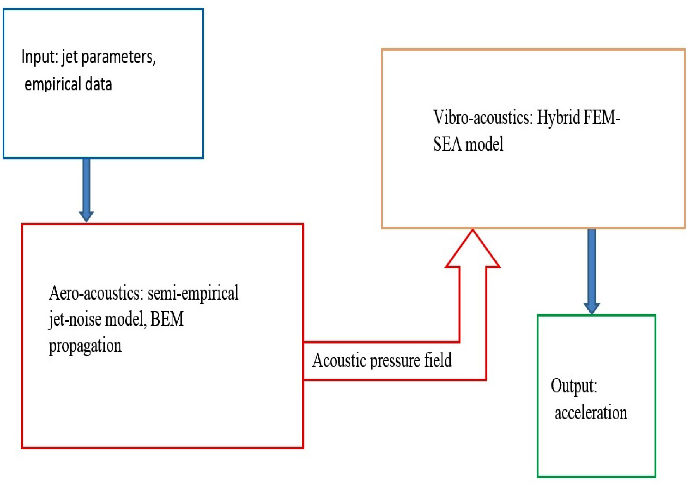
7] for building the jet acoustic pressure field, as well as a state-of-the-art hybrid FEM/statistical energy analysis (SEA) method adopted to combine the equipment’s local deterministic responses with the mean value of the dynamic response of the launcher’s major sections. In
Figure 1, the logical structure of the whole integrated method is shown, with the acoustic field calculation feeding the structural dynamic simulation.
The power of the proposed approach, with respect to other hybrid vibroacoustic methods, lies in its integration with the aeroacoustic component. In fact, a realistic model for the forcing pressure clearly implies a realistic reconstruction of the structural response in the operating condition considered.
The concept of a space launcher can be, in some sense, elusive. It is thus worthy to try to define the range of applicability of the approach described in this work. In particular, the model used for reconstructing the acoustic pressure field acting on the structure and due to jet fluid dynamics aspects is general and independent from the type of the structure taken into account as well as from considering a horizontal or vertical launch. On the other hand, the hybrid techniques describing the response of the structure to the load cannot be reliable for geometries including wings, because of the complications arising in the model and the possible fall down of the diffuse-field assumption.
The semiempirical approach for reconstructing the acoustical pressure component of the rocket jet is described in
Section 2. It is an improvement of the Eldred Standard model, based on heuristic assumptions and scaling laws, properly tuned against experimental data from different rocket engines [
8,
9,
10,
11]. In this simple model, in order to determine a realistic equivalent noise source, several parameters, such as the vehicle geometry or launch pad configurations, have to be taken into account. Several hybrid methods have been proposed for overcoming this limit [
12,
13], and the new formulation contains an explicit expression for the acoustic pressure of each noise source, in terms of amplitude and phase, in order to account for correlation effects and propagate the signal using a wave equation. The noise prediction obtained with the revised Eldred-based model has thus been used for formulating an empirical/BEM approach that allows us to evaluate the scattering effects, which, summed with the direct, correlated acoustical pressure, is exploited for the prediction of the aeroacoustics loads of the VEGA launch vehicle at lift-off.
The hybrid FEM/SEA vibroacoustic approach is described and validated in
Section 3. The implemented analysis resorts to a FEM solver to extract the modal parameters associated to the deterministic subsystems of the VEGA interstages. The development of the statistical subsystems and the set-up of the global hybrid models are realised within a numerical environment, formerly devoted to SEA methodology only, in which the required dynamic analysis is also performed. The structural and acoustical models of the interstages are validated through a comparison with theoretical and numerical estimates. As required for the assessment of the equipment qualification status, the activity is finalized with the delivery of the dynamic response database, numerically generated by applying the acoustic pressure field to the interstage validated models.
Two sections, dealing with the discussion of the results and some concluding remarks, close the paper.
2. Jet-Noise Source Model and Propagation
The complexity of the detailed modeling of the acoustic component in rocket exhaust can be circumvented using empirical approaches, on the basis of the assumption that an equivalent source distribution can be determined using few parameters (e.g., jet exit conditions and acoustic efficiency) and some universal curves determined experimentally. In particular, the first Eldred model [
8] is based on the observation that each slice of the jet contributes to acoustic radiation, mostly in the frequency band
that depends on the distance of the slice from the exhaust. The subsequent reformulation of the approach states that each slice contributes to the full noise spectral frequency content with an overall power that depends on its curvilinear distance from the exhaust [
12]. Differently from the original Eldred model, which directly provides a definition of the sound pressure level (SPL), its reformulation can be revised to provide an explicit formulation of the acoustic pressure phasor
[
14]. In particular, this simpler version of the reformulated semiempirical model moves from the relation
equating the phasor of the incident pressure,
, due to the
jth source, to the corresponding monopole amplitude,
, with
indicating the power,
being the air density and
c being the speed of sound at ambient conditions, through the green function of the nonconvective Helmholtz operator,
the directivity effect produced by the inflow refraction, can be taken into account with a directivity function
, where
and
I indicates the intensity. Hence, the pressure of each monopole source, composing the equivalent set that reproduces the jet noise, can be expressed in the form
with
indicating the angle between the observer and the monopole source position.
The second formulation of the Eldred model assumes a contribution from each jet slice to the full noise spectral frequency content with an overall power that depends on its curvilinear distance from the exhaust [
12]. Denoting
as the sound power per unit axial length, the contribution of each slide reads as
where
is a jet reference length, and
k denotes the
kth slice at a distance
from the exhaust.
represents the overall acoustic power [
15] of the engine, which is a fraction of the mechanical power
(
with
).
The overall power density level,
, can be distributed on the frequency spectrum. Denoting with
the sound power level per unit axial length and unit frequency, one can introduce the reduced sound power density:
with
being the jet speed at the exhaust,
being the ambient sound speed and
being the jet exhaust speed. Consequently, it is possible to obtain the monopole source’s acoustic power at each axial length and for each frequency from
The revised Eldred-based model is enriched with two free parameters, and , respectively related to the mixing-layer turbulence length scale and its integral correlation length.
The Eldred standard model describes the jet noise with a set of equivalent sources, laying along the jet axis with no consideration of their number or spatial distribution. It is reasonable to think that the spatial scale of each source, and consequently its number, is related to its turbulent length scale. In analogy with similar physical consideration taken from the Stochastic Generation and Radiation model for turbulent Noise (SNGR) [
16], the energy peak of the universal energy spectrum can be related to the turbulent length scale through a free mode parameter, according to
This equation puts in relation the turbulent scale
with the value of the curvilinear abscissa
s, and takes into account the experimental evidence according to which the energy peak has its maximum at a value 1.5 of the modified Strouhal number [
14]. Equation (
6) states that the turbulent scale grows up gradually increasing the distance from the jet nozzle, with sources emitting at lower frequencies at a greater distance from it.
On the other hand, a classical result [
17] relates the integral length scale
for homogeneous, isotropic turbulence with the correlation length
of a vortex structure at a single wavenumber
, according to the following equation:
This equation implies then that the correlation length at each frequency is proportional to the wavelength. In the revised Eldred-based model, it would means that each single source is correlated with all the others with a correlation length that depends on the frequency considered. In order to enhance the capabilities of the revised model and in order to tune the model exploiting the experimental data, the parameter
is then added to the equation:
A comprehensive analysis concerning the role of
is provided in [
14].
Both Eldred-based uncorrelated and correlated source models can be used for the hybrid empirical/BEM computation. The hybrid approach’s implementation has firstly been tested to check that the total pressure, p, is equal to the Eldred incident field, , when a vanishing scattering BEM surface is considered ().
3. Hybrid FEM/SEA Model and Interstage Response Analysis
As pointed out in the introduction, the objective of this work is to predict the acceleration response level at the equipment and payload location, for subsequent verification of their qualification status. In addition, the dynamic average response of the VEGA interstage interfaces IS01, IS12 and IS23 to the acoustic field generated at lift-off by the P120 engine has been calculated with the innovative approach described in the previous section.
A numerical prediction has been obtained through the development of hybrid FEM/SEA models and their analysis in the 100–1600 Hz frequency range using the commercial code VAOne [
18], in order to overcome the limitation of deterministic tools in the investigated frequency range. The fourth section of VEGA, constituted by the interstage IS34, the Attitude Vernier Upper Module (AVUM) and the Fairing, was left out from the numerical investigation because it has been unchanged with respect to the old configuration. The large frequency range spread of the pressure power spectra motivates the need for a vibroacoustic response analysis accounting for all the frequency content of the main external pressure field to avoid underestimating the equipment’s and components’ acceleration levels. Despite the relatively high skin thickness and the opportunity to perform the analysis on each component separately, the large dimensions of the VEGA interstages still require the involvement of a large number of structural modes, not to mention at all the even higher modal density of the coupled interior acoustic cavities.
As a consequence, above 400/500 Hz, the FEM technique turns out to be computationally unfeasible even when resorting to modal superposition procedures, and the SEA approach becomes more appropriate for acquiring the responses of both the structure and the acoustic cavity. As a matter of fact, SEA represents systems in terms of a number of coupled subsystems, taking into account the global energy trade-off due to their interaction, namely, energy storage, transmission and dissipation. The parameters in SEA equations are typically obtained with certain statistical assumptions about the dynamic properties of each subsystem. For running the calculations, the commercial code VAOne has been used.
The code allows for a complete range of analysis because different solution methods and modules are available, specifically, FEM, BEM and SEA. The capabilities in dealing with any kind of dynamic problem are even enlarged by the option to develop hybrid models, in which all available methodologies are combined. The development of structural models entirely based on a SEA approach was restricted by the need to simulate the equipment as a lumped mass, connected to the main structure throughout rigid links. These components are not suitable for SEA modeling because they have no modal behavior by definition, while a large modal participation is required for a SEA model to be accurate.
The adoption of a hybrid approach was mandatory for the monitoring of the equipment acceleration levels, in order to verify their qualification status. Consequently, for all interstages, a full SEA model could not be developed, and a careful identification of the number and extension of the interstage parts to be modeled as FEM subsystems was required to avoid building up a model unsuitable for a SEA approach. Moreover, all the external and internal interfaces have been modeled as FEM subsystems to retain all their dynamic contributions, otherwise ignored by using a SEA “beam”-type subsystem for their simulation.
The correct balance among the different type of subsystems (either SEA or FEM) was essential to allow a fairly quick analysis with no penalties in terms of accuracy. General rules to check the accuracy of a SEA subsystem are based on the following concepts, applicable to the frequency bands chosen for the analysis:
Both parameters depend on the modal density, representing the number of modes per hertz associated to the subsystem, while the MOF is also dependent on the loss factor; together they provide the conditions for which a “diffuse-kind” vibration or acoustic field characterizes the SEA subsystem’s dynamic behavior.
Hybrid FEM/SEA modeling, then, requires an iterative process aiming for the exact identification of the frequency range accuracy for each subsystem in order to correctly define their geometries and dimensions. For accurate predictions in a large frequency band, more than one model might be necessary, where the number of subsystems modeled according to one methodology or the other could consequently change. The validation process of the SEA and hybrid structural models is carried out by relying on the following:
Theoretical assessments of SEA subsystems against simplified formulations to verify the consistency with some global distinguishing parameters.
Numerical checks on sections of the interstages performed by comparison of the prediction data provided by the hybrid model and by the equivalent FEM model.
Numerical mutual checks between the full interstage hybrid and FEM models performed in the overlap frequency region where the two approaches are reasonably applicable.
The acoustic loading applied is considered a diffuse field, acting on the external surface of interstages; the power spectral density (PSD) of the pressure autocorrelation function is assumed to be constant over the entire surface.
The responses of all the interstages are expected to be characterized by a more or less uniform modal energy, which is beneficial to reduce the effect of nonideal modeling, in terms of SEA accuracy, of some of the model components, and in order to reduce the effect of not simulating the entire launch vehicle.
In fact, modal energy equivalence can also be interpreted as an opportunity to perform a first approximation analysis on each component or subsystem by assuming it as being disjointed from the others. This assumption is strictly applicable to models made of SEA subsystems only and for which SEA criteria are fulfilled; thus, the application to hybrid models must be carefully verified, because of the “non-diffuse-field” characteristics of FEM subsystems.
The Interstage Models
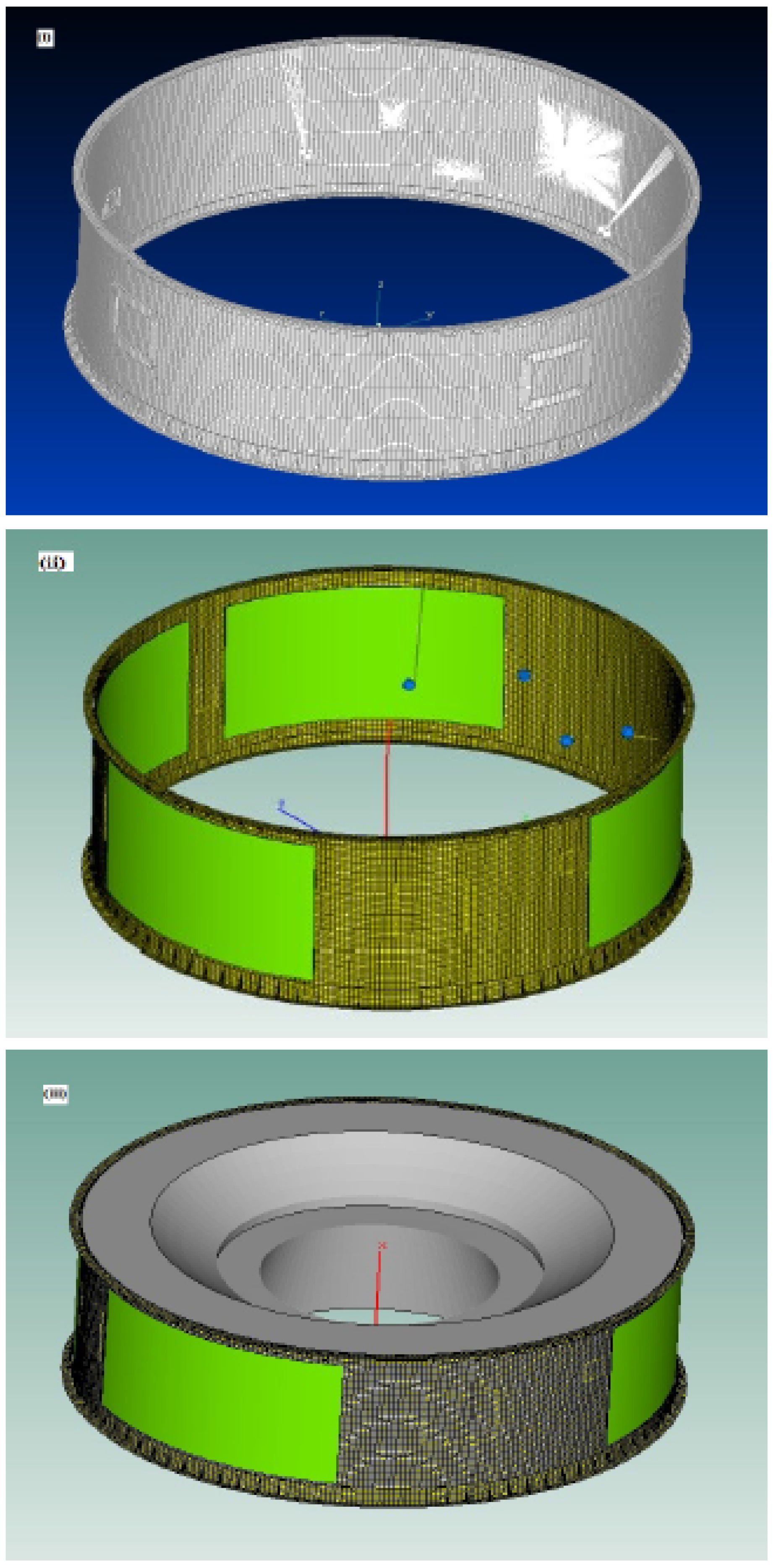
The interstages IS01 (
Figure 2) and IS12 are made of aluminium. The former is cylindrical and presents a nonuniform lateral surface thickness, 4 mm thicker in the area in which the openings are located, whereas the latter is constituted by two sections, having the form of a cone frustum connected through an internal interface. The third interstage, IS23, has different characteristics; it is realized by a composite material, and it is reinforced over the lateral surface by axial and circumferential stiffeners. The shape is still conical, split into two sections connected by an internal frame. Frames, reinforcing elements and skins are all constituted of a composite material.
The simpler VEGA section among those analyzed, namely, interstage IS01, is taken as an example for illustrating the final part of the design verification described in this paper. Its main geometrical and dynamic characteristics are summarized in
Table 1, along with the theoretical estimates of the ring and coincidence frequencies referred to the mean thickness.
The various subsystems of the interstage model are shown in
Figure 2: the SEA structural subsystem in green, the FEM structural subsystem in gold–brown, and the SEA acoustic subsystem in grey. In the same figure, the original FEM model used for deriving the hybrid model has been reported.
In particular, the hybrid FEM/SEA model has been built up by assembling six FEM structural subsystems (two large subsystems for the upper and lower rings, two large subsystems for the areas in which several equipment are located, and two small subsystems, each connected to a single equipment component), four large SEA structural subsystems (modeling the areas with lower thickness) and one SEA acoustic subsystem.
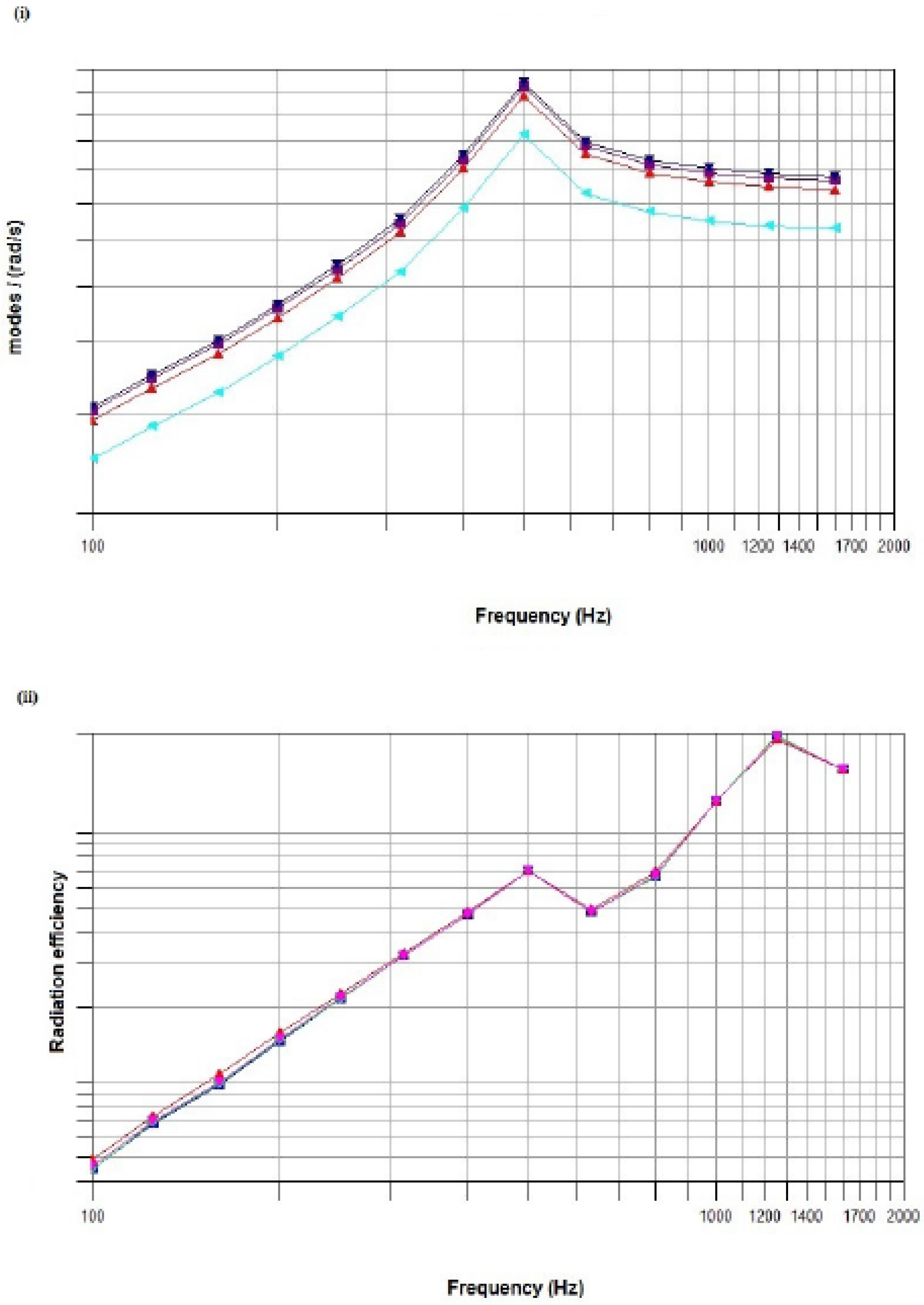
A preliminary check of the model was performed by analyzing the modal density and radiation efficiency of the interstage: all SEA subsystems in the IS01 hybrid model presented a good agreement with the characteristic theoretical parameters reported in
Table 1 and their asymptotic values, as shown in
Figure 3, where the modal density and radiation efficiency are reported for each SEA subsystem of the hybrid model.
For each SEA subsystem, the modal density displays how the ring frequency is close to the theoretical value. Asymptotic values also confirm theoretical modal density estimates, evaluated for the curved subsystems through the equivalent flat panel relation, valid above the ring frequency
. This frequency, along with the structural modal density
, can be expressed as
in which the structural properties (elasticity modulus
E, Poisson ratio
, volume density
, and thickness
h) are recalled along with the inner ring radius
r, the axial length
L and the arc angle
[
19]. The radiation efficiency curves confirm the theoretical values for both the characteristic frequencies (ring and coincidence), as they superimpose almost perfectly with discrepancies limited to low frequencies. The congruency of the SEA subsystems is thus assured.
An assessment process based on a comparison with an equivalent full deterministic analysis is also applied, either to limited portions of the interstage hybrid models to verify the accuracy of the coupling loss factors among specific SEA and FEM subsystems, or to the entire interstage models for an overall check of the hybrid approach’s accuracy. For each examined system, the results are compared in the frequency range for which the two models (hybrid and full FEM) are expected to be accurate.
4. Discussion
The results of the proposed integrated verification process are discussed in this section. Verification and validation are both crucial in assessing the project robustness. However, the analysis proposed here has been performed at the design level; thus the validation with experimental data is to be performed afterwards.
4.1. Resulting Pressure
In the framework of the VECEP, the Italian Aerospace Research Centre (
Centro Italiano Ricerche Aerospaziali, CIRA) and the prime contractor, Avio SpA, are involved in the prediction of the aeroacoustic loads at lift-off due to the introduction of the first-stage solid rocket motor P120, a longer version of the currently used P80 motor. In this work, the empirical models used within the design verification process have been fed with the experimental data acquired using a 1/20 scaled mock-up of the VEGA launcher equipped with the first-stage solid rocket motor P80 [
12,
20]. Two experimental campaigns have been carried out by Avio, ELV and ONERA in the framework of the VEGA program [
20,
21] and by Avio, ELV and CIRA in the framework of the Italian Space Agency-funded project CAST (
Configurazioni AeroTermodinamiche per Sistemi di Trasporto spaziale, AeroThermodynamic Configuration for space Transport Systems) [
12,
22].The launcher mock-up has been conceived to reproduce the same acoustic environment generated by the full-scale VEGA first-stage solid rocket motor P80 at different launcher altitudes, from 0 to 75 m, corresponding to the first 4 s of the VEGA ascent trajectory during lift-off.
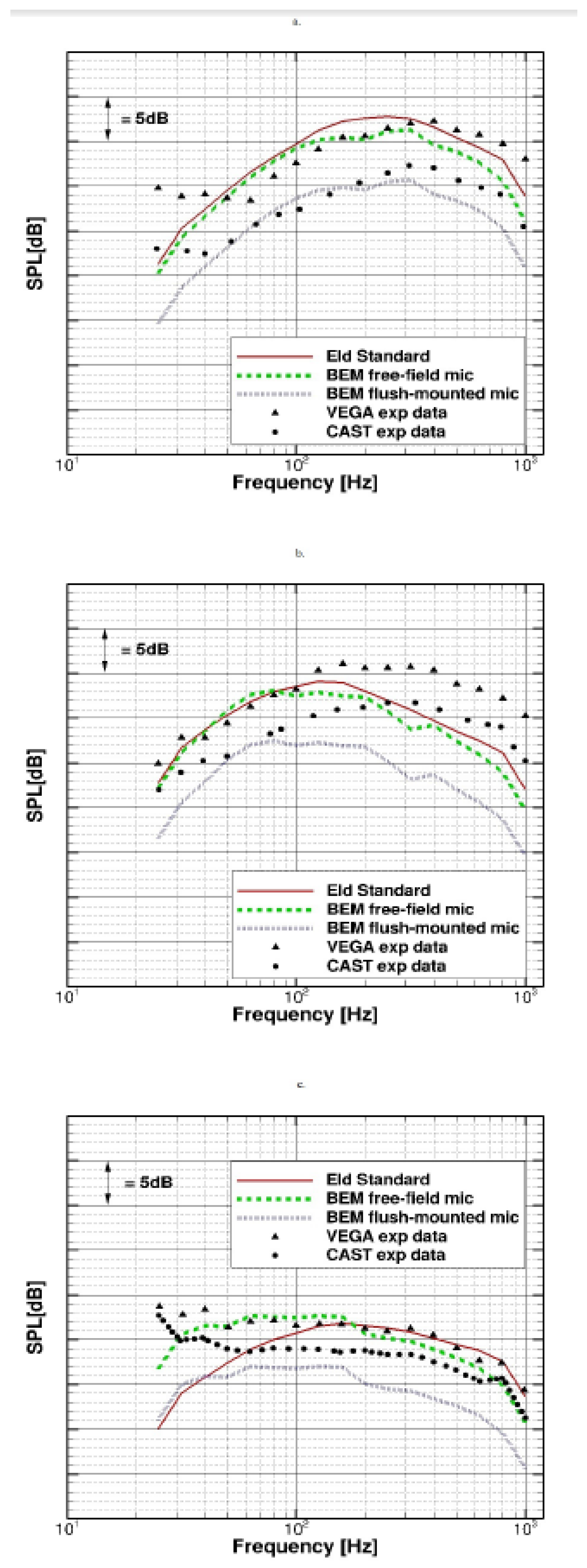
The free-field results achieved with the Eldred standard model and the Eldred-based uncorrelated and correlated models have been compared with the VEGA and CAST experimental results for three launcher altitudes (0, 10 and 75 m) in [
14]. The uncorrelated model has shown to provide a better prediction at 0 and 10 m, while the correlated model is better at 75 m, matching the experimental data with an uncertainty of about 5 dB.
The reason for the different matching between the correlated/uncorrelated models and the experiments’ data can be explained reasonably with the different turbulent mechanisms that occur at different altitudes. At 75 m, the launcher is far from the launching pad, and, as a consequence, the jet does not interact with the ground. Indeed, the turbulence structures are still unchanged, and the correlation is preserved. Because the correlated model is developed to reproduce the jet turbulent scales’ correlation, it is expected to be more suitable for reproducing the free jet conditions at the altitude of 75 m. Conversely, at the reduced distances of 0 and 10 m between the launcher and the launching pad, the jet turbulent structures are broken and mixed as a result of the interaction with the launching pad, and, as a consequence, the turbulent structures become more uncorrelated.
The effect of the launcher has thus been investigated with the hybrid approach. A three-dimensional multifrequency computation has been performed up to a maximum frequency of 1000 Hz, and the results have lastly been processed to achieve third-octave spectra. The uncorrelated model was used for 0 and 10 m, while the correlated model was used for 75 m. The output of this process was then passed as input to the hybrid procedure for analyzing the launcher response, as described in the following section.
The results of the BEM calculation are shown in
Figure 4, where they are compared, in terms of SPL, with the standard Eldred results and the data from the two experimental campaigns.
The SPL values have been computed in two sets of points, representing far- and near-field point. Far-field points, distant from the launcher by 15% of the nozzle diameter, have been dubbed in the figure as “free-field microphones”. Near-field points, selected on the rocket surface itself, are indicated as “flush-mounted microphones”. The gap observed between the free-field and the flush-mounted microphones resembles that occurring between the two experimental datasets, suggesting a different position of the microphone in the respective experimental set-up.
4.2. Vibroacoustic Analysis
The description of the hybrid model’s response to the external acoustic field and internal acoustic field generated at lift-off by the P120 engine are reported, respectively, in terms of an average acceleration and a root-mean-square (RMS) pressure.
The acceleration data are reported as band-limited RMS spectrum responses strictly associated to the frequency band selected for the analysis. In the analysis, the damping was assumed as constant on the frequency, and similar was assumed for all the structural (values set to 0.04) and the acoustic (values set to 0.001) subsystems. The response of some equipment is reported in
Figure 5 as an example.
For IS01, the acceleration levels were very high in the low frequency range. In particular, the main contribution to the vibration energy was clearly associated to the structure’s ring frequency, along with global modes’ impact occurring at a lower frequency; above ring frequencies, the acceleration levels attenuated significantly for almost all the equipment, with some high-frequency contributions derived from the coincidence frequencies effect. In general, the dynamics of the lumped masses simulating the equipment appears as confined to the low–mid frequency.
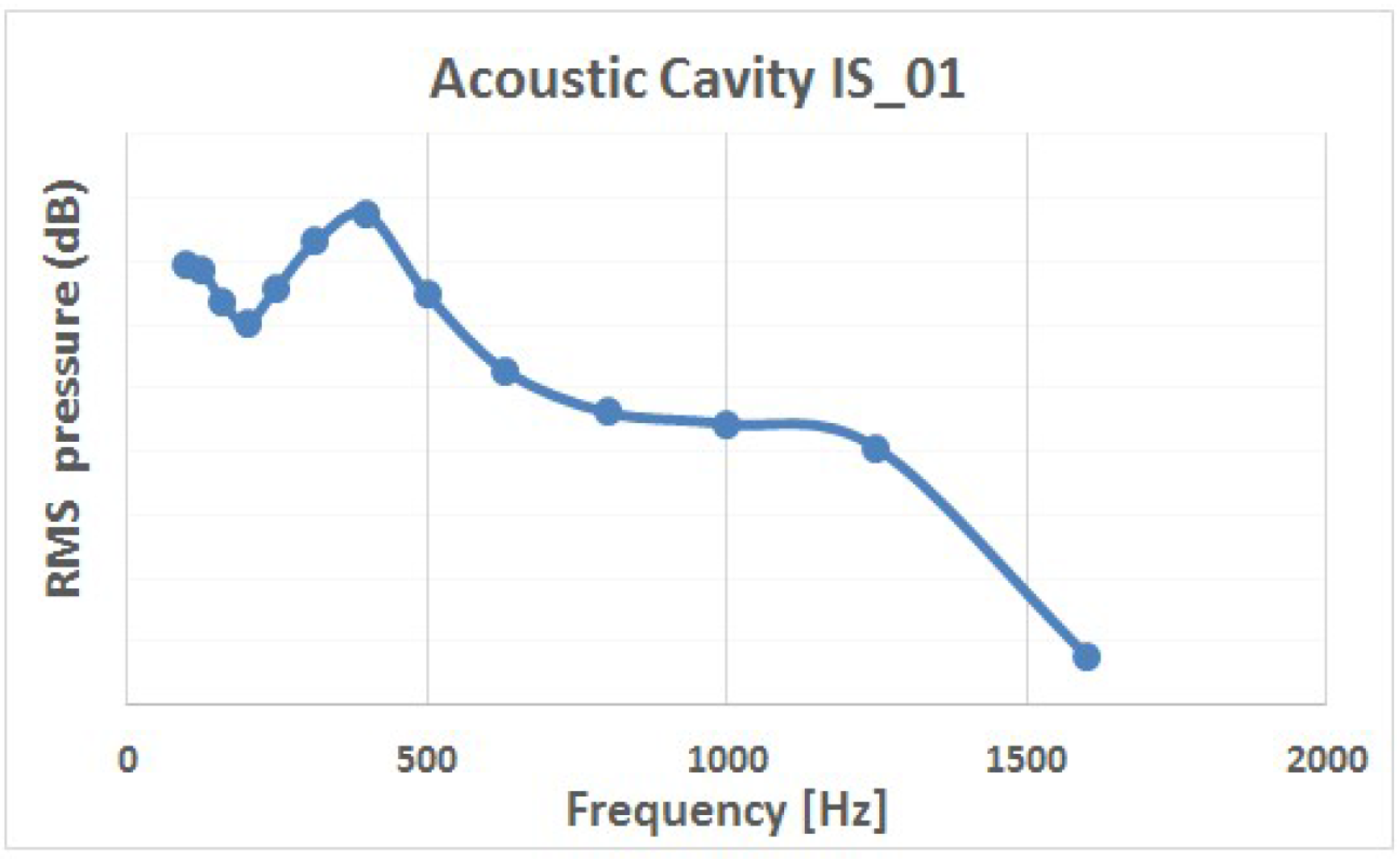
The average pressure level associated to the IS01 cavity is reported in
Figure 6, described in decibel values, referred to the band-limited RMS spectrum response, in which the reference pressure is the standard pressure value, 2 × 10
−5 Pa. The responses reflect the same distribution against the frequency of the structural interstage, with the higher energy concentrated at the characteristic frequency already identified for the structure.
5. Conclusions
An innovative, multi-domain verification process has been conceived and applied to the design of an enhanced version of the VEGA space launcher. The procedure has allowed a virtual, time- and cost-saving testing activity, developed by the prime contractor, Avio, in collaboration with CIRA SCpA.
The results are encouraging, and potentially the adoption of similar integrated and hybrid approaches can be foreseen in space and aviation industries.

 ,
, 


