Article

Numerical Investigation of the Equalization Enhanced Phase Noise Penalty for M-Quadrature Amplitude Modulation Formats in Short-Haul Few-Mode Fiber Transmission Systems with Time-Domain Equalization †

Photonic Network System Laboratory, National Institute of Information and Communications Technology (NICT), 4-2-1 Nukui Kitamachi, Koganei, Tokyo 184-8795, Japan
*
Author to whom correspondence should be addressed.
This paper is an extended version of our paper published in Advanced Photonics Congress(APC), New Orleans, LA, USA, 24–27 July 2017.
Appl. Sci. 2018, 8(11), 2182; https://doi.org/10.3390/app8112182
Submission received: 7 September 2018 / Revised: 1 November 2018 / Accepted: 2 November 2018 / Published: 7 November 2018
(This article belongs to the Special Issue DSP for Next Generation Fibre Communication Systems)

Abstract

:
The equalization enhanced phase noise (EEPN), caused by the interaction of the chromatic dispersion (CD) with the phase noise of the local oscillator (LO), has been extensively studied for single-mode optical communication systems. Few-mode fiber (FMF) transmission systems introduce a new channel impairment, the differential mode delay (DMD), which also creates EEPN and hence limits the maximum transmission distance of those systems. In this work, we numerically investigate the optical signal to noise ratio (OSNR) penalties caused by the EEPN in a 3-mode FMF transmission system at 25 GBd for quadrature phase-shift keying (QPSK), 16-quadrature amplitude modulation (QAM), 32-QAM and 64-QAM modulation formats when using the blind phase search (BPS) carrier phase recovery (CPR) algorithm, which has been demonstrated to be both robust and suitable for optical communication systems. Our numerical study assumes a short-span of FMF, modeled in the weakly-coupled regime, and includes two cases; the use of ideal mode-selective de/multiplexers at both ends of the FMF span (model A), and the use of ideal non-mode-selective de/multiplexers (model B). The results show that the EEPN has almost no effect in model A. However, EEPN produces a severe penalty in model B with the onset of the OSNR degradation starting for a DMD spread of the impulse response of about 100 symbols for all modulation formats investigated. The distribution ratio of the amount of phase noise between the transmitter and receiver lasers is also assessed for model B and we confirm that the degradation is mainly due to the phase noise of the LO.

1. Introduction

Coherent transmission systems using multi-mode fiber (MMFs), and in particular few-mode fiber (FMFs) as a subset thereof, have recently attracted much research attention due to the capacity enhancement enabled by transmitting multiple data streams on a set of orthogonal spatial modes [1,2,3]. The incorporation of digital signal processing (DSP) algorithms, including multiple-input multiple-output (MIMO) equalizers, enable the compensation in the digital domain of the differential mode delay (DMD) and the decoupling of the modes that were coupled both during propagation through the FMF channel and at the input/output multiplexing devices. Conversely, in incoherent optical communication systems, where DSP can be used with the squared modulus of the electrical field and not with the amplitude and phase thereof [4], the impairments caused by the MMF channel, e.g., the mode mixing/scrambling and the DMD, constitute a fundamental limitation to the system capacity and reach. Hence, incoherent MMF/FMF links that employ modulation formats such as ON-OFF keying (OOK) [5] or 4-way pulse amplitude modulation (PAM4) [6] are currently used predominantly for short reach applications. Without loss of generality, in this manuscript we focus on coherent FMF optical transmission systems as a particular case of MMF systems when the number of modes is small. In FMF systems, some authors claim that the DMD spread does not constitute a fundamental limitation because even large DMD spread values can be compensated with sufficiently large linear MIMO equalizers, although at a very high computational cost of the DSP circuitry [7]. However, in a practical implementation the phase noise in the transmitter and receiver lasers cannot be neglected and the interaction of the DMD with the phase noise of the local oscillator (LO) will cause equalization enhanced phase noise (EEPN), which may significantly degrade the system performance. The interaction of the DMD with the phase noise of the LO in FMF systems plays a similar role as the interaction of the chromatic dispersion (CD) with the phase noise of the LO in single-mode fiber (SMF) systems [8], and additionally in FMF transmission systems the CD also produces EEPN.
EEPN has been studied in detail for dispersion-uncompensated SMF systems with digital compensation of the CD. Shieh and Ho [9] studied the theoretical EEPN power penalty in SMF systems resulting from the interaction of the CD and the LO phase noise and found that the EEPN penalty increases for larger dispersion values and baud rates. Xie [10] numerically demonstrated, using quadrature phase-shift keying (QPSK) as the modulation format, that the EEPN penalty increases linearly with the baud rate. Lau et al. [11], both analytically and numerically, concluded that the effect of the EEPN induced phase noise is approximately twice as large as the EEPN induced amplitude noise, and also that the contribution of the transmitter phase noise is negligible compared to the LO for links with residual dispersion higher than 700 ps/nm. Xu [12] presented an analytical model for differential N-phase shift keying (PSK) systems and concluded that the EEPN performance degradation increases significantly with the increment of the LO phase noise, the fiber dispersion and the order of the modulation format. Kakkar et al. [13] conducted a frequency domain analysis and concluded that the EEPN penalty mainly originates from the low frequency noise components of the LO. The same authors [14] extended their analysis and concluded that the EEPN is similar to multi-path fading in wireless communication systems. Qiu et al. [15] demonstrated both numerically and experimentally that in systems with a Stokes-vector direct-detection (SV-DD) receiver the EEPN penalty increases with the LO laser linewidth, the accumulated dispersion and the order of the modulation format, and this penalty can be partially mitigated with a maximum-likelihood (ML) phase estimator.
Regarding the EEPN in FMF transmission systems, Shieh [16] analytically derived a simple expression for the signal to noise ratio (SNR) penalty, which grows linearly with the total amount of the DMD and the LO phase noise, for the worst case of total coupling between the two modes. Ho and Shieh [17] extended the analysis of [16] to include all the possible ensemble averages of the unitary matrices modeling the mode coupling in the strongly-coupled regime. Note that both analytical analyses assume perfect and instantaneous estimation of the phase noise, yet practical phase estimation algorithms [18] must average over a number of samples to remove noise from the estimated phase value. Liang et al. [19] experimentally showed that in a 28 GBd 3-mode QPSK system, duo-binary shaping combined with maximum likelihood sequence detection (MLSD) can relax the LO linewidth requirements due to EEPN. Secondini and Antonelli [20] numerically studied the digital coherence enhancement technique to mitigate the effects of EEPN in 3-mode FMF transmission systems.
In this work, we numerically assess the impact of the EEPN optical signal to noise ratio (OSNR) penalty on a typical 3-mode short-span FMF transmission link with M-quadrature amplitude modulation (QAM) formats at 25 GBd when using a MIMO time-domain equalizer. Time-domain MIMO equalizers are less efficient in terms of complexity than their frequency-domain counterparts [21]. However, time-domain equalizers update the equalizer taps at a much higher rate than frequency-domain equalizers and hence are more robust against quick variations in the phase noise. We consider a short-span of FMF which can be modeled in the weakly-coupled regime and include two models, model A and model B, to account for the use of mode-selective demultiplexer and multiplexer (DE/MUXs) [22] or non-mode-selective DE/MUXs [2] at both ends of the FMF. In both models, coupling of modes within a mode-group—for example, the X and Y polarizations of the LP 01 mode—is modeled with random complex unitary (RCUs) matrices. In our numerical simulations, we use the blind phase search (BPS) carrier phase recovery (CPR) algorithm, which has a high performance at a cost of an additional computational complexity compared to Viterbi and Viterbi-based CPR algorithms [23]. However, the BPS algorithm may be implemented in a hardware efficient way due to the absence of feedback loops [18]. The BPS parameters B—the number of test phases—and N—the number of averaged symbols—are carefully optimized to not bias the simulation results. Compared to our previous work [24], here we describe in detail the optimization procedure of the BPS CPR algorithm and extend the analysis to investigate the impact of the phase noise ratio between the transmitter and LO lasers for QPSK and 16-QAM modulation formats. The results show that the EEPN penalty is negligible for systems with mode-selective DE/MUXs with no crosstalk between mode-groups (model A). However, non-mode-selective DE/MUXs (model B), even for a short-span of FMF modeled in the weakly-coupled regime, induce a severe penalty due to the EEPN which makes the system phase noise requirements more stringent as the spread of the impulse response increases. The onset of the OSNR penalty in model B starts for a DMD impulse response spread of about 100 symbols for all modulation formats investigated. Furthermore, it is confirmed that to mitigate the EEPN penalty it is imperative that the LO has a very low phase noise compared with the transmitter laser phase noise.
The remainder of this paper is organized as follows. Section 2 describes the EEPN in the context of FMF transmission systems and the numerical model used in this study. Then, the numerical results are presented and discussed in Section 3. Finally, Section 4 summarizes and concludes the paper.

2. Problem Description, Simulation Model and Methodology

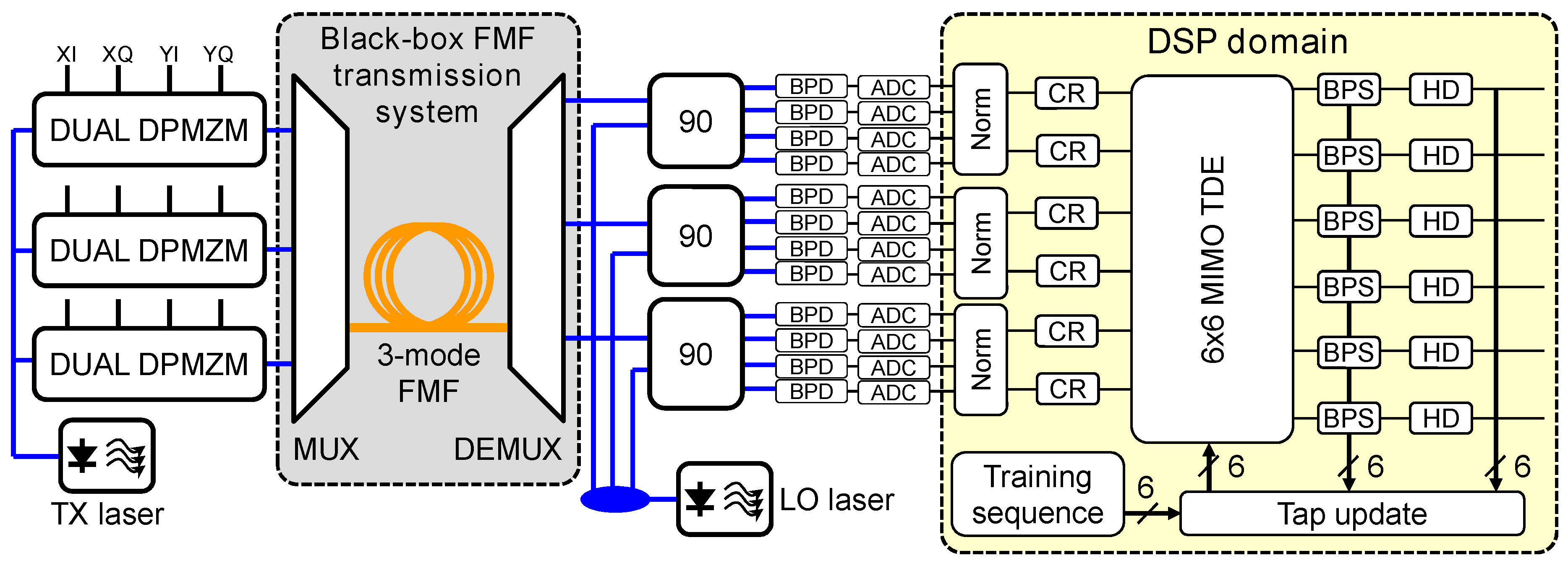
2.1. Few-Mode Fiber Transmission Systems Description

Figure 1 shows a diagram of the 3-mode FMF transmission system used as a model in this work. The transmitter consists of one laser used as light source that is split into three optical signals which are input to a set of three independent dual-polarization dual-parallel Mach-Zehnder modulator (DP-DPMZMs). Each DP-DPMZM generates a polarization-division multiplexing (PDM) M-QAM signal or stream to be carried on an orthogonal spatial channel. After modulation, a spatial multiplexer with three SMF inputs generates a linear combination of the three orthogonal modes in the FMF for each input stream. At the receiver, a demultiplexer couples three linear combinations of orthogonal modes present in the FMF into a set of three SMFs. We consider the multiplexer (MUX), the FMF and the demultiplexer (DEMUX) as a black box MIMO linear system with 3 single-mode inputs and 3 single-mode outputs, as remarked in Figure 1. Each SMF carries 2 polarizations that correspond to degenerate modes so the dimensions of the MIMO system are actually 6 × 6 over a complex space. The receiver consists of three polarization-diverse optical hybrids with four balanced photodiodes and digitizers each. The signal from a free-running laser used as LO is split into three equal parts and input to the optical hybrids and hence the phase noise in the three streams is equal and correlated. The receiver DSP first normalizes the signal and recovers the clock. Note that in this simulation it is not necessary to compensate for receiver imperfections like quadrature-skew or differential photodiode responsivities. After the clock recovery, the 6 complex signals are input to a complex 6 × 6 MIMO time-domain equalizer and CPR loop [25]. After CPR, the samples are hard-detected, used to compute the equalizer error-signal, and to update the taps with this error-signal. The equalizer loop initially uses a known training sequence to achieve convergence and then switches into blind decision-directed mode.
The response of the black-box in Figure 1 can be modeled as a matrix M ( ω ) , which includes the response of the MUX, the DEMUX and any linear impairments in the FMF transmission channel [17,26]. In general, M ( ω ) is a time-varying matrix, due to external perturbations like fiber movement and temperature changes, but we will consider it as a time-invariant matrix through the rest of the paper for simplicity. In a 3-mode FMF system, M ( ω ) is a complex square matrix with rank 6. If there are no losses or gains in the system, i.e., the energy at the input is the same as the energy at the output, then det M ( ω ) = ± 1 and M ( ω ) is unitary. Unitary matrices can be interpreted as rotational matrices with a possible reflection in a complex functional space. We can factorize the black-box response as,
M ( ω ) = O ( ω ) F ( ω ) I ( ω )
where F ( ω ) is the response of the FMF, I ( ω ) is the response of the MUX and O ( ω ) is the response of the DEMUX. The singular value decomposition (SVD) of a unitary matrix is not unique. However, imposing the condition that U ( ω ) must be independent of frequency to the first order, d U ( ω ) / d ω = 0 , then the columns of U ( ω ) are the input principal modes [26], which is a generalization into higher dimensions of the principal states of polarization in an SMF [27]. Taking into account this constraint, we can further factorize the response of the FMF into the unique principal modes,
M ( ω ) = O ( ω ) V ( ω ) Λ ( ω ) U * ( ω ) I ( ω )
where V ( ω ) and U ( ω ) are unitary matrices, * denotes conjugate transposition and Λ ( ω ) = diag [ a 1 ( ω ) , a 2 ( ω ) , , a 6 ( ω ) ] is a diagonal matrix with elements,
a n ( ω ) = exp g n 2 j ω τ n j ω 2 D n λ 2 L 4 π c
where g n R represents the mode losses or gains, τ n R the mode group delay and D n the mode CD, all of them with respect to the principal modes of the FMF. For simplicity, in this work we consider an unamplified system with no mode-dependant loss (MDL) and CD and hence g n = D n = 0 . The DMD is defined as the maximum temporal spread between the principal modes
DMD = | max ( τ n ) min ( τ n ) |
which corresponds to the temporal spread of the system impulse response. The complexity of the MIMO equalizer is directly proportional to this quantity. Step-index FMFs typically have large values of DMD, which produce clearly separated peaks in the impulse response [2]. Graded-index FMFs may be designed in such a way that the differential group delay of the principal modes is small [28,29] and hence the impulse response for these fibers may have peaks that totally overlap and result in a lower DMD spread.
A three mode FMF supports two mode-groups, LP 01 and LP 11 , with effective refractive indices n e f f 01 and n e f f 11 , respectively. The two modes belonging to the LP 01 group and the four modes of the LP 11 group are degenerated or quasi-degenerated and hence will always couple as the signal propagates through the FMF due to birefringence and other imperfections of the fiber [30], similarly to the polarization-mode dispersion (PMD) in single mode systems [27]. Depending on the properties of the matrix F ( ω ) with respect to the coupling between the two mode-groups, we can distinguish between the weakly-coupled FMF regime or the strongly-coupled FMF regime. The weakly-coupled regime, in its ideal case, is defined as,
F ( ω ) = a 11 ( ω ) a 12 ( ω ) 0 0 0 0 a 21 ( ω ) a 22 ( ω ) 0 0 0 0 0 0 b 11 ( ω ) b 12 ( ω ) b 13 ( ω ) b 14 ( ω ) 0 0 b 21 ( ω ) b 22 ( ω ) b 23 ( ω ) b 24 ( ω ) 0 0 b 31 ( ω ) b 32 ( ω ) b 33 ( ω ) b 34 ( ω ) 0 0 b 41 ( ω ) b 42 ( ω ) b 43 ( ω ) b 44 ( ω )
where the sub-matrices A ( ω ) and B ( ω ) , with elements a i j ( ω ) and b i j ( ω ) and dimensions 2 × 2 and 4 × 4 , respectively, are RCU matrices. In the ideal weakly-coupled regime there is no exchange of energy between the LP 01 and the LP 11 mode-groups. The FMF strongly-coupled regime is defined as
F ( ω ) = X ( ω )
where X ( ω ) is a RCU matrix with the energy of one input mode distributed equally among all the output modes and hence there is an energy exchange between the mode-groups. In an ideal FMF, with a perfectly circular core, no bending and no scattering, and whether is step-index or graded-index, there is no coupling between the mode-groups because of the different effective refractive indices of each mode-group. However, in a real FMF, coupling between the mode-groups may happen due to fiber bending [31], Rayleigh scattering, and core misalignments at splicing points [32,33]. Both the weakly- and strongly-coupled regimes describe ideal situations not found in real fibers. Real FMF transmission systems can be attributed to the intermediate-coupled regime [34], which depends on the total length L of the system and on the perturbations that introduce the mode coupling [31]. Real FMF systems with a relatively short L behave in the weakly-coupled regime but as the system length increases the behavior resembles the strongly-coupled regime. In spite of this, both the weakly- and strongly-coupled models are useful to investigate system behavioral boundaries as they are mathematically tractable and easy to simulate. For example, it has been shown that in the weakly-coupled regime, the DMD spread grows proportionally to the system distance L whereas in the strongly-coupled regime the DMD spread grows proportionally to L , whereas in real systems the DMD spread lies in between these two boundaries [32].
The concept of weakly- and strongly-coupled regimes can be applied to other few-mode optical components, such as the DE/MUXs. In the literature, spatial mode DE/MUXs are categorized into non-mode-selective and mode-selective. A MUX belonging to the former group is the non-mode selective photonic lantern [35], while the latter group is represented by mode-selective photonic lanterns [36], phase plates [37], planar lightwave circuit (PLC) based couplers [38], and tapered velocity couplers [39]. Mode-selective DE/MUXs can be ideally modeled with identity matrices and non-mode-selective DE/MUXs with RCU matrices.
The EEPN originates when the MIMO equalizer at the receiver has to pick signal components from time-shifted copies of the signal that have uncorrelated phase noise, originating at the LO laser, which translates into different rotations of the constellation that cannot be compensated by the CPR algorithm. In other words, the time-varying phase of the LO will be distributed along the coefficients of the linear equalizer [8]. In this work, we consider the system impulse response, consisting of the combined MUX, fiber and DEMUX responses, as a black box where the coupling originates at discrete points at the edges of the fiber and the only impairment caused by the fiber is a differential mode group delay. With respect to the EEPN, the variables of interest are the total temporal length of the system impulse response and the amount of phase noise of the LO, regardless of whether the actual mode mixing originates in the fiber or in the DE/MUXs.
Taking into account the weakly- and strongly-coupled regimes of the FMF and the nature of the DE/MUXs used, Figure 2a summarizes the most simple options to model a FMF transmission system. In this work, we focus on short-span systems where the FMF can be modeled in the weakly-coupled regime, as has been demonstrated experimentally many times in the literature [2,22,33], and investigate the OSNR penalty caused by the EEPN. In this simulation, it is assumed that the group velocity of the LP 11 mode-group is lower compared to the LP 01 mode-group and hence the LP 11 mode-group arrives later [40]. However, there are FMF designs where the LP 11 mode may arrive earlier [41]. We consider both mode-selective DE/MUXs and non-mode-selective DE/MUXs in two separate models named model A and model B, respectively. The impulse response of model A, demonstrated experimentally in [22], resembles Figure 2b where only the X-polarization constituents of the modes LP 01 and LP 11 a are plotted for clarity. The temporal distance between the two peaks shown in Figure 2b corresponds to the DMD spread. The impulse response of model B, demonstrated experimentally [2], resembles the example in Figure 2c. We leave the investigation of the EEPN penalty on the FMF strongly-coupled and intermediate-coupled regimes as a future work.

2.2. Numerical Simulation Description and Measurement Methodology

Figure 3 depicts a diagram of the numerical model developed to study the OSNR penalties caused by the EEPN for model A, corresponding to the system impulse response of Figure 2b, and model B, corresponding to the system impulse response of Figure 2c. After generating the 3 modulated and independent signals, the transmitter adds the same amount of multiplicative phase noise TX pn to each mode. In model B, the MUX was modeled with a rank 6 RCU matrix [42]. Mode- and polarization-independent additive white Gaussian noise (AWGN) was added to each polarization on each mode to set the desired OSNR. The fiber was modeled as a channel with ideal coupling within the mode-groups, null coupling between mode-groups and no CD with a rank 2 RCU matrix for the LP 01 mode-group and a rank 4 RCU matrix for the LP 11 mode-group. LP 11 a and LP 11 b modes were delayed with respect to LP 01 by τ 2 symbols to account for the link differential mode group delay. In model B, the DEMUX was modeled with a rank 6 RCU matrix. Finally, the receiver added the same multiplicative phase noise RX pn to each mode due to the LO. In model A, the DE/MUXs were assumed to be ideal mode-selective, i.e., no mode coupling at all, and were modeled with rank 6 identity matrices.
The simulated baud rate was 25 GBd and a pseudo-random binary sequence (PRBS) of order 15 was used with all the combinations of quadratures, polarizations and modes, decorrelated with each other over at least 1111 symbols, which was longer than the maximum DMD spread under study to avoid equalization artifacts. The receiver DSP chain, as depicted in Figure 1, consisted of signal normalization, clock recovery, time-domain equalization-CPR loop, hard-detection and error counting. Each synthetic data trace, shown in Figure 4a, consisted of 131,072 symbols. Before equalization, 8192 symbols were stripped at the beginning and at the end to discard erroneous data introduced by circular convolutions. The equalizer was a complex 2 taps-per-symbol 6 × 6 time-domain equalizer [25] using the BPS CPR algorithm [18], where taps were updated on each symbol which enables high tracking speed of the phase noise. The equalizer taps were initially updated with a training sequence for the first 8192 symbols and then the equalizer was switched to decision-directed mode, where the error signal was computed with the hard-detected symbols. In order to avoid any simulation bias due to equalizer poor convergence or singularities, the equalizer initial taps were initialized with the inverse of the channel response, which was random for each realization. Note that the frequency offset was null. Before hard-detection, 16,384 and 8192 symbols were stripped at the beginning and at the end, respectively, to avoid errors due to equalizer pre-convergence and CPR, respectively. Data traces having carrier phase cycle slips were discarded. The cycle slip detector operated by first dividing the received bit-stream into blocks and counting the number of errors per block. The cycle slip detector was triggered if the number of errors in any block were greater than a threshold.
To save simulation time, the equalizer length was optimized for each simulated DMD value to L sym = L DMD + 2 G l + 1 symbols, where L DMD is the DMD value in symbol units and G l is a guard band of 8 symbols. The number of taps of the equalizer is hence L taps = 2 × L sym . As shown in Figure 4b, the training sequence was shifted forward by DMD / 2 symbols and hence the equalizer frequency response—the estimated inverse of the channel impulse response—did not overflow the equalizer length. For any phase noise and DMD value under study, the OSNR was swept in 0.5 dB intervals and the bit-error rate (BER) vs OSNR curves were linearly interpolated to compute the penalties at a BER = 10 4 by averaging the results of 3 independent realizations. The maximum OSNR penalty computed was 5 dB, corresponding to the cases where the impairments were so severe that the BER vs OSNR curve was greater than 10 4 for all OSNR values and hence the intersection point did not exist.

3. Numerical Results and Discussion

3.1. Simulator Calibration and Optimization of the BPS Number of Phases

In order to verify the correct operation of the simulator, initially a SMF transmission system was simulated at 10 GBd using a trace format similar to the one shown in Figure 4a. Figure 5 shows the OSNR penalty as a function of the phase noise, in units of linewidth times the symbol duration, as a function of the number of test phases B { 8 , 16 , 32 , 64 } of the BPS algorithm, for (left) QPSK and 16-QAM modulations and (right) for 32-QAM and 64-QAM modulation formats. Note that in this simulation the phase noise between of transmitter laser and the LO was identical and corresponding to the value in the X-axis. The OSNR penalties were calculated with respect to the theoretical curves and hence the simulator implementation penalty was about 0.5 dB for QPSK and 16-QAM, and approximately 1 dB for 32-QAM and 64-QAM.
For all modulation formats, the general trend is that increasing the number of test phases B reduces the OSNR penalty regardless of the phase noise. However, for sufficiently large values of B the penalty does not reduce any further. In addition, constellations with fewer number of symbols require less number of test phases B. These results approximately agree with the ones in Figure 7 of [18] and confirm the correct operation of the simulator, and in particular of the equalizer-CPR loop which is the most critical component. Furthermore, to reduce the complexity of the equalizer-CPR loop a value of B as low as possible is desirable. B = 32 was chosen for all subsequent simulations in this work, which introduces a small penalty for all the modulation formats investigated.

3.2. Optimization of the BPS Filter Length

After the optimization of the BPS number of phases B = 32 , the next step was to investigate the optimum length N of the BPS algorithm averaging filter. The model A simulator, at a baud rate of 25 GBd, was used to compute the OSNR penalty by sweeping both the phase noise and the BPS filter length N. Figure 6 shows the results for 16-QAM and 64-QAM modulation formats. QPSK and 32-QAM formats yielded similar results and are not plotted here to save space. For both modulation formats shown, N < 6 produces a high penalty because of the inability of the BPS algorithm to produce good phase estimates due to large estimation noise. Larger values of N produce good phase estimates and hence lower penalties. However, for a fixed value of the phase noise, large values of N yield larger penalties due to the inability of the filter to track quick changes of the phase noise. The larger the phase noise, the lower the filter length N should be to produce optimum phase estimates. As a compromise, we choose the optimum value of N = 10 for all subsequent simulations.

3.3. EEPN Penalty for M-QAM Formats and Equal Phase Noise in the Transmitter and Receiver Lasers

The numerical results for the OSNR penalty for model A are shown on Figure 7 for QPSK, 16-QAM, 32-QAM and 64-QAM modulation formats. The number of the BPS test phases was B = 32 , the length of the averaging filter was N = 10 , and the baud rate was 25 GBd. For a constant value of the DMD spread, all formats exhibit almost no degradation as the phase noise per laser increases. Note that for all modulation formats, the maximum linewidth of 4 MHz, 800 kHz, 400 kHz and 190 kHz per laser, respectively, is within the range that the BPS algorithm can compensate with the chosen parameters B and N. However, a small degradation in performance is observed as the DMD value increases and the cause for this may be due to the use of longer equalizers. A sparse MIMO equalizer [2,43] may help to alleviate this penalty but such analysis is beyond the scope of this work.
Figure 8 shows the results for model B and the aforementioned modulation formats. In contrast to model A, all modulation formats are severely degraded as the phase noise increases due to EEPN. Interestingly, for all modulation formats the onset of the penalty degradation corresponds to a DMD threshold value of about 100 symbols.

3.4. Distribution of the Phase Noise Between the Transmitter and Receiver Lasers

The results presented in Section 3.1, Section 3.2 and Section 3.3 had the same amount of phase noise in the transmitter and LO, which corresponds to the value of the X-axis in the plots and it is the typical case in FMF transmission experimental demonstrations. In this section we investigate the effect of varying the amount of phase noise between the transmitter and the LO when using model B for QPSK and 16-QAM modulation formats and the results are shown in Figure 9 and Figure 10, respectively. Both figures are plotted for ratios ρ { 0 , 0.25 , 0 . 6 ^ , 1.5 , 4 , } where ρ stands for the ratio ρ = TX pn / RX pn , where TX pn is the phase noise of the transmitter and RX pn is the phase noise of the receiver, and ρ = means all the phase noise in the system is contributed by the transmitter and the receiver is an ideal noiseless laser.
The analysis of both figures reveals that as ρ increases, i.e., the transmitter becomes noisier compared to the receiver, the behavior of the systems tends to the model A behavior even in the presence of strong coupling at the DE/MUXs. Conversely, as ρ decreases, the system tends to the model B behavior of the previous section. The conclusion is that the EEPN originates due to the phase noise contribution of the LO and hence it is important to keep the noise of the LO laser as low as possible in order to optimize the system performance.

4. Conclusions

We have numerically investigated the impact of the EEPN, in terms of the OSNR penalty, in a 25 GBd 3-mode short-span FMF transmission system where the FMF is modeled in the weakly-coupled regime, for QPSK, 16-QAM, 32-QAM and 64-QAM modulation formats as a function of the link DMD spread and the transmitter and receiver lasers phase noise. The fundamental receiver subsystem was a time-domain equalizer and carrier phase recovery loop with optimized number of test phases B = 32 and filter length N = 10 . In our study, we have considered the models A and B, corresponding to the case of ideal, full mode-selective couplers and ideal, non-mode-selective couplers, respectively. Furthermore, we have also investigated the effect of the distribution of the phase noise between the transmitter and receiver for QPSK and 16-QAM modulations and model B. The parameters of the BPS CPR algorithm were carefully optimized to avoid any biasing of the results, i.e., a sub-optimal operation of the CPR algorithm may be mistaken as a EEPN-caused penalty.
The results reveal that the EEPN has a negligible penalty for model A—mode-selective couplers and weakly-coupled FMF. However, in model B, which assumes non-mode-selective couplers and weakly-coupled FMF, the EEPN penalty quickly grows as the DMD spread of the optical link increases for a given per-laser phase noise value, which may limit the maximum transmission distance of FMF transmission systems. Furthermore, we note that if the impulse response of the non-mode-selective MUX in model B, I ( ω ) , is characterized a priori then a compensation by using I 1 ( ω ) in the digital domain may be performed at the transmitter to mitigate the effect of the EEPN. However, such a characterization is complex and time-consuming, requires the isolation of the non-mode-selective MUX during the characterization process [33], and on top of that, the frequency response may change over time due to environmental effects like temperature changes, which altogether renders this solution rather impractical in a real transmission system. For all M-QAM modulation formats analyzed, the onset of the penalty degradation is for a DMD of approximately 100 symbols. Furthermore, the results indicate that the EEPN penalty has a strong dependence on the amount of phase noise of the LO and hence noisier LOs have a larger impact on the system performance. The analysis of the combined effects of both the CD and the DMD in terms of the EEPN OSNR penalty, the modeling of the FMF in the strongly-coupled and intermediate-coupled regimes, and the impact of frequency-domain MIMO equalization—which is more computationally efficient but less able to track the phase noise compared with time-domain equalization—are left as future work.

Author Contributions

Conceptualization, J.M.D.M. and W.K.; Methodology, J.M.D.M.; Software, J.M.D.M.; Simulation and Data Preparation, J.M.D.M.; Writing—Original Draft Preparation, J.M.D.M.; Writing—Review & Editing, J.M.D.M., W.K., J.S., S.S., H.F., Y.A., N.W.; Supervision, J.S, S.S., H.F., Y.A., N.W.; Project Administration, S.S., H.F., Y.A., N.W.

Funding

This research received no external funding.

Conflicts of Interest

The authors declare no conflict of interest.

Abbreviations

The following abbreviations are used in this manuscript:
AWGNadditive white Gaussian noise
BERbit-error rate
BPSblind phase search
CDchromatic dispersion
CPRcarrier phase recovery
DEMUXdemultiplexer
DE/MUXdemultiplexer and multiplexer
DE/MUXdemultiplexers and multiplexers
DMDdifferential mode delay
DMTdiscrete multi-tone
DP-DPMZMdual-polarization dual-parallel Mach-Zehnder modulator
DSPdigital signal processing
EEPNequalization enhanced phase noise
FMFfew-mode fiber
LOlocal oscillator
MDLmode-dependant loss
MIMOmultiple-input multiple-output
MLmaximum-likelihood
MLSDmaximum likelihood sequence detection
MMFmulti-mode fiber
MUXmultiplexer
MUXmultiplexers
OOKON-OFF keying
OSNRoptical signal to noise ratio
PAM44-way pulse amplitude modulation
PDMpolarization-division multiplexing
PMDpolarization-mode dispersion
PhPphase plate
PLphotonic lantern
PLCplanar lightwave circuit
PRBSpseudo-random binary sequence
PSKphase shift keying
QAMquadrature amplitude modulation
QPSKquadrature phase-shift keying
RCUrandom complex unitary
SMFsingle-mode fiber
SNRsignal to noise ratio
SVDsingular value decomposition
SV-DDStokes-vector direct-detection

References

  1. Richardson, D.J.; Fini, J.M.; Nelson, L.E. Space-division multiplexing in optical fibres. Nat. Photonics 2013, 7, 354–362. [Google Scholar] [CrossRef] [Green Version]
  2. Sakaguchi, J.; Klaus, W.; Delgado Mendinueta, J.M.; Puttnam, B.J.; Luís, R.S.; Awaji, Y.; Wada, N.; Hayashi, T.; Nakanishi, T.; Watanabe, T.; et al. Large Spatial Channel (36-Core × 3 mode) Heterogeneous Few-Mode Multicore Fiber. J. Lightw. Technol. 2016, 34, 93–103. [Google Scholar] [CrossRef]
  3. Rademacher, G.; Ryf, R.; Fontaine, N.K.; Chen, H.; Essiambre, R.J.; Puttnam, B.J.; Luís, R.S.; Awaji, Y.; Wada, N.; Gross, S.; et al. Long-Haul Transmission Over Few-Mode Fibers With Space-Division Multiplexing. J. Lightw. Technol. 2018, 36, 1382–1388. [Google Scholar] [CrossRef]
  4. Kikuchi, K. Fundamentals of Coherent Optical Fiber Communications. J. Lightw. Technol. 2016, 34, 157–179. [Google Scholar] [CrossRef]
  5. Karinou, F.; Stojanovic, N.; Daly, A.; Neumeyr, C.; Ortsiefer, M. 1.55-μm Long-Wavelength VCSEL-Based Optical Interconnects for Short-Reach Networks. J. Lightw. Technol. 2016, 34, 2897–2904. [Google Scholar] [CrossRef]
  6. Motaghiannezam, S.M.R.; Tatarczak, A.; Chen, H.; Tatum, J.; Kocot, C. 51.56 Gbps PAM4 Transmission over up to 2.3 km OM4 Fiber using Mode Selective VCSEL. In Proceedings of the Optical Fiber Communication Conference and Exhibition (OFC), San Diego, CA, USA, 11–15 March 2018. [Google Scholar]
  7. Fontaine, N.K. Characterization of multi-mode fibers and devices for MIMO communications. In Proceedings of the Next-Generation Optical Communication: Components, Sub-Systems, and Systems III, San Diego, CA, USA, 1–6 February 2014. [Google Scholar]
  8. Ip, E.; Kahn, J. Fiber Impairment Compensation Using Coherent Detection and Digital Signal Processing. J. Lightw. Technol. 2010, 28, 502–519. [Google Scholar] [CrossRef]
  9. Shieh, W.; Ho, K.P. Equalization-enhanced phase noise for coherent-detection systems using electronic digital signal processing. Opt. Express 2008, 16, 15718–15727. [Google Scholar] [CrossRef] [PubMed]
  10. Xie, C. Local Oscillator Phase Noise Induced Penalties in Optical Coherent Detection Systems Using Electronic Chromatic Dispersion Compensation. In Proceedings of the Optical Fiber Communication Conference and Exhibition (OFC), San Diego, CA, USA, 22–26 March 2009. [Google Scholar]
  11. Lau, A.P.T.; Shen, T.S.R.; Shieh, W.; Ho, K.P. Equalization-enhanced phase noise for 100 Gb/s transmission and beyond with coherent detection. Opt. Express 2010, 18, 17239–17251. [Google Scholar] [CrossRef] [PubMed]
  12. Xu, T.; Jacobsen, G.; Popov, S.; Li, J.; Sergeyev, S.; Friberg, A.T.; Zhang, Y. Analytical BER performance in differential n-PSK coherent transmission system influenced by equalization enhanced phase noise. Opt. Commun. 2015, 334, 222–227. [Google Scholar] [CrossRef] [Green Version]
  13. Kakkar, A.; Schatz, R.; Pang, X.; Navarro, J.R.; Louchet, H.; Ozolins, O.; Jacobsen, G.; Popov, S. Impact of local oscillator frequency noise on coherent optical systems with electronic dispersion compensation. Opt. Express 2015, 23, 11221–11226. [Google Scholar] [CrossRef] [PubMed]
  14. Kakkar, A.; Navarro, J.R.; Schatz, R.; Louchet, H.; Pang, X.; Ozolins, O.; Jacobsen, G.; Popov, S. Comprehensive Study of Equalization-Enhanced Phase Noise in Coherent Optical Systems. J. Lightw. Technol. 2015, 33, 4834–4841. [Google Scholar] [CrossRef]
  15. Qiu, M.; Zhuge, Q.; Sowailem, M.Y.S.; Hoang, T.M.; Chagnon, M.; Xiang, M.; Zhou, X.; Zhang, F.; Plant, D.V. Equalization-Enhanced Phase Noise in Stokes-Vector Direct Detection Systems. IEEE Photon. J. 2016, 8, 7907307. [Google Scholar] [CrossRef]
  16. Shieh, W. Interaction of Laser Phase Noise with Differential-Mode-Delay in Few-mode Fiber Based MIMO Systems. In Proceedings of the Optical Fiber Communication Conference and Exhibition (OFC), Los Angeles, CA, USA, 4–8 March 2012. [Google Scholar]
  17. Ho, K.P.; Shieh, W. Equalization-Enhanced Phase Noise in Mode-Division Multiplexed Systems. J. Lightw. Technol. 2013, 31, 2237–2243. [Google Scholar]
  18. Pfau, T.; Hoffmann, S.; Noe, R. Hardware-Efficient Coherent Digital Receiver Concept With Feedforward Carrier Recovery for M-QAM Constellations. J. Lightw. Technol. 2009, 27, 989–999. [Google Scholar] [CrossRef]
  19. Liang, J.; Fu, S.; Tang, M.; Shum, P.; Liu, D. Mitigation of Equalization Enhanced Phase Noise in Weakly Coupled FMF Transmission by Receiver Side Duo-binary Shaping and MLSD. In Proceedings of the 41st European Conference and Exhibition on Optical Communications (ECOC), Valencia, Spain, 27 September–1 October 2015. [Google Scholar]
  20. Secondini, M.; Antonelli, C. Digital Coherence Enhancement in Space-Division Multiplexed Transmission. In Proceedings of the 43rd European Conference and Exhibition on Optical Communications (ECOC), Gothenburg, Sweden, 17–21 September 2017. [Google Scholar]
  21. Inan, B.; Spinnler, B.; Ferreira, F.; van den Borne, D.; Lobato, A.; Adhikari, S.; Sleiffer, V.A.J.M.; Kuschnerov, M.; Hanik, N.; Jansen, S.L. DSP complexity of mode-division multiplexed receivers. Opt. Express 2012, 20, 10859–10869. [Google Scholar] [CrossRef] [PubMed]
  22. Igarashi, K.; Wakayama, Y.; Soma, D.; Tsuritani, T.; Morita, I.; Park, K.J.; Ko, J.; Kim, B.Y. Low-loss and Low-crosstalk All-fiber-based Six-mode Multiplexer and Demultiplexer for Mode-Multiplexed QAM Signals in C-band. In Proceedings of the Optical Fiber Communication Conference and Exhibition (OFC), San Diego, CA, USA, 11–15 March 2018. [Google Scholar]
  23. Bilal, S.M.; Bosco, G.; Cheng, J.; Lau, A.P.T.; Lu, C. Carrier Phase Estimation Through the Rotation Algorithm for 64-QAM Optical Systems. J. Lightw. Technol. 2015, 33, 1766–1773. [Google Scholar] [CrossRef] [Green Version]
  24. Delgado Mendinueta, J.M.; Klaus, W.; Sakaguchi, J.; Awaji, Y.; Wada, N. Equalization Enhanced Phase Noise Penalties for QPSK/16QAM Modulations in Few-Mode Fiber Transmission with Time-Domain MIMO Equalization. In Proceedings of the OSA Advanced Photonics Congress (APC), New Orleans, LA, USA, 24–27 July 2017. [Google Scholar]
  25. Randel, S.; Ryf, R.; Sierra, A.; Winzer, P.J.; Gnauck, A.H.; Bolle, C.A.; Essiambre, R.J.; Peckham, D.W.; McCurdy, A. 6 × 56-Gb/s mode-division multiplexed transmission over 33-km few-mode fiber enabled by 6 × 6 MIMO equalization. Opt. Express 2011, 19, 16697–16707. [Google Scholar] [CrossRef] [PubMed]
  26. Ho, K.P.; Kahn, J.M. Linear Propagation Effects in Mode-Division Multiplexing Systems. J. Lightw. Technol. 2014, 32, 614–628. [Google Scholar] [CrossRef]
  27. Gordon, J.P.; Kogelnik, H. PMD fundamentals: Polarization mode dispersion in optical fibers. Proc. Natl. Acad. Sci. USA 2000, 97, 4541–4550. [Google Scholar] [CrossRef] [PubMed] [Green Version]
  28. Maruyama, R.; Kuwaki, N.; Matsuo, S.; Ohashi, M. Two mode optical fibers with low and flattened differential modal delay suitable for WDM-MIMO combined system. Opt. Express 2014, 22, 14311–14321. [Google Scholar] [CrossRef] [PubMed]
  29. Ip, E.; Li, M.J.; Bennett, K.; Huang, Y.K.; Tanaka, A.; Korolev, A.; Koreshkov, K.; Wood, W.; Mateo, E.; Hu, J.; et al. 146λ× 6 × 19-Gbaud Wavelength-and Mode-Division Multiplexed Transmission Over 10 × 50-km Spans of Few-Mode Fiber With a Gain-Equalized Few-Mode EDFA. J. Lightw. Technol. 2014, 32, 790–797. [Google Scholar] [CrossRef]
  30. Klaus, W.; Imamura, K.; Sugizaki, R.; Awaji, Y.; Wada, N. Modal Properties of Perturbed Few-Mode Optical Fibers. Proceedings of Frontiers in Optics (FiO), Rochester, New York, USA, 17–21 October 2016. [Google Scholar]
  31. Carrero, C.C.C.; Molin, D.; Bigot-Astruc, M.; Bigot, L.; Quiquempois, Y.; Sillard, P. Group Delay Spread in Graded-Index 10-Spatial-Mode Fibers. In Proceedings of the 42nd European Conference and Exhibition on Optical Communications (ECOC), Dusseldorf, Germany, 18–22 September 2016. [Google Scholar]
  32. Ferreira, F.; Sygletos, S.; Ellis, A. Impact of Linear Mode Coupling on the Group Delay Spread in Few-Mode Fibers. In Proceedings of the Optical Fiber Communication Conference and Exhibition (OFC), Anaheim, CA, USA, 20–24 March 2015. [Google Scholar]
  33. Rommel, S.; Delgado Mendinueta, J.M.; Klaus, W.; Sakaguchi, J.; Vegas Olmos, J.J.; Awaji, Y.; Monroy, I.T.; Wada, N. Few-mode fiber, splice and SDM component characterization by spatially-diverse optical vector network analysis. Opt. Express 2017, 25, 22347–22361. [Google Scholar] [CrossRef] [PubMed]
  34. Ferreira, F.M.; Suibhne, N.M.; Sygletos, S.; Ellis, A.D. Few-Mode Fibre Group-Delays with Intermediate Coupling. In Proceedings of the 41st European Conference and Exhibition on Optical Communications (ECOC), Valencia, Spain, 27 September–1 October 2015. [Google Scholar]
  35. Fontaine, N.K. Photonic Lantern Spatial Multiplexers in Space-Division Multiplexing. In Proceedings of the Summer Topical Meetings, Waikoloa, HI, USA, 8–10 July 2013. [Google Scholar]
  36. Huang, B.; Fontaine, N.K.; Ryf, R.; Guan, B.; Leon-Saval, S.G.; Shubochkin, R.; Sun, Y.; Lingle, R., Jr.; Li, G. All-fiber mode-group-selective photonic lantern using graded-index multimode fibers. Opt. Express 2015, 23, 224–234. [Google Scholar] [CrossRef] [PubMed]
  37. Labroille, G.; Denolle, B.; Jian, P.; Genevaux, P.; Treps, N.; Morizur, J.F. Efficient and mode selective spatial mode multiplexer based on multi-plane light conversion. Opt. Express 2014, 22, 15599–15607. [Google Scholar] [CrossRef] [PubMed]
  38. Hanzawa, N.; Saitoh, K.; Sakamoto, T.; Matsui, T.; Tsujikawa, K.; Fujisawa, T.; Ishizaka, Y.; Yamamoto, F. Demonstration of PLC-based six-mode multiplexer for mode division multiplexing transmission. In Proceedings of the 41st European Conference and Exhibition on Optical Communications (ECOC), Valencia, Spain, 27 September–1 October 2015. [Google Scholar]
  39. Riesen, N.; Love, J.D. Tapered Velocity Mode-Selective Couplers. J. Lightw. Technol. 2013, 31, 2163–2169. [Google Scholar] [CrossRef]
  40. Kono, N.; Ito, F.; Iida, D.; Manabe, T. Impulse Response Measurement of Few-Mode Fiber Systems by Coherence-Recovered Linear Optical Sampling. J. Lightw. Technol. 2017, 35, 4392–4398. [Google Scholar] [CrossRef]
  41. Rommel, S.; Mendinueta, J.M.D.; Klaus, W.; Sakaguchi, J.; Olmos, J.J.V.; Awaji, Y.; Monroy, I.T.; Wada, N. Measurement of Modal Dispersion and Group Delay in a Large Core Count Few-Mode Multi-Core Fiber. In Proceedings of the 44th European Conference and Exhibition on Optical Communications (ECOC), Roma, Italy, 23–27 September 2018. [Google Scholar]
  42. Ozols, M. How to Generate a Random Unitary Matrix; Technical Report; Maris Ozols: Amsterdam, The Netherlands, 2009. [Google Scholar]
  43. Shi, K.; Thomsen, B.C. Sparse Adaptive Frequency Domain Equalizers for Mode-Group Division Multiplexing. J. Lightw. Technol. 2015, 33, 311–317. [Google Scholar] [CrossRef] [Green Version]
Figure 1. Schematic diagram of a typical optical transmission system consisting of a few-mode fiber supporting 6 spatial channels (2 mode-groups and 6 orthogonal modes). X polarization in-phase component (XI), X polarization quadrature component (XQ), Y polarization in-phase component (YI), Y polarization quadrature component (YQ), dual-parallel Mach-Zehnder modulator (DPMZM), transmitter (TX), multiplexer (MUX), demultiplexer (DEMUX), balanced photodiode (BPD), analog to digital converted (ADC), local oscillator (LO), digital signal processing (DSP), normalization (NORM), clock recovery (CR), multiple-input multiple-output (MIMO), time-domain equalizer (TDE), blind phase search (BPS), hard-detection (HD).
Applsci 08 02182 g001
Figure 2. (a) Diagram of the simple modeling cases in an FMF transmission system. (b) Simplified weakly-coupled FMF impulse response when there is no mode mixing in the fiber and mode-selective DE/MUXes are used (model A). Differential mode delay (DMD). (c) Weakly-coupled FMF frequency response with non-mode-selective DE/MUXes (model B). On both examples (b,c), only the X polarization for LP 01 and LP 11 a modes is plotted for clarity.
Applsci 08 02182 g002
Figure 3. Simplified simulation diagram for model A and model B. In model A, the MUX and DEMUX are modeled with rank 6 identity matrices whereas in model B the DE/MUXes are modeled with rank 6 random complex unitary matrices. Additive white Gaussian noise (AWGN), receiver (RX).
Applsci 08 02182 g003
Figure 4. (a) Diagram of a simulated data trace, showing the symbols stripped to avoid errors due to circular convolutions and the traning sequence. (b) Configuration of the equalizer to optimize the numbers of taps and hence reduce the simulation time.
Applsci 08 02182 g004
Figure 5. Phase noise penalties for a single-mode fiber (SMF) transmission system (1 mode) and the BPS algorithm for (left) quadrature phase-shift keying (QPSK) and 16-quadrature amplitude modulation (QAM) modulation formats and (right) 32-QAM and 64-QAM modulation formats.
Applsci 08 02182 g005
Figure 6. Optimization of the BPS algorithm filter length N using model A simulator for (left) 16-QAM and (right) 64-QAM modulation formats. Both plots show the optical signal to noise ratio (OSNR) penalty in dB computed at a bit-error rate (BER) of 10 4 .
Applsci 08 02182 g006
Figure 7. OSNR penalties in dB, computed at a BER of 10 4 , for model A and QPSK, 16-QAM, 32-QAM and 64-QAM modulation formats.
Applsci 08 02182 g007
Figure 8. OSNR penalties in dB, computed at a BER of 10 4 , for model B and QPSK, 16-QAM, 32-QAM and 64-QAM modulation formats.
Applsci 08 02182 g008
Figure 9. OSNR penalties in dB, computed at a BER of 10 4 , for QPSK modulation and model B for several distributions of the phase noise between the transmitter and receiver lasers.
Applsci 08 02182 g009
Figure 10. OSNR penalties in dB, computed at a BER of 10 4 , for 16-QAM modulation and model B for several distributions of the phase noise between the transmitter and receiver lasers.
Applsci 08 02182 g010

