Brazing Ti-48Al-2Nb-2Cr Alloys with Cu-Based Amorphous Alloy Filler
by
 , and
, and
Gang Wang
1,2,* ,
,
Peng Wu
1,
Wei Wang
3,
Dongdong Zhu
4,*,
Caiwang Tan
5,
Yongsheng Su
1,
Xinying Shi
2 and
Wei Cao
2 1
School of Mechanical and Automotive Engineering, Anhui Polytechnic University, Wuhu 241000, China
2
Nano and Molecular Systems Research Unit, University of Oulu, P.O. Box 3000, FIN-90014 Oulu, Finland
3
School of Mechanical Engineering, Anhui Machine and Electricity College, Wuhu 241002, China
4
School of Mechanical Engineering, Quzhou University, Quzhou 324000, China
5
State Key Laboratory of Advanced Welding and Joining, Harbin Institute of Technology, Harbin 150001, China
*
Authors to whom correspondence should be addressed.
Appl. Sci. 2018, 8(6), 920; https://doi.org/10.3390/app8060920
Submission received: 4 May 2018
/
Revised: 25 May 2018
/
Accepted: 30 May 2018
/
Published: 4 June 2018
(This article belongs to the Special Issue Bulk Metallic Glasses and Their Composites)
Abstract
:Featured Application
The results of present work will provide the possibility for the preparation of TiAl alloy shaped parts and expand the application area of amorphous alloys.
Abstract
In this work, the Ti-48Al-2Nb-2Cr (at. %) alloy was successfully brazed using a Cu-based amorphous filler in 600 s under varied brazing temperatures. The element diffusion, microstructure, and precipitation phase of the joints are analyzed in detail, and the formation schemes are discussed. Reaction products in the joints are found as AlCuTi, Ti2Al, α-Ti, and (Ti,Zr)2(Cu,Ni). The interfacial microstructures varied subjected to the brazing temperature, while the shear strength of the joint firstly increased, and then accordingly decreased. The maximum shear strength of 266 MPa was reached under a brazing temperature of 1213 K and a holding time of 600 s. A formation mechanism was proposed to explain the shear strength variation following the width and amount of brittle compounds in the interfacial reaction layer.
1. Introduction
Due to their low density, high specific strength, excellent creep strength, and good oxidation resistance at elevated temperature, the TiAl alloys are considered ideal materials for high-temperature applications in aerospace vehicles, automotive engines, and airframes. However, the practical application of TiAl alloys is mainly limited by their intrinsic brittleness and poor workability, which makes it very difficult to prepare complicated and large components [1,2,3,4]. In order to expand the applications of TiAl alloys, it is necessary to join individual and small components into complex and large components.
So far, several techniques, such as fusion welding [5,6,7], diffusion bonding [8,9,10], and brazing [11,12,13], have been applied to join TiAl alloys. Despite their partial successes, these techniques are not practical in large-scale applications. For instance, the fusion welding of TiAl alloys suffers from stringent conditions such as preheating and postheating, and inevitable solidification crack. As for diffusion bonding, a long-time exposure of TiAl alloys at high bonding temperature and high pressure can change their microstructure. Alternatively, vacuum brazing is widely used to braze TiAl alloys with good joint mechanical properties. Such a method is facile and economical, and can be performed at low temperatures. So far, several kinds of filler metals have been employed for brazing TiAl alloys, such as Ag-based [14,15], Al-based [16], and Ti-based eutectic braze alloys [17,18,19]. Although Ag-based and Al-based filler metals have low liquidus temperature and excellent wettability, the formed joints have low joining strength and working temperature, which severely limit their practical applications. High joining strength can be realized via Ti-based fillers due to their good compatibility with TiAl alloys. Song et al. [19] brazed TiAl alloy using TiNi eutectic alloy, and the maximum room temperature shear strength reached up to 196 MPa. However, the high melting point of the TiNi eutectic braze alloy demands a rather high brazing temperature of more than 1453 K. Lee et al. [11] brazed TiAl intermetallics with Ti-Cu-Ni filler metal, which has a liquidus temperature of 1233 K. The obtained excellent bonding strength was achieved with a brazing temperature of 1473 K, which was higher than the liquidus temperature.
Recently, some Ti-based amorphous filler metals have been developed for brazing TiAl alloys, owing to their advantage of superior wettability, accelerated atomic diffusion, enhanced surface reaction, etc. This advantage is ascribed to the instantaneous melting and homogeneous features of these amorphous fillers. In addition, adding Zr into the Ti-based alloy filler can effectively decrease the brazing temperature and reduce the residual stress developed in the joint, causing an enhanced joint strength [20,21,22]. Li et al. studied the weldability of Ti-48Al-2Nb-2Cr (at. %) alloys by TiZrCuNiCo amorphous ribbon, and the maximum tensile strength at room temperature reached 316 MPa [23]. Wang et al. brazed TiAl and TC4 alloys with TiZrCuNi(Mo) and obtained the maximum shear strengths of 351 MPa and 437 MPa with the Mo-free and 8 wt % Mo filler metals, respectively [24]. Cai et al. reported that the Ti-45Al-2Mn-2Nb-1B (at. %) alloys were joined using amorphous Ti-37.5Zr-15Cu-15Ni (wt %) ribbon, and a tensile strength of 468 MPa was obtained. The results shown that the mechanical behavior of joints is highly dependent on the feature of the interface, especially the content of (Ti, Zr)2(Cu, Ni) [25]. From the above analysis, it can be concluded that the Ti-based and Ag-based filler alloys are useful for achieving the sound joint of TiAl alloys. It is worth noting that the Cu-based filler owns a lower brazing temperature than the Ti-based counterpart. Therefore, the cheaper copper filler may bring in unique mechanical properties along with its facile brazing requirements.
In this paper, a novel low temperature Cu-based amorphous alloy foil was designed based on the binary deep eutectic method [26]; it was prepared by rapid solidification, and then used to braze Ti-48Al-2Nb-2Cr alloys. The interface microstructure was investigated, the mechanical properties of the joint were tested at room temperature, and the interfacial reactions were discussed in detail.
2. Materials and Methods
2.1. Materials
TiAl alloy with a nominal composition of Ti-48Al-2Nb-2Cr (at. %) was prepared by arc melting with high purity Ti, Al, and Cr metals, and an Nb-Al intermediate alloy. To ensure a compositional homogeneity, the alloy ingots were re-melted at least four times, and the electromagnetic stirring system was introduced to the equipment by adding a current loop under the water-cooled copper plate. Subsequently, the as-cast alloy was treated at 1653 K for 1800 s in Ar atmosphere to eliminate the residual stress and shrinkage porosity. The composition of the amorphous foils is Cu41.83Ti30.21Zr19.76Ni8.19 (at. %), which were prepared by re-melting the alloy ingot in quartz tubes and ejecting through a nozzle onto a copper wheel rotating at a velocity of 40 m/s in a purified argon atmosphere. The thickness of the foil was about 30 μm. The solidus and liquidus temperature of the foil were 1103 K and 1143 K, respectively [27]. The amorphous structure of the brazing foil was examined by an X-ray diffraction (XRD, D8, Bruker, Germany) using Cu Kα radiation.
2.2. Brazing
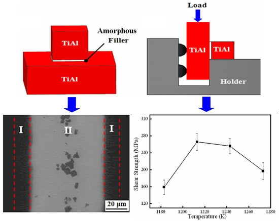
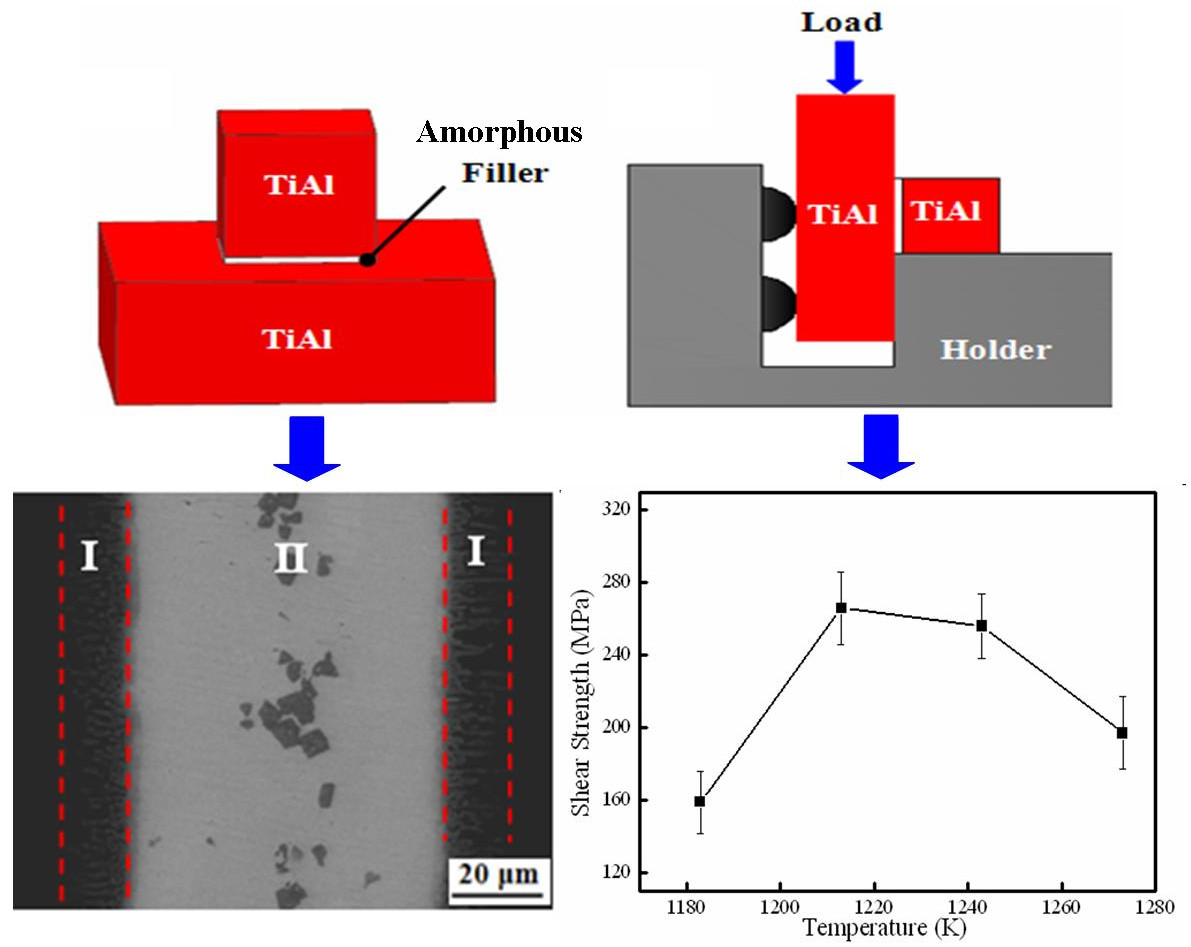
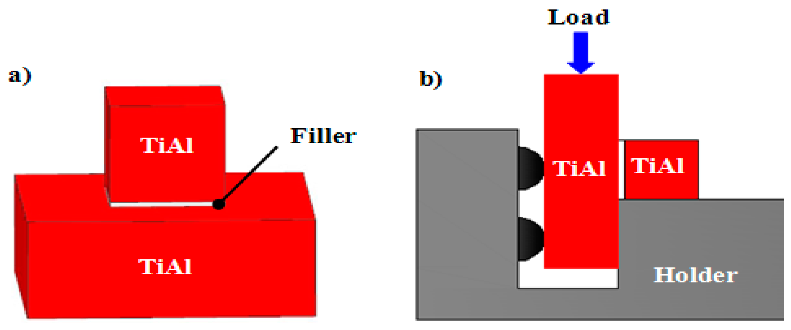
The size of the TiAl sample for brazing was 4 mm × 4 mm × 4 mm and 10 mm × 10 mm × 4 mm. Before joining, the surfaces of the samples were ground by 1000 grit silicon carbide paper and cleaned ultrasonically for 600 s. The Cu-based filler was placed between the Ti-48Al-2Nb-2Cr base materials to form a sandwich type, as shown in Figure 1a. The brazing experiments were done by JVLF211 vacuum brazing equipment. The accuracy of temperature controlling was ±1 K. The brazing temperature was from 1183 K to 1273 K, and the brazing time was set as 600 s. The brazing process was conducted in a vacuum of 1 × 10⁻³ Pa. At the beginning, the brazing sample was heated up to 573 K at a rate of 0.167 K/s and held steady for 1200 s to make the organic glue volatilize and keep the brazing surfaces clean. Then, the temperature was increased to the target brazing temperature at a heating rate of 0.167 K/s, and kept constant for 600 s. Finally, the brazed samples were cooled down at a rate of 0.083 K/s to 573 K, and then cooled in the furnace.
After joining, the microstructure and composition of the joints were examined by scanning electron microscopy (SEM, SU8010, Hitachi, Tokyo, Japan) with an energy-dispersive X-ray spectrometer (EDS) and X-ray diffraction. The structural analysis of the fractured surface of the joint was tested by XRD. Shear testing was performed by a universal testing machine Instron 5500 to evaluate the strength of the brazed joint. A schematic diagram of the shear test is shown in Figure 1b. The average shear strength of each brazing condition was determined from three brazed samples.
3. Results and Discussion
3.1. Microstructure of Ti-48Al-2Nb-2Cr Alloy
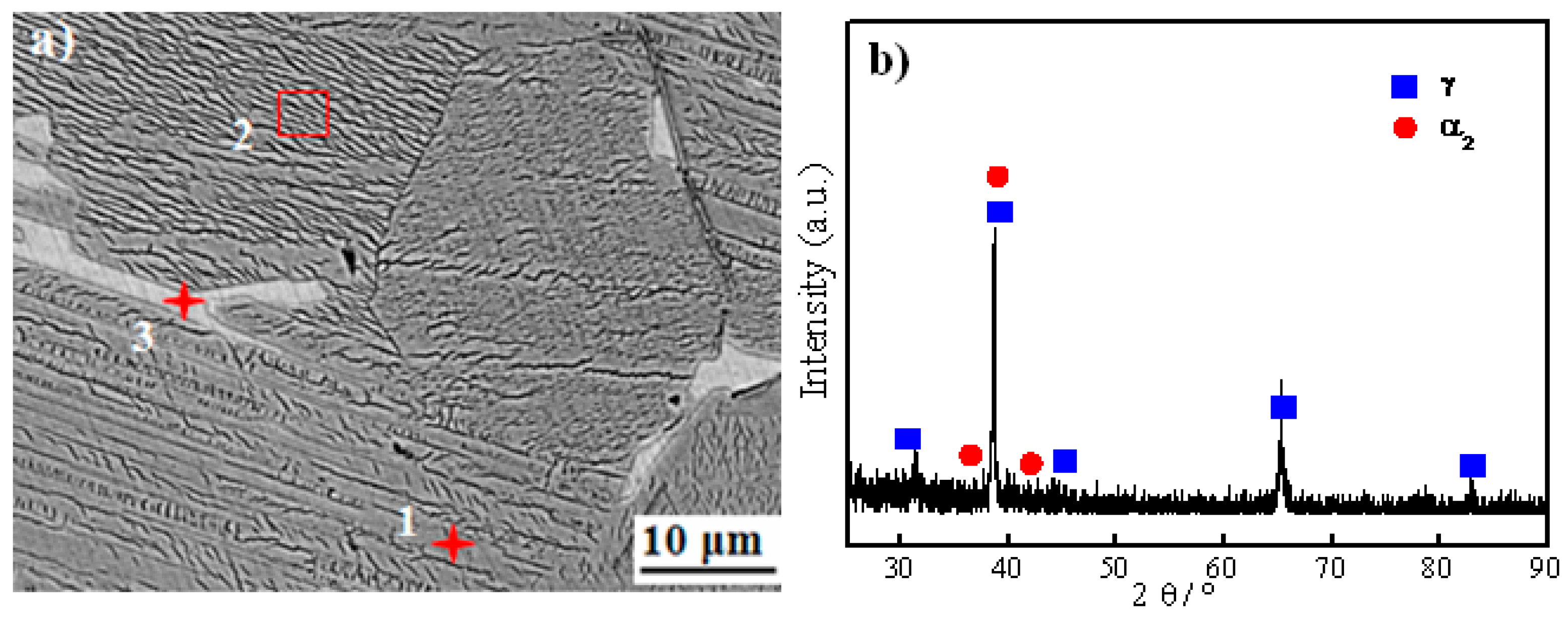
Figure 2 shows the SEM image and XRD pattern of the as-cast Ti-48Al-2Nb-2Cr alloy. The Ti-48Al-2Nb-2Cr alloy primarily consists of a lamellar structure, gray phases, and a few white phases. The chemical composition of the typical phases of the as-cast Ti-48Al-2Nb-2Cr alloy is listed in Table 1. According to the EDS and XRD results, gray areas are identified as the γ phase due to high Al content. The lamellar structure is α2 + γ phase. During the cooling process, the liquid through peritectic reaction L + β → α has transformed to the α phase incompletely, so that the retained β phase exists in a lamellar microstructure [28]. The white phases are rich in Cr and poor in Al, as shown in Table 1. Thus, the white phase should be the B2 phase produced by the transformation of the retained β phase. The similar results of the TiAl alloy have been demonstrated in the previous work [29,30].
3.2. Interfical Microstructure of the Brazed Joint
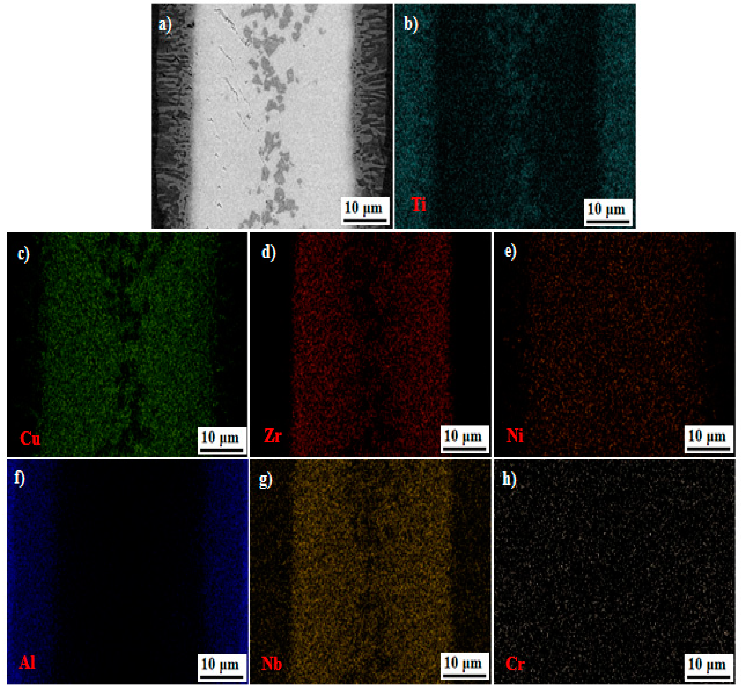
Figure 3 shows the interfacial microstructures and corresponding EDS results for the joint brazed at 1213 K for 600 s. Clearly, the TiAl substrates are tightly bonded by the Cu-based amorphous filler. No cracks or pores are found in the joint. Obvious reaction layers are detected in the interface, as shown in Figure 3a, which can be attributed to the interdiffusion and nucleation of new phases at the brazing temperature or during cooling. From Figure 3b–e, the main elements of Ti, Cu, Zr, and Ni are widely distributed in the whole joint. Moreover, Ti is aggregated on the location of the blocky black phase with the absence of Cu and Zr. It can be seen that the Al mainly distributes in the Ti-48Al-2Nb-2Cr side of the seam, as shown in Figure 3f. From Figure 3g,h, the existence of Nb and Cr in the brazing beam is attributed to the dissolution and diffusion of elements from the Ti-48Al-2Nb-2Cr alloy into the filler metal during brazing.
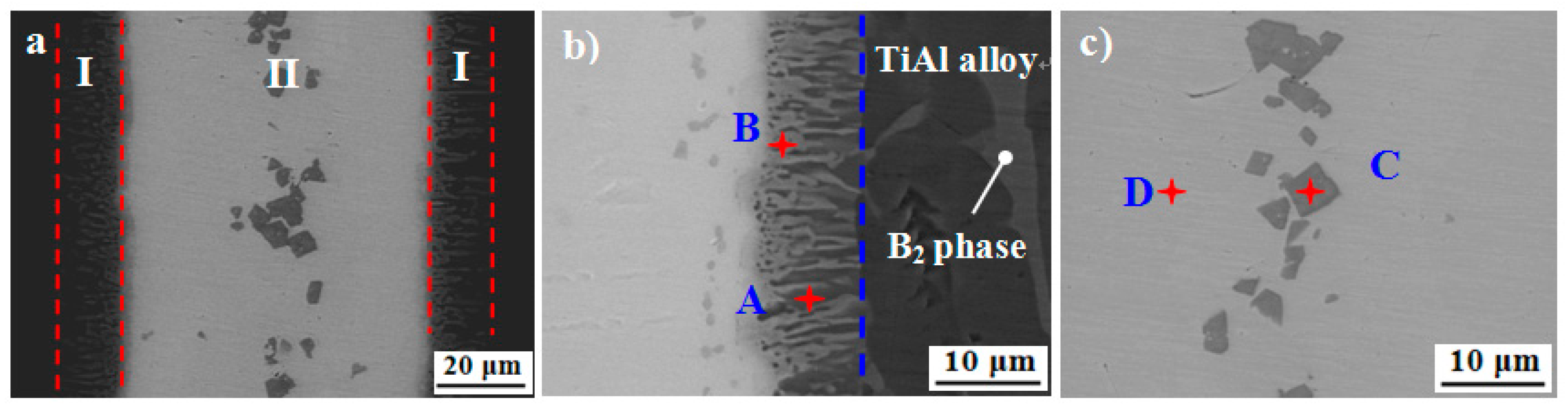
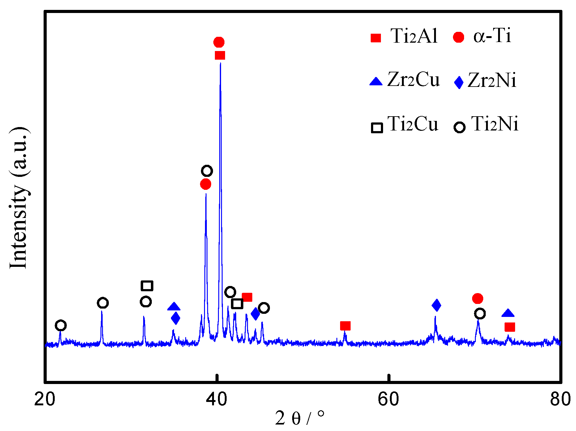
Figure 4a shows detailed microstructures of the brazed joint at 1123 K for 600 s. The width of the brazed joint is about 90 μm, which is thicker than the amorphous filler. Two kinds of reaction zones were identified in the brazed joint, which are marked as zone I and II, respectively. Figure 4b,c demonstrates the high magnification images of these two characteristic zones. Based on the contrast differences, zone I mainly consists of two phases marked by A and B. Some B2 phase can be observed in the TiAl alloy side. Similarly, zone II is also a two-phase mixed region, as marked by C and D. Table 1 lists the chemical composition of the brazed joints through EDS. From Figure 4b, a lamellar structure approximately 10-μm thick composed of alternate black and grey strips are detected in the brazed joint adjacent to the TiAl base material. According to the EDS results, the black phase (spot A) is mainly composed of Ti and Al at an approximate ratio of 2:1 with few Zr, Cu, Ni, Nb, and Cr. Based on the composition of the selected spots (marked as A–D in Figure 4b,c) and previous studies [31], spot A is inferred as the Ti2Al. It is reported that Ti2Al was an intermediate phase during the phase transformation between the Ti3Al and TiAl phases, and it was hexagonal with lattice parameters a = 0.29 nm and c = 1.39 nm [32,33]. Furthermore, Xiong et al. demonstrated that there was a reaction of Ti + TiAl → Ti2Al during hot press sintering [34]. Similarly, the gray phase (spot B) is mainly composed of Al, Cu, and Ti at a ratio of 1:1:1. Based on the composition, spot B is inferred to be AlCuTi. As Shiue reported, this kind of intermetallic was common in the reactions between TiAl alloy, Cu, and Ni in the brazing process [35]. According to the Al-Cu-Ti ternary alloy phase diagram [14], AlCuTi and TiAl share a boundary curve, indicating that AlCuTi is likely to be directly adjacent to the TiAl phase of the base material, which is consistent with our experimental observation, as shown in Figure 4b. Thus, spot B is identified as AlCuTi corresponding to the Al-Cu-Ti ternary alloy phase diagram. Also, the formation of a AlCuTi intermetallic compound in brazed joints has been reported in previous works. Liu et al. reported the presence of a AlCuTi phase in transparent alumina ceramic and TiAl alloy with AgCuTi filler metal [14]. Shiue et al. observed the obvious AlCuTi layer through SEM at the interface between BAg-8 and TiAl substrate for the specimen brazed at 1223 K [34]. Spot C in Figure 4c was mainly composed of 76.94 at. % Ti and 6.83 at. % Al. It has been reported that Al is α-Ti stabilizer, while Cu and Ni are β-Ti stabilizer elements [36]. Therefore, spot C was inferred to be α-Ti. Spot D in zone II was mainly composed of Zr, Ti, Cu, and Ni. The atom ratio of Cu + Ni and Ti + Zr was approximately 1:2. Compared with the original contents of Cu in an amorphous alloy, the decrease of Cu contents mainly caused by the consumption of copper from molten braze during brazing results in the formation of AlCuTi, as aforementioned. Both Cu and Ni are completely miscible with each other, as well as Ti and Zr. Cu and Ni have a strong affinity to Ti (Zr), and they are apt to form (Ti,Zr)2(Cu,Ni). In fact, both element pairs of Ti and Zr, and Cu and Ni, are not only chemically compatible with each other, they are also fully soluble to each other. Therefore, Zr and Ni can be regarded namely as Ti and Cu in the intermetallics herein. Thus, the Zr2Cu and Zr2Ni can be regarded as Ti2Cu and Ti2Ni. Therefore, the four phases can be collectively referred to as (Ti, Zr)2(Cu, Ni). So, spot D can be considered as having a phase formula of (Ti, Zr)2(Cu, Ni). The formation of (Ti, Zr)2(Cu, Ni) phase was also demonstrated in the previous work when amorphous filler metal was used [37,38]. Figure 5 shows the XRD patterns of the fractured surface of the sample brazed at 1213 K for 600 s. However, AlCuTi has not been detected by XRD due to the amount being too small for detection by the equipment. Based on the micro-XRD results, the chemical composition in Table 2, and the phase diagrams, phases A, B, C, and D can be recognized as Ti2Al, AlCuTi, α-Ti, and (Ti, Zr)2(Cu, Ni).
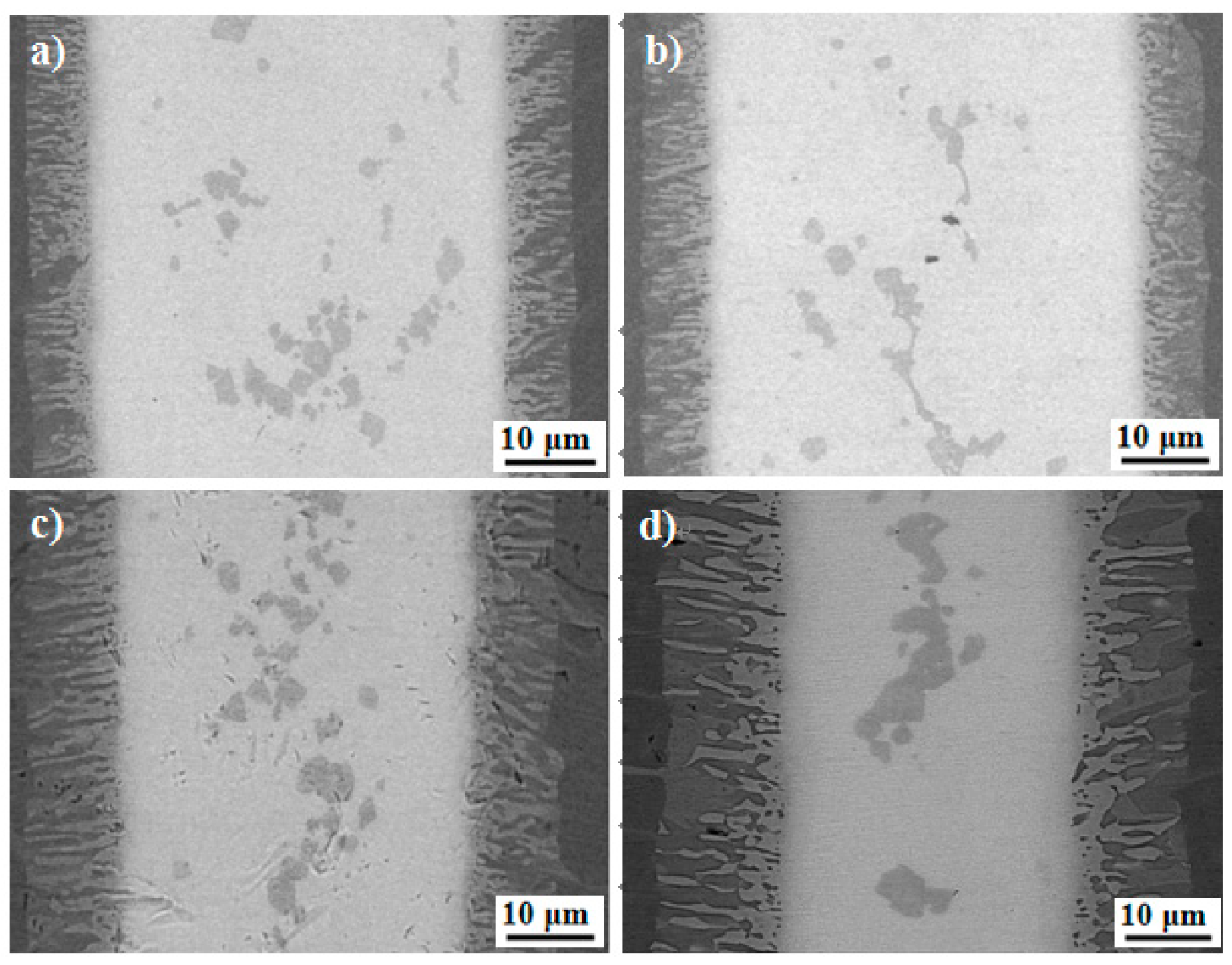
Figure 6 shows the SEM images of the brazed joint at different brazing temperatures for 600 s. Obviously, two characteristic zones can be seen in all of the brazed joints, and a continuous lamellar interface reaction layers forms in the interface, which is the same as in Figure 4a. The width of the whole joint remains unchanged with the brazing temperature. However, the width of the interfacial reaction layer zone I increased with the brazing temperature. Correspondingly, the width of the central brazed layer zone II decreased. For 1123 K, the width of interfacial reaction layer was about 5 μm. When the brazing temperature reached 1273 K, the width of the interfacial reaction layer increased to 15 μm. Also, the amount of the black phase in the interfacial reaction layer defined as the Ti2Al phase increased. However, compared with the Ti2Al phase, the amount of gray phase AlCuTi decreased in the interfacial reaction layer. It is reported that once the continuous TiAl intermetallic compounds form in the joint interface, further atomic interdiffusion between the base material and filler metal will be obstructed due to the limited solubility of Cu and Ni in the TiAl alloy [39]. Hence, the existence of Ti2Al obstructs the growth of AlCuTi in the interfacial reaction layer. The block-like α-Ti grows and accumulates with increasing brazing temperature.
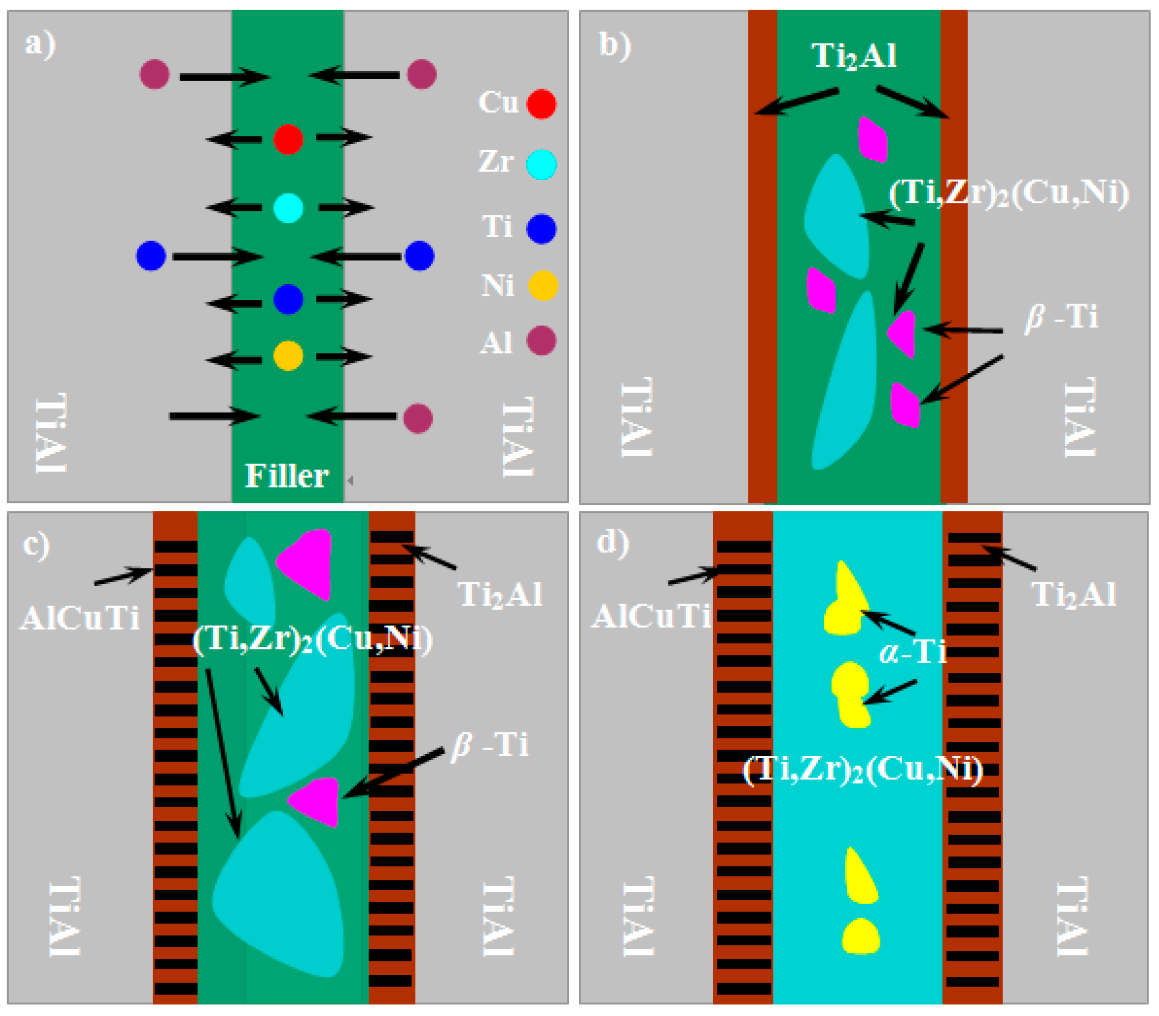
From the above experimental results, we propose a possible formation model to explain the microstructure evolution of the joint, as shown in Figure 7. During brazing, when the temperature was brought to the melting point of a Cu-based amorphous alloy filler, the filler began to melt, and wetted the surface of Ti-48Al-2Nb-2Cr base materials. The base materials were partially dissolved into the molten alloy. The Ti and Al diffused into the molten filler due to the concentration gradient. At the same time, the elements in the molten filler, especially the Cu, diffused into the Ti-48Al-2Nb-2Cr base materials, as shown in Figure 7a. During the heat process, the Ti and Al contents of the γ-TiAl and α2-Ti3Al phases in the Ti-48Al-2Nb-2Cr base materials gradually decreased, and eventually fell below the critical composition required for their existence [40]. As a consequence, the γ-TiAl and α2-Ti3Al phases transformed into the Ti2Al phase through chemical reactions of TiAl → Al + Ti2Al and Ti3Al → Ti + Ti2Al, respectively. Meanwhile, an eutectic reaction occurred based on Cu-Ni-Ti (Zr) ternary phase diagram L → β-Ti + (Ti,Zr)2(Cu, Ni), as shown in Figure 7b. With the further interdiffusion at the interface, the AlCuTi phase appeared according to the Al-Cu-Ti ternary alloy phase diagram. When the brazing temperature was further increased, the thickness of the interfacial reaction layers containing AlCuTi and Ti2Al increased. In addition, the (Ti,Zr)2(Cu, Ni) phase grew and aggregated, as shown in Figure 7c. At the cooling stage, when the brazing temperature is lower than the β → α transformation temperature, the eutectoid decomposition of β-Ti to α-Ti and (Ti, Zr)2(Cu, Ni) phases happens: β-Ti → α-Ti + (Ti, Zr)2(Cu, Ni). Therefore, the central reaction layer was finally formed with α-Ti and (Ti, Zr)2(Cu, Ni), as shown in Figure 7d.
3.3. Mechanical Properties of the Brazed Joint
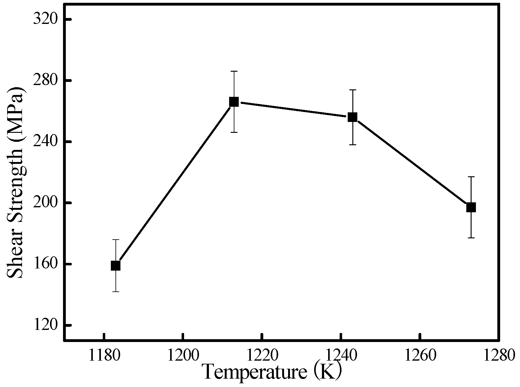
Figure 8 shows the room temperature shear strength of the joints brazed at different temperatures for 600 s. It can be seen that the shear strength of the joint is not satisfactory at low brazing temperatures. When brazed at 1183 K, the shear strength is very low: about 160 MPa. The main cause is the low amount of atomic diffusion and the insufficient dissolution reaction between the TiAl base alloy and the molten Cu-based filler metal. With the increasing brazing temperature, the joint strength changed correspondingly. When the brazing temperature is up to 1213 K, the maximum strength achieved 266 MPa. Two aspects could contribute to the maximum shear strength. Firstly, the increased brazing temperature can improve dissolution and diffusion, leading to the formation of the appropriate interfacial reaction layers in the interface [23,41]. In the present work, the brazing temperature changes the thickness of the reaction layers, as shown in Figure 6, and thus affects the joint strength directly. At the lower brazing temperature, the main cause was the low amount of atomic diffusion and the insufficient dissolution reaction between the TiAl base alloy and the molten Cu-based filler metal, which resulted in lower joint strength. Contrarily, the higher brazing temperature promoted the growth of reaction layers. It is reported that the thickness of the reaction layer dramatically influences the strength of the joint, and there is an optimized thickness of the reaction layers for brazed joints [42]. So, the strength of the reaction layers could be weakened when its thickness exceeds the best value. Secondly, a certain amount of AlCuTi phase homogeneously distributed in the interface, which made the reaction layers a metal matrix reinforced by AlCuTi particles. Further increasing the brazing temperature led to a dramatic deterioration of its bonding strength, and the shear strength was decreased to 197 MPa at 1273 K for 600 s. It is suggests that residual stresses might be yielded in the brazed joint due to the mismatch of the thermal expansion coefficient and Young’s modulus between the TiAl base material and the filler metal during the cooling process. These residual stresses can induce microcracks in the interface and deteriorate the mechanical properties [43]. Moreover, further increasing the brazing temperature leads to a larger amount and size of brittle intermetallics (e.g., Ti2Al and AlCuTi) at the interface, as shown in Figure 6. The existence of these intermetallics weakens the plastic deformation of the joint, which is detrimental to the relaxation of the residual stress in the joint. This consequentially leads to the decrease of shear strength.
4. Conclusions
The Ti-48Al-2Nb-2Cr alloy has been successfully joined to itself using Cu41.83Ti30.21Zr19.76Ni8.19 (at. %) amorphous alloy filler. Sound joints can be obtained for 10 min with different temperatures. The typical brazed joint consists of two zones: the interfacial reaction layer and the central reaction layer. The reaction products of Ti2Al, AlCuTi, α-Ti, and (Ti,Zr)2(Cu,Ni) were identified in the brazed joint. The size and morphology of the two zones, especially the phase in the interfacial reaction layer, are highly affected by the brazing temperature. It was found that the shear strength changes with the brazing temperature. An optimum shear strength of 266 MPa is achieved under the conditions of 1213 K for 600 s. The successful preparation of high strength Ti-48Al-2Nb-2Cr alloy joints, as well as the proposed formation mechanism, offers a promising brazing route for the fabrication and functionalization of other TiAl intermetallics.
Author Contributions
P.W., W.W. and D.Z. conceived and designed the experiments. G.W., X.S. and W.C. wrote the article. C.T. and Y.S. gave the suggestion of experiments, and provided the materials.
Acknowledgments
This work was supported by the National Natural Science Foundation of China [grant numbers 51704001 and 51501100], Key Project of Natural Science of Education Department of Anhui Province [grant numbers KJ2018A0860 and KJ2016A060], Talent Project of Anhui Province [grant number gxyqZD2016126] and the Open Fund of State Key Laboratory of Advanced Welding and Joining [grant number AWJ-16-M04]. W. Cao acknowledges financial supports from the profile funding of the Academy of Finland.
Conflicts of Interest
The authors declare no conflict of interest.
References
- Dimiduk, D.M. Gamma titanium aluminide alloys—An assessment within the competition of aerospace structural materials. Mater. Sci. Eng. A 1999, 263, 281–288. [Google Scholar] [CrossRef]
- Wu, X.H. Review of alloy and process development of TiAl alloys. Intermetallics 2006, 14, 1114–1122. [Google Scholar] [CrossRef]
- Zghal, S.; Thomas, M.; Naka, S.; Finel, A.; Couret, A. Phase transformations in TiAl based alloys. Acta Mater. 2005, 53, 2653–2664. [Google Scholar] [CrossRef]
- Garip, Y.; Ozdemir, O. Hot corrosion behavior of Ti-48Al and Ti-48Al-2Cr intermetallic alloys produced by electric current activated sintering. Metall. Mater. Trans. A 2018, 49, 2455–2462. [Google Scholar] [CrossRef]
- Liu, Y.Y.; Yao, Z.K.; Guo, H.Z.; Yang, H.H. Microstructure and property of the Ti–24Al–15Nb–1.5Mo/TC11 joint welded by electron beam welding. Int. J. Miner. Metall. Mater. 2009, 16, 568–575. [Google Scholar] [CrossRef]
- Basile, G.; Baudana, G.; Marchese, G.; Lorusso, M.; Lombardi, M.; Ugues, D.; Fino, P.; Biamino, S. Characterization of an additive manufactured TiAl alloy-steel joint produced by electron beam welding. Materials 2018, 11, E149. [Google Scholar] [CrossRef] [PubMed]
- Lei, Z.L.; Dong, Z.J.; Chen, Y.B.; Huang, L.; Zhu, R.C. Microstructure and mechanical properties of laser welded Ti–22Al–27Nb/TC4 dissimilar alloys. Mater. Sci. Eng. A 2013, 559, 909–916. [Google Scholar] [CrossRef]
- Du, Z.H.; Zhang, K.F.; Lu, Z.; Jiang, S.S. Microstructure and mechanical properties of vacuum diffusion bonding joints for γ-TiAl based alloy. Vacuum 2018, 150, 96–104. [Google Scholar] [CrossRef]
- Simões, S.; Viana, F.; Kocak, M.; Ramos, A.S.; Vieira, M.T.; Vieira, M.F. Diffusion bonding of TiAl using reactive Ni/Al nanolayers and Ti and Ni foils. Mater. Chem. Phys. 2011, 128, 202–207. [Google Scholar] [CrossRef]
- Simoes, S.; Ramos, A.S.; Viana, F.; Vieira, M.T.; Vieira, M.F. Joining of TiAl to steel by diffusion bonding with Ni/Ti reactive multilayers. Metals 2016, 6, 96. [Google Scholar] [CrossRef]
- Lee, S.J.; Wu, S.K. Infrared joining strength and interfacial microstructures of Ti-48Al-2Nb-2Cr intermetallics using Ti-15Cu-15Ni foil. Intermetallics 1999, 7, 11–21. [Google Scholar] [CrossRef]
- Wang, Y.; Cai, X.Q.; Yang, Z.W.; Qiu, Q.W.; Wang, D.P.; Liu, Y.C. Microstructure evolution and mechanical properties of Ti–22Al–25Nb alloy joints brazed with Ti–Ni–Nb alloy. Mater. Chem. Phys. 2016, 182, 488–497. [Google Scholar] [CrossRef]
- Shiue, R.K.; Wu, S.K.; Chen, Y.T.; Shiue, C.Y. Infrared brazing of Ti50Al50 and Ti-6Al-4V using two Ti-based filler metals. Intermetallics 2008, 16, 1083–1089. [Google Scholar] [CrossRef]
- Liu, X.P.; Zhang, L.X.; Sun, Z.; Feng, J.C. Microstructure and mechanical properties of transparent alumina and TiAl alloy joints brazed using Ag-Cu-Ti filler metal. Vacuum 2018, 151, 80–89. [Google Scholar] [CrossRef]
- Dai, X.Y.; Cao, J.; Liu, J.K.; Su, S.; Feng, J.C. Effect of holding time on microstructure and mechanical properties of ZrO2/TiAl joints brazed by Ag–Cu filler metal. Mater. Des. 2015, 87, 53–59. [Google Scholar] [CrossRef]
- Shiuea, R.K.; Wu, S.K.; Chen, S.Y. Infrared brazing of TiAl using Al-based braze alloys. Intermetallics 2003, 11, 661–671. [Google Scholar] [CrossRef]
- Song, X.G.; Ben, B.Y.; Hu, S.P.; Feng, J.C.; Tang, D.Y. Vacuum brazing high Nb-containing TiAl alloy to Ti60 alloy using Ti-28Ni eutectic brazing alloy. J. Alloys Compd. 2017, 692, 485–491. [Google Scholar] [CrossRef]
- Cao, J.; Dai, X.Y.; Liu, J.Q.; Si, X.Q.; Feng, J.C. Relationship between microstructure and mechanical properties of TiAl/Ti2AlNb joint brazed using Ti-27Co eutectic filler metal. Mater. Des. 2017, 121, 176–184. [Google Scholar] [CrossRef]
- Song, X.G.; Cao, J.; Chen, H.Y.; Wang, Y.F.; Feng, J.C. Brazing TiAl intermetallics using TiNi–V eutectic brazing alloy. Mater. Sci. Eng. A 2012, 551, 133–139. [Google Scholar] [CrossRef]
- Wang, G.; Xiao, P.; Huang, Z.J.; He, R.J. Brazing of ZrB2–SiC ceramic with amorphous CuTiNiZr filler. Ceram. Int. 2016, 42, 5130–5135. [Google Scholar] [CrossRef]
- Liu, Y.H.; Hu, J.D.; Shen, P.; Han, X.H.; Li, J.C. Microstructural and mechanical properties of jointed ZrO2/Ti-6Al-4V alloy using Ti33Zr17Cu50 amorphous brazing filler. Mater. Des. 2013, 47, 281–286. [Google Scholar] [CrossRef]
- Lee, M.K.; Lee, J.G. Mechanical and corrosion properties of Ti-6Al-4V alloy joints brazed with a low-melting-point 62.7Zr-11.0Ti-13.2Cu-9.8Ni-3.3Be amorphous filler metal. Mater. Charact. 2013, 81, 19–27. [Google Scholar] [CrossRef]
- Li, X.Q.; Li, L.; Hu, K.; Qu, S.G. Vacuum brazing of TiAl-based intermetallics with Ti-Zr-Cu-Ni-Co amorphous alloy as filler metal. Intermetallics 2015, 57, 7–16. [Google Scholar] [CrossRef]
- Wang, Y.; Jiao, M.; Yang, Z.W.; Wang, D.P.; Liu, Y.C. Vacuum brazing of Ti2AlNb and TC4 alloys using Ti–Zr–Cu–Ni and Ti–Zr–Cu–Ni + Mo filler metals: Microstructural evolution and mechanical properties. Arch. Civ. Mech. Eng. 2018, 18, 546–556. [Google Scholar] [CrossRef]
- Cai, Y.S.; Liu, R.C.; Zhu, Z.W.; Cui, Y.Y.; Yang, R. Effect of brazing temperature and brazing time on the microstructure and tensile strength of TiAl-based alloy joints with Ti-Zr-Cu-Ni amorphous alloy as filler metal. Intermetallics 2017, 91, 35–44. [Google Scholar] [CrossRef]
- Lu, Z.P.; Shen, J.; Xing, D.W.; Sun, J.F.; Liu, C.T. Binary eutectic clusters and glass formation in ideal glass-forming liquids. Appl. Phys. Lett. 2006, 89, 071910. [Google Scholar] [CrossRef]
- Liu, Y.P.; Wang, G.; Cao, W.; Xu, H.T.; Huang, Z.J.; Zhu, D.D.; Tan, C.W. Brazing ZrB2-SiC ceramics to Ti6Al4V alloy with TiCu-based amorphous filler. J. Manuf. Process. 2017, 30, 516–522. [Google Scholar] [CrossRef]
- Liu, Y.; Hu, R.; Zhang, T.B.; Kou, H.C.; Wang, J.; Yang, G.; Li, J.S. Dendritic growth and microstructure evolution with different cooling rates in Ti48Al2Cr2Nb alloy. J. Mater. Eng. Perform. 2016, 25, 38–45. [Google Scholar] [CrossRef]
- Liu, Y.; Hu, R.; Kou, H.C.; Zhang, T.B.; Wang, J.; Li, J.S. A mixture of massive and feathery microstructures of Ti48Al2Cr2Nb alloy by high undercooled solidification. Mater. Charact. 2015, 100, 104–107. [Google Scholar] [CrossRef]
- Niu, H.Z.; Chen, Y.Y.; Xiao, S.L.; Xu, L.J. Microstructure evolution and mechanical properties of a novel beta g-TiAl alloy. Intermetallics 2012, 31, 225–231. [Google Scholar] [CrossRef]
- Ren, H.S.; Xiong, H.P.; Chen, B.; Pang, S.J.; Chen, B.Q.; Ye, L. Vacuum brazing of Ti3Al-based alloy to TiAl using TiZrCuNi(Co) fillers. J. Mater. Process. Technol. 2015, 224, 26–32. [Google Scholar] [CrossRef]
- Yang, S.J.; Nam, S.W. Investigation of α2/γ phase transformation mechanism under the interaction of dislocation with lamellar interface in primary creep of lamellar TiAl alloys. Mater. Sci. Eng. A 2002, 329–331, 898–905. [Google Scholar] [CrossRef]
- Cao, G.H.; Skrotzki, W.; Gemming, T. Transmission electron microscopy investigation of Ti2Al precipitation in titanium aluminides during high-strain torsion. J. Alloys Compd. 2006, 417, 169–172. [Google Scholar] [CrossRef]
- Xiong, H.P.; Shen, Q.; Li, J.G.; Zhang, L.M. Design and microstructures of Ti/TiAl/Al system functionally graded material. J. Mater. Sci. Lett. 2000, 19, 989–993. [Google Scholar] [CrossRef]
- Shiue, R.K.; Wu, S.K.; Chen, S.Y. Infrared brazing of TiAl intermetallic using BAg-8 braze alloy. Acta Mater. 2003, 51, 1991–2004. [Google Scholar] [CrossRef]
- Qiu, Q.W.; Wang, Y.; Yang, Z.W.; Hu, X.; Wang, D.P. Microstructure and mechanical properties of TiAl alloy joints vacuum brazed with Ti–Zr–Ni–Cu brazing powder without and with Mo additive. Mater. Des. 2016, 90, 650–659. [Google Scholar] [CrossRef]
- Li, L.; Li, X.Q.; Hu, K.; Qu, S.G.; Yang, C.; Li, Z.F. Effects of brazing temperature and testing temperature on the microstructure and shear strength of γ-TiAl joints. Mater. Sci. Eng. A 2015, 634, 91–98. [Google Scholar] [CrossRef]
- Lee, J.G.; Choi, Y.H.; Lee, J.K.; Lee, G.J.; Lee, M.K.; Rhee, C.K. Low-temperature brazing of titaniumby the application of a Zr–Ti–Ni–Cu–Be bulk metallic glass (BMG) alloyas a filler. Intermetallics 2010, 18, 70–73. [Google Scholar] [CrossRef]
- Shiue, R.K.; Wu, S.K.; Chen, Y.T. Strong bonding of infrared brazed α2-Ti3Al and Ti-6Al-4V using Ti-Cu-Ni fillers. Intermetallics 2010, 18, 107–114. [Google Scholar] [CrossRef]
- Herrmann, D.; Appel, F. Diffusion bonding of γ (TiAl) alloys: Influence of composition, microstructure, and mechanical properties. Metall. Mater. Trans. A 2009, 40, 1881–1902. [Google Scholar] [CrossRef]
- Hong, I.T.; Koo, C.H. Microstructural evolution and shear strength of brazing C103 and Ti-6Al-4V using Ti-20Cu-20Ni-20Zr (wt %) filler metal. Int. J. Refract. Met. Hard Mater. 2006, 24, 247–252. [Google Scholar] [CrossRef]
- Wang, G.; Huang, Y.J.; Wang, G.C.; Shen, J.; Chen, Z.H. Brazing of Ti2AlNb based alloy with amorphous Ti-Cu-Zr-Ni filler. J. Wuhan Univ. Technol. 2015, 30, 617–621. [Google Scholar] [CrossRef]
- Tian, X.Y.; Feng, J.C.; Shi, J.M.; Li, H.W.; Zhan, L.X. Brazing of ZrB2-SiC-C ceramic and GH99 superalloy to form reticular seam with low residual stress. Ceram. Int. 2015, 41, 145–153. [Google Scholar] [CrossRef]
Figure 1.
Schematic diagram of (a) assembling brazing and (b) shear test experiment.

Figure 2.
(a) Scanning electron microscopy (SEM) image and (b) X-ray diffraction (XRD) pattern of Ti-48Al-2Nb-2Cr base material.
Figure 2.
(a) Scanning electron microscopy (SEM) image and (b) X-ray diffraction (XRD) pattern of Ti-48Al-2Nb-2Cr base material.

Figure 3.
Interfacial microstructure and elemental distribution of Ti-48Al-2Nb-2Cr alloy joint brazed at 1213 K for 600 s. (a) SEM image and (b) Ti, (c) Cu, (d) Zr, (e) Ni, (f) Al, (g) Nb, (h) Cr.
Figure 3.
Interfacial microstructure and elemental distribution of Ti-48Al-2Nb-2Cr alloy joint brazed at 1213 K for 600 s. (a) SEM image and (b) Ti, (c) Cu, (d) Zr, (e) Ni, (f) Al, (g) Nb, (h) Cr.

Figure 4.
(a) SEM image of the joint interface brazed at 1213 K for 600 s; (b) magnification image of zone I; (c) magnification image of zone II.
Figure 4.
(a) SEM image of the joint interface brazed at 1213 K for 600 s; (b) magnification image of zone I; (c) magnification image of zone II.

Figure 5.
X-ray diffraction (XRD) pattern of fractured surface of brazed joint.

Figure 6.
Interfacial microstructures of the joints brazed for 600 s at brazing temperature of (a) 1183 K; (b) 1213 K; (c) 1243 K; and (d) 1273 K.
Figure 6.
Interfacial microstructures of the joints brazed for 600 s at brazing temperature of (a) 1183 K; (b) 1213 K; (c) 1243 K; and (d) 1273 K.

Figure 7.
Formation model of joint: (a) dissolution and diffusion of elements; (b) formation of reaction layers; (c) formation of AlCuTi and growth of reaction layers; and (d) formation of α-Ti.
Figure 7.
Formation model of joint: (a) dissolution and diffusion of elements; (b) formation of reaction layers; (c) formation of AlCuTi and growth of reaction layers; and (d) formation of α-Ti.

Figure 8.
Effect of brazing temperature on shear strength of the joints brazed at different temperature for 600 s.
Figure 8.
Effect of brazing temperature on shear strength of the joints brazed at different temperature for 600 s.


Table 1.
Chemical composition and possible phase of each spot marked in Figure 1 (at. %).
Table 1.
Chemical composition and possible phase of each spot marked in Figure 1 (at. %).
| Position | Ti | Al | Nb | Cr | Possible Phase |
|---|---|---|---|---|---|
| 1 | 49.96 | 44.83 | 1.70 | 3.52 | γ |
| 2 | 48.12 | 47.60 | 1.06 | 3.22 | γ + α2 |
| 3 | 54.11 | 33.09 | 1.21 | 11.59 | B2 |
Table 2.
Chemical composition and possible phase of each spot marked in Figure 3 (at. %).
Table 2.
Chemical composition and possible phase of each spot marked in Figure 3 (at. %).
| Spots | Ti | Al | Cu | Zr | Ni | Nb | Cr | Possible Phase |
|---|---|---|---|---|---|---|---|---|
| A | 60.05 | 31.21 | 0.50 | 0.44 | 0.03 | 1.51 | 3.27 | Ti2Al |
| B | 28.39 | 30.38 | 28.41 | 6.54 | 6.44 | 1.47 | 3.58 | AlTiCu |
| C | 76.94 | 6.83 | 5.00 | 5.11 | 3.49 | 0.56 | 3.08 | α-Ti |
| D | 40.03 | 15.90 | 24.06 | 14.41 | 4.59 | 1.63 | 4.49 | (Ti,Zr)2(Zr,Ni) |
© 2018 by the authors. Licensee MDPI, Basel, Switzerland. This article is an open access article distributed under the terms and conditions of the Creative Commons Attribution (CC BY) license (http://creativecommons.org/licenses/by/4.0/).
Share and Cite
MDPI and ACS Style
Wang, G.; Wu, P.; Wang, W.; Zhu, D.; Tan, C.; Su, Y.; Shi, X.; Cao, W. Brazing Ti-48Al-2Nb-2Cr Alloys with Cu-Based Amorphous Alloy Filler. Appl. Sci. 2018, 8, 920. https://doi.org/10.3390/app8060920
AMA Style
Wang G, Wu P, Wang W, Zhu D, Tan C, Su Y, Shi X, Cao W. Brazing Ti-48Al-2Nb-2Cr Alloys with Cu-Based Amorphous Alloy Filler. Applied Sciences. 2018; 8(6):920. https://doi.org/10.3390/app8060920
Chicago/Turabian StyleWang, Gang, Peng Wu, Wei Wang, Dongdong Zhu, Caiwang Tan, Yongsheng Su, Xinying Shi, and Wei Cao. 2018. "Brazing Ti-48Al-2Nb-2Cr Alloys with Cu-Based Amorphous Alloy Filler" Applied Sciences 8, no. 6: 920. https://doi.org/10.3390/app8060920
Note that from the first issue of 2016, this journal uses article numbers instead of page numbers. See further details here.