Hybrid Laminate for Haptic Input Device with Integrated Signal Processing
by
 , , ,
, , ,
René Schmidt
1,* ,
,
Alexander Graf
2,
Ricardo Decker
3,
Verena Kräusel
2,
Wolfram Hardt
1,
Dirk Landgrebe
2 and
Lothar Kroll
3 1
Computer Engineering, Chemnitz University of Technology, Straße der Nationen 62, 09111 Chemnitz, Germany
2
Forming and Joining, Chemnitz University of Technology, Reichenhainer Straße 70, 09107 Chemnitz, Germany
3
Department of Lightweight Structures and Polymer Technology, Chemnitz University of Technology, Reichenhainer Straße 31/33, 09126 Chemnitz, Germany
*
Author to whom correspondence should be addressed.
Appl. Sci. 2018, 8(8), 1261; https://doi.org/10.3390/app8081261
Submission received: 29 June 2018
/
Revised: 23 July 2018
/
Accepted: 26 July 2018
/
Published: 31 July 2018
(This article belongs to the Special Issue Smart Sustainable Manufacturing Systems)
Abstract
:Featured Application
haptic input device for car interior or structural health monitoring crash relevant components.
Abstract
Achieving lightweight construction through only material substitution does not realize the full potential of producing a lightweight material, hence, it is no longer sufficient. Weight-saving goals are best achieved through additional function integration. In order to implement this premise for mass production, a manufacturing process for joining and forming hybrid laminates using a new tool concept is presented. All materials used are widely producible and processable. The manufactured cover of an automotive center console serves to demonstrate a human interface device with impact detection and action execution. This is only possible through a machine learning system, which is implemented on a small—and thus space- and energy-saving—embedded system. The measurement results confirm the objective and show that localization was sufficiently accurate.
1. Introduction
Laminates made of different materials, such as plastic and metal, are referred to as hybrid laminates. The combination of metal sheets with fiber reinforced plastics (FRPs) results in completely new property profiles, which are characterized by low weight combined with high specific rigidity and strength. This enables high degrees of lightweight construction. The insertion of the metal layers significantly improves the damage tolerance of the FRP, making the hybrid laminates predestined for use in the aviation industry. A well-known representative is GLARE (Glass Laminate Aluminum Reinforced Epoxy), a glass fiber reinforced epoxy resin aluminum foil laminate, which is the result of further development of the oldest known hybrid laminate, ARALL (aramid fiber reinforced epoxy resin aluminum foil laminate). The layer structure of GLARE consists of glass fiber prepreg layers combined with aluminum sheets. However, due to the use of the thermoset matrix material, which has a long curing time, and the complex plant technology required, the production costs for these hybrid components increase [1]. The challenge to reduce these costs was met in a joint project at Chemnitz University of Technology, and hybrid laminates with a thermoplastic matrix were developed under the brand names CAPAAL© (carbon fiber reinforced polyamide aluminum laminate) and CAPET© (carbon fiber reinforced polyetheretherketone titanium laminate) [2].
Another approach to decreasing the weight is the integration of additional functions in structural components. Piezoceramic elements, for example, can be injection-molded with electrically conductive polymers and used, for example, for structural monitoring in fiber reinforced plastics [3]. Similarly, piezoceramic fibers—which are inserted into microcavities produced by forming, and joined by forming technology—enable the monitoring of metal components [4]. However, the efficient and large-scale production of hybrid laminates with large-area integration of sensors for detection and localization of impacts and deformations in hybrid sheet metal structural components is not yet available.
The forming of hybrid laminates presents a particular challenge in order to avoid failure of the individual layers due to tearing, delamination, and wrinkling. Successful forming can therefore only be achieved by adequate temperature control [5]. Harhash [6] goes on to discuss the effect of the core thickness on the mechanical properties. Furthermore, the failure during deep drawing is described, as is the beginning of crack propagation. Further research on the forming of hybrid laminate can be found in [7]. The laminate is preheated and then formed in a heated tool. The exact description of the material properties at elevated temperature, especially near the melting temperature, is a great challenge for the finite element (FE) simulation. A possible approach is the determination of these characteristic values by a representative volume element [8]. Nondestructive testing of hybrid laminates is also intended to detect defects that have a direct effect on the forming properties [9].
One field of application for hybrid laminates is represented by impact detection. In this field of application, three main algorithm approaches have emerged. The first class includes algorithms detecting impacts by precomputed reference values [10,11]. These algorithms face the drawback of low adaptability, since each component has to be measured individually. The second class represents signal-theoretical approaches for impact detection relying on direction of arrival estimation. Determination of the direction of arrival is based on cross-correlation [12], which is used for impact detection and localization on aircraft wings [13]. The third class covers localization with machine learning methods. For this purpose, various signal properties are extracted and used as inputs for various machine learning training techniques [14]. The main difference between the last two described classes are the good results from the signal processing class, as long as the objects are well shaped; if the objects are strongly deformed and no mathematical model can be found, machine learning approaches are preferred. The number of machine learning algorithms rises constantly and covers a wide range of research and application fields. Therefore, [15] used the support vector machine, while [16] relied on the kernel extreme learning machine. The most commonly used techniques are neural networks [17,18], whereby the quality of the procedure always depends on the features used to represent the selected signal property. Haywood et al. [19] and LeClerc et al. [20], for example, used features generated by Fourier and Hilbert transform, accompanied by high computational costs. In contrast, [12] focuses on features with low computational effort. The machine learning methods and signal properties to use cannot be generically determined and depend on the respective application.
The rest of this work is organized as follows. First, a novel manufacturing process for hybrid laminates with sensor functionality is described, addressing a continuous process chain and guaranteeing constant quality. Subsequently, a digital signal processing chain is described, demonstrating that the manufacturing process is accurate, does not damage sensor functionality, and has practicable usability. Finally, a conclusion about the presented results is drawn.
2. Manufacturing of Hybrid Laminates with Sensor Functionality
For manufacturing of hybrid laminates with sensor functionality [21], a large-scale process chain was developed. This innovative process chain combines the polymer processing technologies of compounding and foil extrusion with the rolling and forming of metal parts. In the first subprocess (Figure 1, label 1), the starting materials are blended into a piezoceramic thermoplastic compound and extruded as a thin foil, which forms the active component of the hybrid laminate. Therefore, the polypropylene homopolymer Moplen HP501H (LyondellBasell, Rotterdam, the Netherlands) is functionalized with piezoceramic lead zirconate titanate (PZT) powder NCE 55 (Noliac A/S, Kvistgaard, Denmark) and carbon nanotubes (CNTs) NC7000 (Nanocyl S.A., Sambreville, Belgium). The optimal material composition and processing properties were determined in previous investigations. Hence, the piezoceramic foil consisted of 70 wt % PZT and 0.5 wt % CNTs [22,23]. A foil thickness of 250 µm provides the optimal conditions for joining (Figure 1, label 2) the piezoceramic foil with aluminum sheets. The surface of the aluminum metal sheet (EN AW-6082 T4 with a thickness of 0.5 mm) was treated before joining. Grinding and additional etching with sodium hydroxide has proven to be a reliable method (acceptable adhesion when close to a large-scale reaction). After joining the piezoceramic foil and the copper sheets, cutting was carried out by water jet. A special tool concept was developed for the forming process, in which the composite is heated, formed, and cooled in the tool (Figure 1, label 3).
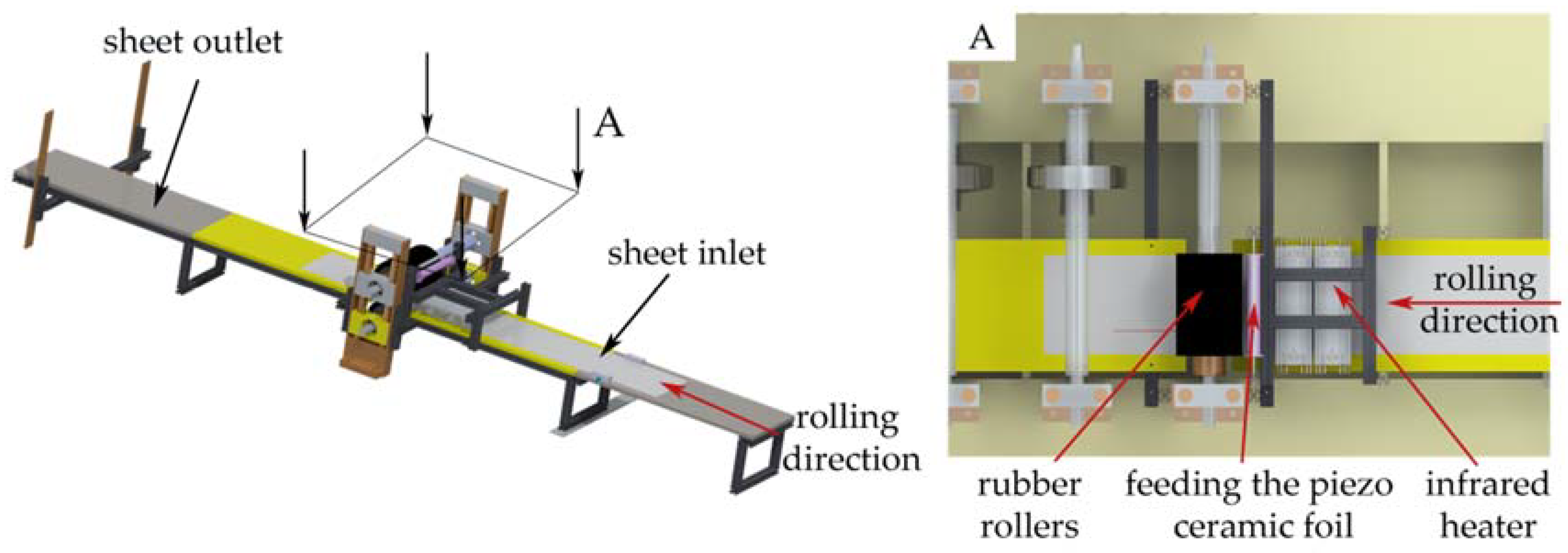
For continuous joining, the first tests were carried out on a pilot rolling mill [24]. After successful completion, a system was developed which allows a sample size with a width of up to 300 mm and a theoretically infinite length. The concept is shown in Figure 2. The system consists of a sheet metal inlet, which is also used for heating, and a sheet metal outlet, in which the finished composite cools down slowly. The actual joining process takes place directly after heating by infrared radiation (Figure 2, right A). After feeding the piezoceramic foil and (optionally) the copper strips, the composite is joined by the pressure of the rubber rollers. The thermoplastic melts in the contact area and forms a strong bond by adhesion. The process is monitored by thermocouples under the infrared radiators, and the temperature is measured by a pyrometer just before the rolls. The first tests showed that the parameters are not completely transferable from the pilot rolling mill. Due to the larger width of the sheets, the infrared emitters were arranged differently, thus causing better coupling and heating in the sheet. After a short parameter variation, it was possible to find the appropriate setting and produce hybrid laminates with sensor functionality.
The forming of the hybrid laminates was investigated in preliminary tests by V-bending and deep-drawing. The forming temperature, at which the brittle plastic does not tear or flow out, was particularly important. All the described preliminary work was carried out with a tool heated by heating cartridges and samples preheated in the furnace. The V-bending experiments showed that if the temperature is too low, the piezoceramic compound cracks. This is due to the fact that it is rather brittle due to the high proportion of ceramics. Only from a forming temperature of 100 °C did the piezoceramic compound not fail. With a further increase in temperature to 180 °C, the plastic flowed due to the reduction in viscosity. This was particularly evident at 180 °C, at which the piezoceramic compound was strongly thinned out and flowed laterally out of the sample (a more exact description is published in [24,25]). To further limit the forming temperature, DSC (differential scanning calorimetry) analysis of the piezoceramic compound was carried out. DSC confirmed the results of the preliminary tests: the melting starts at 110 °C and the maximum enthalpy of melting is reached at 167.8 °C, which also represents the melting point.
The findings were transferred to the manufacture of a cover for the center console of an automobile. With this part, it should be possible to carry out different actions in the car by localizing impacts. A new tool concept was developed for the forming process. Figure 3 shows the overall structure of a servo-electric press. Instead of heating cartridges, a variothermal heater was used, which uses water to heats the tool to 190 °C and cools it down to 20 °C again. This occurs by two separate circuits, which are connected by valves. Furthermore, an oven for preheating was omitted, and the heating was placed directly in the press by means of infrared radiators (Figure 3, right B). The procedure is as follows: The sample is inserted into the sample holder and preheated by means of infrared radiation. The specimen holder can be moved and is pushed on a guide to the tool. The free programming of the servo-electric press allows initial bending of the outer cover geometry when the tool is closed in a path-controlled manner, and then switches to a force-controlled control system in order to deep-draw the inner contour with the drawing cushion. Upon completion of the forming process, the hot forming tool is rapidly cooled by the variotherm unit. Thus, the plastic solidifies, and the component can be removed afterward.
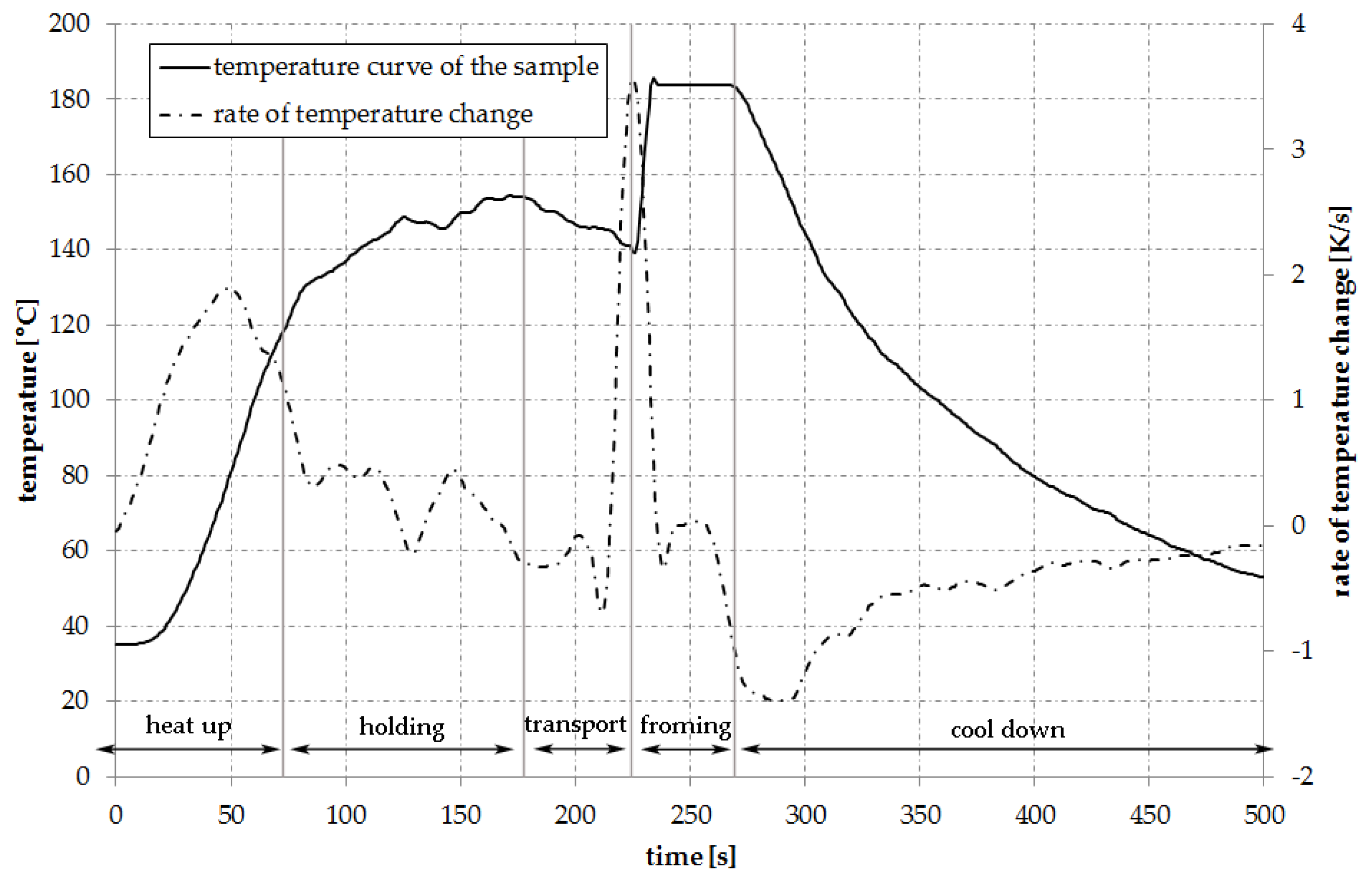
To adjust the process, a sample made only of aluminum was provided with thermocouples in order to record the working temperature (Figure 4). The rate of the temperature change was determined by the first derivative over time, which clearly showed the alternation of heating, holding, and cooling. The process steps described above are indicated in Figure 4.
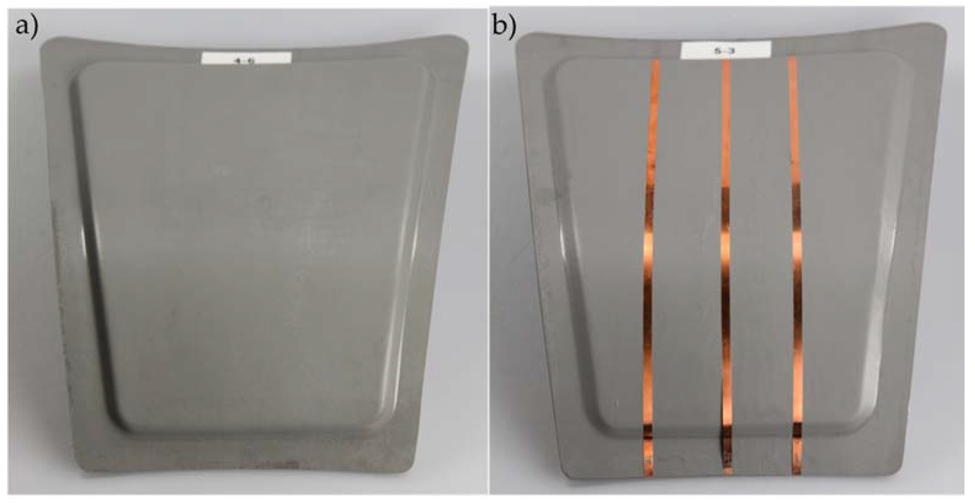
In the tests, the preheating temperature and the die temperature proved to be the most important parameters for defect-free forming. If these temperatures are set too low, tears and/or delamination occurs. Figure 5 shows the behavior if the temperature in the process is too high and the viscosity of the plastic is too low. It can be seen that the plastic flows out of the drawing gap, and thinning occurs in the middle. The parameters for the experiment were: preheating temperature infrared radiator 200 °C and tool temperature 170 °C. These parameters are identical to those from the test in Figure 4, and, when looking closely at the measured value, it can be determined that the temperature was above the melting temperature of the DSC analysis. After further tests, and by adjusting the parameters to the preheating temperature of the infrared radiator 180 °C and the tool temperature 150 °C, a component could be produced without thinning and melting, and without cracks. Two variants formed with these parameters are shown in Figure 6. The first variant is without copper strips (Figure 6a); it is mainly used for the individual application of electrodes. The second variant represents the complete mass production of a component with electrodes (Figure 6b). The results showed that the process is mastered and that, with the right parameters, a component can be produced without defects.
For activating the sensor effect of the hybrid laminate, a polarization process has to be conducted (Figure 1, label 4). Due to the extrusion, joining, and forming temperatures, which are higher than the Curie temperature of the PZT component, the piezoceramic particles depolarize during these processes. Therefore, the functionalized hybrid laminate must be polarized after the forming process. Based on previous experiments, the polarization process was conducted at elevated temperatures, between 100 °C and 120 °C [24]. In this temperature range, it is possible to polarize the piezoceramic layer during the cooling phase, after forming the hybrid part. By using this procedure, the residual heat of the forming process renders the reheating for polarization redundant. This approach has great potential for saving energy and resources, as well as for reducing cycle times during the fabrication process of multifunctional lightweight structures based on hybrid laminates.
In order to demonstrate real-world functionality, practical usability, and accuracy of the described manufacturing process, one center console, shown in Figure 6a, was equipped with four sensors to detect and localize the touch of a human finger. Therefore, the following section presents a novel measurement system architecture with integrated machine learning functionality.
3. Signal Processing
3.1. System Description
The sensor function of the hybrid laminate uses the piezoelectric effect. Mechanical loads on the multifunctional lightweight structure, e.g., impacts on the surface, induce displacements of the electrical dipoles within the piezoceramic particles. These displacements generate measurable electrical voltages between the copper electrodes and the aluminum sheet of the hybrid laminate, which can be further processed with the assistance of digital measuring methods. One possible application is represented by impact detection, which is used as an exemplary case for showing the functionality of the manufacturing process of the sensors, as well as the given practical usability. In our previous work, Ullmann et al. showed that, with the same sensors, a sufficiently high localization accuracy can be achieved on the basis of a Support Vector Machine (SVM) usage combined with time difference computation, although the test objects are mathematically difficult to describe [26]. However, for practical use, real-time functionality has to be ensured, just as energy efficiency must be confirmed. The previous solutions from [26] offer a solid basis for data collection and evaluation, but they are unsuitable for practical use. The main problem is represented by the used UART Interface, since the provided data rates are too small for the large amounts of data, leading to big buffers accompanied by high hardware requirements. The second main problem is that data processing on conventional PCs limits the practical use in cars or airplanes. For this reason, the process was transferred to an energy-efficient embedded system on chip (SoC) design, providing real-time capability, low power consumption, flexible application possibilities, and the accuracy necessary for real-world scenarios.
The basis for the design is a Zynq XC7Z010 SoC provided by Xillinx, representing a combination of FPGA and a Cortex A9 ARM processor connected by a standardized AXI interface, providing fast and highly flexible communication methods accompanied by high data throughput. The novel system architecture is depicted in Figure 7. As a test object, a center console with four sensors was used—three were placed in a vertical column and one was off-centered with a base distance of 5 cm. The object is stimulated by a light impact generated by contact from a human finger, leading to a visible voltage difference at the sensors. However, the sensor signals have a very low impedance, leading to insufficient measurement results by ADC usage. For data acquisition, the analog signals have to be stabilized energetically first. Afterwards, the signals must be transformed to the corresponding measuring range of the ADC. This task is performed by an electric circuit, which ensures the correct transformation of the analog signals to digital signals. The stabilized data are sampled and digitized using Xilinx’s integrated XADC. The configuration and data sampling are handled by the ADC interface depicted in Figure 7. In the following steps, the data are smoothed by a moving average filter, and the necessary features are extracted and implemented on the FPGA. The resulting features are transferred to the SVM classification process realized in software executed on the ARM processor. Due to embedded Linux usage on the processor part, all arbitrary communication interfaces, like Ethernet, CAN, or UART, can be used to send the localization results to the most common possible applications. In the following, the necessary steps for impact detection are explained in detail.
3.2. Electric Circuit
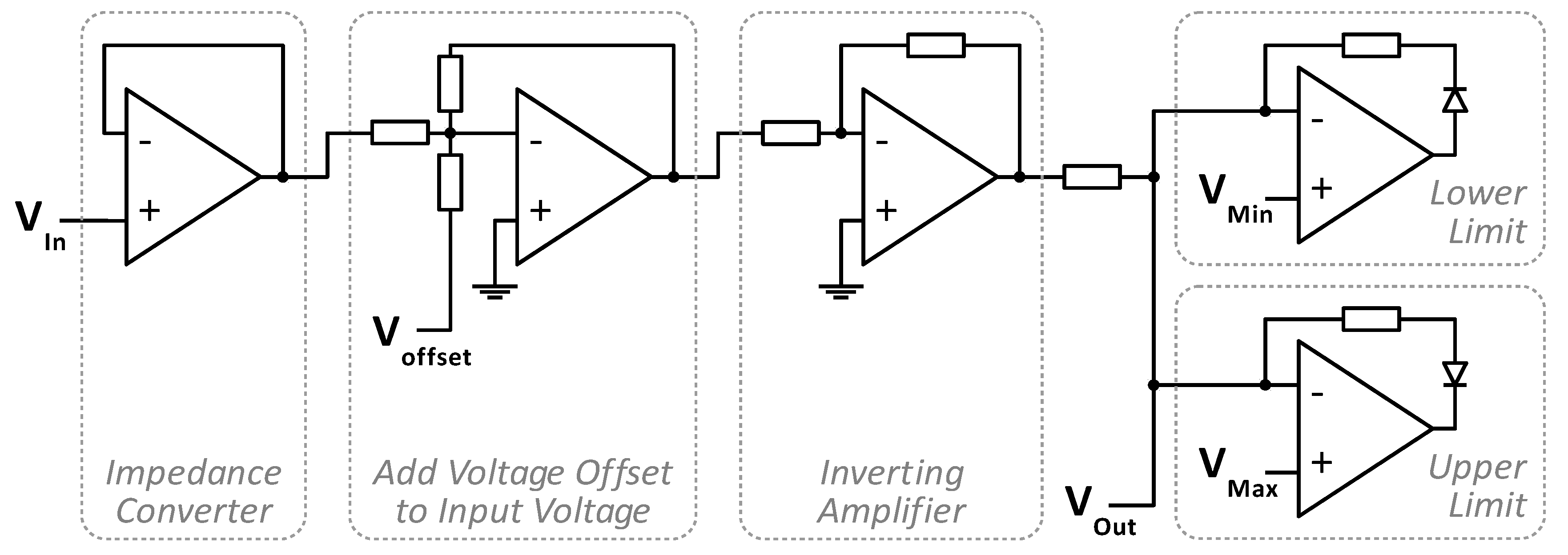
The sensor signal generation is based on the piezo effect, leading to an increasing voltage on the sensor output. However, the sensor has no external power supply, resulting in voltage changing without generating new current. Consequentially, the sensor signal has too low an impedance to be measured with common ADCs. Therefore, the low impedance signal must be transformed into a high impedance signal to ensure the correct ADC conversion; additionally, the value range of the ADC must be secured. For this reason, the first process step is an impedance converter, which infuses additional energy to the signal without changing the voltage characteristic (cp. Figure 8). The amplifier used should not influence the sensor signal frequency, and it should work with the onboard voltage as a power supply. In the following steps, the measuring range of the XADC, from 0 V to 1 V, is ensured. Therefore, the voltage has to be shifted to the positive voltage range by applying an offset of 0.5 V, leading to an inversion of the signal determined by the characteristics of the used operational amplifier (LM324N). For this reason, the subsequent step inverts the signal again. In the last step, the limitation of the measurement range must be secured. This is realized by two limiters cutting the signal at less than 0 V and higher than 1 V. As a result, the signal is converted from a low impedance signal with an arbitrary range to a signal with high impedance shifted by 0.5 V, limited to the ADC measurement range.
3.3. Signal Preprocessing
The preprocessing of the data starts with the data acquisition at the XADC, which converts the generated analog voltages of the electrical circuit into digital values, represented as the ADC interface in Figure 7. The XADC is a multichannel ADC with a theoretical maximum sampling rate of 1 MSps. Internally, the XADC consists of two synchronized ADCs with a sampling rate of 1 MSps and a configurable multiplexer used for switching the different measurement channels. For this reason, the number of used channels is not negligible, since it defines the final sample rate per measurement channel and can lead to wrong conversion results. In the described architecture, four channels are used, where two channels are mapped to ADC1 and the other two channels are mapped to ADC2, respectively, leading to a sample rate of 500 kSps on ADC1 and ADC2. To guarantee data consistency, ADC2 has been configured to work synchronously with ADC1, concluding in a final sample rate of 500 kSps, which defines the measurement window size and buffer sizes. Switching the channels and initial configuration of the XADC is guaranteed by the ADC interface.
A gradient-based algorithm is used as a feature extractor for the machine learning part (cp. Section 3.4.). The gradient calculation is sensitive to interferences, since a high-frequency noise signal is always accompanied by fast-changing amplitudes, leading to higher gradients. For this reason, the data are smoothed using a moving average filter. For this purpose, a shift register was implemented that satisfies the condition , with and shift register length , thus efficiently implementing the division by a power of 2. The division by a power of 2 can be implemented by a shifting operation of bits, represented as the SHR block in Figure 7. Since determining the sum for large measurement window sizes would require a lot of resources, the filter value was calculated according to formula:
The first part of the equation can be implemented efficiently by continuously accumulating the incoming samples. The second part represents the same summation, but the signal is shifted by samples in time. Therefore, the input signal is delayed for samples by the shifting register and is subtracted continuously. This offers the advantage of linear scalability, while the arithmetic operation is reduced to a summation and subtraction, leading to complexity reduction and avoiding timing problems.
3.4. Feature Extraction and Impact Localization
The feature extraction is based on the determination of the summed gradient, which is displayed in Figure 7 as the SG block. The first step of the feature extraction is the parallel transfer on each separated channel. The signal filtered during preprocessing serves as continuous input signal. The first processing step is the gradient calculation, represented as the ABS_DIFF block in Figure 7. The gradient is defined as the absolute difference between two consecutive samples. The implementation is carried out by following equation:
In the process, the gradients from a defined start time t = 0 are added up successively. The required start time is generated by a threshold comparison. For this purpose, the amplitude of the filtered signals on all measurement channels is compared to a parameterizable threshold value, generating the start signal for summation when all amplitudes exceed the defined threshold.
The result is the sum of the absolute gradients at a specific point in time per the measurement channel depicted in Figure 9. The generated data are passed to the subsequent function block TIME_DIFF_EXTR. This block determines the times of the gradients when they exceed a specified threshold value. For this purpose, a counter is used as a time reference, which is incremented with each incoming sample. To prevent overflows and the associated false measured values, the counter is in the reset state until the summation of the gradients begins. This creates a direct start condition and implicitly defines the start of the time measurement. The counter value is stored each time the threshold value is exceeded for the first time. If all channels fall below the threshold value, the measurement is considered complete. The resulting time difference representing the signal shift on the different measurement channels is sent to the processing system via AXI interface, proceeding to the SVM classification process.
In the software, machine learning occurs by an SVM. For this reason, an SVM was realized on the basis of LIBSVM [27], which provides a high-performance cross-platform solution. To generate the SVM model, 20 measuring points on the center console were defined in a grid pattern. Twenty-six measurements were carried out at each of these measuring points, resulting in 520 measurements, of which 400 were used for training and 120 were assigned as the test data set. For evaluation purposes, the described design was implemented with a window size of 64 samples, an amplitude threshold 2 times higher than the maximum amplitude in idle mode, and a threshold for gradient comparison of 40 V, as identified by heuristic evaluation. To evaluate the SVM kernel functions, the linear, the polynomial, the radial base, and the sigmoid kernel were trained with the described training data set resulting in individual models, which were applied to the test data set. The results of the training and test phases are depicted in Figure 10. It is shown that the radial basis kernel provides very good training results, whereas the test results are not sufficient, while the linear kernel and the polynomial kernel provide less accurate training results but provide sufficient results on the test data set. On the other hand, the sigmoid kernel provides insufficient results in testing and training.
4. Conclusions
A new hybrid laminate with sensor functionality was presented. It offers the possibility of combining lightweight construction and functional integration into a component, and producing it in large quantities. For this purpose, it was necessary to develop a continuous joining technology which combines continuous piezoceramic foil and an aluminum sheet, and it guarantees a constant quality. This was achieved through previous research and further investigation.
A new heating concept and a new tool concept using variothermal tempering were developed for further processing. Both have been integrated into a servo-electric press to minimize cycle time and energy loss caused by transport. By measuring the temperature on a sample plate, the process was verified. Good parts of high quality were produced with appropriate parameters.
In further investigations, the parts will be scanned by an optical measuring system and compared with the target geometry. The acquired information about thinning and springback will form the basis of adjusting the FE simulation and further improving the process. The polarization behavior of hybrid laminates with modified PZT components, as well as the development of tool concepts for in-line polarization processes, are still part of ongoing research activities.
In the signal processing part, an electrical circuit was implemented to amplify the low impedance piezoelectric effect signal and to ensure the correct measuring range. On the other hand, a full pipelined FPGA structure was presented, guaranteeing real-time processing. On the basis of the novel SoC architecture, the feature determined in the FPGA can be passed directly to the ARM processor, which classifies the features using an SVM, which had 94% accuracy on the training set and 84% on the testing set. With a power consumption of approximately 1.7 W, the presented solution is also very efficient in terms of energy consumption, enabling usage in mobile devices. However, although the used data set represents a valid basis for ensuring the evidence of feasibility, additional human-specific parameters, such as touch pressure, touch length, and characteristics of human fingers, have to be evaluated in further research before commercial use.
In summary, a novel manufacturing process for the production of piezo-based hybrid laminates was described. Further processing of the laminate—forming and in-line polarization—enable multifunctional structures, e. g., automotive center consoles with integrated touch functionality. The input gestures are processed by machine learning methods on an embedded system. The accuracy of the procedure was presented by an energy-efficient and real-time SoC solution, which precisely localized points of touch by human fingers. This demonstrates the practicability and usability of the hybrid laminates and the signal processing.
Author Contributions
Writing—aoriginal draft, R.S., A.G. and R.D.; Writing—review & editing, V.K., W.H., D.L. and L.K.
Funding
Deutsche Forschungsgemeinschaft: EXC 1075; Deutsche Forschungsgemeinschaft: GRK 1780/1; Deutsche Forschungsgemeinschaft: SFB/TR 39.
Acknowledgement
We gratefully acknowledge the cooperation of our project partners and the financial support of the DFG (Deutsche Forschungsgemeinschaft) within the Collaborative Research Center/Transregio 39 ‘‘PT-PIESA’’, the Federal Cluster of Excellence EXC 1075 ‘‘MERGE’’ and GRK 1780/1 CrossWorlds.
Conflicts of Interest
The authors declare no conflict of interest.
References
- Vlot, A.; Gunnink, J.W. Fibre Metal Laminates an Introduction; Kluwer Academic Publishers: Dordrecht, The Netherland, 2001; ISBN 1-4020-0038-3. [Google Scholar]
- Wielage, B.; Nestler, D.; Steger, H.; Kroll, L. CAPAAL and CAPET—New Materials of High-Strength, High-Stiff Hybrid Laminates. In Integrated Systems, Design and Technology 2010; Springer: Berlin, Germany, 2011; pp. 23–35. [Google Scholar]
- Kroll, L.; Walther, M.; Nendel, W.; Heinrich, M.; Tröltzsch, J. Initial Stress Behaviour of Micro Injection-Moulded Devices with Integrated Piezo-Fibre Composites. In Integrated Systems, Design and Technology 2010; Springer: Berlin, Germany, 2011; pp. 109–120. [Google Scholar]
- Müller, M.; Müller, B.; Hensel, S.; Nestler, M.; Jahn, S.F.; Wittstock, V.; Schubert, A.; Drossel, W.G. Structural integration of PZT fibers in deep drawn sheet metal for material-integrated sensing and actuation. Procedia Technol. 2014, 15, 659–668. [Google Scholar] [CrossRef]
- Kräusel, V.; Graf, A.; Nestler, D.; Jung, H.; Arnold, S.; Wielage, B. Forming of new thermoplastic based fibre metal laminates. In Proceedings of the 3rd Global Conference on Materials Science and Engineering (CMSE 2014), Shanghai, China, 20–23 October 2014; pp. 40–46. [Google Scholar]
- Harhash, M.; Carradó, A.; Palkowski, H. Mechanical properties and forming behaviour of laminated steel/polymer sandwich systems with local inlays—Part 2. Compos. Struct. 2017, 160, 1084–1094. [Google Scholar] [CrossRef]
- Mosse, L.; Compston, P.; Cantwell, W.J.; Cardew-Hall, M.; Kalyanasundaram, S. Stamp forming of polypropylene based fibre–metal laminates: The effect of process variables on formability. J. Mater. Process. Technol. 2006, 172, 163–168. [Google Scholar] [CrossRef]
- Graf, A.; Lachmann, L. Modellierung der Umformung von hybriden Schichtverbunden mit thermoplastischer Matrix. In Proceedings of the Sächsische Fachtagung Umformtechnik (SFU), Dresden, Germany, 27–28 November 2013; TU Dresden: Dresden, Germany, 2013; pp. 43–52. [Google Scholar]
- Neugebauer, R.; Kräusel, V.; Graf, A. Process Chains for Fibre Metal Laminates. Adv. Mater. Res. 2014, 1018, 285–292. [Google Scholar] [CrossRef]
- Tracy, M.; Chang, F.K. Identifying impacts in composite plates with piezoelectric strain sensors, part I: Theory. J. Intell. Mater. Syst. Struct. 1998, 9, 920–928. [Google Scholar] [CrossRef]
- Wölfinger, C.; Arendts, F.J.; Friedrich, K.; Drechsler, K. Health-monitoring-system based on piezoelectric transducers. Aerosp. Sci. Technol. 1998, 2, 391–400. [Google Scholar] [CrossRef]
- Ribay, G.; Catheline, S.; Clorennec, D.; Ing, R.K.; Quieffin, N.; Fink, M. Acoustic impact localization in plates: properties and stability to temperature variation. IEEE Trans. Ultrason. Ferroelectr. Freq. Control 2007, 54, 378–385. [Google Scholar] [CrossRef] [PubMed]
- Zhao, X.; Gao, H.; Zhang, G.; Ayhan, B.; Yan, F.; Kwan, C.; Rose, J.L. Active health monitoring of an aircraft wing with embedded piezoelectric sensor/actuator network: I. Defect detection, localization and growth monitoring. Smart Mater. Struct. 2007, 16, 1208. [Google Scholar] [CrossRef]
- Park, B.; Sohn, H.; Olson, S.E.; DeSimio, M.P.; Brown, K.S.; Derriso, M.M. Impact localization in complex structures using laser-based time reversal. Struct. Heal. Monit. 2012, 11, 577–588. [Google Scholar] [CrossRef]
- Fu, H.; Xu, Q. Locating impact on structural plate using principal component analysis and support vector machines. Math. Probl. Eng. 2013, 2013. [Google Scholar] [CrossRef]
- Fu, H.; Vong, C.M.; Wong, P.K.; Yang, Z. Fast detection of impact location using kernel extreme learning machine. Neural Comput. Appl. 2016, 27, 121–130. [Google Scholar] [CrossRef]
- Tsou, P.; Shen, M.H. Structural damage detection and identification using neural networks. AIAA J. 1994, 32, 176–183. [Google Scholar] [CrossRef]
- Jones, R.T.; Sirkis, J.S.; Friebele, E.J. Detection of impact location and magnitude for isotropic plates using neural networks. J. Intell. Mater. Syst. Struct. 1997, 8, 90–99. [Google Scholar] [CrossRef]
- Haywood, J.; Coverley, P.T.; Staszewski, W.J.; Worden, K. An automatic impact monitor for a composite panel employing smart sensor technology. Smart Mater. Struct. 2004, 14, 265. [Google Scholar] [CrossRef]
- LeClerc, J.R.; Worden, K.; Staszewski, W.J.; Haywood, J. Impact detection in an aircraft composite panel—A neural-network approach. J. Sound Vib. 2007, 299, 672–682. [Google Scholar] [CrossRef]
- Kräusel, V.; Graf, A.; Heinrich, M.; Decker, R.; Caspar, M.; Kroll, L.; Hardt, W.; Göschel, A. Development of hybrid assembled composites with sensory function. CIRP Ann. 2015, 64, 25–28. [Google Scholar] [CrossRef]
- Graf, A.; Decker, R.; Kräusel, V.; Landgrebe, D.; Kroll, L. Suitable process for mass production of hybrid laminates with sensor functionality. In Proceedings of the International Conference on Hybrid Materials and Structures, Bremen, Germany, 18–19 April 2018; pp. 140–145. [Google Scholar]
- Decker, R.; Heinrich, M.; Tröltzsch, J.; Rhein, S.; Gebhardt, S.; Michaelis, A.; Kroll, L. Development and Characterization of Piezo-active Polypropylene Compounds Filled With PZT and CNT. In Proceedings of the 5th Scientific Symposium CRC/Transregio 39, Dresden, Germany, 14–16 September 2015; pp. 59–64. [Google Scholar]
- Ullmann, F.; Decker, R.; Graf, A.; Kräusel, V.; Heinrich, M.; Hardt, W.; Kroll, L.; Landgrebe, D. Continuous manufacturing of piezoceramic hybrid laminates for functionalised formed structural components professorship for forming and joining. Technol. Light. Struct. 2017, 1, 1–13. [Google Scholar]
- Graf, A.; Kräusel, V.; Landgrebe, D.; Decker, R.; Kroll, L. Joining and forming of hybrid assembled composites with sensory function. In Proceedings of the Euro Hybrid Materials and Structures, Kaiserslautern, Germany, 20–21 April 2016; pp. 118–124. [Google Scholar]
- Ullmann, F.; Hardt, W.; Zhmud, V. Machine learning algorithms for impact localization on formed piezo metal composites. In Proceedings of the 2017 International Siberian Conference on Control and Communications (SIBCON), Astana, Kazakhstan, 29–30 June 2017; IEEE: Piscataway, NJ, USA, 2018; pp. 1–5. [Google Scholar]
- Chang, C.C.; Lin, C.J. LIBSVM: A library for support vector machines. ACM Trans. Intell. Syst. Technol. 2011, 2, 27. [Google Scholar] [CrossRef]
Figure 1.
Process chain for mass production-enabled manufacturing of hybrid laminates: ① Foil extrusion, ② Joining, ③ Forming, ④ Polarization, ⑤ Signal Processing.
Figure 1.
Process chain for mass production-enabled manufacturing of hybrid laminates: ① Foil extrusion, ② Joining, ③ Forming, ④ Polarization, ⑤ Signal Processing.

Figure 2.
Continuous joining of aluminum sheets with piezoceramic foil and the top view (A).

Figure 3.
Variothermal forming tool in a servo-electric press and a detailed side view (B).

Figure 4.
Temperature measurement of a sample during the process.

Figure 5.
Formed hybrid laminates with sensor functionality at preheating temperature 200 °C and tool temperature 170 °C.
Figure 5.
Formed hybrid laminates with sensor functionality at preheating temperature 200 °C and tool temperature 170 °C.

Figure 6.
Formed hybrid laminates with sensor functionality in two versions: (a) without electrodes and (b) with electrodes at preheating temperature 180 °C and tool temperature 150 °C.
Figure 6.
Formed hybrid laminates with sensor functionality in two versions: (a) without electrodes and (b) with electrodes at preheating temperature 180 °C and tool temperature 150 °C.

Figure 7.
Novel system architecture for real-time processing on the basis of Zynq SoC (XC7Z010) with complete process flow.
Figure 7.
Novel system architecture for real-time processing on the basis of Zynq SoC (XC7Z010) with complete process flow.

Figure 8.
Electric circuit for transforming the low impedance input signal to high impedance signal, shifted by 0.5 V and limited to a 0–1 V ADC measurement range.
Figure 8.
Electric circuit for transforming the low impedance input signal to high impedance signal, shifted by 0.5 V and limited to a 0–1 V ADC measurement range.

Figure 9.
Example of calculated gradient (left) and summed gradient (right).

Figure 10.
Comparison between different kernel functions for support vector machine (SVM) training with respect to accuracy on the training data set and test data set.
Figure 10.
Comparison between different kernel functions for support vector machine (SVM) training with respect to accuracy on the training data set and test data set.

© 2018 by the authors. Licensee MDPI, Basel, Switzerland. This article is an open access article distributed under the terms and conditions of the Creative Commons Attribution (CC BY) license (http://creativecommons.org/licenses/by/4.0/).
Share and Cite
MDPI and ACS Style
Schmidt, R.; Graf, A.; Decker, R.; Kräusel, V.; Hardt, W.; Landgrebe, D.; Kroll, L. Hybrid Laminate for Haptic Input Device with Integrated Signal Processing. Appl. Sci. 2018, 8, 1261. https://doi.org/10.3390/app8081261
AMA Style
Schmidt R, Graf A, Decker R, Kräusel V, Hardt W, Landgrebe D, Kroll L. Hybrid Laminate for Haptic Input Device with Integrated Signal Processing. Applied Sciences. 2018; 8(8):1261. https://doi.org/10.3390/app8081261
Chicago/Turabian StyleSchmidt, René, Alexander Graf, Ricardo Decker, Verena Kräusel, Wolfram Hardt, Dirk Landgrebe, and Lothar Kroll. 2018. "Hybrid Laminate for Haptic Input Device with Integrated Signal Processing" Applied Sciences 8, no. 8: 1261. https://doi.org/10.3390/app8081261
Note that from the first issue of 2016, this journal uses article numbers instead of page numbers. See further details here.