1. Introduction
Due to environmental issues and the shortage of fossil fuel, the participation of renewable energy sources (RESs) in the power system is expected and desired to increase. Since these are suitable for decentralized deployment, the power distribution system of the future could be designed and operated considering a hierarchical configuration consisting of micro and nanogrids. In fact, homes and neighborhoods can become net-zero energy nano and microgrids [
1]. That is to say that the total amount of energy used by a home and/or neighborhood, on an annual basis, is nearly equal to the amount of energy produced by RESs [
2]. Assuming that micro and nanogrids are expected to be able to operate autonomously, the most significant challenge is power availability, because the power generated by the RESs is variable and depends on environmental conditions. In such a case, the nano and microgrids should be supported by properly sized and controlled energy storage systems (ESSs). Besides, the system should be able to balance supply and demand obtaining high levels of power quality in both steady-state and transient conditions.
The most commonly used energy storage elements in ESSs are batteries, due to their high energy densities. On the other hand, in general, batteries present relatively low power densities, making it difficult for them to compensate for large and sudden power unbalances. This condition can lead to increased power losses and high operating temperatures, which can significantly decrease the lifetime of the battery. Keeping the battery operating as close as possible to the ideal conditions respecting the recommended state-of-charge (SoC) ranges, charging and discharging rates, temperature and cell-charge equalization is very important according to [
3,
4]. Hybrid energy storage systems (HESSs), with battery and supercapacitor (SC), have been proposed to strike a balance between the complementary characteristics of these two energy storage means [
5,
6]. The SC can compensate transient power fluctuations while the battery supplies the average and slow varying power demand [
5,
6,
7].
The literature reports several approaches for controlling the power sharing between the battery and the SC in applications with HESSs. A two level electrical storage system is presented in [
8] to deal with the power fluctuation of RESs. The stress on the battery can be mitigated by a control algorithm that extracts the maximum power from the RESs and uses the SC to deal with the high frequency components of the RES’ power fluctuation [
9]. A model predictive control system for a HESS is proposed in [
10] where a model of the battery and SC is used to generate the gating signals of the DC-DC converters (interfaces) with the high frequency power supplied by the SC. A supervisory energy management strategy (EMS) based on neural networks, which is rather complicated, is proposed in [
11]. It has been shown in [
12] that a dynamic EMS in a RES integrated with a HESS can provide effective active DC link voltage regulation and reduced current stress on the battery [
12]. All these algorithms are based on centralized control employing a communication link between the distributed energy resources (DERs). However, if communication fails, the system is disabled. Thus, centralized control schemes tend to present lower reliability [
13,
14,
15]. Since battery and SC in a HESS are usually co-located and the main task of the SC is to prevent the fast varying current components from circulating through the battery, a simple scheme with frequency component separation, based on a low pass filter (LPF) or a high pass filter (HPF) is usually employed [
16]. The high frequency and fast varying current components to be supplied by the HESS are processed by the high power density SC, while the average and slow varying components are dealt with by the battery. One issue with this approach is that it tends to forfeit the potential contribution of the SC and its high power capabilities to dynamically improve power quality in a DC nanogrid.
DC bus signaling (DBS) and droop control are frequently employed in DC nano and microgrids with various DERs operating in a decentralized way [
12]. They are based on locally measured variables, such as DC bus voltage, and provide an effective means for setting power sharing among parallel units in steady-state conditions. This is achieved by defining two parameters: the droop (ΔV/ΔI) slope (factor) and the threshold (no-load) voltage. The first is usually defined based on the power ratings of the DERs and remains constant. The larger units have smaller droop slopes to take larger shares of the power/current required for balancing supply and demand, mitigating DC bus voltage variations (ΔV). The threshold voltage is used for energy management and can be updated by a supervisory controller employing low bandwidth communication, but is not essential for system operation. Disregarding the latter, for high reliability, and assuming that he SC and battery are not co-located, the SC unit should present a droop factor lower than that of the battery’s to be able to contribute more to dynamic voltage regulation. However, additional means are required to accommodate its low energy capacity constraint. For that, a HPF with a properly selected cut-off frequency is proposed in this paper. Simulation and experimental results are presented to show that this approach can provide an improvement in the dynamic regulation of the DC nanogrid voltage as well as mitigate the fast current components in the battery unit.
2. Power Control and Current Sharing of DERs
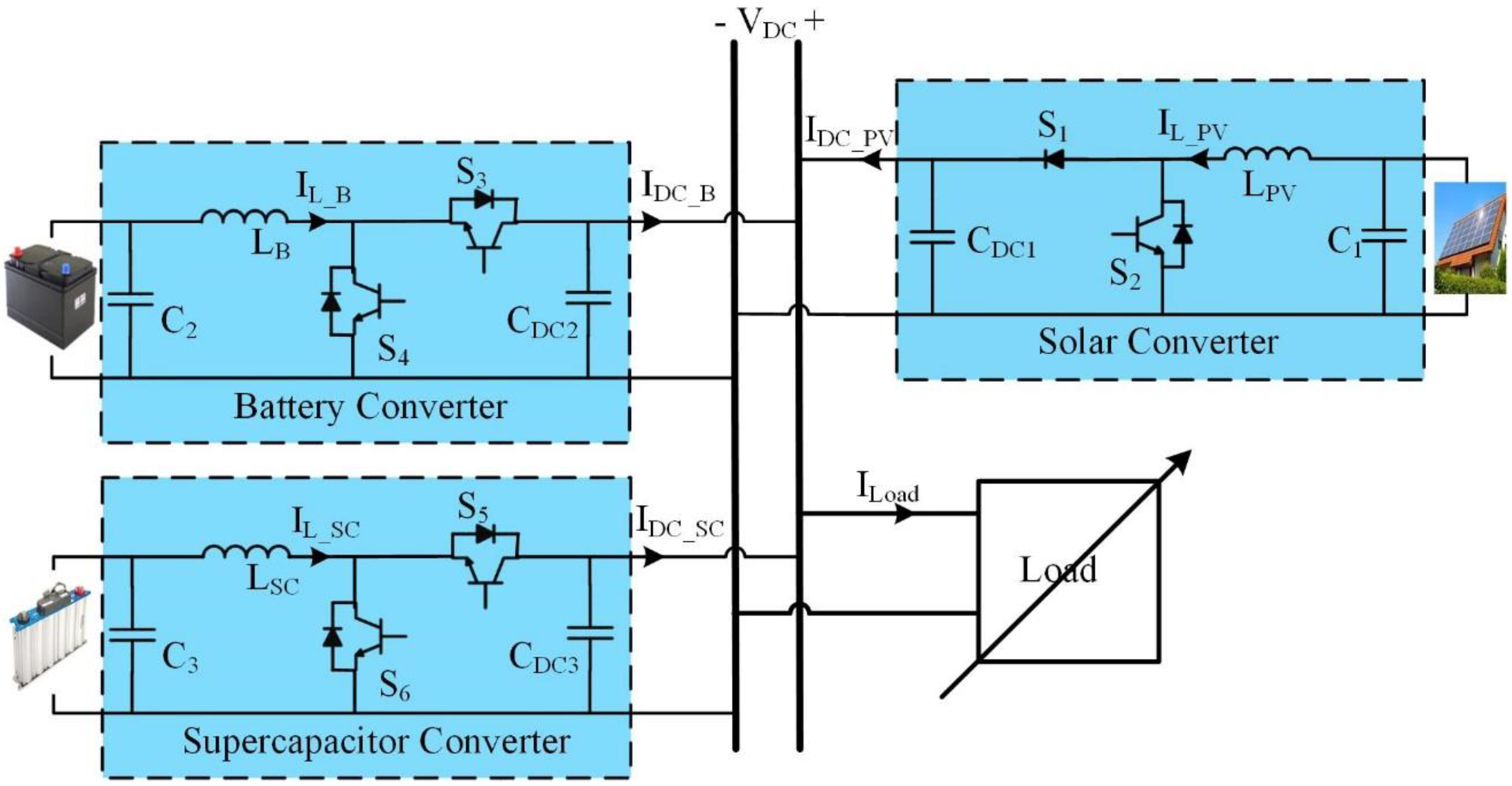
The DC nanogrid considered in this paper consists of a RES, battery and SC storage units and a variable load as shown in
Figure 1. The RES employs a uni-directional boost converter, while the storage units require a bi-directional one, typically a class C DC-DC converter. The battery and SC can be controlled as a single HESS, in which case they should be co-located, or independently what is suitable for distributed energy storage units, as proposed in this paper. The single-bus DC nanogrid is controlled in a decentralized way with a hierarchical structure based on DBS and droop control. However, no communication means for energy management is considered in this paper. DBS uses the DC bus voltage itself as the communication link to coordinate the operation of DERs in a decentralized way. With droop control, the current (power) injected by each DER in the nanogrid depends on its threshold voltage (
VNL), where the injected current is zero, and its droop slope (factor)
Rd as shown in Equation (1). The latter determines how the injected current varies as a function of grid voltage variations.
where;
In the hierarchical structure, DBS is the primary control level of the nanogrid. The DC nanogrid considered in this paper has a nominal voltage of 1 pu. It was conceived to operate with a voltage regulation of about ±5%, giving an operating DC bus voltage between 0.95 pu and 1.05 pu. In the case of the RESs, the threshold voltage is often taken as
VNL_PV = 1.05 pu, higher than the threshold voltage of the energy storage unit or HESS,
VNL_ST = 1 pu. In the concept of DBS, it gives the RESs, if available and producing power, the highest priority to feed the loads. As shown in
Figure 2, by the blue curve, the solar converter operates in three regions: droop, constant power, and constant current-limited with unidirectional power flow. When the DC bus voltage is between 1.05 pu and 1.025 pu, the solar converter operates with droop factor
RdPV. Therefore, the solar generates the maximum power at
VDC = 1.025 pu and starts to operate at maximum power point tracking (MPPT) with the rated solar irradiance. When the PV has a maximum power less than the rated power, due to a lower solar irradiance, the solar converter should start to operate at MPPT before the DC bus voltage drops below 1.025 pu, what can be done by “reprogramming” the V-I curve of the solar converter, as shown in the dashed line in
Figure 2. For instance, the solar converter should start to operate at MPPT with a DC bus voltage of 1.029 pu with a maximum power of 90% from the rated power. When the DC bus voltage drops below 0.95 pu for rated solar irradiance, the solar converter starts to operate in the constant current-limited mode.
The V-I curve of the energy storage unit or HESS is the red curve in
Figure 2, presenting only droop and current limiting modes. When the DC bus voltage is between 1.025 pu and 0.975 pu, the storage converter operates with droop factor
RdST. Otherwise, it operates with a constant (rated) negative current at a DC bus voltage higher than 1.025 pu and constant positive current at a DC bus voltage lower than 0.975 pu. The storage unit charges when the DC bus voltage is higher than 1 pu, as indicated by a “negative injected current.” Conversely, it discharges at DC bus voltages less than 1 pu.
3. Conventional and Proposed Control Schemes of the Battery-SC HESS
In the conventional approach, shown in
Figure 3, the battery and SC are co-located and controlled as a HESS to realize a given V-I curve or droop characteristic. The supercapacitor operates in parallel with the battery to provide short bursts of power that eliminate the high-frequency components in the transient battery current response, so that the battery current has a smooth transition. In a DC nanogrid with droop control, the DC bus voltage is sensed, and an outer voltage loop with a proportional (P) controller, which corresponds to the droop action, produces a reference current to be realized by the battery and the SC converters. The slow and fast changing components of the reference current are split, by means of either a high-pass filter (HPF) or a low-pass filter (LPF). The slow ones are used as a reference for the inner battery current control loop, while the fast ones are used for the inner SC current control loop. The bandwidth of the outer voltage loop is typically 10% of the inner current loops. It is very effective in preventing fast varying currents from flowing through the battery. The control scheme of the SC also includes a voltage loop to keep the voltage of the SC within a desired range, typically 50% to 100% of its rated value. By setting the reference voltage at 79% of the rated value, the SC has a state-of-charge with equal energy capacity to supply and absorb power before reaching the limit voltage values. Its bandwidth is typically 10% of that of the voltage (droop) loop of the HESS. Splitting the total current (
IL_Storage) supplied by HESS into average components, that is the battery reference current, and the transient power component, that is the SC reference current, helps in improving the operation of the battery but it does not improve the DC bus voltage dynamics. Moreover, a common voltage loop is used to generate the total current (
IL_Storage) to be supplied by the HESS, which requires a communication means between the battery and the SC converters. This is not appropriate to be used in nanogrids with DERs operating in a decentralized way with droop control and DC bus signaling.
In the proposed approach shown in
Figure 4, the SC interface is controlled independently from the battery one, which will allow it to provide additional services to the DC nanogrid. This is achieved by selecting a droop factor for the SC interface much smaller than the battery’s, which is equivalent to a higher gain for its outer DC bus voltage loop. As a result, it will provide a much larger current reference for a given DC bus voltage variation, what should improve the dynamic voltage regulation. Recall that the SC is inherently capable of providing/absorbing high bursts of power. However, due to its low energy density, the duration of the power bursts should be limited, what can be done by introducing a HPF with suitable time constant in the input of its inner current loop. On the other hand, there is no need for a LPF in the input of the inner current loop of the battery interface, assuming that the SC interface will prevent sharp variations in the DC bus voltage and consequently sharp variations in the reference current of the battery interface.
The proposed control scheme has two parameters for design: the droop factor (RdSC1) and the time constant () of the HPF. The first has a major impact on the peak value of the injected current, due to a sudden DC bus voltage variation, while both affect the duration of the high burst of power. Based on Equation (2), the droop factor RdSC1 defines how much current is injected/absorbed into/from the DC grid as a function of a voltage difference (VNL and VDC). If the SC unit is to provide meaningful current bursts for assisting with dynamic voltage regulation, its droop factor should be much smaller (approximately 2% to 10%) than that of the battery converter. On the other hand, it is desirable that this current burst lasts just long enough to mitigate the DC bus voltage variations so as not to drain/supply much energy from/to the SC unit. This can be accomplished with the appropriate choice of the time constant () of the HPF.
In order to select these parameters, a dynamic model of the system, including the small-signal model of the SC interface (class C DC-DC converter) as shown in
Figure 5, is considered. Assuming that the solar converter operates in the MPPT mode, it is modeled by a virtual constant current source. The battery converter operates with droop control and can be represented by a Thévenin model with a voltage source equal to the threshold voltage and a resistor equal to the droop factor (
RdB) of the battery converter [
17]. DC bus voltage variations shall occur mostly due to load variations.
Figure 5 shows the small-signal model of the system, based on [
6,
18]. It includes the inner boost inductor current (
IL) control loop with a PI-type controller and the duty-cycle to inductor current transfer function (
Gdi(
s)) of the converter. The outer (droop) voltage control loop is based on a droop factor (
RdSC1), that concerns the DC bus voltage (
Vdc) and the reference injected current (
Idc). The slow SC voltage control loop is neglected in this analysis. A first-order high-pass filter (HPF) with time constant
is used in this work, where
The power converter is assumed to be ideal and a gain factor (1-
D) is employed to refer quantities from the DC bus to the SC side of the power converter, and vice-versa. A time constant for the DC nanogrid side (
) is defined from the droop factor of the battery converter (
RdB), which is much lower than the equivalent load resistance (
RL), and the output capacitance of the SC interface (
CDC3). Thus,
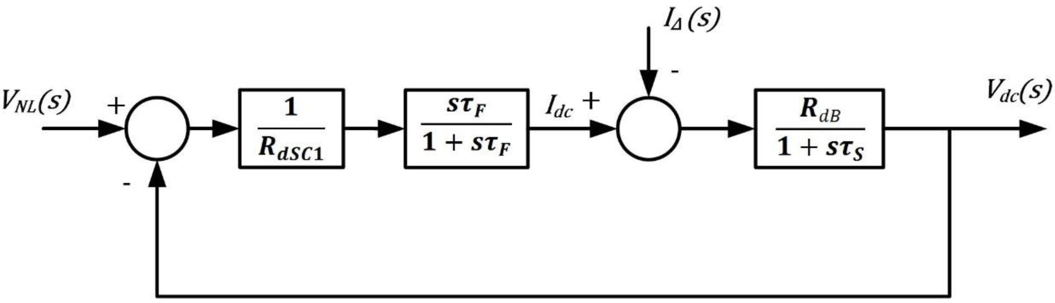
Since the outer voltage (droop) loop has a much lower bandwidth than the inner current loop, the latter, which presents a zero error in steady-state due to the PI controller, can be simplified to a unity gain. Then, one can assume that there will be no variations in
VNL_SC and that load and PV current variations can be combined in a single element (
IΔ). Finally, the block diagram describing the dynamics of the system can be further simplified as shown in
Figure 6.
The system’s transfer function (
GT) is given by:
where
and
The characteristic equation of the system is:
It can be represented in terms of the damping ratio (
) and the natural frequency (
) as:
where
and
The impact of the value of the droop factor (
RdSC1) and time constant (
) of the HPF on the dynamic response of the system can be observed by means of the root locus method. The latter determines the location of one of the open loop roots while the former affects the position of the closed loop roots.
Figure 7 shows the root locus of the system for
RdB = 0.289 Ω and
CDC3 = 1500 µF. For the analysis, the cut-off frequency of the HPF is taken as 50 Hz. Since transfer function
G, (6), has two negative real poles and one zero at the origin, the system is stable for any gain
k. As
k increases (
RdSC1 decreases), one closed loop real root moves towards the infinity and the other, dominant, towards the vertical axis. For a high enough
k, one can neglect the non-dominant root.
As mentioned before, small values for
RdSC1, from 2% to 10% of
RdB, should lead to a large enough burst of current to assist with dynamic DC bus voltage regulation what should also prevent the battery from supplying fast changing currents. Once the value of
RdSC1 is selected, one can compute
based on the desired duration of the high burst of power (
Ts). For a system (
GT) with a dominant real root, one can say that
Ts = 3
τ, where τ is the time constant of the dominant root. For a system with a negligible root,
and
Then, for a specific desired time constant
τ, one can solve (12) with
from (10) and
from (11) to find
. A closed form equation for
is not straightforward. Alternatively, one can obtain the value of
from a plot.
Figure 8 shows the value of 1/τ as a function of
for different values of
RdSC1/
RdB and for a system with
CDC3 = 1500 µF. As an example of usage of this approach, for
RdSC1 = 0.05
RdB, a HPF with
gives the settling time
Ts = 0.22 s. For
RdSC1 = 0.1
RdB, and the same HPF (
), the settling time becomes
Ts = 0.12 s. Alternatively, the original settling time (0.22 s) can be achieved with
RdSC1 = 0.1
RdB and a HPF with a time constant of
. It should be noted that as one decreases
RdSC1, to have a higher burst of current and a smoother DC bus voltage variation following a sudden power unbalance in the DC nanogrid, a smaller time constant (
) of HPF is needed for a given settling time. In addition,
Figure 8 also shows the impact of
on the damping ratio
and the natural frequency
.
4. Case Study
As a case study in this paper, a 48 V DC nanogrid consisting of a PV-based RES, a battery unit, a SC unit and a variable load is considered. The PV panel provides a maximum power of 213 W with 7.35 A and 29 V at rated solar irradiance. Due to converter losses, it is considered that the maximum (rated) injected power by the PV unit is 200 W. In order to comply with the voltage levels presented in
Section 2, the DC bus voltage should vary between 49.2 V and 45.6 V in the MPPT region, where the solar converter would inject 4.1 A and 4.4 A, respectively.
In the performance investigation to be conducted in the following Sections, the conventional control scheme for the HESS will be compared to the proposed one, which can also be used for non-co-located battery and SC units. The droop factor of the HESS (
Rd_ST) is 0.289 Ω and the cut-off frequency of the LPF for the frequency split is 43.5 Hz. The HESS’ threshold voltage (
VNL_ST) is 48 V and the current limit value is the maximum current supplied by the PV converter (
IST-c =
IPV-c = 4.4 A). Concerning the proposed scheme, the threshold voltages of the battery and SC converters,
VNL_B and
VNL_SC, are equal to
VNL_ST and their rated currents are equal to the maximum current supplied by the PV converter (
IB-c =
ISC-c =
IPV-c = 4.4 A). The droop factor of the battery converter is
RdB =
Rd_ST = 0.289 Ω, while that of the SC, which as discussed in
Section 3 should be 20 times lower than the battery’s, is
RdSC1 = 0.0145 Ω. The cut-off frequency of the HPF for the proposed SC control loop was calculated as described in
Section 3 for
Ts = 0.22 s and is equal to 43.5 Hz.
Regarding the power electronic interfaces, the DC-DC converters of all elements are very similar, with the exception of the unidirectional feature of the RES. They are realized with a single three-phase DC-AC converter as shown in
Figure 9, for simulation studies and in the experimental set-up. The capacitor of the DC bus (nanogrid) voltage is equal to 1500 µF. LC filters (100 µH and 470 µF) are connected between the mid-points of the three-phase inverter legs and the storage and the source elements, to create the classical class C DC-DC converters. The converters operate with pulse-width modulation (PWM) and a switching frequency of 20 kHz.
The same current control loop can be used for all DERs. A PI type-III controller was designed for the same equivalent plant with a transfer function shown in (13) [
6,
18]. They were designed for a crossover frequency of
fx = 2 kHz (10% of the switching frequency) and phase margin of
PM = 80°. The following plant parameters were assumed:
VDC = 48 V,
IDC = 4.44 A,
R = 10.8 Ω,
L = 100 µH,
C = 1500 µF, and
D = 0.46 for
VPV =
VBat =
VSC = 29 V.
R was selected as the maximum load that could be supplied by the RES alone. At the end, the PI controller parameters are computed as
KPI = 0.0114, τ = 171 µs and
TP = 37 µs.
5. Simulation Results
MATLAB/Simulink is used for simulation studies. The objective is to investigate the potential benefits of an independently controlled SC unit in the dynamic regulation of the DC nanogrid voltage. Ideally, this should not affect the ability of the SC unit to mitigate the high frequency and fast changing currents in the battery. In order to test this feature, the solar converter operates in MPPT while the power demanded from the DC nanogrid varies between no-load and full-load. From t = 0 s to 0.05 s, there is no power demanded from the DC nanogrid, and the storage unit(s) absorbs all the power provided by the RES, around 200 W. Then a full-load impedance of 5.2 Ω is connected to the DC nanogrid to be supplied by both the RES and storage unit(s), both at full power. This operating condition remains until 0.05 s when the load is removed. This corresponds to the largest normal disturbance to be faced by the DC nanogrid and will be used to compare the performance of the proposed control scheme with the conventional one with a HESS. The parameters of the system are as stated in previous Sections. (The battery and SC were represented by ideal DC voltage sources of 24 V and 28.4 V, respectively.)
Figure 10 shows the results of the key system waveforms for the conventional scheme. Initially at no-load, the DC nanogrid voltage (top screen) is about 49.25 V. The solar converter operates in the MPPT mode with a boost inductor current (average) of around 7.35 A, bottom screen. The average current absorbed (negative sign) by the battery is 8.4 A while that of the SC is zero, as expected. Following the load step, the SC current increases very fast reaching a peak value of 10 A, while the battery’s increases more slowly, as desired, until it supplies all the HESS current. The DC bus voltage reaches the steady-state value of 46.75 V in 17 ms. A similar behavior, in terms of current magnitudes and settling times, can be observed when the load is removed at t = 0.3 s and the HESS has to, again, absorb rated power.
Figure 11 shows the performance of the system, for the same load transients, with the proposed control scheme. The values of the waveforms in the steady-state for the no-load condition are virtually the same as for the conventional HESS control scheme. Following the full-load step variation, one can see that the DC bus voltage decreases much more slowly than with the conventional HESS control approach. This is due to the way the SC converter is controlled, injecting a higher current and for a longer time to slow down the reduction of the DC bus voltage. At the same time, as expected, it slowed down the increase of the battery current. This was done indirectly, via the DC bus voltage, without any signals exchanged between the control loops of the battery and SC converters. Just before t = 0.3 s, the values of the waveforms obtained with the proposed scheme are very similar to those obtained with the conventional HESS scheme. Then, following a step load rejection, to no-load, the proposed scheme provides a similar improvement in the DC bus voltage variation and in the battery current variation. It is worth mentioning that besides using the proposed control scheme, one should also make sure that the SC is large enough to provide/absorb the required compensating energy without significant changes in its voltage level and that the boost inductor of the SC converter will not saturate with the increased current. Considering the relatively short action time of the proposed control scheme for the SC converter, it should not be necessary to increase the current ratings of the semiconductor switches.
6. Experimental Results
A DC nanogrid with a RES, two energy storage units and a variable load was assembled in the laboratory. An Agilent Solar Array Simulator (SAS) (E4350B) was used to emulate a solar array. It was programmed to provide a maximum power of 213 W with 7.35 A and 29 V at rated solar irradiance. Maxwell supercapacitor modules (BMOD0165 P048) of 165 F with a rated voltage of 48 V were employed for the energy storage units. One is used as a battery and the second is used as a SC. As in the simulation studies, the “battery voltage” was adjusted to 24 V and the SC’s to 28.4 V. Regarding the power electronics interface, a Semikron “MiniSKiiP 8 Three-phase 1200 V Power board”, with a
MiniSKiiP 83 AC power module and a
SKHI61 IGBT driver, was used in this study. The values of passive components, control parameters, and so on, used in the experimental set-up are those presented in
Section 4. The control schemes are implemented with a dSPACE DS-1103 rapid prototyping system with a 20 μs time step. The dSPACE code was generated by Simulink C coder by means of Real-time interface (RTI), which converts the control diagram from MATLAB/Simulink into dSPACE code. This does not provide the fastest and the shortest code, but it is sufficient in experimental proof-of-concept tests. Eight parallel switchable 44 Ω resistors were used for realizing the full DC nanogrid load impedance. A picture of the experimental set-up is shown in
Figure 12.
Having demonstrated the improved performance of the proposed scheme over the conventional HESS control scheme by means of simulations, experimental results are provided to demonstrate the feasibility of the proposed control scheme. The focus of this Section is on the impact of different system parameters obtained using the proposed design approach.
The first case, which was also presented in the simulation studies, concerns a SC interface with a droop factor
RdSC1 = 0.0145, 20 times lower than the battery’s for providing a peak current of 20 times that of the battery for a given DC bus voltage variation. It employs a HPF with a time constant
, computed to give a settling time of
Ts = 0.22 s. The key waveforms of the system are shown in
Figure 13 for a no-load to full-load (5.2 Ω) variation and back to no-load. At no-load, the DC bus voltage is initially at 49.2 V and it decreases slowly to 46.8 V at full-load in the steady-state. (The screen shows 0.4 V/div.) The load current increases in a step-like manner from 0 A reaching 8.45 A in steady-state (1.3 A/div). The SC (inductor) current, initially at 0A, increases very fast following the load step, reaching a peak value of about 20 A. Then, it decreases exponentially reaching 0 A after about 0.24 s. The battery (inductor) current changes slowly from –8 A, when it absorbs the full PV power at no-load, to 8 A, when it provides to the DC bus the same amount of power as the PV converter, at full-load (4 A/div). The PV (inductor) current remains virtually constant since it operates with MPPT with rated solar irradiance. The experimental waveforms match very well with the simulation ones.
In the second case, a larger droop factor (
RdSC1 = 0.0289 Ω), which is 10% of the battery’s, is used. Thus, the SC converter should provide a lower contribution during transient conditions. The time constant of the HPF is calculated for the same value (
Ts = 0.22 s), resulting in
.
Figure 14 shows the transient response of the system, with the abovementioned parameters, for the no-load to full-load and back to no-load transitions. By comparing the results with the previous ones, one sees that the DC bus voltage presents a larger step decrease, due to a lower peak SC (inductor) current, but it reaches the same steady-state value at full-load with the same delay as before, because of the design specification (settling time) used in both cases. The battery (inductor) current increased a bit faster as a result of the lower DC bus voltage during the transient condition. The PV (inductor) current remains virtually the same, identical to the previous case.
The last case concerns a SC converter with a large droop factor (
RdSC1 = 0.0289 Ω = 0.1
RdB), and with a HPF designed for a settling time (
Ts = 0.12 s) resulting in
. In such a case, the SC converter should present the lowest value, in terms of current magnitude, and a shorter contribution during the transient conditions of the three cases tested experimentally. As observed in
Figure 15, its impact on the dynamic DC bus voltage regulation and battery (inductor) current waveform is obviously lower. However, this can be achieved with lower energy required from the SC and potentially a smaller (capacitance) SC, for the same SC voltage variation.


