Review

HELL: High-Energy Electrons by Laser Light, a User-Oriented Experimental Platform at ELI Beamlines

by
Tadzio Levato
1,*,
Stefano Bonora
2,
Gabriele Maria Grittani
1,3,
Carlo Maria Lazzarini
1,
Muhammad Fahad Nawaz
1,
Michal Nevrkla
1,
Leonardo Villanova
1,
Roberto Ziano
1,†,
Silvano Bassanese
4,
Nadezhda Bobrova
5,
Katia Casarin
4,
Edwin Chacon-Golcher
1,
Yanjun Gu
1,
Danila Khikhlukha
1,
Daniel Kramer
1,
Marco Lonza
4,
Daniele Margarone
1,
Veronika Olšovcová
1,
Marcin Rosinski
6,
Bedrich Rus
1,
Pavel Sasorov
1,
Roberto Versaci
1,
Agnieska Zaraś-Szydłowska
6,
Sergei V. Bulanov
1 and
Georg Korn
1
add Show full author list remove Hide full author list
1
Institute of Physics of the ASCR, ELI Beamlines Project, Na Slovance 2, 18221 Prague, Czech Republic
2
CNR-Institute for Photonics and Nanotechnology, Trasea 7, 35131 Padova, Italy
3
Czech Technical University in Prague, FNSPE, Brehova 7, 11519 Prague, Czech Republic
4
Elettra—Sincrotrone Trieste S.C.p.A., 34149 Basovizza Trieste, Italy
5
Keldysh Institute of Applied Mathematics RAS, Moscow 125047, Russia
6
Institute of Plasma Physics and Laser Microfusion, 01-497 Warsaw, Poland
*
Author to whom correspondence should be addressed.
Now at Officina Stellare s.r.l. Via Della Tecnica, 87/89 I-36030 Sarcedo (VI), Italy.
Appl. Sci. 2018, 8(9), 1565; https://doi.org/10.3390/app8091565
Submission received: 24 June 2018 / Revised: 16 July 2018 / Accepted: 8 August 2018 / Published: 5 September 2018
(This article belongs to the Special Issue Laser-Driven Particle Acceleration)

Abstract

:
Laser wake field acceleration (LWFA) is an efficient method to accelerate electron beams to high energy. This is a benefit in research infrastructures where a multidisciplinary environment can benefit from the different secondary sources enabled, having the opportunity to extend the range of applications that is accessible and to develop new ideas for fundamental studies. The ELI Beamline project is oriented to deliver such beams to the scientific community both for applied and fundamental research. The driver laser is a Ti:Sa diode-pumped system , running at a maximum performance of 10 Hz, 30 J, and 30 fs. The possibilities to setup experiments using different focal lengths parabolas, as well as the possibility to counter-propagate a second laser beam intrinsically synchronized, are considered in the electron acceleration program. Here, we review the laser-driven electron acceleration experimental platform under implementation at ELI Beamlines, the HELL (High-energy Electrons by Laser Light) experimental platform .

1. Introduction

Laser-plasma electron acceleration [1] allows for generating high-energy particles in relatively short distances as compared to conventional linear accelerator systems, thus allowing for such energetic beams also at small and medium size research infrastructures [2,3,4,5]. Nowadays, laser-accelerated electron beams are produced with table-top laser systems from TW to PW peak power [6,7,8,9,10], thus accessing a broad energy range up to the multi-GeV level [11].
The use of an ultrashort laser pulse driver enables at the same time the possibility to pump and probe a sample with secondary laser or particle beams, thus offering ultrafast temporal resolution in the 10-fs range. These features are extremely interesting for several potential multidisciplinary applications [12]. On the other hand, the non-optimal electron beam quality in terms of pointing stability, average energy and energy spread impose severe limitations to the usability of such beams. At the same time, such challenge requirements have increased the number of test experiments aiming to improve the beam reliability for applications. As recently shown, innovative injection approaches can stabilize the average electron energy and limit the energy spread down to 1% [13]. These achievements are promising and encouraging for further improvements of the accelerated electron beam features, but at the same time, also allow for reaching a sufficient level for their use for specific applications [12]. The ELI Beamlines project [2] main mission is to deliver laser-produced secondary beams to the scientific community, both for applied and fundamental research in different fields. For this reason, different user-oriented beamlines are being implemented with the goal of delivering particle and radiation with unique features, especially when compared to conventional facilities. Since the capability to produce secondary beams using ultra-high-power laser systems is still in a fast development phase, some of these beamlines are geometrically organized to be flexible and modular to offer the possibility to arrange advanced optical setups for future development of the source or just the preparation of a complex user experiment. This is, for example, the case of the High-energy Electrons by Laser Light (HELL) experimental platform, a project that is mainly based on the laser wake field acceleration (LWFA) concept [1,5,11,14,15].
Figure 1 shows a typical three-dimensional (3D) Particle In Cell (PIC) simulated electronic density of the LWFA process using the code EPOCH [16] on the ELI Beamlines clusters ECLIPSE. In this case, a 0.2 PW, 30 fs laser pulse is focused to a waist of 19.8 um onto a supersonic gas-jet generating an electron plasma density of 1.5 × 10¹⁸ e/cm3. This condition is shown to produce strong electron injection, already at 1 mm of propagation in the plasma, as its evident at the center of the dark region also called wake-field.
Typically, such an acceleration regime [14] requires long focal lengths; furthermore, a laser beam counter-propagating with the accelerated electrons is requested for fundamental studies [15,17]. Such requirements in terms of electron energy and setup flexibility, in the case of PW-class lasers suggest to use two separate vacuum chambers: one for the laser driver, which includes the main focusing optics, and one for the acceleration areas. These two chambers are then connected through vacuum pipes to allow for the propagation of the laser beams. Since LWFA is rapidly evolving and experimentally observed maximum energies are quickly increasing [11], a value of 10 GeV is used for the implementation of electron spectrometry into the HELL platform, as well as radioprotection considerations. In this manuscript, we provide a general overview of the capabilities of the HELL platform, reporting its main technical features and the main related research and development activities, with the intent to highlight the experimental potentialities that such a platform will offer to the ELI user’s community.

2. The Experimental Platform HELL: High-Energy Electrons by Laser Light

This section describes the HELL platform technical details and it is divided in four subsections. The first one describes the HELL optical setup providing an overview of the different experimental capabilities: the variable configuration to position off-axis parabola with very different focal lengths, which is self-synchronized with a counter-propagating laser beam, and the use of dedicated deformable mirror (DM) to improve the focal quality or to apply the requested focus shaping capabilities. The following subsection describes conceptually the basic set of single-shot laser-pulse diagnostics available, which will enable to correlate shot-to-shot each experimental data characterizing (i) the plasma interaction, (ii) the accelerated electron beam, and (iii) the user sample irradiated by electrons, with the corresponding laser pulse parameters. This will be crucial for further optimization or development of novel acceleration schemes, thus to overcome the current experimental limitations. An interesting tool is for example the “focal shaping” enabled by the deformable mirror to enhance some specific feature of the considered experimental scheme. The third subsection describes the basic diagnostics used to monitor the laser-generated plasma (optical imaging and interferometry), the basic electron bunch diagnostics with corresponding calibrations and the user station, which allows irradiating any user sample in an automatic way once the electron bunch parameters are fixed. The last subsection describes the electron beam dump conceived for electron beam energy up to 10 GeV, together with the simulated dose distribution and secondary particles.

2.1. The 10 Hz, 1 PW Laser Driver “L3”

The main laser considered in the first stage of implementation of the HELL platform at ELI-Beamlines is called high-repetition-rate advanced petawatt laser system (L3-HAPLS), which is designed to deliver PW pulses with energy of at least 30 J and durations <30 fs, at a repetition rate of 10 Hz [4]. It is the first all diode-pumped, high-energy femtosecond PW laser system in the world. The laser was developed at Lawrence Livermore National Laboratory (Livermore, CA, USA), with ELI-Beamlines (Dolní Břežany, Czech Republic) cooperating on the development of short-pulse diagnostics, short-pulse subsystem controls, timing, and delivering the PW vacuum compressor.
The system was demonstrated to provide highly stable continuous operation at specified energy and pulse duration. HAPLS will be the world’s highest average power Petawatt laser system. Even if the HELL project is organized to accommodate at the same time different laser beams that are available at ELI-Beamlines, including the 10 PW (called “L4” [4]) laser interesting for specific interaction regime [17,18], in the following, we will mainly focus on the use of the L3 laser. All of the optical simulation results depicted in the article (related to the near and far-field) are carried out by commercial software (Virtual-Lab) based on Maxwell solver field tracing. Figure 2 (left) shows the modelling of a spatial distribution of the L3 laser operating at a central wavelenght 820 nm in ideal conditions at the compressor output. The squared super-gaussian distribution gives a value of 1/e^2 of 226 mm. Together with the ideal case, Figure 2 (right) shows an L3 spatial distribution in which artificially generated intensity modulations (speckle, white Gaussian) were introduced to consider diffraction effects during the propagation in vacuum. In Figure 3, a phase-front distortion is shown, as introduced in the artificially modulated case to verify the capability of the entire optical system to correct potential phase-front modulations.

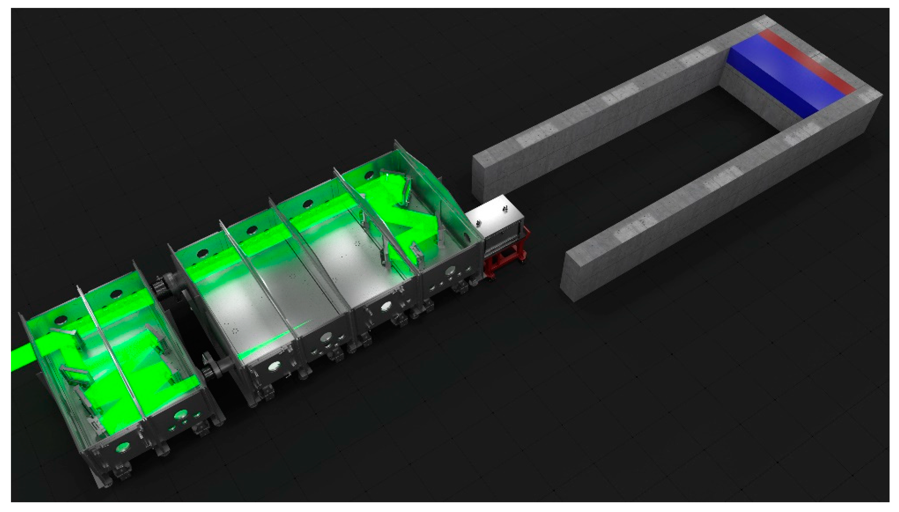
2.2. The HELL Platform

This correction can be applied thanks to the use of a DM available in the HELL optical setup. For this reason, in the first set of optical simulations a free propagation of the laser in vacuum is considered starting from the compressor output up to the HELL deformable mirror (the total distance is 100 m). At the end of such free-space propagation, the resulting phase-front is simulated to be corrected to the best level reachable by using the 64-actuators of the given deformable mirror (see Section 2.3.1Section 2.3.3 for further details). The phase front at a distance of over 100 m was extracted for virtual DM correction through soft-ware. Wave front aberration correction while using Zernike Polynomials generated a corrected phase front file, which then was propagated back from the point that it was extracted, to see the improved effect in the far-field.
Figure 3 (right) shows the residual wave phase-front distortion after the simulated correction by the deformable mirror. Finally, the HELL off-axis parabola (OAP) focuses the beam and the simulation output is compared with the ideal case. The same simulation procedure is used for the two different focal length OAPs that are available at the HELL platform during its first phase of operation.
Figure 4 (top) shows the HELL platform configuration in the experimental hall E5 and (bottom) a detailed view of the optical setup. As it is shown in Figure 4 (bottom), the possibility to accommodate different focal length parabolas, still keeping the intrinsic synchronization of the counter-propagating beam, is considered and it can be easily achieved by shifting to the East of E5 (right in Figure 4) the interaction chamber with respect to the first auxiliary chamber. The intrinsic synchronization in any case can be tuned using the dedicated delay line (visible in Figure 4 in the right-up corner). The focal lengths of the two OAPs (initially available) have been selected while considering the two main interaction regimes of major interest for LWFA: the self-injection regime [19,20,21] and the guided regime [6]. The first regime, which typically uses higher intensity, will be realized with a 4.4 m focal length OAP, and the guided regime with a 10 m focal length OAP. A third (shorter focal length) OAP will be used to enable the counter-propagation beamon a fixed off-axis angle of about 30 deg. In future works, the description of a system to fine tune the off-axis angle will be given.
Counter-propagating pulse configuration will be used for fundamental physics studying, including studies of the radiation friction effects and the effects of nonlinear quantum electrodynamics in the interaction of the high intensity laser pulse with laser accelerated ultra-relativistic electrons [22,23,24] and extremely high intensity electromagnetic field generation within the framework of the Relativistic Flying Mirror concept [24,25,26,27].
Figure 5 shows the focal distribution that was obtained in the ideal case (left), in the artificially modulated case (center), and in the DM corrected case (right) for the 4.4 m OAP. As it is shown the correction works well, however, even after corrections (high focal quality), lateral wings coming from the squared near field of the beam are present and may affects the dynamic of a typical LWFA experiment.
Figure 6 shows the focal distribution obtained in the ideal case (left), artificially modulated (center-red) and the corrected case (right and center-blue) for the 10 m OAP.
It is worth mentioning that the side wings that are visible on the far field of a rectangular Super Gaussian beam is the natural consequence of its shape (Figure 7). However, those wings might be diminished using different techniques usually at the cost of intensity drop. We discuss those techniques later in text.
Also, in the self-injection regime, these side wings act as independent focal points and ultimately drive independent laser wake-fields, thus giving rise to wing-produced-bunches of electrons and generating, as a consequence, a mixture of electron bunches that deteriorate the main bunch parameters, as shown in Figure 8.
In the lowest intensity scenario of Figure 6, the guided regime, such wings are less capable to drive independent wake-field. On the other hand, it must be emphasized here that such regime typically makes use of specifically developed target systems. The formation of plasma by low intensity EM fields or electric discharges prior to the arrival of a high intensity pulse significantly changes the interaction of the main laser pulse with the target. Therefore, a study of the formation process is important to laser-driven electron acceleration. With the increase of available laser power the acceleration of electrons becomes increasingly sensitive to the evolution of target density profile during the interaction. A low current capillary discharge in the resistive regime may form a radial distribution of electron density that is necessary for the formation of a plasma wave guide that is capable of transporting a channeled laser beam at a distance that is much longer than its diffraction Rayleigh range [11,28,29,30].
The external edges of the capillary can suffer of damages induced by the wings present in the laser focal spot. Such problem is already reported in literature [31,32,33,34,35] and two solutions to moderate the wings are discussed hereafter: (i) the laser beam apodization and (ii) the use of the deformable mirror (see Section 2.3). Figure 9 shows the simplest conceptual scheme that is considered for the apodization simulation. After a 5 m free propagation in space, the L3 square beam is apodized by a round shape clear aperture of 210 mm, then the beam propagate for other 95 m in free space and finally is focused by the 10 m focal length OAP. The apodization of the beam is shown here only as an example and can give even better results when considering non-flat cutting apertures. A second possibility, shown again as an example, will be described below in the deformable mirror subsection (see Section 2.3). Figure 10 shows the intensity focus distribution (considering 1 PW pulse) in log color scale of the 10 m OAP in the (left-top) “square” case and (left-bottom) “apodized” case. From a qualitatively point of view, it is evident that in the “square” case, the wings are present up to the third order, while in the “apodized” case, only the first order wing peak is present. The wing-to-peak contrast comparison is improved of a factor higher than two, as shown in Figure 10 (right), where the maximum intensity profiles are renormalized to the “square” case peak value. Such comparison also shows a peak intensity reduction and a small change in the FWHM of the apodized focal spot, such effect has to be considered when selecting the best plasma density matching conditions for LWFA. The solution with the L3 square beam apodization simplifies the use of discharge-based capillary targets. Another way to improve the wing-to-peak contrast consist in a specific configuration with deformable mirror (see Section 2.3). A combination of the two methods can further enhance the wanted result.
Research and development activities in the field of capillary-discharge plasma wave-guide are in progress in order to enable the guided regime of acceleration into the HELL platform. Due to the complexity of the processes leading to plasma channel formation, computer simulations take the leading role in study of these processes. We develop a three dimensional magneto-hydrodynamic (3D MHD) code [36], which is able to model capillary discharges. The 3D MHD simulations of the capillary discharges will be accompanied by simulation of laser beam coupling with the capillary plasma as well as of the laser beam propagation inside the wave guide and of the process of injected electron bunch acceleration. To achieve the electron acceleration, we need to know the electron density distribution and its dynamics in the capillary. Design of the capillary near its ends should be taken into account to determine the time-dependent electric current density distribution, which in turn, determines ohmic heating of the discharge plasma, and, as a result, its dynamics. We also need to know the initial distribution of neutral hydrogen near the capillary orifice. For this reason, we performed simulations on initial filling of the capillary with neutral hydrogen, using 3D gas-dynamic simulations that take into account the capillary design, including filling supplies. Results of the gas simulations were used as an initial condition for the capillary discharge MHD simulations [32].
The majority of the experiments use circular cross-section capillaries. On the other hand, square cross-section capillaries have several advantages for transverse plasma diagnostics. We have modeled plasma properties inside a hydrogen-filled capillary discharge waveguide to enable the analysis of capillaries of circular and square cross-sections, implying that square capillaries can be used to guide circularly symmetric laser beams [33,34]. The MHD simulations of a hydrogen-filled capillary discharge with circular and square cross-sections under the same initial plasma density, capillary size, and the parameters of the external electric circuit showed that the calculated magnetic field, electron temperature, and density distribution in the near-axis region of the square and circular capillaries are similar. The effect of cross-section on the electron beam focusing properties was studied using the simulation-derived magnetic field map. Particle tracking simulations showed only slight effects on the electron beam symmetry in the horizontal and diagonal directions for square capillary. These results indicate that square capillaries, which allow for greater diagnostic accessibility, can be employed to guide cylindrically symmetric laser pulses and focus electron beams.
Particular attention is being focused on matching the given L3 laser focal distribution with the capillary geometry, thus avoiding damages of the capillary walls. A radial gradient of the plasma electron density suppresses diffraction of the laser beam and allows for elongating the high intensity laser-plasma interaction length up to centimeter scales. A preliminary capillary-discharge test has been experimentally performed on a 0.3 mm inner diameter, 3 cm long capillary prototype with gas feeding system, and thyratron based discharge drives. Figure 11 shows the typical electronic signals, as obtained in the test, in particular the applied voltage and the current probe of the discharge itself [35].
At the same time, it is important to note that the guided regime can also be obtained in other ways, for example, generating a plasma channel using a nanosecond laser. Plasma channels in neutral gas can be produced in the region of an elongated focus of knife-like nanosecond duration laser beam [31,36]. The laser beam is assumed to propagate perpendicularly to the long axis of the focus. We have simulated the plasma channel formation. Within the framework of the assumption that initial gas and the laser intensity along the axis perpendicular to the direction of the laser pulse propagation are homogeneous, the physical problem becomes two-dimensional. We use the magneto-hydrodynamic (MHD) code MARPLE for the two-dimensional (2D) simulations. The aim of the simulations was to study when the plasma channel becomes cylindrically symmetric, since obviously symmetric channel are preferable for waveguiding. When an effective focal length is substantially large, the shape of the focus is elongated along the direction of the laser beam propagation. In this case, the symmetrization of the plasma channel may be questionable. The 2D simulations were performed to investigate the process of symmetrization of the channel, when the asymmetry of initial channel is caused by the asymmetric deposition of the laser energy due to spatial structure of a plane focus of the laser beam. The simulations showed how to reach the regimes of symmetric plasma channel formation [31].
A first experimental test has been performed while using a combination of cylindrical and plano-convex lens to focus the nanosecond laser energy mainly in one-dimension, giving rise to a strongly elongated or line-shape focus. Figure 12 shows the simulated focal distribution an f/4.5 cylindrical lens coupled with an f/9 plano-convex lens to obtain a peak of intensity approximately of 1 × 10¹² W/cm2. It shows the simulated line-shape (or knife-like) focus of five micron extended for about 5 mm.
First experimental results were already obtained and will be described in a different manuscript.

2.3. Diagnostics for the Driver Laser Pulse

Over the L3-HALPS diagnostics itself, additional diagnostics of the CPA laser pulse are enabled at the HELL platform in different geometries. Here, we review the main configurations with the purpose of providing an overview of the typical scenario that is useful in LWFA experiments. Since laser pulse length and spectral dispersion are key parameters for LWFA experiments, the possibility to measure them directly in vacuum must be considered. A direct measure to the entire laser beam aperture require to demagnify the beam diameter down to few mm to match the wavefront sensor area. At HELL, this is simply obtained using a very thin beam splitter immediately after the main focusing parabola, which is used as a first optical element of a reflection-based telescope. Beyond the “in-vacuum laser diagnostics”, a second set of diagnostics is placed in air for a simpler access and fine tuning of the given experimental setup. Even if partial information of some laser properties is lost in air (e.g., pulse length), the “in-air diagnostics” can still be considered as a valid tool to monitor shot-to-shot fluctuations, such as laser pointing or focal spot quality. The in-vacuum wave-front-sensor (WFS) along with an in-focus diagnostics, operating at reduced laser power, enable carrying out proper calibrations of the used detectors. The use of a fast closed loop control system is very important in complex laser systems because it can strongly reduce laser pointing and focusing instabilities [37,38]. Figure 13 shows a 2D top view of the HELL auxiliary chamber with the in-vacuum WFS diagnostic area and the dedicated optical table for in-air diagnostics.

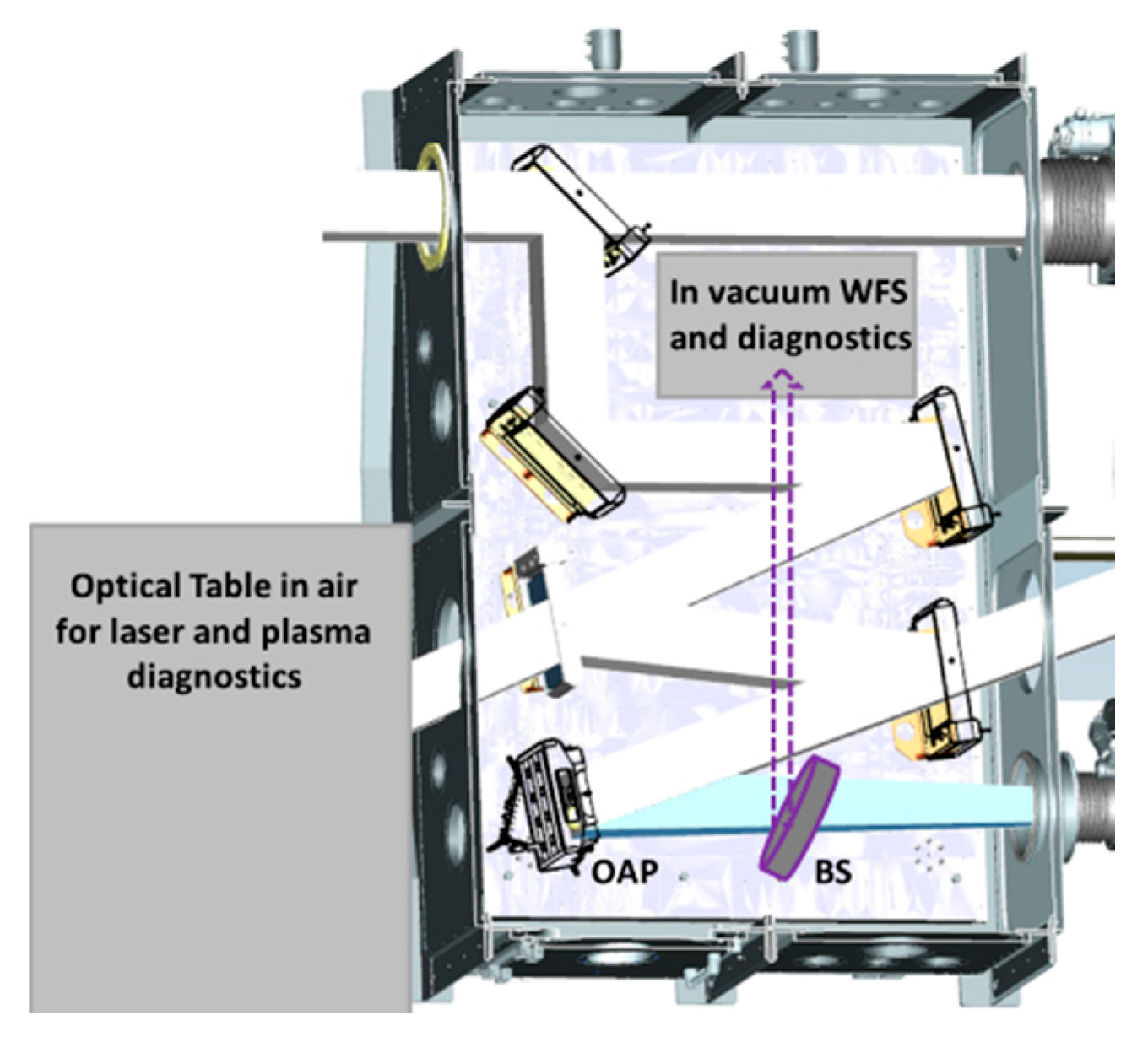
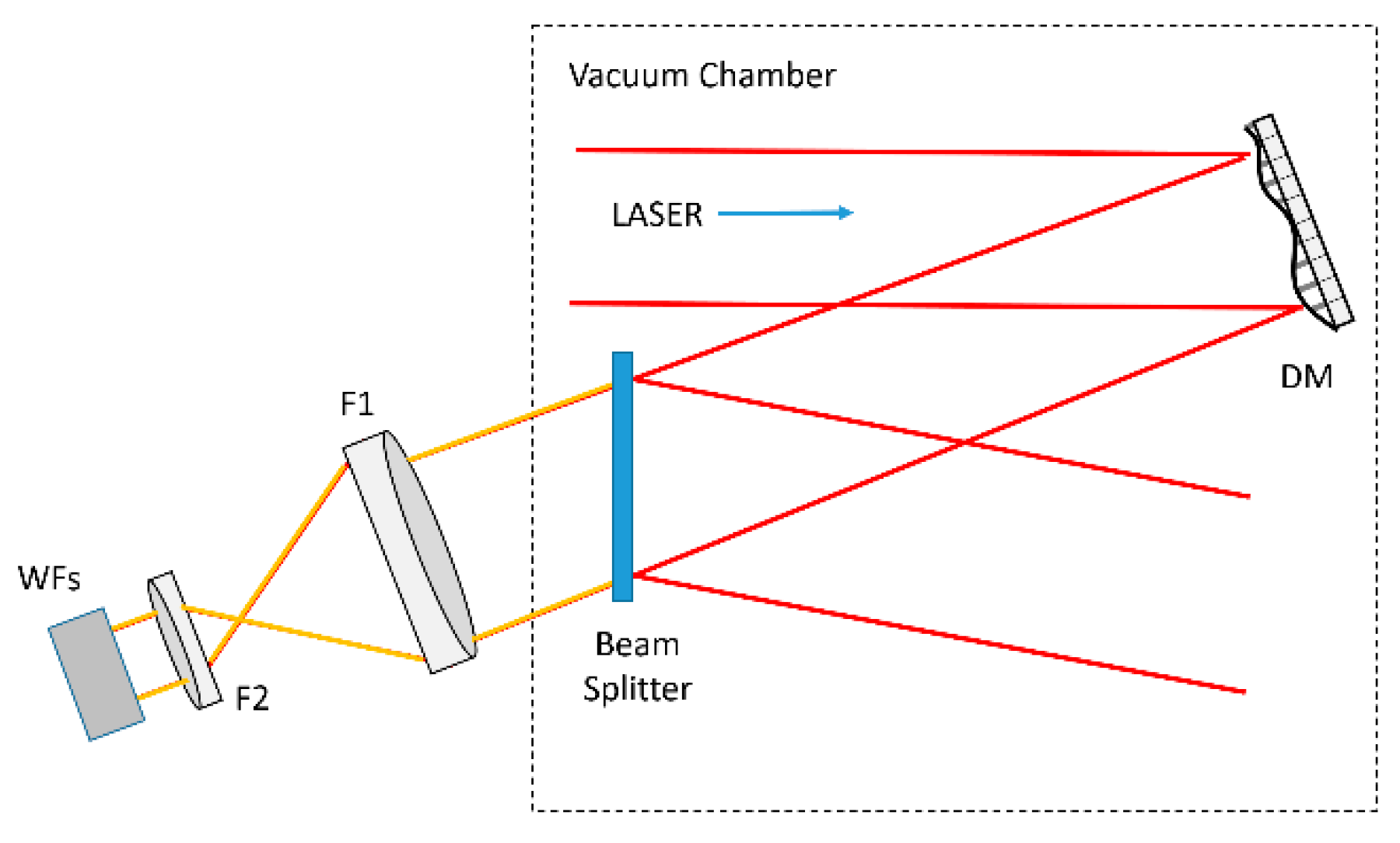
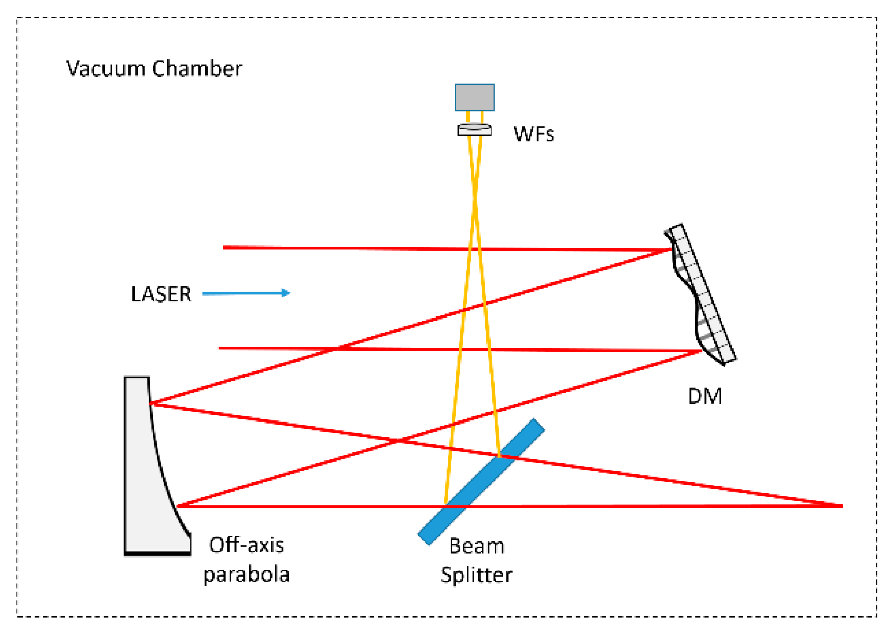
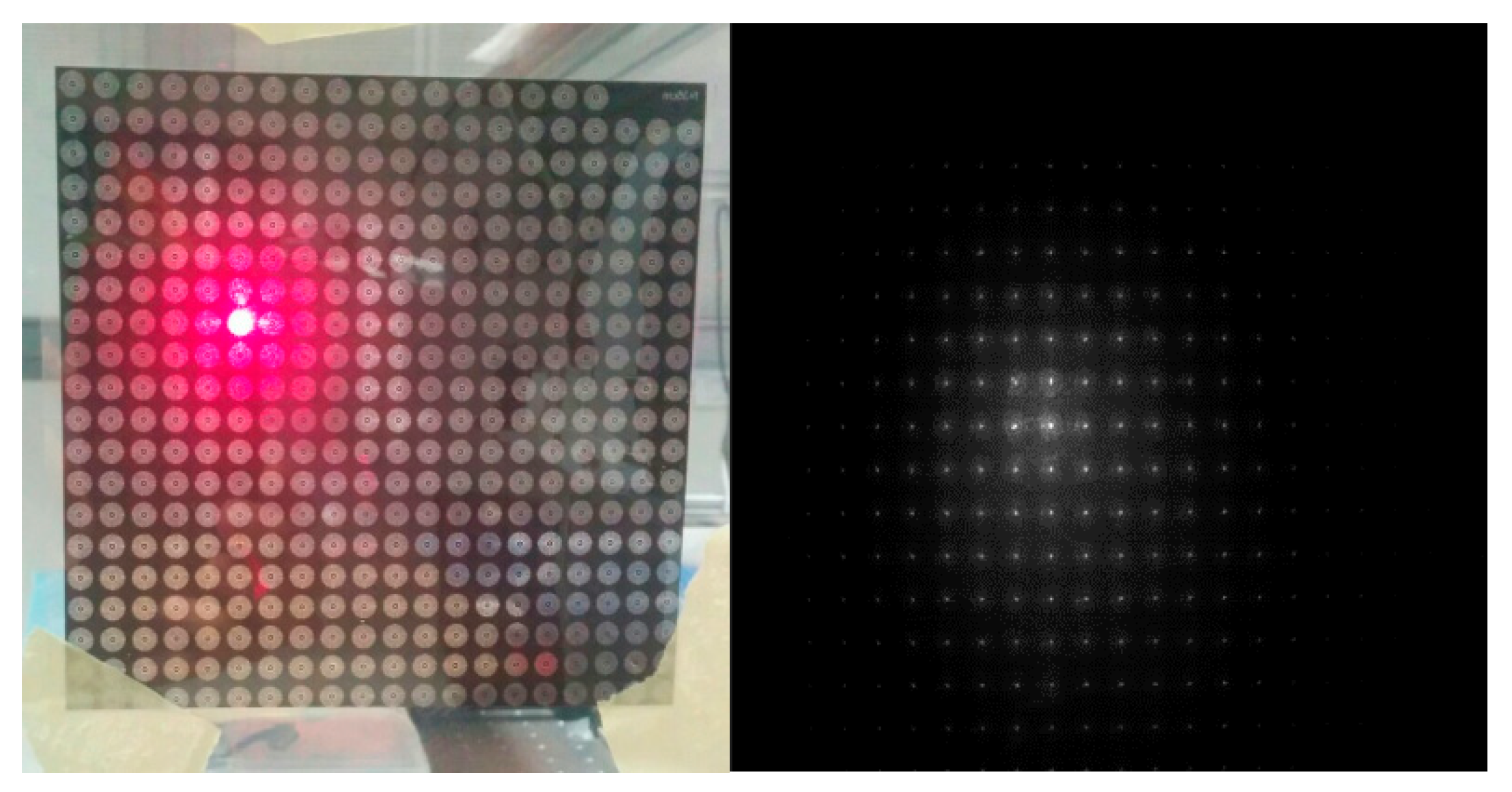
2.3.1. Wavefront Diagnostics; Examples and Tests “in Air” and “in-Vacuum”

The wavefront measurement is of fundamental importance to correct laser aberrations and to increase the stability of the laser accelerator. Sensing of the wavefront can be carried out using a beam splitter, which brings a small portion of the laser light to the wavefront sensor. Commercial Shack Hartmann wavefront sensors have a clear aperture of the order of about 5–7 mm, and therefore, it is necessary to reduce the laser beam size. One possibility is to realize a telescope, as shown in Figure 14. With this setup, it is possible to sense the laser beam aberrations and to realize a closed loop control of the deformable mirror. In this case, the adaptive optics system will correct the wavefront before the focusing parabolic mirror; therefore, any Non Common Path (NCP) aberration that takes place after the deformable mirror will not be corrected. Additional important sources of NCP aberrations are the ones relative to the sensing optical path. These aberrations include both the optical components of the telescope and the aberrations of the optical window on the vacuum chamber.
Another possibility to reduce the impact of NCP aberrations is illustrated in Figure 15. In this case, the beam splitter is positioned after the parabolic focusing mirror and the wavefront sensor is positioned after its recollimation with a lens inside the vacuum chamber. This approach strongly reduces non common paths of both arms, and is therefore preferable. Its implementation is anyway typically difficult because of the limited space in the vacuum chamber and the long optical paths. This is anyway enabled in the HELL platform.

2.3.2. Correction of Non Common Path Aberrations

Non common path aberrations are relative to wavefront errors generated in the non-common optical paths after the beam splitter that separates the laser beam and the secondary beam feeding the wavefront sensor.
The detection and the correction of NCP aberrations can be carried out in many ways. The closed loop control system reduces the aberrations up to the wavefront sensor. Therefore, any additional wavefront aberrations that are generated after the beam splitter is not sensed and not corrected, leading to a reduction of the point spread function intensity.
The NCP aberrations can be corrected exploiting the possibility to change the target aberration of the closed loop system from a flat wavefront to a wavefront opposite to the NCP aberrations [38]. The identification of the NCP aberration can be carried out with different methods: by the use of a hill climbing optimization algorithm on the PSF intensity or via indirect wavefront sensor measurement, such as curvature wavefront measurement. Alternative solution are currently being tested on large aperture (L3 size) laser beam without the needs to de-magnify, and thus, avoiding the use of an in-vacuum space-consuming telescope. Figure 16 (left) shows a large size (300 mm) array of lenses used to project on a diffusing screen the sub-focus array imaged with a simple optical camera, and (right) the sub-focus array of a large size aperture CW beam projected on a diffuser imaged with an optical camera useful for the wavefront reconstruction.
Further investigations about the spatial resolution are in progress and will be matter of future works.

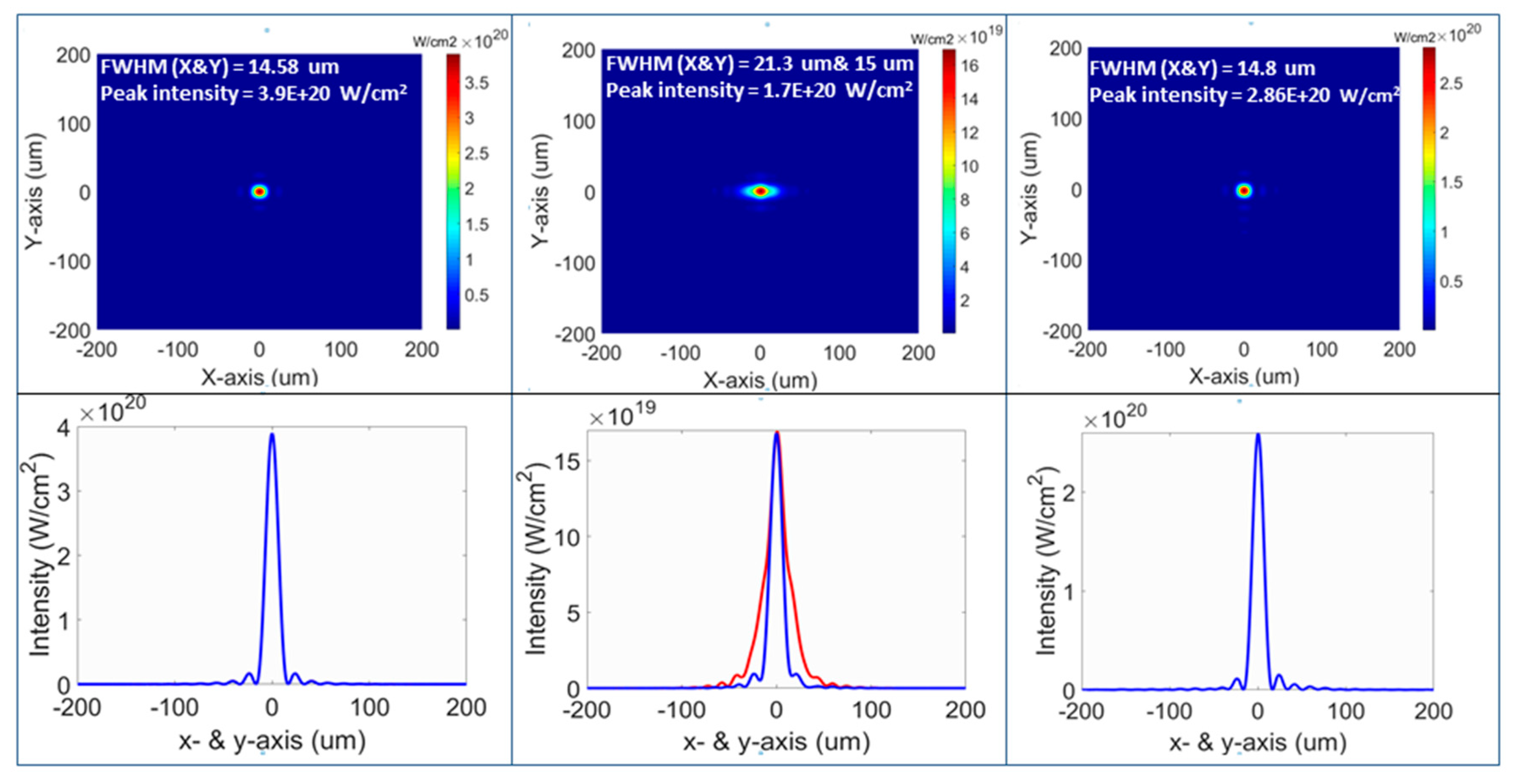
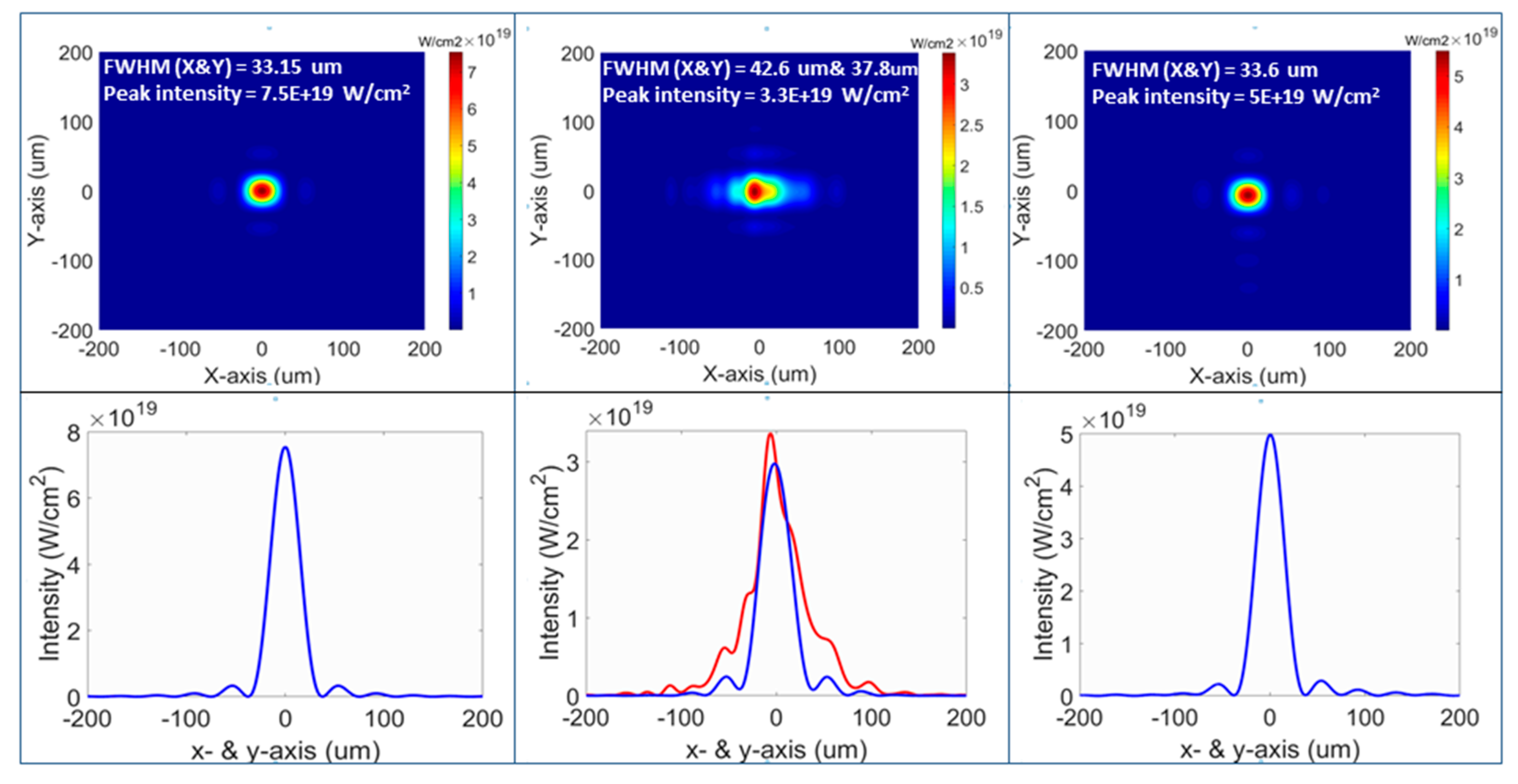
2.3.3. Beam Shaping with the Deformable Mirror

The deformable mirror is exploited both for aberration correction and also to manipulate the point spread function spatial distribution in order to enhance the interaction of the laser pulse with the target. For example, Figure 17 reports a simulation of a case where the deformable mirror is used to create a point spread function (PSF) with more contrast between the peak intensity and the side lobes intensity. Figure 17 (left) shows that, by the application of the wavefront in Figure 17 (right), the contrast can be increased by about an order of magnitude. Moreover, this is an interesting example of laser focal shaping that is useful from the experimental point of view. Recently, the possibility to accelerate two independent and parallel wake-fields [39] to be used for positron acceleration has emerged. In this case, the focal shaping shown in Figure 17 is a very interesting solution, even if a more detailed investigation is needed.

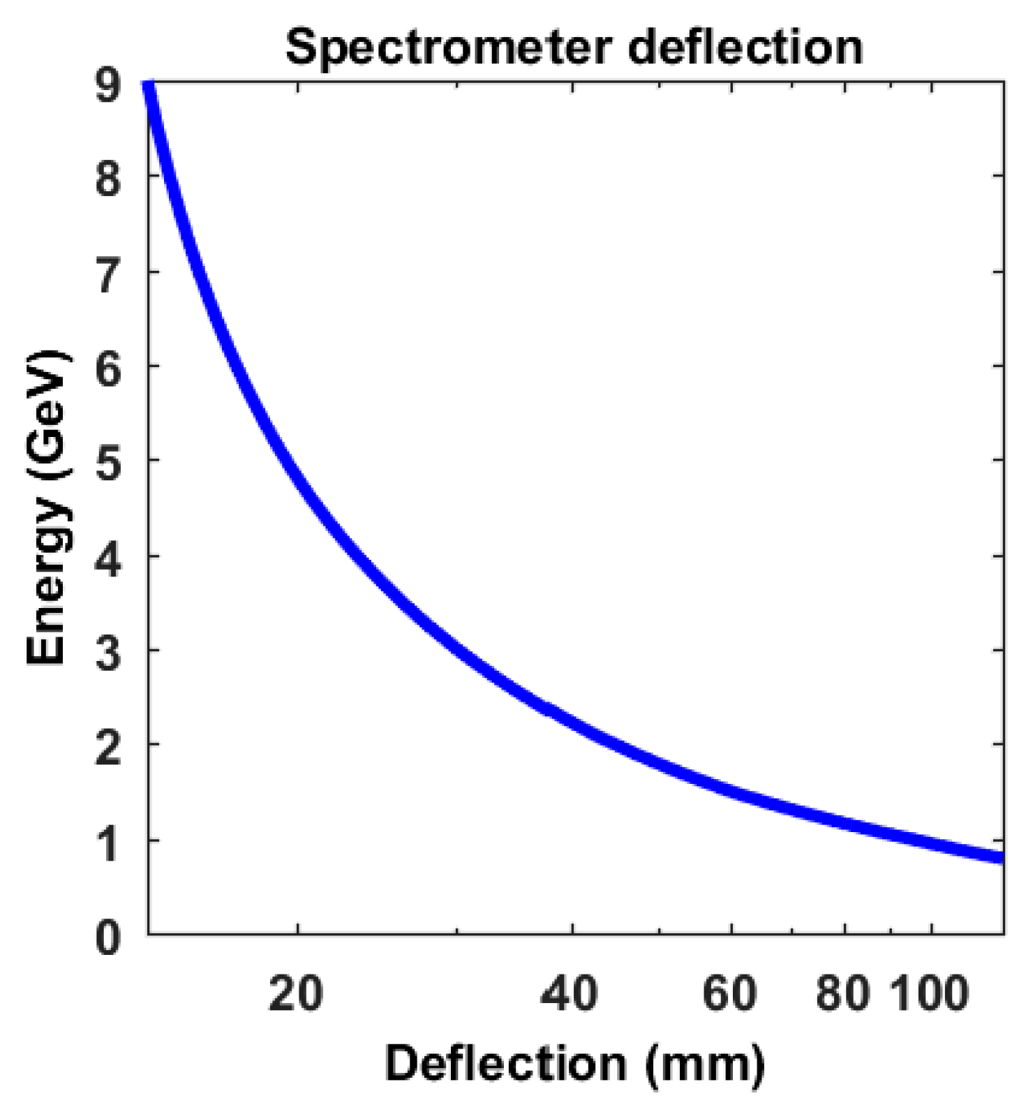
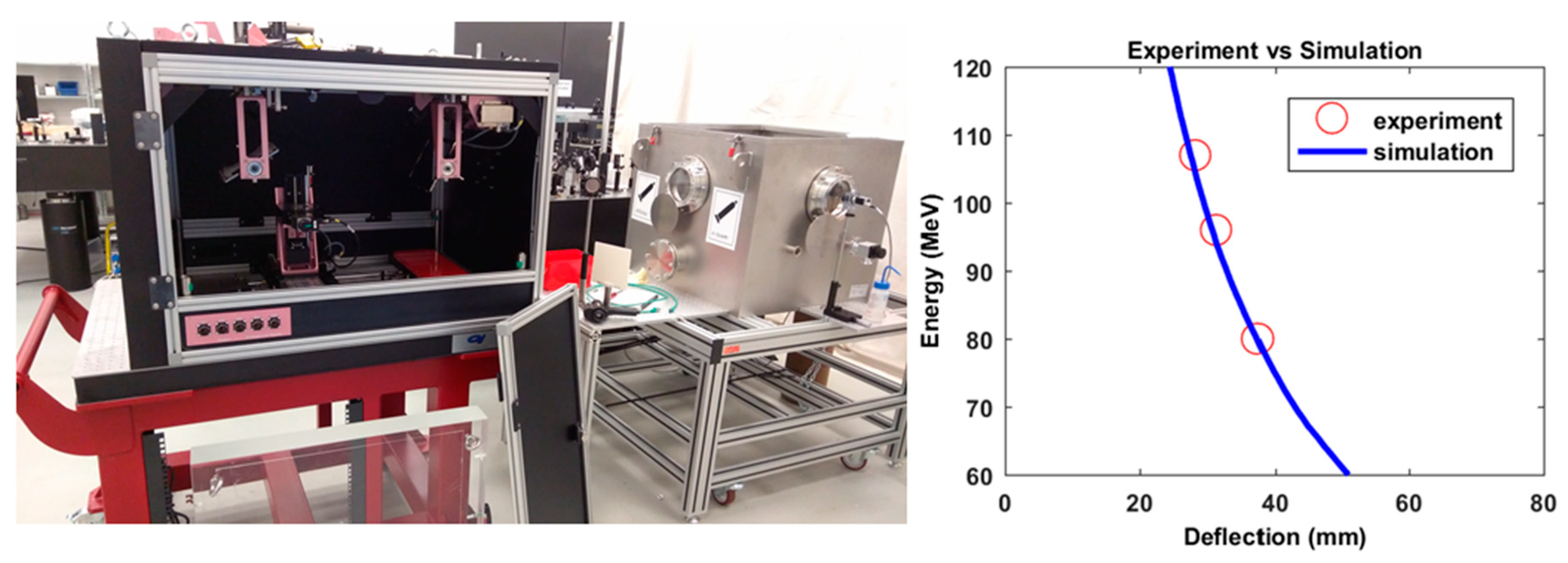
2.4. Diagnostics for Plasma Interaction and Electron Beams

To optimize the laser-plasma interaction, thus the acceleration of electrons, it is important to consider the gas target neutral density profile that determines the generated longitudinal and transverse plasma profile. Moreover, its evolution is important both before and after the main driver pulse. For this, a probe beam is usually used in the direction perpendicular to the driver pulse. In addition to such active probing of the plasma, Thomson scattering emission provides useful information during the interaction by means of optical imaging [40,41]. Such diagnostics can be realized by directly detecting the laser light scattered by the relativistic electron bunch with a CCD or CMOS camera, and also setting up an optical system to resolve the fine details of the laser propagation in the acceleration area around the laser waist position. Since the Thomson scattering pattern is polarization dependent, typically it is observed from a top window in the interaction chamber, i.e., in the direction perpendicular to the p-polarized laser beam plane of incidence.
Figure 18 shows an example of top-view Thomson scattering image from which it is possible to infer the laser beam propagation direction inside the supersonic gas target by identifying the position corresponding to the maximum scattered light intensity. This diagnostics is very useful both in the first stage of a LWFA experiment (or during the warm-up of an electron acceleration beamline as HELL) and in the fine tuning optimization of the electron beam parameters. Indeed, in the first phase, it is used to optimize the plasma interaction by monitoring the laser propagation into the plasma (Thomson scattering) and moving the gas target and/or changing the gas density profile. Since such light scattering is also density dependent, a proper gas-jet density profile measure is very important. This is obtained with simultaneous interferometric measurements. Figure 19 shows the optical setup used for interferometry (left), the longitudinal phase-shift profile (center), the transversal phase-shift profile of a 4 mm by 1 mm gas-jet profile in the case of Argon at 40 bar (right). Figure 20 shows the gas density distribution at three different heights z above the nozzle exit obtained by the multiplicative algebraic reconstruction technique.
The neutral density profile measurement in combination with the Thomson scattering diagnostics are of key importance for the optimization of the propagation of the driver pulse, hence to efficiently accelerate the electron beam. The effect of different gas-density profile on LFWA can be beneficial in particular conditions [42].
Electron beams accelerated in the HELL platform will be characterized in terms of their geometrical properties (charge, divergence, and pointing stability) and energy spectrum (pC MeV−1 msr−1). In order to retrieve this information, a combination of fluorescent screens and magnetic dipoles has been designed and tested. The design of the spectrometer is not trivial, since the expected range of energies at the HELL platform spans over more than three orders of magnitude (MeV-GeV), and a single magnetic dipole cannot cover with sufficient resolution such a wide range of energies. A preliminary set of measurements at a multi-GeV energy range as been performed and will be described in a different manuscript.
According to the state of the art, the highest energy experimentally demonstrated with a PW-class laser is 4.6 GeV [11], the choice for the HELL platform implementation is to design a spectrometer that is capable of resolving with good resolution energies up to at least 10 GeV. In order to meet these requirements a series of different magnetic dipoles has been designed [43,44]. Each dipole is mounted on a linear stage, and by their combination, it is possible to achieve the highest spectral resolution at the energy of interest. The modular configuration, in which different modules can be additionally used for a specific energy range, is shown in Figure 21. A 0.5 to 10 GeV case is analyzed. The electron beam enters the series of dipoles from the right side of the image. First, the electron beam is cleaned from its low energy component up to 6 MeV by the first small dipoles, which deflect the low energy on a dedicated local shielding, and do not affect the electrons above 100 MeV. After that, a H-shaped-magnet is used to bend electrons in the energy range of interest into the 80 cm long, 1 T, C-shape dipole. This last is the strongest dipole, the one that allows for high resolution GeV-spectrometry, as shown in Figure 22. The simulation is done in two steps: first the magnetic field is simulated with the Radia Software, then the electrons are propagated in such field with the software Simion. Due to the overall length of the system, and to the typical LWFA beam parameters, each gap has been designed to have the highest acceptance. The minimum gap for each dipole has been designed to be 15 mm, which corresponds to a 12 mrad full angle acceptance of the system. Figure 22 shows the simulated deflection for a pencil beam in the range 1–10 GeV. After designing the electron beam diagnostics, the performance of the low energy range have been characterized with the preinjector electron beam at the synchrotron Elettra [45]. The parameters of the preinjector beam are 100 MeV, 100 pC at 2.6 Hz repetition rate . During the test by varying the beam energy between 80 and 110 MeV, the bending of the 7 cm, 0.8 T magnetic dipole has been tested. The measured values are in very good agreement with the ones that were predicted by the simulations, as shown in Figure 23 (right). The spectrometer resolution over the entire energy range will be described in future work.
Being the HELL platform partly devoted to multi-disciplinary experiments, the first end station of a laser plasma electron accelerator has been realized. It has been designed and built by Elettra, according to the specifications that are provided by ELI-Beamlines. A picture of the station is shown in Figure 23 (left). The overall size of the User Station fits in a 1 m side square. The scope of the User Station is twofold: (i) to position with an accuracy of at least 10 µm a user samples, and (ii) to characterize shot-to-shot the beam which hits the sample. Thanks to this system, the user sample can be scanned in XYZ and rotated of 2π around the vertical axis. The maximum weight allowed for the sample is 5 kg. The electron beam is characterized on-line by two movable fluorescent screens; one placed before the target and one after it. Finally, the User Station has been designed to be compatible with the HELL beamline and with the ELI-Beamlines control system, in order to provide to the Users an integrated set of data compatible with the other facility diagnostics devices.

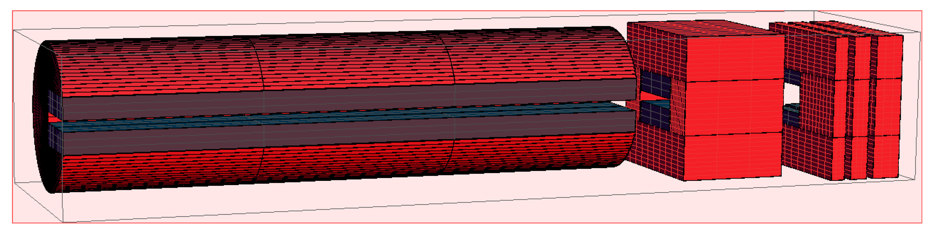
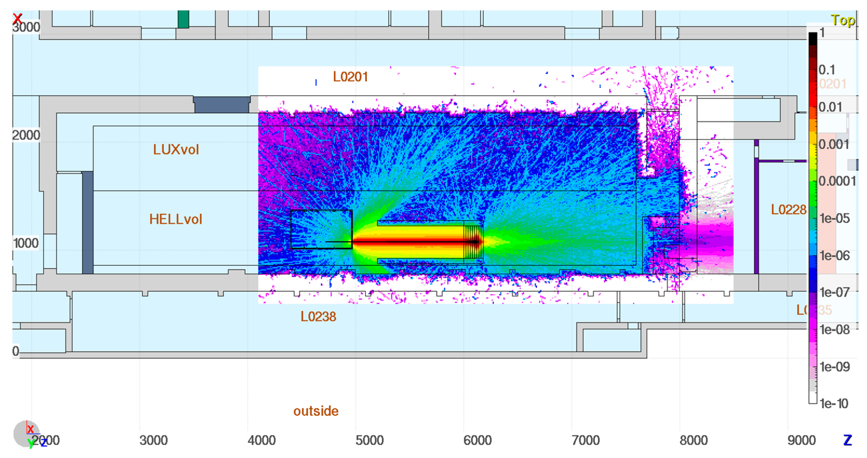
2.5. Radioprotection Analysis and Shielding Design

The electron beams produced by HELL will generate mixed radiation high energy fields, whose strength will increase with the beam energy. Given the aim to accelerate electrons in the GeV range, an adequate assessment of the ionizing radiation hazard is necessary. The studies were performed by means of simulations using the FLUKA Monte Carlo transport code [46,47,48], for a conservative worst-case scenario from the radioprotection point of view. Specifically, for a monochromatic 10 GeV electron beam with a conservative 100pC pulse-charge, 10 mrad divergence, and single shot operation mode. Civil structure of the experimental building was designed in such a way that the shielding provided by the walls, together with a suitable beam dump, allows for operations of electron beams of tens of GeV, while keeping the dose rate in the highly occupied areas, such as control rooms, below 1 mSv per year (which is the legal limit for exposure of general public).
Several factors have to be taken into account for the beam dump shielding design: the possible presence of a magnet to bend the electron beam (as in reality the beam will not be monochromatic); the need for the shielding to be modular in order to scale with the experimental modifications and improvements (e.g., beam energy and charge); the need to allocate sufficient space downstream the beam to allow for the installation of additional experimental equipment; the need to minimize the backscattering toward the experimental chamber; and, the presence of another beamline in the same experimental hall. All of these considerations lead to the preliminary design of the shielding shown in Figure 24. The preliminary shielding design is symmetric with respect to the beam height (1.3 m from the ground). The core of the shielding, designed to be hit at its centre by the electron beam, is located 10 m from the experimental chamber and is flanked by two long lateral “legs”. The shielding core (3 m × 1 m, w × h) is made of five layers of polyethylene, two layers of iron, and two layers of concrete, each layer being 20 cm thick. The core is lying over concrete foundations of the same horizontal dimensions. The electron beam will be stopped mainly by the iron, the concrete behind will absorb the attenuated radiation, while the polyethylene will reduce the backscattering. The two lateral legs are 10 m long and 0.5 m wide. One shields the other beamline, while the second shields the beam deflected by the spectrometer and protects walls from possible long term irradiation damage. Figure 25 shows the ambient dose equivalent rate results that were obtained from the Monte Carlo simulations, where it is apparent that between the two shielding legs only few shots would lead to integrating a personal dose of 1 mSv. Currently, modifications to the shielding design and experimental setup are being investigated [49]. First, adding a thin window to the chamber wall that was hit by the electron beam. While the beam is generated with a small divergence, its interaction with the downstream experimental chamber panel (2 cm thick aluminium) produces a widespread radiation. Instead, thin window would effectively reduce the beam scattering. Other modifications under investigation include the presence of a spectrometer in the beam and the reduction of the radiation escaping the back of the shielding. Another future research option is to exploit muons present in this escaping radiation for obtaining “non-collimated muon beam” that could be used for the testing of muon detectors for high energy physics. The highly penetrating radiation visible in Figure 25 (i.e., the zones in tones of magenta on the right end of the picture) indicate large muon production in the dump already at the considered energy.

3. Conclusions

A general overview of the “HELL platform project” have been given with a first description of the main instrumentations and capabilities that will be available to the scientific community. The concept of experimental platform is flexible to allow for additional experimental schemes not shown in this manuscript.

Acknowledgments

This work has been supported by the project ELI—Extreme Light Infrastructure—phase 2 (CZ.02.1.01/ 0.0/0.0/15_008/0000162) from European Regional Development Fund, by the Ministry of Education, Youth and Sports of the Czech Republic (project No. LQ1606), and by the project “advanced research using high intensity laser produced photons and particles” (CZ.02.1.01/0.0/0.0/16_019/0000789) from European Regional Development Fund. We acknowledge support from the project High Field Initiative (CZ.02.1.01/0.0/0.0/15_003/0000449) from the European Regional Development Fund.

Conflicts of Interest

The authors declare no conflicts of interest.

References

  1. Tajima, T.; Dawson, J.M. Laser electron accelerator. Phys. Rev. Lett. 1979, 43, 267. [Google Scholar] [CrossRef]
  2. Mourou, G.A.; Korn, G.; Sandner, W.; Collier, J.L. ELI—Extreme Light Infrastructure Whitebook, Science and Technology with Ultra-Intense Lasers; THOSS Media GmbH: Berlin, Germany, 2011. [Google Scholar]
  3. The ELI Beamline Project Website. Available online: https://www.eli-beams.eu/ (accessed on 29 August 2018).
  4. Rus, B.; Bakule, P.; Kramer, D.; Naylon, J.; Thoma, J.; Fibrich, M.; Green, J.T.; Lagron, J.C.; Antipenkov, R.; Bartoníček, J.; et al. ELI-beamlines: Progress in development of next generation short-pulse laser systems. In Proceedings of the SPIE 10241, Research Using Extreme Light: Entering New Frontiers with Petawatt-Class Lasers III, Prague, Czech Republic, 24–27 April 2017. [Google Scholar]
  5. HELL platform project. Available online: https://www.eli-beams.eu/en/facility/experimental-halls/e5-electron-accelaration-laser-undulator-x-ray-source/hell-experiment/ (accessed on 4 September 2018).
  6. Geddes, C.G.; Toth, C.; Van Tilborg, J.; Esarey, E.; Schroeder, C.B.; Bruhwiler, D.; Nieter, C.; Cary, J.; Leemans, W.P. High-quality electron beams from a laser wakefield accelerator using plasma-channel guiding. Nature 2004, 431, 538. [Google Scholar] [CrossRef] [PubMed]
  7. Mangles, S.P.; Murphy, C.D.; Najmudin, Z.; Thomas, A.G.; Collier, J.L.; Dangor, A.E.; Divall, E.J.; Foster, P.S.; Gallacher, J.G.; Hooker, C.J.; et al. Monoenergetic beams of relativistic electrons from intense laser–plasma interactions. Nature 2004, 431, 535. [Google Scholar] [CrossRef] [PubMed]
  8. Faure, J.; Glinec, Y.; Pukhov, A.; Kiselev, S.; Gordienko, S.; Lefebvre, E.; Rousseau, J.P.; Burgy, F.; Malka, V. A laser-plasma accelerator producing monoenergetic electron beams. Nature 2004, 431, 541. [Google Scholar] [CrossRef] [PubMed]
  9. Leemans, W.P.; Nagler, B.; Gonsalves, A.J.; Toth, C.; Nakamura, K.; Geddes, C.G.; Esarey, E.; Schroeder, C.B.; Hooker, S.M. GeV electron beams from a centimetre-scale accelerator. Nat. Phys. 2006, 2, 696–699. [Google Scholar] [CrossRef]
  10. Wang, X.; Zgadzaj, R.; Fazel, N.; Li, Z.; Yi, S.A.; Zhang, X.; Henderson, W.; Chang, Y.Y.; Korzekwa, R.; Tsai, H.E.; et al. Quasi-monoenergetic laser-plasma acceleration of electrons to 2 GeV. Nat. Commun. 2013, 4, 1988. [Google Scholar] [CrossRef] [PubMed]
  11. Leemans, W.P.; Gonsalves, A.J.; Mao, H.S.; Nakamura, K.; Benedetti, C.; Schroeder, C.B.; Tóth, C.; Daniels, J.; Mittelberger, D.E.; Bulanov, S.S.; et al. Multi-GeV Electron Beams from Capillary-Discharge-Guided Subpetawatt Laser Pulses in the Self-Trapping Regime. Phys. Rev. Lett. 2014, 113, 245002. [Google Scholar] [CrossRef] [PubMed]
  12. HELL Detailed User Workshop. Available online: https://www.eli-beams.eu/en/media/events/hell-dur-2014/ (accessed on 4 September 2018).
  13. Faure, J.; Rechatin, C.; Norlin, A.; Lifschitz, A.; Glinec, Y.; Malka, V. Controlled injection and acceleration of electrons in plasma wakefields by colliding laser pulses. Nature 2006, 444, 737. [Google Scholar] [CrossRef] [PubMed]
  14. Lu, W.; Tzoufras, M.; Joshi, C.; Tsung, F.S.; Mori, W.B.; Vieira, J.; Fonseca, R.A.; Silva, L.O. Generating multi-GeV electron bunches using single stage laser wakefield acceleration in a 3D nonlinear regime. Phys. Rev. Spéc. Top. Accelerators Beams 2007, 10, 061301. [Google Scholar] [CrossRef]
  15. Bulanov, S.V.; Esirkepov, T.Z.; Hayashi, Y.; Kando, M.; Kiriyama, H.; Koga, J.K.; Kondo, K.; Kotaki, H.; Pirozhkov, A.S.; Bulanov, S.S.; et al. On the design of experiments for the study of extreme field limits in the interaction of laser with ultrarelativistic electron beam. Nucl. Instrum. Methods Phys. Res. Sect. A 2011, 660, 31–42. [Google Scholar] [CrossRef] [Green Version]
  16. Arber, T.D.; Bennett, K.; Brady, C.S.; Lawrence-Douglas, A.; Ramsay, M.G.; Sircombe, N.J.; Gillies, P.; Evans, R.G.; Schmitz, H.; Bell, A.R.; et al. Contemporary particle-in-cell approach to laser-plasma modelling. Plasma Phys. Control. Fusion 2015, 57, 113001. [Google Scholar] [CrossRef]
  17. Di Piazza, A.; Müller, C.; Hatsagortsyan, K.Z.; Keitel, C.H. Extremely high-intensity laser interactions with fundamental quantum systems. Rev. Mod. Phys. 2012, 84, 1177. [Google Scholar] [CrossRef]
  18. Silva, L.O.; Fiúza, F.; Fonseca, R.A.; Martins, J.L.; Martins, S.F.; Vieira, J.; Huang, C.; Lu, W.; Tsung, F.; Tzoufras, M.; et al. Laser electron acceleration with 10 PW lasers. C. R. Phys. 2009, 10, 167–175. [Google Scholar] [CrossRef]
  19. Martins, S.F.; Fonseca, R.A.; Lu, W.; Mori, W.B.; Silva, L.O. Exploring laser-wakefield-accelerator regimes for near-term lasers using particle-in-cell simulation in Lorentz-boosted frames. Nat. Phys. 2010, 6, 311–316. [Google Scholar] [CrossRef]
  20. Bulanov, S.V.; Inovenkov, I.N.; Kirsanov, V.I.; Naumova, N.M.; Sakharov, A.S. Ultra fast depletion of ultra-short and relativistically strong laser pulses in an underdense plasma. Phys. Fluids B 1992, 4, 1935. [Google Scholar] [CrossRef]
  21. Pukhov, A.; Meyer-ter-Vehn, J. Laser wake field acceleration: The highly non-linear broken-wave regime. Appl. Phys. B 2002, 74, 355–361. [Google Scholar] [CrossRef]
  22. Lu, W.; Huang, C.; Zhou, M.; Mori, W.B.; Katsouleas, T. Nonlinear Theory for Relativistic Plasma Wakefields in the Blowout Regime. Phys. Rev. Lett. 2006, 96, 165002. [Google Scholar] [CrossRef] [PubMed]
  23. Thomas, A.G.R.; Ridgers, C.P.; Bulanov, S.S.; Griffin, B.J.; Mangles, S.P.D. Strong Radiation-Damping Effects in a Gamma-Ray Source Generated by the Interaction of a High-Intensity Laser with a Wakefield-Accelerated Electron Beam. Phys. Rev. X 2012, 2, 041004. [Google Scholar] [CrossRef]
  24. Cole, J.M.; Behm, K.T.; Gerstmayr, E.; Blackburn, T.G.; Wood, J.C.; Baird, C.D.; Duff, M.J.; Harvey, C.; Ilderton, A.; Joglekar, A.S.; et al. Experimental evidence of radiation reaction in the collision of a high-intensity laser pulse with a laser-wakefield accelerated electron beam. Phys. Rev. X 2018, 8, 011020. [Google Scholar] [CrossRef]
  25. Bulanov, S.V.; Esirkepov, T.; Tajima, T. Light intensification towards the Schwinger limit. Phys. Rev. Lett. 2003, 91, 085001. [Google Scholar] [CrossRef] [PubMed]
  26. Bulanov, S.V.; Esirkepov, T.Z.; Kando, M.; Pirozhkov, A.S.; Rosanov, N.N. Relativistic Mirrors in Plasmas–Novel Results and Perspectives. Phys. Uspekhi 2013, 56, 429–464. [Google Scholar] [CrossRef]
  27. Kando, M.; Esirkepov, T.Z.; Koga, J.K.; Pirozhkov, A.S.; Bulanov, S.V. Coherent, Short X-ray Generation via Relativistic Flying Mirrors. Quantum Beam Sci. 2018, 2, 7. [Google Scholar] [CrossRef]
  28. Ehrlich, Y.; Cohen, C.; Zigler, A.; Krall, J.; Sprangle, P.; Esarey, E. Guiding of High Intensity Laser Pulses in Straight and Curved Plasma Channel Experiments. Phys. Rev. Lett. 1996, 77, 4186. [Google Scholar] [CrossRef] [PubMed]
  29. Hooker, S.M.; Spence, D.J.; Smith, R.A. Guiding of high-intensity picosecond laser pulses in a discharge-ablated capillary waveguide. Opt. Soc. Am. B 2000, 17, 90–98. [Google Scholar] [CrossRef]
  30. Bobrova, N.A.; Esaulov, A.A.; Sakai, J.I.; Sasorov, P.V.; Spence, D.J.; Butler, A.; Hooker, S.M.; Bulanov, S.V. Simulations of a hydrogen-filled capillary discharge waveguide. Phys. Rev. E 2001, 65, 016407. [Google Scholar] [CrossRef] [PubMed]
  31. Sasorov, P.V.; Bobrova, N.A.; Olkhovskaya, O.G.; Bagdasarov, G.A.; Boldarev, A.S.; Gasilov, V.A.; Bulanov, S.S.; Gonsalves, A.J.; Schroeder, C.B.; Esarey, E.; et al. Simulations of Plasma Channel Formation by Knife-Like Nanosecond Laser Beam; KIAM RAS: Moscow, Russia, 2018. [Google Scholar]
  32. Bagdasarov, G.A.; Sasorov, P.V.; Gasilov, V.A.; Boldarev, A.S.; Olkhovskaya, O.G.; Benedetti, C.; Bulanov, S.S.; Gonsalves, A.; Mao, H.S.; Schroeder, C.B.; et al. Laser beam coupling with capillary discharge plasma for laser wakefield acceleration applications. Phys. Plasmas 2017, 24, 083109. [Google Scholar] [CrossRef] [Green Version]
  33. Bagdasarov, G.A.; Bobrova, N.A.; Boldarev, A.S.; Olkhovskaya, O.G.; Sasorov, P.V.; Gasilov, V.A.; Barber, S.K.; Bulanov, S.S.; Gonsalves, A.J.; Schroeder, C.B.; et al. On production and asymmetric focusing of flat electron beams using rectangular capillary discharge plasmas. Phys. Plasmas 2017, 24, 123120. [Google Scholar] [CrossRef] [Green Version]
  34. Bagdasarov, G.; Sasorov, P.; Boldarev, A.; Olkhovskaya, O.; Gasilov, V.; Gonsalves, A.J.; Barber, S.; Bulanov, S.S.; Schroeder, C.B.; van Tilborg, J.; et al. Plasma equilibrium inside various cross-section capillary discharges. Phys. Plasmas 2017, 24, 053111. [Google Scholar] [CrossRef] [Green Version]
  35. Nevrkla, M. Proceedings of the 1st Annual HiLASE Wokrshop.
  36. Gasilov, V.; Boldarev, A.; Dyachenko, S.; Olkhovskaya, O.; Kartasheva, E.; Bagdasarov, G.; Boldyrev, S.; Gasilova, I.; Shmyrov, V.; Tkachenko, S.; et al. Applications, Tools and Techniques on the Road to Exascale Computing, Advances in Parallel Computing; de Bosschere, K., D’Hollander, E.H., Joubert, G.R., Padua, D., Peters, F., Eds.; IOS Press: Amsterdam, The Netherlands, 2012; Volume 22, p. 235. [Google Scholar]
  37. Negro, M.; Quintavalla, M.; Mocci, J.; Ciriolo, A.G.; Devetta, M.; Muradore, R.; Stagira, S.; Vozzi, C.; Bonora, S. High-speed adaptive deformable lens for boosting an high-energy optical parametric amplifier. In Proceedings of the 2017 European Conference on Lasers and Electro-Optics and European Quantum Electronics Conference, Munich, Germany, 25–29 June 2017. [Google Scholar]
  38. Mocci, J.; Quintavalla, M.; Trestino, C.; Bonora, S.; Muradore, R. A multi-platform CPU-based architecture for cost-effective adaptive optics systems. IEEE Trans. Ind. Inform. 2018. [Google Scholar] [CrossRef]
  39. Gu, Y.J.; Klimo, O.; Kumar, D.; Liu, Y.; Singh, S.K.; Esirkepov TZh Bulanov, S.V.; Weber, S.; Korn, G. Fast magnetic-field annihilation in the relativistic collisionless regime driven by two ultrashort high-intensity laser pulses. Phys. Rev. E 2016, 93, 103203. [Google Scholar] [CrossRef] [PubMed]
  40. Gizzi, L.A.; Cecchetti, C.A.; Giulietti, A.; Giulietti, D.; Koester, P.; Labate, L.; Levato, T.; Pathak, N. Thomson Scattering Imaging From Ultrashort Ultraintense Laser Interaction With Gas. IEEE Trans. Plasma Sci. 2011, 39, 2954–2955. [Google Scholar] [CrossRef]
  41. Jaroszynski, D.A.; Bingham, R.A.; Cairns, R.A. Laser Plasma Interactions; CRC Press: Boca Raton, FL, USA, 2009. [Google Scholar]
  42. Guillaume, E.; Döpp, A.; Thaury, C.; Phuoc, K.T.; Lifschitz, A.; Grittani, G.; Goddet, J.-P.; Tafzi, A.; Chou, S.; Veisz, L.; et al. Electron rephasing in a laser-wakefield accelerator. Phys. Rev. Lett. 2015, 115, 155002. [Google Scholar] [CrossRef] [PubMed] [Green Version]
  43. Grittani, G.M.; Levato, T.; Krus, M.; Fasso, A.; Jeong, T.M.; Kim, H.T.; Margarone, D.; Mocek, T.; Precek, M.; Versaci, R.; et al. Design and development of the HELL user station: Beam transport, characterization, and shielding. In Proceedings of the SPIE 9515K, Prague, Czech Republic, 13–16 April 2015. [Google Scholar] [CrossRef]
  44. Grittani, G.M.; Levato, T.; Korn, G. Design and development of the HELL User Station for multi-disciplinary experiments. In Proceedings of the SPIE 102410E, Prague, Czech Republic, 24–27 April 2017. [Google Scholar] [CrossRef]
  45. Synchrotron and free electron laser radiation and their applications in materials and life sciences. Available online: http://www.elettra.eu/ (accessed on 4 September 2018).
  46. Battistoni, G.; Boehlen, T.; Cerutti, F.; Chin, P.W.; Esposito, L.S.; Fassò, A.; Ferrari, A.; Lechner, A.; Empl, A.; Mairani, A.; et al. Overview of the FLUKA code. Ann. Nucl. Energy 2015, 82, 10–18. [Google Scholar] [CrossRef] [Green Version]
  47. Ferrari, A.; Sala, P.R.; Fasso, A.; Ranft, J. FLUKA: A Multi-Particle Transport Code; CERN-2005-10; U.S. Department of Energy: Washington, DC, USA, 2015.
  48. Vlachoudis, V. Flair: A Powerful But User Friendly Graphical Interface for FLUKA. In Proceedings of the International Conference on Mathematics, Computational Methods & Reactor Physics (M&C 2009), Saratoga Springs, NY, USA, 3–7 May 2009. [Google Scholar]
  49. Sasorov, P.V.; Bobrova, N.A.; Olkhovskaya, O.G.; Bagdasarov, G.A.; Boldarev, A.S.; Gasilov, V.A.; Bulanov, S.S.; Gonsalves, A.J.; Schroeder, C.B.; Esarey, E.; et al. Radiation shielding of electron beamlines at ELI Beamlines. In Proceedings of the Shielding aspects of Accelerators, Target and Irradiation Facilities (SATIF-13), Dresden, Germany, 10–12 October 2016. [Google Scholar]
Figure 1. Electron density after 1 mm of propagation in a three-dimensional (3D) Particle In Cell (PIC) simulation of a 0.2 PW, 30 fs pulse focused to a waist of 19.8 um at 1.5 × 10¹⁸ e/cm3.
Applsci 08 01565 g001
Figure 2. Modeling of (left) the L3 laser ideal spatial distribution (right) the L3 spatial distribution with artificial modulations.
Applsci 08 01565 g002
Figure 3. (left) L3 artificially modulated phase-front. (right) Simulation of the deformable mirror corrected phase-front.
Applsci 08 01565 g003
Figure 4. (top) High-energy Electrons by Laser Light (HELL) platform in the E5 experimental hall of ELI-Beamlines. (bottom) Detailed view of the HELL platform showing the auxiliary chamber with the OAP, the DM and leak mirrors; the interaction chamber with the basic driver beam for laser wake field acceleration (LWFA) and the counter-propagating beam is also shown.
Applsci 08 01565 g004
Figure 5. Simulated focal distributions (up) for the 4.4 m off-axis parabola (OAP) and intensity plot (down) in the ideal case (left), in the artificially modulated case (center-red), with the deformable mirror (DM) compensation (right) and (center-blue).
Applsci 08 01565 g005
Figure 6. Simulated focal distributions (up) for the 10 m OAP and intensity plot (down) in the ideal case (left), in the artificially modulated case (center-red), with the DM compensation (right) and (center-blue).
Applsci 08 01565 g006
Figure 7. Simulated far fields of ideal intensity masks—circular (left) and square (center). The left pane shows a far field intensity distribution for the circular and square shaped beams. Although side wings are mitigated for the circular space distribution it is not the case for the square one.
Applsci 08 01565 g007
Figure 8. 3D PIC simulation of electrons self-injection in the side wings of the far field intensity distribution for the square beam. The beam ( FWHM = 15 λ , 30 fs, λ = 0.82   μ m ) propagates in a cylindric plasma channel with the radius of 15 μ m . On axis electron number density is 1019 cm−3, outside the channel the density is four times higher. Beam intensity is 10 20   W / c m 2 .
Applsci 08 01565 g008
Figure 9. Conceptual scheme of apodization for the L3 square beam using with a single aperture.
Applsci 08 01565 g009
Figure 10. Simulated focus distribution in log color scale of the 10 m OAP in the (left-top) “square” case and (left-bottom) “apodized” case, (right) maximum intensity profiles renormalized to the “square” case peak value for the wing-to-peak contrast comparison.
Applsci 08 01565 g010
Figure 11. Upper left: CAD model and picture of the capillary, Lower left: Discharge circuit. Right: Discharge current measurement (CH1—Trigger signal, CH2—current probe 10 A/V, CH4—Electrode voltage).
Applsci 08 01565 g011
Figure 12. Simulated focus of a plano-convex coupled with a cylindrical lens to obtain a knife-like focal distribution. It shows the simulated line-shape (or knife-like) focus of five micron extended for about 5 mm.
Applsci 08 01565 g012
Figure 13. HELL auxiliary chamber with the in-vacumm wave-front-sensor (WFS) laser diagnostics area and the in air optical table.
Applsci 08 01565 g013
Figure 14. “In air” wavefront correction system (not in scale). The orange optical path is the Non Common Path (NCP) between the laser beam and the wavefront sensor beam.
Applsci 08 01565 g014
Figure 15. In vacuum wavefront correction system (not in scale). The orange optical path is the NCP between the laser beam and the wavefront sensor beam.
Applsci 08 01565 g015
Figure 16. (left) large size (300 mm × 300 mm) lens array printed on a thin transparent screen, (right) sub-focus array projected on a diffuser imaged with an optical camera.
Applsci 08 01565 g016
Figure 17. (left) logarithmic cross section of the Point Spread Function of the diffraction limited beam (red) and with the beam shaping (green) with the wavefront reported in the diagram on the (right).
Applsci 08 01565 g017
Figure 18. (left) Example of an experimental top-view image showing the Thomson scattered light within a gas target with near-uniform neutral density in the case of a 300 mJ—40 fs laser beam propagation in Nitrogen. (right) Simulated neutral density profile of gas target at different distances from the nozzle exit.
Applsci 08 01565 g018
Figure 19. (left) optical setup used for interferometry, (center) the measured longitudinal phase-shift profile, (right) the measured transversal phase-shift profile.
Applsci 08 01565 g019
Figure 20. (left) neutral density reconstruction in Argon at 40 bar backing pressure at 0.1 mm from the nozzle, (center) at 1 mm, (right) at 2 mm.
Applsci 08 01565 g020
Figure 21. Modular configuration design of the 10 GeV electron spectrometer.
Applsci 08 01565 g021
Figure 22. Simulated deflection for a pencil beam in the range 1–10 GeV using the softwares Radia for the magnetic field and Simion for the particle tracking.
Applsci 08 01565 g022
Figure 23. (left) 3D view technical design of the HELL User Station, (right) measured and simulated electron deflections for the 5 cm, 0.8 T permanent magnet dipole.
Applsci 08 01565 g023
Figure 24. 3D view cut at beam height of the FLUKA model of the HELL beamline. The experimental chamber and the shielding in its preliminary design are visible.
Applsci 08 01565 g024
Figure 25. Horizontal view at beam height of the ambient dose equivalent rate map obtained with FLUKA simulations. The shielding effect of the dump is clearly visible. The units are mSv per shot. The user station is not considered here.
Applsci 08 01565 g025

