Broadening Bandgap Width of Piezoelectric Metamaterial by Introducing Cavity


1
Jiangsu Key Lab of Remote Measurement and Control, School of Instrument Science and Engineering, Southeast University, Nanjing 210096, Jiangsu, China
2
School of Mechanical Engineering, Xi’an Jiaotong University, Xi’an 710049, Shanxi, China
3
Department of Mechanical Engineering, University of Connecticut, Storrs, CT 06269, USA
*
Author to whom correspondence should be addressed.
Appl. Sci. 2018, 8(9), 1606; https://doi.org/10.3390/app8091606
Submission received: 3 August 2018
/
Revised: 27 August 2018
/
Accepted: 4 September 2018
/
Published: 10 September 2018
(This article belongs to the Special Issue Acoustic Metamaterials)
Abstract
:In this research, a semi-analytical model of the adaptive piezoelectric metamaterial, built upon continuum mechanics characterization, was formulated and analyzed to reveal the fundamental features of bandgap with respect to unit-cell parameters under transverse wave. A new mechanism to broaden the bandgap width, was then introduced through geometric cavity synthesis. It was demonstrated that the cavities incorporated into the host structure of the piezoelectric metamaterial can increase the electro-mechanical coupling of the system, which effectively yields broadened bandgap width. Case studies were performed to demonstrate the enhanced performance of the new design, as well as the tunability. Compared with the conventional piezoelectric metamaterial, the metamaterial with cavity synthesis can increase the bandgap width from 45 Hz to 126.7 Hz.
1. Introduction
Metamaterials, defined as artificial structures that exhibit physical properties not available in natural material, have extraordinary capability in low-frequency sound/vibration attenuation, negative refraction, and super lenses [1,2,3,4,5,6,7,8]. The acoustic metamaterials, consisting of periodically arranged unit-cells, are capable of manipulating elastic wave propagation. An acoustic metamaterial may utilize Bragg scattering or local resonance [9,10,11,12,13,14]. Bragg bandgaps stand for the zones between incident and reflected waves, which are generated at wavelengths comparable to the spatial scale of a unit-cell [15,16,17]. Different from the Bragg scattering mechanism, the local resonance mechanism utilizes the sub-wavelength local resonances induced within a unit-cell. The local resonance can alter the frequency-dependent effective mass densities, and/or bulk moduli of the continuum media. In most cases, the internal resonators have highly contrasting elastic properties. Within the bandgap, the elastic wave cannot propagate, and wave energy is reflected back or temporarily stored in resonators [1,18,19].
Owing to their two-way electro-mechanical coupling, piezoelectric transducers have been adopted to induce or enhance bandgap behavior in metamaterials [8,20,21,22]. Piezoelectric metamaterial with periodic resonant circuits can directly produce the local resonance bandgap. This is because a local resonance is created by the LC (inductor-capacitor) circuit, as the piezoelectric transducer acts electrically as a capacitor. For example, piezoelectric periodic arrays are integrated into rods for wave attenuation and localization [20]. In another example, multi-resonant shunts were adopted to generate multiple bandgaps in a piezoelectric metamaterial [21]. Theoretical and experimental investigations on photonic rods and beams [23] with shunt circuits have been performed. Recently, piezoelectric metamaterials were applied in two-dimensional wave steering [24] and vibration mode customization [25]. Notably, piezoelectric metamaterial has advantages over the more conventional mechanical metamaterial in two aspects: Relatively simple configuration and adaptivity. Piezoelectric transducers are usually attached to the host structure directly, and even simple topology/geometry can yield complex dynamic phenomena locally at the unit-cell level, and globally at the metamaterial level. Moreover, the shunted piezoelectric transducers allow the online tuning of bandgap towards a desired frequency range, as one can conveniently integrate tunable circuitry elements.
So far, almost all the studies on piezoelectric metamaterial are based on transfer-matrix method or finite element analysis [22,26]. However, previous investigations concerning piezoelectric shunt design and analysis in sensing/control applications, often resort to the lumped-parameter approach, which can help in revealing the underlying physics with parametric influences [27,28,29]. It is worth noting that circuitry dynamics in the electrical domain is described naturally by the lumped-parameter model. The lumped-parameter approach is suitable for dealing with complex circuitry integration schemes, as well as systems with nonlinearity [30,31]. A more common approach is to conduct continuum mechanics-based modeling of the host substrate, followed by discretization with respect to wavenumber, where an equivalent frequency-dependent Young’s modulus is used to reflect the piezoelectric shunt circuit effect [22,26]. The shunt circuit effect is included as equivalent impedance added to the original mechanical impedance of the transducer. However, such an approach may not be able to deal with complex circuitry, especially those with multiple branches or nonlinear elements.
From the fundamental physics standpoint, one well-known limitation of piezoelectric metamaterial is the relatively narrow bandwidth, compared with other types of acoustic metamaterials. For example, Parra et al. demonstrated numerically and experimentally that the piezoelectric metamaterial has bandgap width of 500 Hz around 5000 Hz [32]. On the other hand, the mass-in-mass metamaterial with mechanical resonance, has bandgap width of up to 5.6 kHz around the frequency of 24.8 kHz [33]. Therefore, the goal of this research is two-fold. Firstly, the lumped-parameter model of the piezoelectric metamaterial is established, which is built upon the continuum mechanics characterization of the host substrate and piezoelectric transducer at the unit-cell level, to reveal the parametric influence on bandgap width. Transverse wave is considered throughout the modeling and analysis, and the lumped parameters are derived based on the wavenumber involved. Secondly, a new and effective design is introduced, based on incorporating geometric cavities in the host structure, to increase the electro-mechanical coupling of the piezoelectric metamaterial. The increased electro-mechanical coupling yields significantly broadened bandgap width. Systematic case investigations through finite element analysis are conducted to demonstrate the modeling and new design.
2. Lumped-Parameter Modeling of Piezoelectric Metamaterial
In this section, a semi-analytical investigation of one-dimensional piezoelectric metamaterial integrated with LC shunt circuits is formulated. Firstly, the configuration of the unit-cell is described, followed by energy analysis based on continuum mechanics characterization. A lumped-parameter model of the piezoelectric metamaterial is formulated by incorporating the periodic boundary condition of the unit-cell, where a representative circuitry configuration, i.e., parallel-connections of the piezoelectric transducers, is considered. The dispersion relations of the piezoelectric metamaterial are then established.
2.1. Configuration of Conventional Piezoelectric Metamaterial
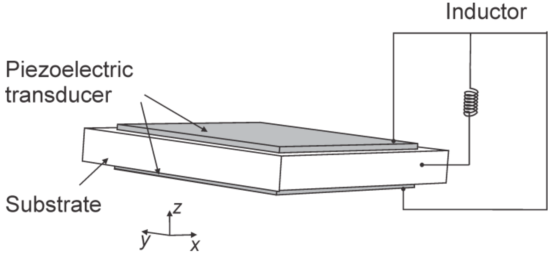
The configuration of the unit-cell of piezoelectric metamaterial is shown in Figure 1. The unit-cell consists of an aluminum substrate and two piezoelectric transducers bonded onto the top and bottom surfaces of the substrate. Inductance element is connected to the top and bottom surfaces of the piezoelectric transducer as the shunt circuit. Note that a piezoelectric transducer acts electrically as a capacitor. The combination of the piezoelectric capacitance and the inductive shunt, creates an LC resonant unit. Moreover, since the piezoelectric transducer possesses two-way electro-mechanical coupling, the local resonance in the electrical domain can affect the system dynamics in the mechanical domain. As such, the LC resonance of the shunt circuit creates bandgap for the integrated system.
2.2. Semi-Analytical Model of Unit-Cell
In this section, Euler-Bernoulli beam theory is used as the basis to analyze the integrated system. The behavior of the metamaterial can be assessed through analyzing the dynamics of a unit-cell. For each unit-cell, a perfect bonding condition between the piezoelectric transducers and the substrate is assumed. Let l, b, h, and denote, respectively, the length, width, thickness, and mass density. Throughout this research, subscripts ‘b’ and ‘p’ are employed to indicate variables related to the host beam substrate and the piezoelectric transducer, respectively. The modeling starts from the extended Hamilton’s principle,
where T is the kinetic energy, U is the potential energy, and is the virtual work.
For the unit-cell, the kinetic energy is
where is the displacement of the transverse wave. The directions of the coordinate system are shown in Figure 1, and the origin is located at the center of the unit-cell being analyzed. The variation of the kinetic energy, takes the form
where and are, respectively, the cross-sectional area of the host beam substrate and that of one piezoelectric transducer. The linear constitutive relation of the piezoelectric transducer is [34].
where , , D, and E represent, respectively, the stress, stain, electrical displacement (charge/area), and electrical field (voltage/length) of the piezoelectric transducer, and , , and are the Young’s modulus at constant electrical displacement, the piezoelectric constant, and the dielectric constant of the transducer at constant strain. Let denote the Young’s modulus of the host beam substrate. The elastic energy of the unit-cell comes from the host substrate and the two transducers, and the electrical energy comes from the two transducers. The variation of the elastic and electrical energies can be derived as
where and represent, respectively, the second moment of inertia of the substrate and that of one piezoelectric transducer, and represents the first moment of area of each transducer.
Using the variation principle and setting the initial conditions as , one can derive
where is the Heaviside function. As the length and width of the piezoelectric transducer may be smaller than those of the host beam substrate, terms associated with the piezoelectric transducer are multiplied by hereafter. The variation of the virtual work done by forces from adjacent unit-cells (applied at the boundaries), can be expressed as [35].
Substituting Equations (6)–(8) into Equation (1), the partial differential equations that govern the motion of the unit-cell, coupled with the piezoelectric transducers are obtained,
where is the virtual work per unit length of the substrate/transducer, due to the mechanical damping. In Equation (9b), the effect of the shunt circuit, i.e., the inductive load, is included as virtual work done to the unit-cell. Let , represent such virtual work per unit length of the transducer. The actual virtual work done by the shunt circuit thus is .
To analyze the dynamic behavior of the piezoelectric metamaterial, one unit-cell is considered, where the Bloch-Floquet theory is employed. Specifically, the mechanical displacement and the electrical displacement are both assumed to have the following representations [36,37],
where is the wavenumber of the transverse wave involved, is its frequency, and are, respectively, the amplitudes of mechanical and electrical displacements. Furthermore, let and denote, respectively, the electrical displacements of the top and bottom transducers. Essentially, these displacement representations reflect that the wave propagates in the piezoelectric metamaterial that is spatially periodic. Our goal here is to develop a lumped-parameter model of the unit-cell, which can be used to elucidate the underlying physics of the piezoelectric metamaterial. Consider an arbitrary wavenumber . Equation (10a,b) are substituted into Equation (9a,b), which are further integrated over the cell length . After some manipulations (please see Appendix A for details), the governing equations of the unit-cell are obtained as
where m is the mass, k is the stiffness, c is the damping coefficient, is the mechanical displacement, i.e., , and are the charges on the transducers on the top and bottom of the substrate, respectively, i.e., and , C is the capacitance of one piezoelectric transducer, is the electro-mechanical parameter between a transducer and the host beam substrate. Specifically,
It is worth noting that, in the unit-cell, two piezoelectric transducers are employed as a bimorph. The top and bottom piezoelectric transducers are identical, and thus have the same capacitance value. The charges, and , and the voltages across the transducers, and , are related to the specific connection configurations, and will be explained subsequently. More importantly, the equivalent mass, stiffness, and electro-mechanical constant are expressed as explicit functions of wavenumber and geometry/material properties. Indeed, in this piezoelectric metamaterial, wave propagates along the continuous beam substrate. The wavenumber indicates the number of waveform cycles per unit length, which decides the corresponding local beam deformation and strain/stress distributions within the unit-cell. Therefore, the equivalent mass, stiffness, and electro-mechanical constant are all wavenumber-dependent.
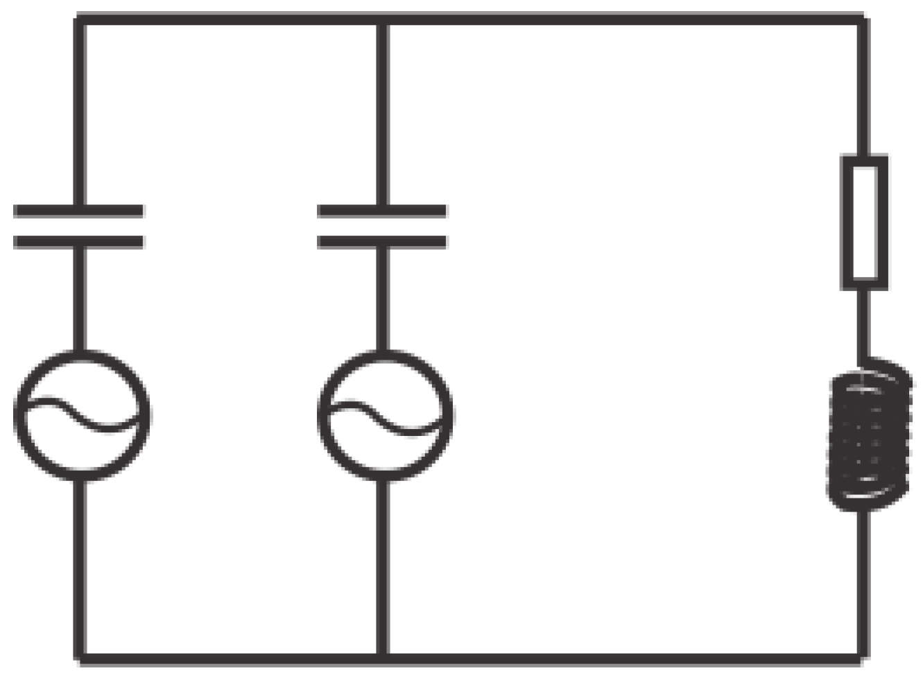
The effect of the circuitry dynamics to unit-cell behavior, where the transducers are connected to inductive shunt in the parallel manner, is now investigated. To derive the governing equations of the integrated system, the electrical dynamics of the unit-cell is examined first. Figure 2 illustrates the equivalent circuit model. The electrodes bracketing the piezoelectric transducers cover fully, the top and the bottom surfaces of each transducer. The electrode layers are connected to an inductive circuit/load. Here the piezoelectric transducers are equated to voltage sources in the equivalent circuit model [28]. A piezoelectric transducer generates electrical displacement due to the mechanical strain, thereby acting as a voltage source. The only cause of mechanical strain is assumed to be the axial strain due to bending wave. The governing equations of a unit-cell integrated with transducers connected with the inductive shunt in the parallel manner, can be written as
where is the inductance value adopted under the parallel-connection configuration, and R is the inherent resistance in the circuitry elements. In this parallel-connection, as the piezoelectric transducers attached to the top and bottom surfaces of the host substrate are identical, the instantaneous charges on the two transducers are equal, i.e., . To evaluate the unit-cell dynamic characteristics, harmonic responses are assumed with frequency , i.e., , , and , where , , and are the phases. For a two-DOF (degree-of-freedom) unit-cell, governed by Equation (13a,b), the dispersion equation under the undamped condition can be derived as
The resonant frequency of the original unit-cell (before the circuitry is integrated) and that of the LC shunt with parallel connected transducers are denoted as, respectively,
Meanwhile, based on the equations of motion (Equation (13a,b)), which characterize the dynamic interaction between the host structure and the piezoelectric transducers, an important parameter, the non-dimensional system-level electro-mechanical coupling coefficient [28], is identified as
As indicated in several previous studies concerning piezoelectric transducer-based sensing and control, this system-level electro-mechanical coupling coefficient reflects quantitatively, the two-way energy conversion between the mechanical and electrical domains [29]. Larger indicates stronger electro-mechanical coupling, and therefore more effective energy conversion between the mechanical and the electrical domains through the transducers.
2.3. Piezoelectric Metamaterial with Cavity
First, the role of the electro-mechanical coupling coefficient in the context of piezoelectric metamaterial, warrants further discussion here. Apparently, according to Equation (16), this non-dimensional coupling coefficient is primarily related to the transducer material property, , i.e., the piezoelectric coupling constant at the material-level. It is also related to the piezoelectric capacitance, the Young’s moduli, the geometry of the substrate and the transducers, and the wavenumber involved. It can be increased with the integration of a negative capacitance element or negative stiffness effect [28]. These indicate that there is potential to increase the system-level electro-mechanical coupling through, either unit-cell material/geometry tailoring and/or circuit design. In this research, the material properties of the transducer and the host structure are kept unchanged. The circuit configuration also remains unchanged. In conventional piezoelectric metamaterial, a significant portion of the energy of the acoustic wave is stored in the mechanical stiffness of the structure, including both the host structure and the piezoelectric transducers, and is not converted into electrical energy due to the limited electro-mechanical coupling coefficient. Subsequently, only a small portion of acoustic wave energy can be transferred into electrical energy, which creates reactive force to affect the wave propagation. As a result, the wave manipulation capability of the system is very limited, reflected by the relatively narrow width of the bandgap.
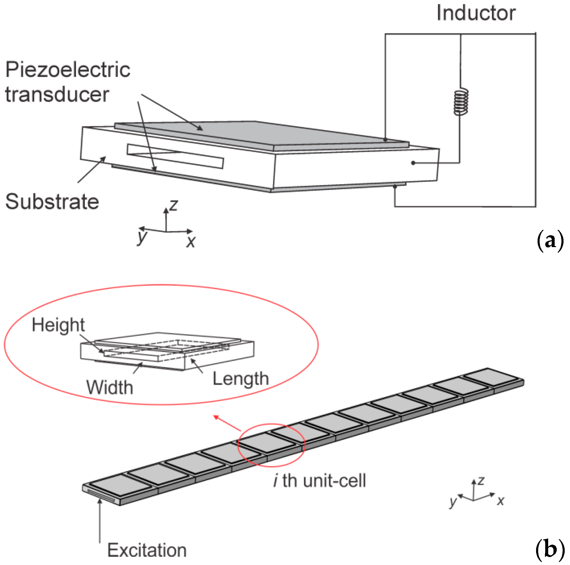
Based on the fundamental modeling and the abovementioned qualitative analysis, in this research, the design enhancement of piezoelectric metamaterial by geometry tailoring is explored. Specifically, it is proposed to introduce a cavity in the host structure substrate of each unit-cell, as shown in Figure 3a,b. Our hypothesis is that the cavity can effectively reduce the unit-cell stiffness, and hence increase the portion of energy that is converted into electrical energy through the piezoelectric effect when the substrate is subjected to wave motion. Consequently, the reactive force from LC resonance would be increased, and the wave attenuation effect and the bandgap width would be enhanced. In such a case, the lumped parameter mass and stiffness of the unit-cell system are modified as:
where , , and are the height, width, and length of the cavity introduced, respectively, and represents the moment of inertia of the cavity volume.
With the introduction of the cavity, the resonant frequency of the unit-cell (before the circuitry is integrated), then becomes
The system-level electro-mechanical coupling with substrate cavity takes the form
The dispersion equation can be re-written as
Recall that the local LC resonant frequency () is usually much smaller than the Bragg scattering frequencies. From Equation (20) it can be observed that, fundamentally, the dispersion relation is decided by both the circuit resonant frequency and the system level electro-mechanical coupling coefficient. The solutions to the dispersion equation under the parallel-connection configuration, can be easily obtained as
Consider that the frequency of LC resonance is a chosen value to fit specific design requirements. The bandgap width of the piezoelectric metamaterial fundamentally hinges upon the term in Equation (21). Choosing piezoelectric transducers with a larger coupling constant , e.g., piezoelectric single crystal (e.g., PMN-PT), may certainly help in the improvement of bandgap characteristics, but this type of material costs much more than piezoelectric ceramic. Many studies employ a negative capacitance element integrated to the piezoelectric transducer, to reduce the equivalent local stiffness of a unit-cell [38], thereby tuning the location of bandgap or influencing its bandwidth. Introducing a cavity in the substrate can mechanically reduce the stiffness of the unit-cell and broaden the bandgap width of the metamaterial, as qualitatively indicated in Equation (21). It should be noted that in practice the cavity geometry does not have to be rectangular in shape. In fact, owing to the rapid advancement of additive manufacturing technology, in future one may create complex shapes of cavity to fit the specific applications, and even perform topology/shape optimization.
3. Case Analyses and Discussions
In this section, systematic parametric analyses of the piezoelectric metamaterial are presented using the semi-analytical equations derived and finite element simulations. All propagating wave modes in lattice/periodic structures can be captured by restricting the dimensionless wavenumber to the first Brillouin zone due to the periodicity. Thus, the dispersion curves are plotted based on wavenumbers within this zone. COMSOL Multiphysics 5.3 is adopted, which is widely used in multi-field coupled investigation and piezoelectric metamaterial analysis, to analyze the dispersion relation and the forced frequency responses of the piezoelectric metamaterial.
The unit-cell is made of aluminum substrate ( mm3) and two piezoelectric ceramic transducers ( mm3) bonded onto the center of the top and bottom surfaces of the substrate. Inductance element is connected to the top and bottom surfaces of the piezoelectric transducer, as the shunt circuit. The conventional unit-cell of piezoelectric metamaterial has a solid substrate. In this research, a through-hole cavity is incorporated underneath the substrate of the unit-cell (Figure 3a). The material parameters are chosen as: piezoelectric mass density = 7500 , piezoelectric Young’s modulus = 65 , piezoelectric constant = −320 , dielectric constant = 2.98 × 10⁸ , host medium mass density , and host medium Young’s modulus . Without loss of generality, the inductance load for unit-cells is given as H to generate a bandgap around 3250 Hz. In practice, the value of inductance load can be arbitrarily modified for the creation of bandgap at other frequencies.
3.1. Dispersion Analysis of Unit-Cell with Cavity
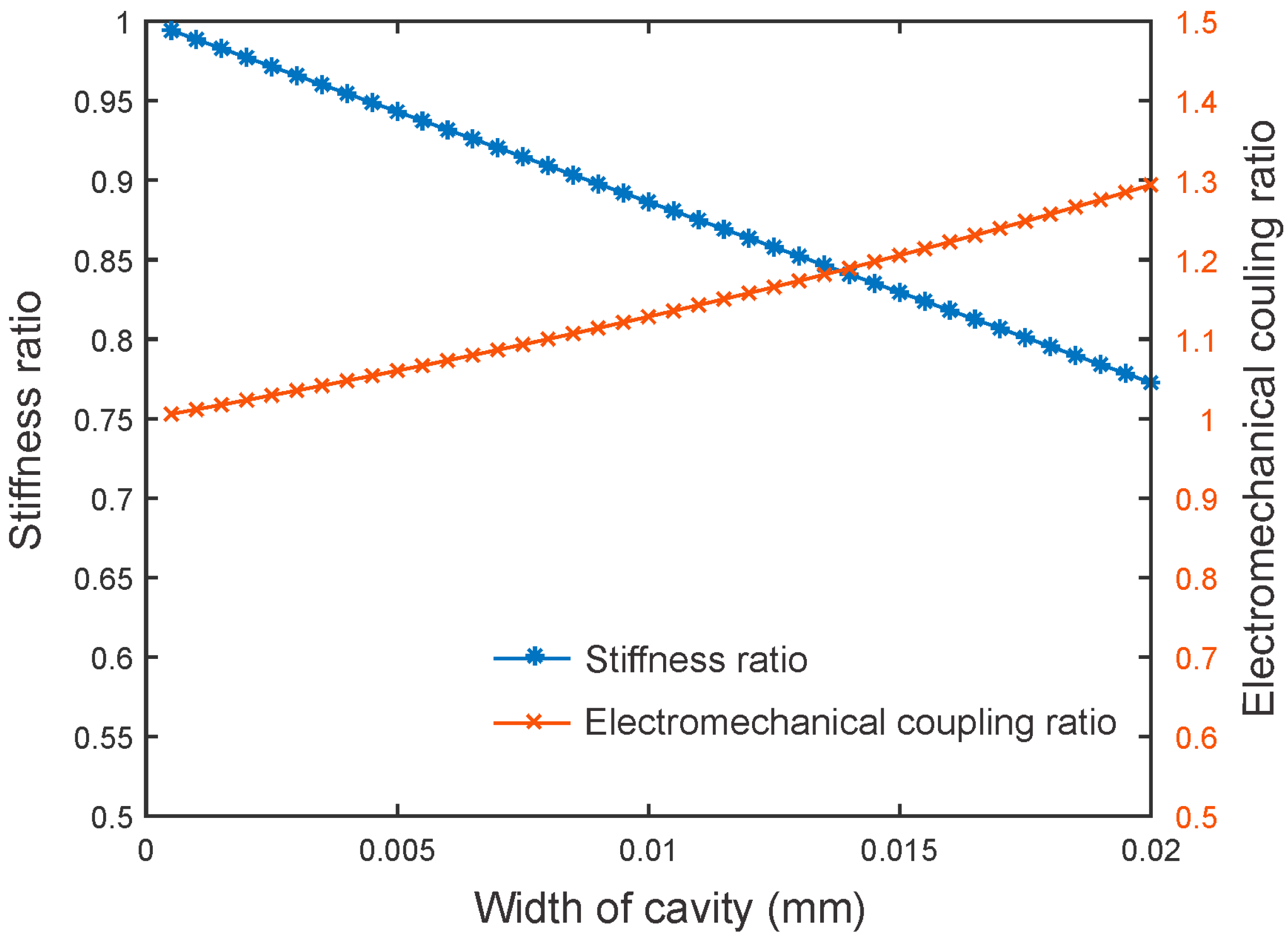
The dispersion relation is studied first, with emphasis on cavity effect. The cavity influences the unit-cell level stiffness and electro-mechanical coupling coefficient. Without loss of generality, a cavity with constant height of 1 mm and length of 25.38 mm is introduced into the center of the substrate. The width is considered as a variable. The theoretical stiffness ratio (the ratio of the stiffness of unit-cell with cavity to that of unit-cell without cavity) and the electro-mechanical coupling coefficient ratio (the ratio of the electro-mechanical coupling coefficient of unit-cell with cavity to that of unit-cell without cavity) with respect to the cavity width, are presented in Figure 4. It can be readily observed that increasing the width of the cavity can effectively reduce the stiffness of the unit-cell, which then yields a significant increase of the system level electro-mechanical coupling. As indicated in Section 2.3, one key parameter for piezoelectric metamaterial is the system-level electro-mechanical coupling coefficient, and the increase of this coupling would yield the improvement of bandgap behavior. It is still worth mentioning that the stiffness reduction implies a trade-off, with respect to load carrying capability of the substrate. Therefore, proper selection of the dimension of the cavity is required in practical applications.
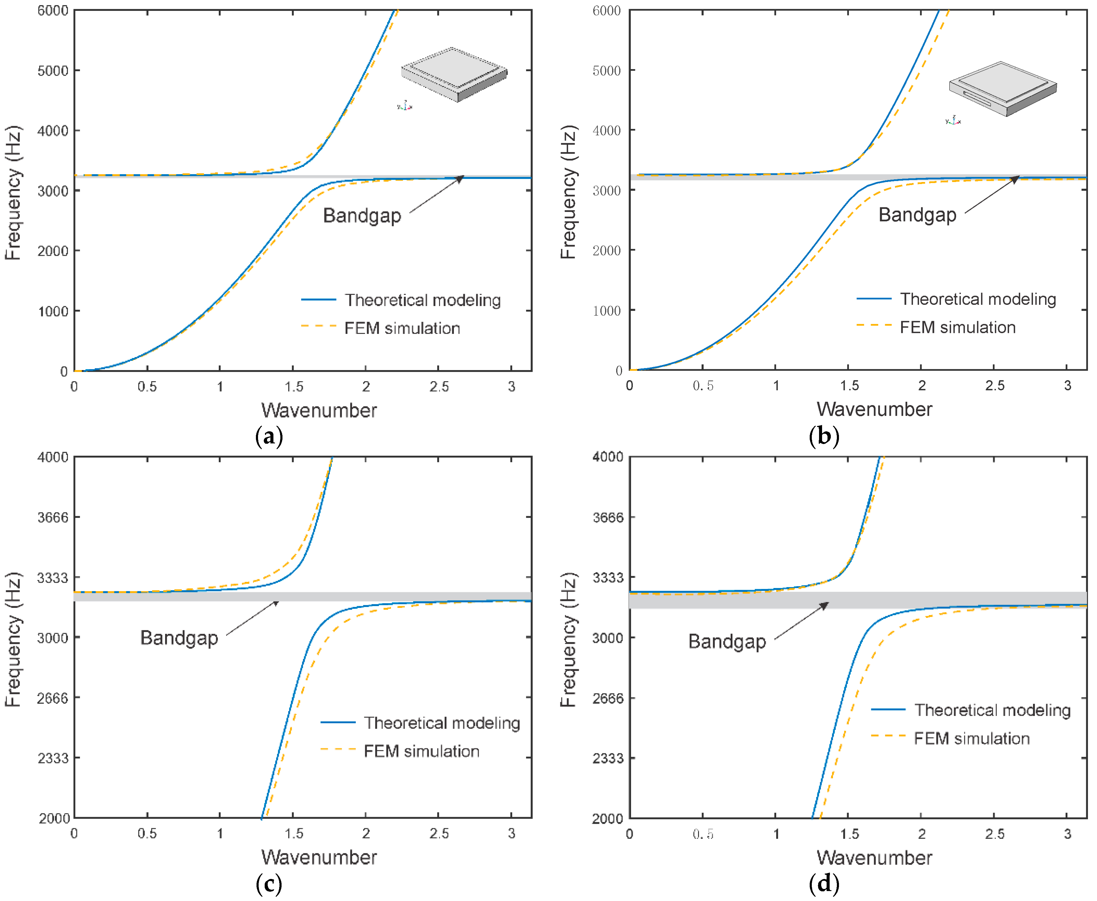
The dispersion curves of the unit-cells, with and without cavity, are then plotted for comparison. One representative example is shown in Figure 5, where a cavity of mm3 is incorporated. These curves are plotted within the first Brillouin zone (), since all propagating wave modes in periodic structures can be captured by restricting the dimensionless wavenumber to this zone, due to the periodicity. Finite element analysis is performed for validation. It can be observed that the integration of the LC shunt circuit in the original, conventional unit-cell, creates a bandgap with a range between 3229 Hz and 3274 Hz. This yields the bandgap width of 45 Hz. In comparison, the one with cavity integration has a bandgap width of 67 Hz (from 3202 to 3269 Hz). The theoretical bandgap widths are 48 Hz and 61 Hz, respectively, for the conventional piezoelectric metamaterial beam and the metamaterial beam with cavity. The percentages of deviation are 6.7% and 9.8%, respectively. The deviation stems from the fact that the finite element simulation is performed in the usual three-dimensional space, and yields more detailed displacement distribution. Fundamentally, as wave propagates through the piezoelectric metamaterial, each unit-cell experiences a local deformation, which then yields energy conversion from the mechanical domain to the electrical domain through the direct piezoelectric effect. Meanwhile, the charge flow in the LC shunt induces the reverse piezoelectric effect, which converts electrical energy back to mechanical energy, i.e., creating a reactive force to the unit-cell to affect the wave propagation characteristics. The two-way energy conversion efficiency is determined by the system-level electro-mechanical coefficient, which is exactly analogous to the mass ratio [18] in conventional metamaterial employing local mechanical resonator in the unit-cell. The reduction of the local stiffness of the unit-cell through cavity introduction, can effectively increase the electro-mechanical coupling coefficient and broaden the bandgap width.
3.2. Effect of Cavity on Bandgap Characteristics
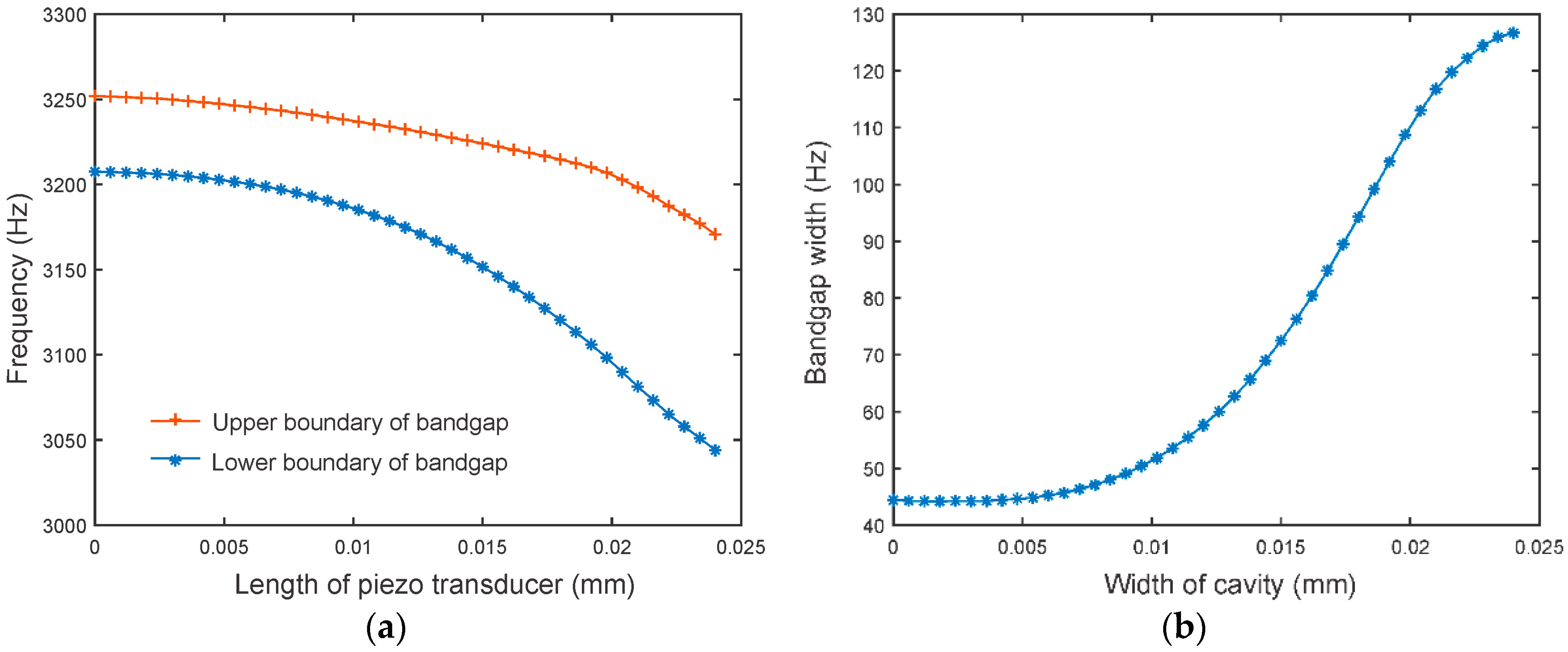
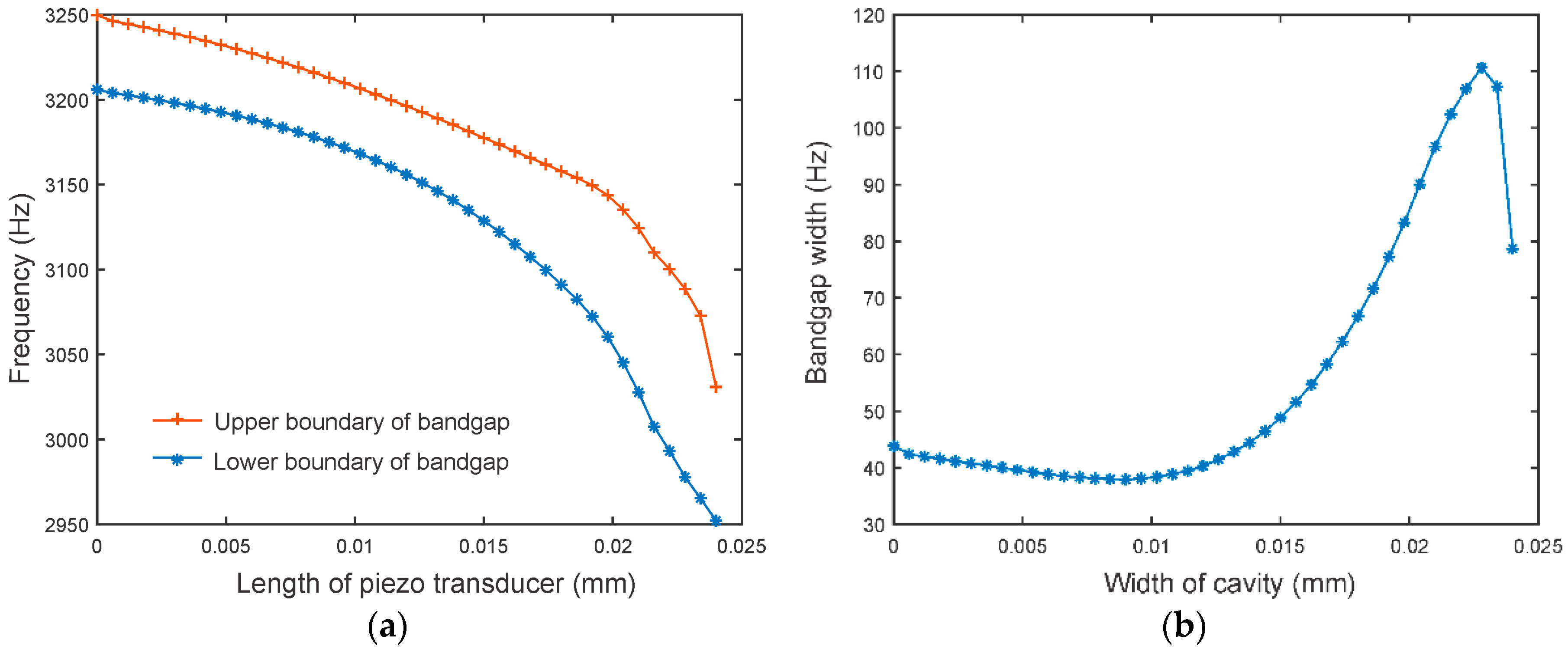
In this section, the parametric influence of the size of the cavity to bandgap width is investigated. Here cavities are incorporated with constant heights of 1 mm and 2 mm, respectively, and with constant length of 25.38 mm. The boundaries and the width of the bandgap under cavities with various widths, are then plotted in Figure 6 and Figure 7. These results are obtained through finite element analysis.
Figure 6 shows the frequency boundaries and the width of the bandgap. All the cavities have constant height of 1 mm and constant length of 25.38 mm. It can be observed that in these results all bandgaps are created in the vicinity of 3200 Hz, although the stiffness of the unit-cell has been significantly reduced. This is because the location of the bandgap is primarily determined by the frequency of the LC resonance. With the increase of the width of the cavity, the location of the bandgap shifts to a lower frequency range. This can be attributed to the fact that local stiffness of the unit-cell also affects the local resonant bandgap, as indicated in Equation (21). The relation between the bandgap width and the width of the cavity, is illustrated in Figure 6b. It can be observed that, by increasing the width of the cavity, the bandgap width of the piezoelectric metamaterial can be continuously increased. The reason is that, increasing the size of cavity increases the system-level electro-mechanical coupling coefficient. It is worth noting that the piezoelectric metamaterial with a cavity width of 24 mm, has bandgap expanded from 45 Hz to 126.7 Hz. Moreover, the proposed mechanism for broadening bandgap width of piezoelectric metamaterial does not preclude the utilization of piezoelectric transducers with larger coupling constant or negative capacitance circuitry integration. The bandgap width of the piezoelectric metamaterial can be further expanded by methods proposed previously.
Similarly, Figure 7 illustrates the frequency boundaries and the bandgap width of the unit-cell, where the cavity introduced has height of 2 mm. The results generally resemble those shown in Figure 6, i.e., the introduction of cavity underneath the substrate, can effectively increase the bandgap width. However, it is worth mentioning that in this case, the bandgap width decreases dramatically when the width of the cavity is increased to 22.8 mm. The shrinking of bandgap width is attributed to the fact that the mode of the unit-cell becomes uneven, i.e., the assumptions of displacements in Equation (10a,b) no longer hold. The non-sinusoidal mode of the unit-cell reduces the system level electro-mechanical coupling coefficient, and therefore reduces bandgap width.
3.3. Transmission Analysis
In this section, transmissions of the piezoelectric metamaterial beam through finite element analysis are presented. Here a piezoelectric metamaterial beam consisting of 12 unit-cells arranged in series is considered (Figure 3b). For simplicity and without loss of generality, the excitation is applied at the left end of the metamaterial beam. The displacement distributions and the forced responses at the right free-end are computed. The dispersion relations are obtained through the displacement distributions of the metamaterial beam by using Fournier transform [25,39],
where is the wavenumber and is the distribution of displacement in the longitude direction of the beam.
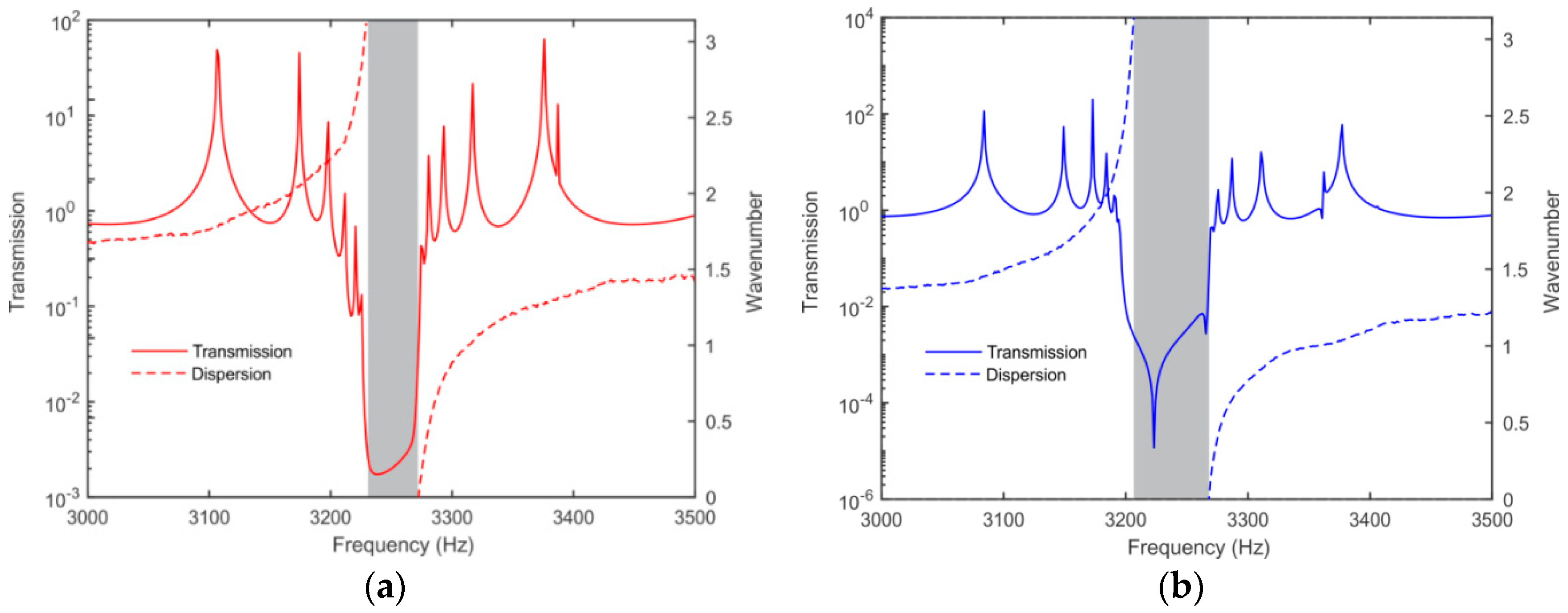
Plotted in Figure 8, are the transmission diagrams and the dispersion curves of the conventional metamaterial beam and the one with mm3 cavity incorporated. It can be observed that the bandgaps yielded strong wave attenuation effects in both cases. The piezoelectric metamaterial beam with cavity showed a broader frequency range of wave attenuation. Moreover, the relationship of the bandgap range and the wave attenuation range can be readily observed. Different from that shown by [33], where the frequency range of wave attenuation fully overlapped with the frequency range of bandgap, in this research, significant wave attenuation could be observed outside the bandgap range. For example, wave attenuation occurred between 3195 Hz and 3202 Hz, for the metamaterial beam with cavity. This phenomenon is attributed to the strong resonating (i.e., multiple peaks) near the bandgap, and the corresponding damping from the resonance motion of local resonator.
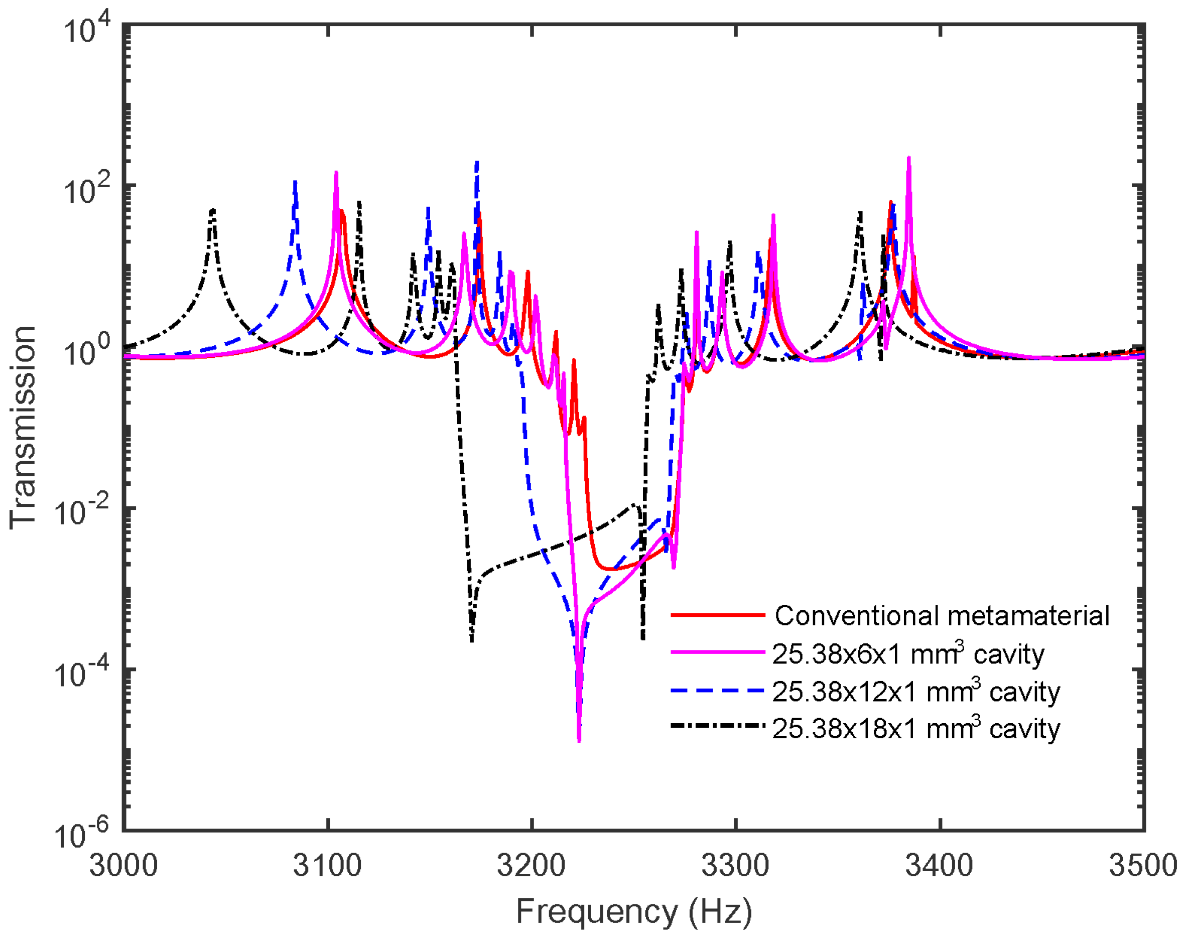
Further case studies are carried out to illustrate the influence of the dimension of the cavity to transmissions. Three cavities with the same length (25.38 mm) and height (1 mm), but different widths, 6 mm, 12 mm, and 18 mm, were analyzed. Figure 9 plots correspondingly, three transmission diagrams. It can be readily observed that increasing the width of the cavity can effectively increase the bandgap width. With the cavities, the bandgap widths were 51 Hz, 67 Hz, and 89 Hz, respectively. The transmission diagrams shown in Figure 9, further confirm that incorporating cavity can improve the bandgap behavior.
Finally, it is worth noticing that the introduction of cavity does not preclude the optimal arrangement of circuitry elements. For example, tunable negative capacitance elements have been employed in piezoelectric metamaterial synthesis, where the negative capacitance is realized through a negative impedance converter (NIC) [38]. A negative capacitance element can cancel out the inherence impedance of the piezoelectric transducer. Equivalently speaking, a negative capacitance element can reduce the system-level stiffness of the unit-cell. This integration can certainly be implanted in combination with the mechanical cavity concept studied in this research. In the past, tunable inductances based on op-amp circuit design have also been employed in vibration control and sensor development [28], as well as in metamaterial synthesis [23]. Integrating tunable inductance with the piezoelectric metamaterial studied in this research, will result in adaptiveness.
4. Conclusions
In this research, acoustic metamaterial consisting of piezoelectric transducers integrated to host substrate with inductive circuits was studied. A lumped-parameter, semi-analytical model of piezoelectric metamaterial was formulated based on continuum mechanics characterization. The equivalent unit-cell mass, stiffness, and electro-mechanical coupling parameter were derived, which were wavenumber-dependent. The role of the system-level electro-mechanical coupling was identified and analyzed in detail. While the frequency range of the bandgap is determined by the LC circuit resonant frequency, the bandwidth of the bandgap is primarily determined by the electro-mechanical coupling. Then, a method for bandwidth broadening through incorporating cavity in the substrate of the unit-cell was presented. Fundamentally, the cavity introduced could increase the system-level electro-mechanical coupling, thereby benefiting the bandgap behavior. It was demonstrated that the bandgap width of the piezoelectric metamaterial could be expanded from 45 Hz to 126.7 Hz. The analytical formulation and cavity synthesis can be used to guide the design optimization of the piezoelectric metamaterial.
Author Contributions
J.X. and J.T. conceived the idea and carried out the theoretical analysis. J.X. performed the FEM simulations. All authors discussed the results and contributed to the writing and editing of the manuscript.
Acknowledgments
This research was founded by NSF under grant CPS—1544707 and start-up funding of Southeast University, China, under grant 1122007115.
Conflicts of Interest
The authors declare no conflicts of interest.
Appendix A. Derivations of Lumped Parameters in Unit-Cell Equations of Motion
Equation (10a,b) can be re-written as
The lumped mechanical and electrical displacements of the unit-cell are denoted as, respectively
Recall Equation (9a,b). Correspondingly, the partial differential equations that govern the unit-cell dynamics can now be written as
The above two equations can be written in the forms of Equation (11a–c). Here we have two piezoelectric transducers in one unit-cell, and therefore we have two transducer equations. The coefficients in the lumped-parameter dynamic model are given as
After integrations, the coefficients shown in Equations are obtained Equation (12a–d).
References
- Liu, Z.; Zhang, X.; Mao, Y.; Zhu, Y.Y.; Yang, Z.; Chan, C.T.; Sheng, P. Locally resonant sonic materials. Science 2000, 289, 1734–1736. [Google Scholar] [CrossRef] [PubMed]
- Landy, N.I.; Sajuyigbe, S.; Mock, J.J.; Smith, D.R.; Padilla, W.J. Perfect metamaterial absorber. Phys. Rev. Lett. 2008, 100, 207402. [Google Scholar] [CrossRef] [PubMed]
- Pendry, J.B.; Li, J. An acoustic metafluid: Realizing a broadband acoustic cloak. New J. Phys. 2008, 10, 115032. [Google Scholar] [CrossRef]
- Yang, J.; Huang, M.; Yang, C.; Peng, J.; Chang, J. An external acoustic cloak with N-sided regular polygonal cross section based on complementary medium. Comput. Mater. Sci. 2010, 49, 9–14. [Google Scholar] [CrossRef]
- Bigoni, D.; Guenneau, S.; Movchan, A.B.; Brun, M. Elastic metamaterials with inertial locally resonant structures: Application to lensing and localization. Phys. Rev. B 2013, 87, 174303. [Google Scholar] [CrossRef]
- Baravelli, E.; Ruzzene, M. Internally resonating lattices for bandgap generation and low-frequency vibration control. J. Sound Vib. 2013, 332, 6562–6579. [Google Scholar] [CrossRef]
- Yoo, Y.J.; Zheng, H.Y.; Kim, Y.J.; Rhee, J.Y.; Kang, J.H.; Kim, K.W.; Cheong, H.; Kim, Y.H.; Lee, Y.P. Flexible and elastic metamaterial absorber for low frequency, based on small-size unit cell. Appl. Phys. Lett. 2014, 105, 041902. [Google Scholar] [CrossRef]
- Zhu, R.; Chen, Y.; Barnhart, M.; Hu, G.; Sun, C.T.; Huang, G. Experimental study of an adaptive elastic metamaterial controlled by electric circuits. Appl. Phys. Lett. 2016, 108, 011905. [Google Scholar] [CrossRef]
- Li, J.; Chan, C.T. Double-negative acoustic metamaterial. Phys. Rev. E 2004, 70, 055602. [Google Scholar] [CrossRef] [PubMed]
- Fang, N.; Lee, H.; Sun, C.; Zhang, X. Sub-diffraction-limited optical imaging with a silver superlens. Science 2005, 308, 534–537. [Google Scholar] [CrossRef] [PubMed]
- Yang, Z.; Mei, J.; Yang, M.; Chan, N.H.; Sheng, P. Membrane-type acoustic metamaterial with negative dynamic mass. Appl. Phys. Lett. 2008, 101, 204301. [Google Scholar] [CrossRef] [PubMed]
- Mei, J.; Ma, G.C.; Yang, M.; Yang, Z.; Wen, W.J.; Sheng, P. Dark acoustic metamaterials as super absorbers for low-frequency sound. Nat. Commun. 2012, 3, 756. [Google Scholar] [CrossRef] [PubMed] [Green Version]
- Zhao, L.; Conlon, S.C.; Semperlotti, F. Broadband energy harvesting using acoustic black hole structural tailoring. Smart Mater. Struct. 2014, 23, 065021. [Google Scholar] [CrossRef]
- Che, K.; Yuan, C.; Wu, J.; Qi, H.; Meaud, J. Three-dimensional-printed multistable mechanical metamaterials with a deterministic deformation sequence. ASME J. Appl. Mech. 2017, 84, 011004. [Google Scholar] [CrossRef]
- Liu, L.; Hussein, M.I. Wave motion in periodic flexural beams and characterization of the transition between Bragg scattering and local resonance. ASME J. Appl. Mech. 2012, 79, 011003. [Google Scholar] [CrossRef]
- Monsoriu, J.A.; Depine, R.A.; MartÝnez-Ricci, M.L.; Silvestre, E. Interaction between non-Bragg band gaps in 1D metamaterial photonic crystals. Opt. Express 2006, 14, 12958–12967. [Google Scholar] [CrossRef] [PubMed]
- Achaoui, Y.; Khelif, A.; Benchabane, S.; Robert, L.; Laude, V. Experimental observation of locally-resonant and Bragg band gaps for surface guided waves in a phononic crystal of pillars. Phys. Rev. B 2011, 83, 104201. [Google Scholar] [CrossRef]
- Huang, H.H.; Lin, C.K.; Tan, K.T. Attenuation of transverse waves by using a metamaterial beam with lateral local resonators. Smart Mater. Struct. 2016, 25, 085027. [Google Scholar] [CrossRef]
- Tan, K.T.; Huang, H.H.; Sun, C.T. Blast-wave impact mitigation using negative effective mass density concept of elastic metamaterials. Int. J. Impact Eng. 2014, 64, 20–29. [Google Scholar] [CrossRef]
- Thorp, O.; Ruzzene, M.; Baz, A. Attenuation of wave propagation in fluid-loaded shells with periodic shunted piezoelectric rings. Smart Mater. Struct. 2005, 14, 594–604. [Google Scholar] [CrossRef]
- Airoldi, L.; Ruzzene, M. Wave propagation control in beams through periodic multi-branch shunts. J. Intell. Mater. Syst. Struct. 2011, 22, 1567–1579. [Google Scholar] [CrossRef]
- Wang, G.; Chen, S. Large low-frequency vibration attenuation induced by arrays of piezoelectric patches shunted with amplifier-resonator feedback circuit. Smart Mater. Struct. 2016, 25, 015004. [Google Scholar] [CrossRef]
- Wang, G.; Chen, S.; Wen, J. Low-frequency locally resonant band gaps induced by arrays of resonant shunts with Antoniou’s circuit: Experimental investigation on beams. Smart Mater. Struct. 2010, 20, 015026. [Google Scholar] [CrossRef]
- Xu, J.; Tang, J. Tunable Prism Based on Piezoelectric Metamaterial for Acoustic Beam Steering. Appl. Phys. Lett. 2017, 110, 181902. [Google Scholar] [CrossRef]
- Xu, J.; Li, S.; Tang, J. Customized Shaping of Vibration Modes by Acoustic Metamaterial Synthesis. Smart Mater. Struct. 2018, 27, 045001. [Google Scholar] [CrossRef]
- Casadei, F.; Ruzzene, M.; Dozio, L.; Gunefare, K.A. Broadband vibration control through periodic arrays of resonant shunts: Experimental investigation on plates. Smart Mater. Struct. 2010, 19, 015002. [Google Scholar] [CrossRef]
- Tang, J.; Wang, K.W. Vibration delocalization of nearly periodic structures using coupled piezoelectric networks. ASME J. Vib. Acoust. 2003, 125, 95–108. [Google Scholar] [CrossRef]
- Wang, K.W.; Tang, J. Adaptive Structural Systems with Piezoelectric Transducer Circuitry; Springer: New York, NY, USA, 2008. [Google Scholar]
- Zhao, J.; Wang, X.; Tang, J. Damping reduction in structures using piezoelectric circuitry with negative resistance. ASME J. Vib. Acoust. 2011, 133, 041009. [Google Scholar] [CrossRef]
- Narisetti, R.K.; Leamy, M.J.; Ruzzene, M. A perturbation approach for predicting wave propagation in one-dimensional nonlinear periodic structures. ASME J. Vib. Acoust. 2010, 132, 031001. [Google Scholar] [CrossRef]
- Hu, G.; Tang, L.; Banerjee, A.; Das, R. Meta-structure with piezoelectric element for simultaneous vibration suppression and energy harvesting. ASME J. Vib. Acoust. 2016, 139, 011012. [Google Scholar] [CrossRef]
- Parra, E.A.F.; Bergamini, A.; Kamm, L.; Zbinden, P.; Ermanni, P. Implementation of integrated 1d hybrid phononic crystal through miniaturized programmable virtual inductances. Smart Mater. Struct. 2017, 26, 067001. [Google Scholar] [CrossRef]
- Zhu, R.; Liu, X.N.; Huang, G.L.; Huang, H.H.; Sun, C.T. Microstructural design and experimental validation of elastic metamaterial plates with anisotropic mass density. Phys. Rev. B 2012, 25, 144307. [Google Scholar] [CrossRef]
- ANSI/IEEE Std. 176-1987 IEEE Standard on Piezoelectricity; IEEE Standards Association: Piscataway, NJ, USA, 1988.
- Huang, G.; Sun, C.T. Band gaps in a multiresonator acoustic metamaterial. ASME J. Vib. Acoust. 2010, 132, 031003. [Google Scholar] [CrossRef]
- Collet, M.; Ouisse, M.; Ichchou, M.N. Structural energy flow optimization through adaptive shunted piezoelectric metacomposite. J. Intell. Mater. Syst. Struct. 2012, 23, 1661–1677. [Google Scholar] [CrossRef]
- Pai, P.F.; Peng, H.; Jiang, S. Acoustic metamaterial beams based on multi-frequency vibration absorbers. Int. J. Mech. Sci. 2014, 79, 195–205. [Google Scholar] [CrossRef]
- Tang, J.; Wang, K.W. Active-passive hybrid piezoelectric networks for vibration control: Comparisons and improvement. Smart Mater. Struct. 2001, 10, 794–806. [Google Scholar] [CrossRef]
- Massimo, R. Frequency–wavenumber domain filtering for improved damage visualization. Smart Mater. Struct. 2007, 16, 2166. [Google Scholar]
Figure 1.
Unit-cell of piezoelectric metamaterial.

Figure 2.
Equivalent circuit model of a unit-cell.

Figure 3.
(a) Unit-cell with cavity; (b) Configuration of the piezoelectric metamaterial and the coordinate system.
Figure 3.
(a) Unit-cell with cavity; (b) Configuration of the piezoelectric metamaterial and the coordinate system.

Figure 4.
Stiffness ratio and electro-mechanical coupling ratio vs the width of the cavity.

Figure 5.
Dispersion curves. (a) Unit-cell without cavity; (b) Unit-cell with cavity of 25.38 × 12 × 1 mm3; (c) Zoom in curves for unit-cell without cavity; (d) Zoom in curves for unit-cell with cavity.
Figure 5.
Dispersion curves. (a) Unit-cell without cavity; (b) Unit-cell with cavity of 25.38 × 12 × 1 mm3; (c) Zoom in curves for unit-cell without cavity; (d) Zoom in curves for unit-cell with cavity.

Figure 6.
Unit-cell with cavity with height of 1 mm. (a) Boundaries of the bandgap; (b) Bandgap width.
Figure 6.
Unit-cell with cavity with height of 1 mm. (a) Boundaries of the bandgap; (b) Bandgap width.

Figure 7.
Unit-cell with cavity with height of 2 mm. (a) Boundaries of the bandgap; (b) Bandgap width.
Figure 7.
Unit-cell with cavity with height of 2 mm. (a) Boundaries of the bandgap; (b) Bandgap width.

Figure 8.
Frequency response and dispersion relation. (a) Conventional metamaterial beam; (b) Metamaterial beam with cavity.
Figure 8.
Frequency response and dispersion relation. (a) Conventional metamaterial beam; (b) Metamaterial beam with cavity.

Figure 9.
Transmission diagrams for piezoelectric metamaterial beam.

© 2018 by the authors. Licensee MDPI, Basel, Switzerland. This article is an open access article distributed under the terms and conditions of the Creative Commons Attribution (CC BY) license (http://creativecommons.org/licenses/by/4.0/).
Share and Cite
MDPI and ACS Style
Xu, J.; Yan, R.; Tang, J. Broadening Bandgap Width of Piezoelectric Metamaterial by Introducing Cavity. Appl. Sci. 2018, 8, 1606. https://doi.org/10.3390/app8091606
AMA Style
Xu J, Yan R, Tang J. Broadening Bandgap Width of Piezoelectric Metamaterial by Introducing Cavity. Applied Sciences. 2018; 8(9):1606. https://doi.org/10.3390/app8091606
Chicago/Turabian StyleXu, Jiawen, Ruqiang Yan, and J. Tang. 2018. "Broadening Bandgap Width of Piezoelectric Metamaterial by Introducing Cavity" Applied Sciences 8, no. 9: 1606. https://doi.org/10.3390/app8091606
Note that from the first issue of 2016, this journal uses article numbers instead of page numbers. See further details here.