Article

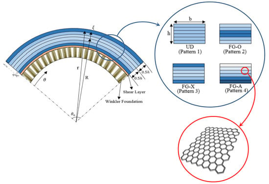
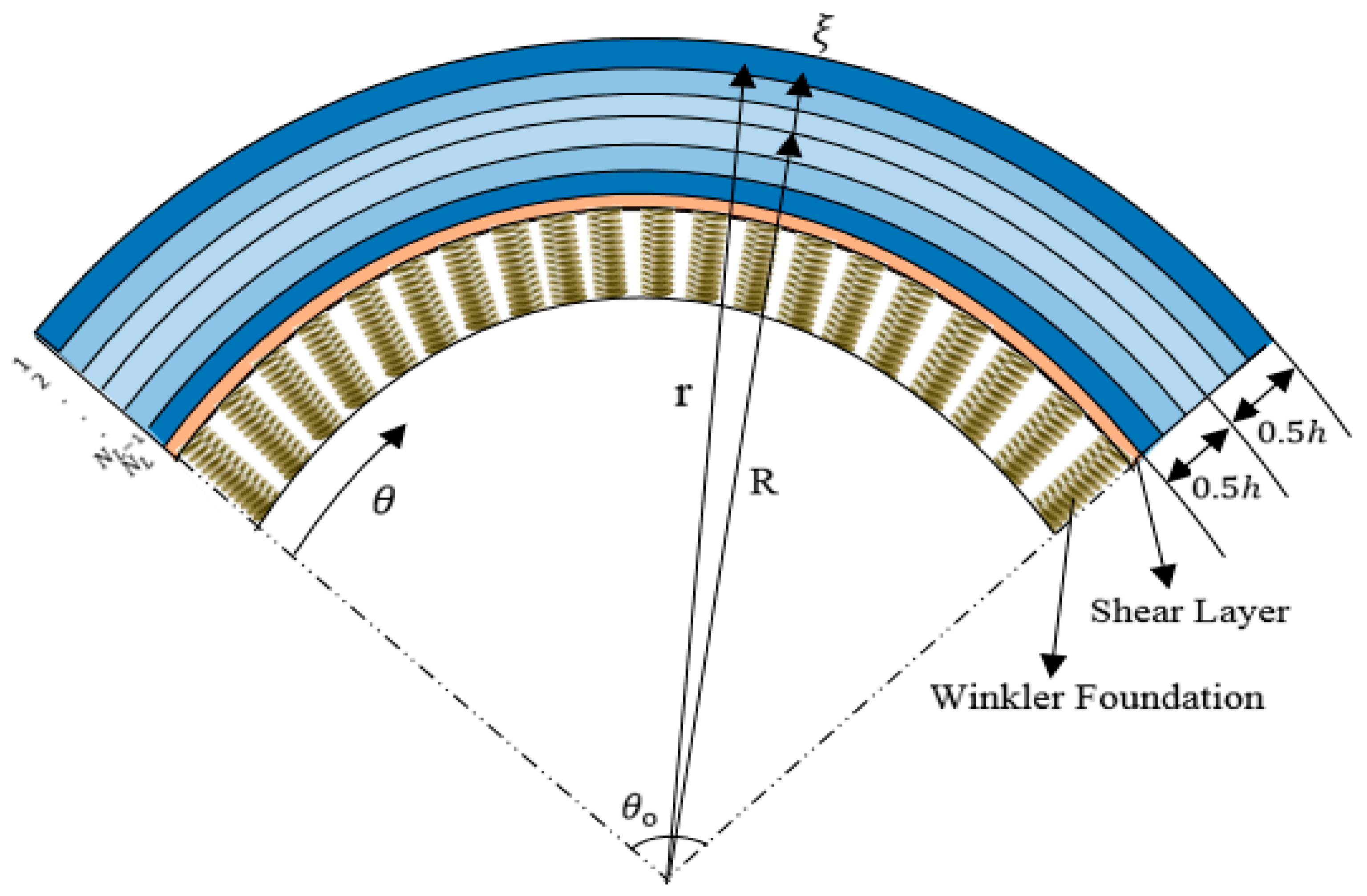
Size-Dependent Free Vibrations of FG Polymer Composite Curved Nanobeams Reinforced with Graphene Nanoplatelets Resting on Pasternak Foundations

by
Mohammad Arefi
1,
Elyas Mohammad-Rezaei Bidgoli
1,
Rossana Dimitri
2,
Francesco Tornabene
2,* and
J. N. Reddy
3
1
Department of Solid Mechanics, Faculty of Mechanical Engineering, University of Kashan, Kashan 87317-51167, Iran
2
Department of Innovation Engineering, University of Salento, 73100 Lecce, Italy
3
Advanced Computational Mechanics Laboratory, Department of Mechanical Engineering, Texas A&M University, College Station, TX 77843, USA
*
Author to whom correspondence should be addressed.
Appl. Sci. 2019, 9(8), 1580; https://doi.org/10.3390/app9081580
Submission received: 9 March 2019 / Revised: 10 April 2019 / Accepted: 11 April 2019 / Published: 16 April 2019
(This article belongs to the Special Issue Recent Advances in Non-Local Modelling of Nano-Structures)

Abstract

:
This paper presents a free vibration analysis of functionally graded (FG) polymer composite curved nanobeams reinforced with graphene nanoplatelets resting on a Pasternak foundation. The size-dependent governing equations of motion are derived by applying the Hamilton’s principle and the differential law consequent (but not equivalent) to Eringen’s strain-driven nonlocal integral elasticity model equipped with the special bi-exponential averaging kernel. The displacement field of the problem is here described in polar coordinates, according to the first order shear deformation theory. A large parametric investigation is performed, which includes different FG patterns, different boundary conditions, but also different geometrical parameters, number of layers, weight fractions, and Pasternak parameters.

Graphical Abstract

1. Introduction

The continuous development of novel materials with increased mechanical performances and low density has encouraged the adoption of novel reinforcements, such as carbon nanotubes and graphene platelets. It is well known from the literature that the addition of carbon nanotubes and graphene platelets within a matrix leads to a general increase of the structural stiffness and a decrease of the density. In the experimental results by Rafiee et al. [1], for example, the Young’s modulus of the epoxy matrix was increased by 31%, with the addition of 0.1% of graphene platelet reinforcement. Based on another experimental investigation performed by Liang et al. [2], the introduction of 0.7% of weight fraction of graphene platelet reinforcement in the matrix was demonstrated to increase the tensile strength by 76%, and the Young’s modulus by 62%. Despite a large amount of experimental and theoretical studies, the literature has focused on the mechanical response of structures reinforced with carbon nanotubes, with an increased attention has been paid to composite structures reinforced with graphene nanoplatelets (GPLs), as in the following review.
Shen et al. [3] analytically studied the vibration behavior of functionally graded (FG) graphene-reinforced composite laminated plates, accounting for the nonlinear strain field and the presence of an elastic foundation. A perturbation method was adopted by the authors to derive the nonlinear natural frequencies of FG graphene-reinforced composites, and to evaluate the sensitivity of the mechanical response to different boundary conditions, reinforcement patterns, and foundation parameters. A buckling analysis of cylindrical shells reinforced with graphene platelet was also performed by Wang et al. [4], where the effective mechanical properties of the material were evaluated based on the Halpin-Tsai micromechanical model and the rule of mixtures.
The free and forced vibration response of FG multilayer GPL/polymer composite plates was also studied by Song et al. [5], according to the first-order shear deformation plate theory. Navier’s solution was proposed to derive the explicit expressions for natural frequencies and amplitudes of free and forced vibrations. Based on a parametric investigation, the authors verified the high sensitivity of the mechanical response on the GPL weight fraction, as well as on the number of layers and dimensionless geometrical parameters. In addition, Feng et al. [6] presented the main results of a nonlinear free vibration analysis of beams reinforced by graphene platelets. The problem was formulated according to the Timoshenko’s beam theory and solved numerically by applying the Ritz method. The authors, in their work, verified the high sensitivity of the nonlinear vibration response to different reinforcement distributions, weight fractions, geometry, dimensions, and total number of layers.
A different approach based on the third-order shear deformation theory and nonlocal strain gradient beam model was used by Sahmani and Aghdam [7] for the nonlinear vibration analysis of FG graphene platelet-reinforced composite nanobeams. Hamilton’s principle was used to derive the nonlinear governing equations of motion, whereas an analytical expression for the nonlinear size-dependent natural frequencies was determined by means of the perturbation technique and Galerkin method.
Zhao et al. [8] investigated the bending and vibration response of FG trapezoidal plates reinforced with GPLs based on the finite element method. In detail, the effective modulus of elasticity, together with the Poisson’s ratio and density, were computed according to the Halpin-Tsai micro-mechanical model and the rule of mixtures. The static and dynamic behavior of the reinforced plate was evaluated for varying patterns and weight fractions of GPL. A further work based on Timoshenko’s beam theory and von Kármán nonlinear relations was proposed by Chen et al. [9] to study the free vibration and post buckling behavior of multilayer FG porous nanocomposite beams reinforced by GPLs. The authors applied a direct iterative algorithm and Ritz method to investigate the influence of the weight fraction and dispersion pattern within the material, as well as the geometry and dimension of the structure. Furthermore, Wang et al. [10] applied the finite element approach to evaluate the stability of FG graphene platelet-reinforced cylindrical shells, including a cutout. A large parametric investigation was performed numerically to investigate the influence of the weight fraction, geometry and distribution of GPLs, total number of layers, shell dimensions, and location of the cutout on the buckling response.
In addition, Yang et al. [11] presented a three dimensional thermo-elastic analysis of axially symmetric FG polymer nanocomposite circular and annular plates reinforced with GPLs subjected to coupled thermal-mechanical loading. The problem was solved based on the generalized method proposed by Mian and Spencer, according to which a low content of GPLs was required to significantly improve the global stiffness of the plate. Kitipornchai et al. [12] applied Timoshenko’s beam theory for the analysis of the free vibration and buckling behavior of FG porous nanocomposite beams, with various distributions of internal pores and graphene platelets. Based on a large numerical investigation, an effective increase of the stiffness was reached for a uniform distribution of the porosity and GPL within the matrix. A different approach based on the first order shear deformation theory and von-Karman nonlinear strain theory was applied by Song et al. [13] for the nonlinear analysis of the buckling and post buckling response of FG multilayer composite plates reinforced with GPLs. Thus, an eigenvalue problem was solved by the authors using a two-step perturbation technique. A further interesting work on the topic was proposed by Feng et al. [14], who studied the nonlinear bending behavior of multi-layer polymer nanocomposite beams reinforced with graphene platelets, based on the Timoshenko’s beam theory, as well as the von Kármán nonlinear relations and the Ritz method. Based on the numerical results, the nonlinear deformations of the nanostructure were unaffected by symmetrical distributions of graphene platelets. Similarly, Gholami and Ansari [15] applied the von Kármán nonlinear strain-displacement relations together with a sinusoidal shear deformation plate approach to investigate the nonlinear bending response of FG multilayer graphene platelet-reinforced polymer composite materials.
Many other works in the literature have focused on the static, dynamic, and buckling behavior of FG-reinforced nanobeams and nanostructures [16,17,18,19,20,21,22,23,24,25,26,27,28,29,30,31,32,33,34,35,36,37,38,39,40,41,42,43,44,45,46,47,48,49]. More specifically, Song et al. [16] employed the first-order shear deformation theory for the bending and compressive buckling analysis of FG multilayer GPLs. The effective Young’s modulus of the nanocomposites and Poisson’s ratio were determined using the Halpin-Tsai micromechanics model and the rule of mixtures, respectively. Hosseini and Rahmani [17] studied the free vibration problem of a FG curved nanobeam by applying Hamilton’s principle. The Navier method was proposed by the authors to solve the governing equations of motion for a simply-supported curved nanobeam, while evaluating the sensitivity of the response to the nonlocal parameter, opening angle, aspect ratio, mode number, and gradient index. A nonlocal strain gradient elasticity theory and higher order hyperbolic refined beam theory were suggested by Ebrahimi and Barati [18] as alternative tools to solve the buckling problems of FG curved nanobeams. The numerical results were evaluated comparatively with respect to the straight configuration, assumed as the reference geometry (i.e., for an infinite radius of curvature), and the main effect of the nonlocal parameter, length scale, power-law exponent, boundary condition, and slenderness ratio were evaluated on the buckling load of curved nanobeams. A free vibration study of curved sandwich nanobeams was also performed by Rahmani et al. [19], according to the Eringen’s nonlocal theory, whereby a meaningful decrease of the natural frequency was observed for increasing opening angles of the nanostructures.
A further study of the statics and dynamics of curved single-walled carbon nanotubes was approached by Hayati et al. [20], based on the nonlocal theory, whose problem was solved using Navier’s method. A different approach based on the sinusoidal shear deformation theory was applied by Arefi and Zenkour [21,22] for the analysis of a sandwich microbeam and nanoplate, respectively. Some additional static and dynamic analyses of curved beams at the nano- and macro-scales were presented by Aya and Tufekci [23], as well as by Hajianmaleki and Qatu [24], respectively. A nonlocal elasticity solution and wave propagation analysis of nanoplates and nanorods were proposed by Arefi and Zenkour [25,26], whereas the sinusoidal shear deformation theory was applied for the study of the transient response of curved beams [27]. A large variety of size-dependent theories of elasticity have been applied recently in literature to study the mechanics of nanostructures, including Eringen’s nonlocal models [28,29,30,31], modified couple stress theories [32,33,34,35,36], and nonlocal strain gradient laws [37,38]. Many further coupled nonlinear problems involving composite nanostructures can be found in previous studies [39,40,41,42,43,44,45,46,47,48,49].
Based on the available literature on the vibration and bending response of beams and plates reinforced with GPLs at the macroscale [3,4,5,6,7,8,9,10,11,12,13,14,15,16,17], as well as on the curved beams at the macro- and nano-scales [18,19,20,21,22,23,24,25,26,27], here we propose a combined study of curved nanobeams reinforced with nanoplatelets. In mechanical problems of technical interest, the elastic equilibrium is generally defined in bounded structural domains, so that suitable constitutive boundary conditions have to be prescribed to ensure the equivalence between integral and differential equations [33]. It has been recently proven that constitutive boundary conditions are in contrast with equilibrium requirements, so that Eringen’s strain-driven integral model leads to ill-posed structural problems, and therefore it is inapplicable to nanostructures. These difficulties have been overcome by adopting the innovative stress-driven nonlocal integral formulation of elasticity recently proposed in a previous study [33] and applied to static, thermal, vibration, and buckling problems in several papers.
Herein, we tackle the problem according to Eringen’s nonlocal differential model and the first order shear deformation theory, where the vibration response of FG polymer composite curved nanobeams reinforced with GPLs is analyzed in detail, as useful for practical engineering applications. The Halpin-Tsai model and the rule of mixtures are here applied to compute the effective Young’s modulus, density, and Poisson’s ratio of the FG curved nanobeam, respectively. The analytical solution of the problem is here analyzed parametrically for varying boundary conditions, reinforcement distributions, weight fractions, number of layers, and Pasternak foundation parameters, while evaluating the sensitivity of the vibration global response.
The paper is organized as follows: in Section 2 the effective material properties and constitutive relations are detailed; Section 3 is devoted to the numerical solution of the problem; a number of illustrative applications are discussed and compared to the available literature in Section 4, and, finally, in Section 5 the concluding remarks are reported.

2. Effective Material Properties and Constitutive Relations

Consider a curved nanobeam with length L, thickness h, and width b (Figure 1). The composite nanobeam is reinforced by GPLs, with N L layers of thickness Δ h = h / N L . The reinforcement features a uniform distribution within the polymer matrix at each layer. The GPL weight fraction changes linearly along the thickness direction to form a FG material structure. Four patterns are herein considered for functionalities, namely, a uniform distribution (UD) (labeled also as Pattern 1), two FG symmetric distributions (labeled as FG-O and FG-X Patterns, or equivalently Pattern 2 and 3), and an asymmetrical FG distribution (labeled as FG-A Pattern, or equivalently, Pattern 4), see Figure 2. The weight fraction of GPLs is, thus, varied along thickness direction, whereas the effective Young’s modulus of each nanocomposite layer is computed based on the Halpin-Tsai algebraic formula, as follows [50]
E C ( k ) = 3 8 ( 1 + ξ L η L V G P L ( k ) 1 η L V G P L ) × E M + 5 8 ( 1 + ξ w η w V G P L ( k ) 1 η w V G P L ) × E M
where
η L = ( E G P L / E M ) 1 ( E G P L / E M ) + ξ L
η w = ( E G P L / E M ) 1 ( E G P L / E M ) + ξ W
and E M , E G P L stand for the Young’s modulus of the polymer and GPLs, respectively.
In addition, in Equation (1), V G P L ( k ) is the volume fraction of GPLs for each layer, while ξ L , ξ w denote two dimensionless length and weight parameters, depending on the dimension of GPLs, as follows
ξ L = 2 ( l G P L h G P L )
ξ w = 2 ( w G P L h G P L )
With l G P L , w G P L , h G P L being the length, width, and thickness of GPL, respectively. In addition, V G P L ( k ) is defined as follows
V G P L ( k ) = g G P L ( k ) g G P L ( k ) + ( ρ G P L / ρ M ) ( 1 g G P L ( k ) )
in which g G P L ( k ) is the weight fraction of GPL at each layer, ρ M and ρ G P L denote the density of the polymer and GPL, respectively.
The effective density and Poisson’s ratio of the nanocomposite material are defined analytically, according to the rule of mixtures, as follows
ρ C ( k ) = ρ G P L V G P L ( k ) + ρ M V M ( k ) ν C ( k ) = ν G P L V G P L ( k ) + ν M V M ( k )
with ν M , ν G P L being the Poisson’s ratio of the polymer and GPL, respectively. Moreover, V M ( k ) is the volume fraction of the polymer at each layer. The weight fraction of the GPLs for each selected distribution reads as follows [16]
g G P L ( k ) = { g G P L U D ( P a t t e r n   1 ) 4 g G P L ( N L + 1 2 | k N L + 1 2 | ) / ( 2 + N L ) F G - O   ( P a t t e r n   2 ) 4 g G P L ( 1 2 + | k N L + 1 2 | ) / ( 2 + N L ) F G - X   ( P a t t e r n   3 ) 2 k g G P L / ( N L + 1 ) F G - A   ( P a t t e r n   4 )
where g G P L denote the weight fraction of GPL.
Now we introduce the constitutive relations of the nanocomposite curved nanobeam, based on the first order shear deformation theory. Thus, the displacement field is defined as [51,52]
u r ( r , θ , t ) = u r ( θ , t )
u θ ( r , θ , t ) = u θ ( θ , t ) + ζ χ ( θ , t )
where ζ = r R denotes the general distance from the reference surface. In addition, u r ( θ , t ) and u θ ( θ , t ) refer to the radial and circumferential displacement components at the middle surface and χ ( θ , t ) is the rotation function.
Based on the previous displacement relations, the strain components are determined as
ε r r = u r r = 0
ε θ θ = u r r + 1 r u θ θ = u r R + ζ + 1 R + ζ u θ θ + ζ R + ζ χ θ
ε r θ = 1 r u r θ + u θ r u θ r = 1 R + ζ u r θ + χ u θ R + ζ ζ R + ζ χ
The whole analysis is based on the differential constitutive formulation [53,54,55,56], which can be considered equivalent to the original Eringen integral convolution only for nonlocal problems defined in unbounded domains, involving screw dislocations and surface waves [53]
( 1 μ 2 2 ) σ θ θ ( k ) = E C ( k ) ε θ θ ( k )
( 1 μ 2 2 ) σ r θ ( k ) = G C ( k ) ε r θ ( k )
where μ is the nonlocal parameter and G C ( k ) is the shear modulus at each layer.
Thus, the size-dependent governing equations of the problem are derived by applying Hamilton’s principle, as follows
δ ( U T V ) d t = 0
whose variation of the strain energy is expressed as [50]
δ U = V ( σ θ θ δ ε θ θ + σ r θ δ ε r θ ) d V
By definition of the volume element as d V = b r d r d θ = b ( R + ζ ) d ζ d θ , we can redefine the variation of the strain energy as
δ U = V { σ θ θ [ δ u r R + ζ + 1 R + ζ δ u θ θ + ζ R + ζ δ χ θ ] + k s σ r θ [ 1 R + ζ δ u r θ + R R + ζ δ χ δ u θ R + ζ ] } b ( R + ζ ) d ζ d θ
where we set the shear stress correction factor to k s = 5 / 6 . By definition of resultant components, the variation of strain energy is expressed as follows
δ U = A [ N θ θ δ u r N θ θ θ δ u θ M θ θ θ δ χ N r θ θ δ u r + R N r θ δ χ N r θ δ u θ ] b d θ
where the resultant components are expressed as in the following
N θ θ = h 2 h 2 σ θ θ d ζ ,   N r θ = h 2 h 2 k s σ r θ d ζ ,   M θ θ = h 2 h 2 ζ σ θ θ d ζ
By combination of Equations (12)–(16),(19),(20), we get the following relations between the resultant components and the displacement field components, namely
( 1 μ 2 2 ) N θ θ = A 4 u r + A 4 u θ θ + A 5 χ θ ( 1 μ 2 2 ) N r θ = A 6 u θ + A 6 u r θ + A 7 χ ( 1 μ 2 2 ) M θ θ = A 5 u r + A 5 u θ θ + A 8 χ θ
More details about the analytical expressions for the integration constants of Equation (21) A j can be found in Appendix A.
The external work related to the Pasternak foundation is defined as
δ V = A ( R f ) δ u r d A
R f = k 1 u r k 2 2 u r
where R f is the reaction force of the Pasternak foundation, k 1 and k 2 are the associated elastic parameters, and 2 is the Laplacian operator in polar coordinate, namely, 2 = 1 r 2 2 θ 2 . Thus, the reaction force of the Pasternak foundation is expressed as
R f = k 1 u r k 2 1 ( R h 2 ) 2 2 u r θ 2
whereas the variation of the external work reads
δ V = [ R f ( R h 2 ) ] b δ u r d θ
The variation of kinetic energy is defined as
δ T = V ρ V . δ V d V
By substitution of the velocity components in terms of fundamental unknowns, Equation (27) becomes
δ T = A ( A 1 2 u r t 2 δ u r + A 1 2 u θ t 2 δ u θ + A 2 2 χ t 2 δ u θ + A 2 2 u θ t 2 δ χ + A 3 2 χ t 2 δ χ ) b d θ
whose integration constants A j are expressed in Appendix A.
By substituting the variations of the strain energy, the kinetic energy, and the external work into the Hamilton’s principle, we get the following governing equations of the problem
δ u r : N θ θ N r θ θ [ ( R h 2 ) R f ] = A 1 2 u r t 2
δ u θ : N θ θ θ N r θ = ( A 1 2 u θ t 2 + A 2 2 χ t 2 )
δ χ : M θ θ θ + R N r θ = ( A 2 2 u θ t 2 + A 3 2 χ t 2 )
After a further substitution of the resultant components with the displacement variables, the governing equations of the problem become
δ u r : A 4 u r + A 4 u θ θ + A 5 χ θ + A 6 u θ θ A 6 2 u r θ 2 A 7 χ θ ( R h 2 ) [ ( k 1 u r k 2 1 ( R h 2 ) 2 2 u r θ 2 ) μ 2 1 ( R h 2 ) 2 ( k 1 2 u r θ 2 k 2 1 ( R h 2 ) 2 4 u r θ 4 ) ] = A 1 2 u r t 2 A 9 μ 2 4 u r θ 2 t 2
δ u θ : A 4 u r θ A 4 2 u θ θ 2 A 5 2 χ θ 2 + A 6 u θ A 6 u r θ A 7 χ = A 1 2 u θ t 2 + A 9 μ 2 4 u θ θ 2 t 2 A 2 2 χ t 2 + A 10 μ 2 4 χ θ 2 t 2
δ χ : A 5 u r θ A 5 2 u θ θ 2 A 8 2 χ θ 2 + R ( A 6 u θ + A 6 u r θ + A 7 χ ) = A 2 2 u θ t 2 + A 10 μ 2 4 u θ θ 2 t 2 A 3 2 χ t 2 + A 11 μ 2 4 χ θ 2 t 2

3. Solution Procedure

This section is devoted to the analytical procedure here adopted to solve the problem for FG curved nanobeams with different boundary conditions. More specifically, clamped-clamped (C-C), clamped-simply supported (C-S), and simply supported-simply supported (S-S) boundary conditions are here assumed for comparative purposes. The natural frequencies of the system are here evaluated as follows [55]
u r ( θ , t ) = m = 1 U r X m ( θ ) e i ω t
u θ ( θ , t ) = m = 1 U θ X m ( θ ) θ e i ω t
χ ( θ , t ) = m = 1 X X m ( θ ) θ e i ω t
With { X } = { U r , U θ , X } T being the displacement vector. The admissible functions for X m ( θ ) are assumed, as detailed in Table 1, where β m = m π R / L and R = L θ 0 .
For example, for a S-S boundary condition, the substitution of the time-dependent displacement field into the governing equations of motion leads to the following characteristics equation
( [ K ] ω 2 [ M ] ) { X } = { 0 }
in which [ K ] and [ M ] stand for the stiffness and mass matrices, whose components are detailed in what follows
K 11 = A 4 + A 6 β m 2 ( R h 2 ) [ ( k 1 + k 2 β m 2 ( R h 2 ) 2 ) μ 2 1 ( R h 2 ) 2 ( k 1 β m 2 k 2 β m 4 ( R h 2 ) 2 ) ] K 12 = ( A 4 + A 6 ) β m K 13 = ( A 5 + A 7 ) β m K 22 = A 4 β m 2 + A 6 K 23 = A 5 β m 2 A 7 K 33 = A 8 β m 2 + R A 7 M 11 = A 1 + A 9 μ 2 β m 2 M 12 = 0 M 13 = 0 M 22 = A 1 + A 9 μ 2 β m 2 M 23 = A 2 + A 10 μ 2 β m 2 M 33 = A 3 + A 11 μ 2 β m 2

4. Numerical Results and Discussion

The accuracy of the proposed method is first assessed by means of a comparative evaluation of our numerical results with predictions available in the literature. It follows a large parametric investigation to check for the sensitivity of the response to different input mechanical and geometrical features of the material and nanostructure.

Comparison and Validation

As first example, we assume a S-S FG curved nanobeam of width B=1 nm, length L = 10 nm, made of Al and SiC material with elastic moduli EAl = 70 GPa, ESiC = 427 GPa, Poisson’s ratios νAl = 0.3, νSiC = 0.17, densities ρ = 2702 k g m 3 , ρ = 3100 k g m 3 , respectively. The material and geometry of the nanostructure are here selected according to the reference work by Hosseini and Rahmani [17] for comparative purposes. Table 2 summarizes the main results of the first three natural frequencies for a varying dimensionless length-to-thickness ratio L h between 10 and 50, as well as for different values of the nonlocal parameter μ 2 , while keeping constant n = 1 and α = π / 2 . Based on Table 2, it is worth noticing a gradual decrease of each natural frequency for an increasing value of the nonlocal parameter, together with a gradual increase for an increased length-to-thickness ratio L h , in line with predictions by Hosseini and Rahmani [17]. The very good agreement between our results and predictions from the literature clearly confirms the reliability and accuracy of the proposed method to capture the vibration response of the problem.
A further study compares the first natural frequency of the curved nanobeam for two different boundary conditions, namely S-S, and C-C, as well as for two different length-to-thickness ratios L h (i.e., L h = 10 ,   20 ), two different opening angles (i.e., θ 0 = π / 3 ,   π / 6 ), and different nonlocalities. The outcomes in Table 3 clearly show that the natural frequency increases for an increased length-to-thickness ratio, L h , and an increased opening angle, θ , whereas it decreases for an increased nonlocal parameter μ . As also expected, a C-C boundary condition enables higher values of the natural frequency, compared to a S-S boundary condition, under the same geometrical and non-local assumptions, L h , θ , and μ . The satisfactory agreement between our results and predictions in a previous study [57] confirms, once again, the capability of the proposed method for correctly reproducing the vibration response of composite nanobeams.
Furthermore, we continue the investigation by analyzing the possible effect of some geometrical and mechanical parameters of the nanobeam on its global response, namely, the opening angle θ 0 , the weight fraction g G P L , the total number of layers N L , the nonlocal parameter μ , the dimensionless length-to-thickness ratio of the GPL, l G P L h G P L , and the foundation parameters, k 1 ,   k 2 .
All the computations are performed for a polymer matrix with elastic properties E m a t r i x = 1.01   T P a ,   ν m a t r i x = 0.186 , and density ρ m a t r i x = 1062.5   k g / m 3 , and a dispersed GPL reinforcement with the following properties E G P L = 3   G P a ,   ν G P L = 0.34 ,   ρ G P L = 1200   k g / m 3 . In what follows, we consider a nanobeam of thickness h = 5   n m and length L = 20 h , whereas the GPL reinforcement has length l G P L = 2.5   n m , thickness h G P L = 0.15   n m , and weight w G P L = 1.5   n m .
Table 4 collects the results in terms of the first natural frequency for increasing values of the nonlocal parameter μ , and weight fraction g G P L , as well as for different boundary conditions (C-C, C-S, and S-S, respectively), while keeping constant the total number of layers N L = 12 , the opening angle θ 0 = π 6 Rad, and the foundation parameters k 1 = k 2 = 0 . Based on the results listed in Table 4, a clear increase in the natural frequency is shown for increasing weight fractions, g G P L , and fixed values of μ and boundary condition, due to an expectable global increase in stiffness of the reinforced material.
Further results of a systematic analysis are listed in Table 5, in terms of the first natural frequency of the FG curved nanobeam, for different patterns, different boundary conditions, and two opening angles. In this case, a total number of layers N L = 12 is assumed, as in the previous case, while considering a weight fraction, g G P L = 1 % , a non local parameter μ = 1   n m , and a null value of the foundation constants k 1 = k 2 = 0 . Table 6 also lists the variation of the first three natural frequencies of the composite curved nanobeam reinforced with GPLs for different values of the foundation parameters k 1 ,   k 2 . The results in Table 6 refer to Pattern 2, where the following parameters are assumed: N L = 12 , g G P L = 1 % , = 1   n m , θ 0 = π 3 Rad. As visible in Table 6, the natural frequency clearly increases for increasing values of the foundation parameters, k 1 ,   k 2 , due to increased stiffness of the foundation.
As a further parametric study, we evaluate the sensitivity of the vibration response of the composite curved nanobeam reinforced with GPLs for different combinations of the opening angle and nonlocal parameters ( θ 0 , μ ). Table 7 summarizes the results obtained for the first three modes of vibration of the nanobeam with a “Pattern 3” reinforcement, while assuming a weight fraction g G P L = 1 % , a total number of layers N L = 12 , and a null value for the foundation constants k 1 = k 2 = 0 . The numerical results in Table 7 indicate a meaningful decrease of the natural frequencies for larger opening angles and increasing nonlocal parameters within the curved nanobeam, due to decreased stiffness of the material.
The sensitivity of the natural frequencies of the composite curved nanobeam is also plotted in Figure 3 for varying nonlocal parameters, reinforcement distributions (i.e., for Patterns 1,2,3,4), and opening angles. As visible in Figure 3, the natural frequency decreases monotonically for an increased nonlocal parameter due to the reduced stiffness of the material. Moreover, Patterns 2 and 3 always yield the lowest and highest results, independently of the selected opening angle for the curved nanobeam.
Results based on Patterns 1 and 4, instead, always fall within the lower-bound and upper-bound values (as provided by Patterns 2 and 3), and become even closer to each other for increasing opening angles. For each selected reinforcement distribution, we also observe a gradual shift of the curves downwards for increasing opening angles, in line with results of Table 7.
The effect of the weight fraction on the vibration responses of the curved nanobeam is evaluated accordingly in Figure 4 for all the reinforcement distributions. Moreover, Figure 4 shows the variation of the first natural frequency of the curved nanobeam vs. the weight fraction for different opening angles θ 0 ranging between 0.5 rad and 2 rad, under the following assumptions: N L = 12 , μ = 1   n m , k 1 = k 2 = 0 . Based on the plots of Figure 4, it is worth observing a gradual increase of the natural frequency for increasing weight fractions, with a clear shift of the curves downwards for increasing opening angles. As also visible from a comparative evaluation of Figure 4a–d, the reinforcement distribution can affect the response, while noticing the highest sensitivity for a pattern of type 3.
As far as the effect of total numbers of layers N L is concerned, we present the main results in Figure 5a–f, for different reinforcement patterns, where we increase the weight fractions g G P L (%) from 0.2 up to 1.2, by steps of 0.2. According to the plots in Figure 5, the natural frequency seems to remain almost unaffected by the numbers of layers, for a reinforcement distribution of type 1 and 4, whereas it varies significantly with N L for Pattern 2 and 3. More specifically, a symmetric distribution of type 2 or 3 yields a monotonic decrease or increase of the natural frequency, respectively, up to a threshold value.
As the last systematic investigation, we analyze the effect of the reinforcement geometry, here estimated in a dimensionless form, l G P L h G P L , for different patterns. The numerical results are shown in Figure 6a,b for an opening angle of the nanostructure θ 0 = 1 rad and θ 0 = 2 rad, respectively, with a clear monotone increase of the natural frequency with the dimensionless length of the reinforcement, l G P L h G P L .

5. Conclusions

In this paper, we have studied the size-dependent free vibration behavior of FG polymer composite curved nanobeams, reinforced with GPLs, resting on a Pasternak foundation. The equations of the problem are here determined by applying of Hamilton’s principle, whereby the rule of mixtures and the Halpin-Tsai model are here employed to compute the effective Young’s modulus, density, and Poisson’s ratio of composite nanostructure. Moreover, the application of Eringen’s nonlocal differential model enables us to derive the constitutive relations, including the small-scale effect. The problem is analyzed numerically, in a parametric sense, while considering different boundary conditions, reinforcement patterns, dimensionless geometry, weight fraction of the GPLs, and elastic parameters related to the Pasternak foundation. Based on a comparative evaluation between our results and the available literature, we prove the accuracy and robustness of the proposed model to capture the vibration behavior of the nanostructure. As a preliminary investigation, we ignore the presence of possible nonlinear terms in the strain field, whereby their further introduction is expected to make the results even more accurate, as will be explored in further work. Herein, the effect of the nonlocal parameter is examined thoroughly on the response of the curved nanobeam, with a significant decrease of the natural frequencies for increasing nonlocal parameters due to a decreased stiffness of the structure. In addition, a gradual increase of the geometrical opening angle yields a meaningful decrease of the natural frequencies, while keeping fixed the total length of the nanostructure. A further possible effect of a FG reinforcement distribution is accounted for in the parametric analysis, where a symmetric distribution enables the highest and lowest natural frequencies in the structure. The last study is aimed at investigating the sensitivity of the vibration response to the total number of layers, N L , and dimensionless length-to-thickness ratio of the reinforcement, l G P L h G P L , with a significant variation of the structural response. More specifically, the natural frequencies increase with l G P L h G P L , due to an increase of the structural stiffness, whereas they can increase or decrease monotonically for different symmetric distributions. These results are of great interest for design purposes of novel materials with tailorable mechanical properties, and could be applied for many practical engineering applications, where advanced mechanical properties are required. The parametric investigation and the numerical tool here proposed, indeed, offer some interesting suggestions on the structural performances of graphene-based polymer composite nanostructures with curved geometries, in line with the technological requirements of lightweight, high-performance, cost-effective, and multimaterial solutions, such as aerospace structures, coatings, automotive, and electronic components, usually affected by the intrinsic properties of nanocomposites, their dispersions, strength, stiffness, toughness, and external conditions.

Author Contributions

Conceptualization, M.A., R.D. and F.T.; Formal analysis, M.A., R.D., F.T. and J.N.R.; Investigation, M.A., E.M.-R.B. and F.T.; Validation, M.A., E.M.-R.B., R.D. and F.T.; Writing—original draft, M.A. and E.M.-R.B.; Writing—review & editing, R.D., F.T. and J.N.R.

Acknowledgments

The research described in this paper was financially supported by the University of Kashan (Grant Number: 467893/0655). The first author would also like to thank the Iranian Nanotechnology Development Committee for the financial support.

Conflicts of Interest

The authors declare no conflict of interest. The founding sponsors had no role in the design of the study; in the collection, analyses, or interpretation of data; in the writing of the manuscript, and in the decision to publish the results.

Appendix A

In this section, we give further details about the analytical expressions for the integration constants A j , of Equation (22)
{ A 1 , A 2 , A 3 } = k = 1 N L ζ k ζ k + 1 ρ C ( k ) ( R + ζ ) { 1 , ζ , ζ 2 } d ζ
{ A 4 , A 5 , A 8 } = k = 1 N L ζ k ζ k + 1 E C ( k ) ( R + ζ ) { 1 , ζ , ζ 2 } d ζ
{ A 6 , A 7 } = k = 1 N L ζ k ζ k + 1 k s G C ( k ) ( R + ζ ) { 1 , R } d ζ
{ A 9 , A 10 , A 11 } = k = 1 N L ζ k ζ k + 1 ρ C ( k ) ( R + ζ ) { 1 , ζ , ζ 2 } d ζ

References

  1. Rafiee, M.A.; Rafiee, J.; Wang, Z.; Song, H.; Yu, Z.Z.; Koratkar, N. Enhanced Mechanical Properties ofnanocomposites at low graphene content. ACS Nano 2009, 3, 3884–3890. [Google Scholar] [CrossRef] [PubMed]
  2. Liang, J.; Wang, Y.; Huang, Y.; Ma, Y.; Liu, Z.; Cai, J. Letter to the Editor Electromagnetic interference shielding of graphene/epoxy composites. Carbon N. Y. 2008, 47, 922–925. [Google Scholar] [CrossRef]
  3. Shen, H.S.; Xiang, Y.; Lin, F. Nonlinear vibration of functionally graded graphene-reinforced composite laminated plates in thermal environments. Comput. Methods Appl. Mech. Eng. 2017, 319, 175–193. [Google Scholar] [CrossRef]
  4. Wang, Y.; Feng, C.; Zhao, Z.; Yang, J. Buckling of Graphene Platelet Reinforced Composite Cylindrical Shell with Cutout. Int. J. Struct. Stab. Dyn. 2018, 18, 1850040. [Google Scholar] [CrossRef]
  5. Song, M.; Kitipornchai, S.; Yang, J. Free and forced vibrations of functionally graded polymer composite plates reinforced with graphene nanoplatelets. Compos. Struct. 2017, 159, 579–588. [Google Scholar] [CrossRef]
  6. Feng, C.; Kitipornchai, S.; Yang, J. Nonlinear free vibration of functionally graded polymer composite beams reinforced with graphene nanoplatelets (GPLs). Eng. Struct. 2017, 140, 110–119. [Google Scholar] [CrossRef]
  7. Sahmani, S.; Aghdam, M.M. Nonlocal strain gradient beam model for nonlinear vibration of prebuckled and postbuckled multilayer functionally graded GPLRC nanobeams. Compos. Struct. 2017, 179, 77–88. [Google Scholar] [CrossRef]
  8. Zhao, Z.; Feng, C.; Wang, Y.; Yang, J. Bending and vibration analysis of functionally graded trapezoidal nanocomposite plates reinforced with graphene nanoplatelets (GPLs). Compos. Struct. 2017, 180, 799–808. [Google Scholar] [CrossRef]
  9. Chen, D.; Yang, J.; Kitipornchai, S. Nonlinear vibration and postbuckling of functionally graded graphene reinforced porous nanocomposite beams. Compos. Sci. Technol. 2017, 142, 235–245. [Google Scholar] [CrossRef] [Green Version]
  10. Wang, Y.; Feng, C.; Zhao, Z.; Yang, J. Eigenvalue buckling of functionally graded cylindrical shells reinforced with graphene platelets (GPL). Compos. Struct. 2017. [Google Scholar] [CrossRef]
  11. Yang, B.; Kitipornchai, S.; Yang, Y.F.; Yang, J. 3D thermo-mechanical bending solution of functionally graded graphene reinforced circular and annular plates. Appl. Math. Model. 2017, 49, 69–86. [Google Scholar] [CrossRef] [Green Version]
  12. Kitipornchai, S.; Chen, D.; Yang, J. Free vibration and elastic buckling of functionally graded porous beams reinforced by graphene platelets. Mater. Des. 2017, 116, 656–665. [Google Scholar] [CrossRef]
  13. Song, M.; Yang, J.; Kitipornchai, S.; Zhu, W. Buckling and postbuckling of biaxially compressed functionally graded multilayer graphene nanoplatelet-reinforced polymer composite plates. Int. J. Mech. Sci. 2017, 131, 345–355. [Google Scholar] [CrossRef]
  14. Feng, C.; Kitipornchai, S.; Yang, J. Nonlinear bending of polymer nanocomposite beams reinforced with non-uniformly distributed graphene platelets (GPLs). Compos. Part B Eng. 2017, 110, 132–140. [Google Scholar] [CrossRef]
  15. Gholami, R.; Ansari, R. Large deflection geometrically nonlinear analysis of functionally graded multilayer graphene platelet-reinforced polymer composite rectangular plates. Compos. Struct. 2017, 180, 760–771. [Google Scholar] [CrossRef]
  16. Song, M.; Yang, J.; Kitipornchai, S. Bending and buckling analyses of functionally graded polymer composite plates reinforced with graphene nanoplatelets. Compos. Part B Eng. 2018, 134, 106–113. [Google Scholar] [CrossRef]
  17. Hosseini, S.A.H.; Rahmani, O. Free vibration of shallow and deep curved FG nanobeam via nonlocal Timoshenko curved beam model. Appl. Phys. A Mater. Sci. Process 2016, 122, 169. [Google Scholar] [CrossRef]
  18. Ebrahimi, F.; Barati, M.R. A nonlocal strain gradient refined beam model for buckling analysis of size-dependent shear-deformable curved FG nanobeams. Compos. Struct. 2017, 159, 174–182. [Google Scholar] [CrossRef]
  19. Rahmani, O.; Hosseini, S.A.H.; Hayati, H. Frequency analysis of curved nano-sandwich structure based on a nonlocal model. Mod. Phys. Lett. B 2016, 30, 1650136. [Google Scholar] [CrossRef]
  20. Hayati, H.; Hosseini, S.A.; Rahmani, O. Coupled twist–bending static and dynamic behavior of a curved single-walled carbon nanotube based on nonlocal theory. Microsyst. Technol. 2016. [Google Scholar] [CrossRef]
  21. Arefi, M.; Zenkour, A.M. Thermo-electro-mechanical bending behavior of sandwich nanoplate integrated with piezoelectric face-sheets based on trigonometric plate theory. Compos. Struct. 2017, 162, 108–122. [Google Scholar] [CrossRef]
  22. Arefi, M.; Zenkour, A.M. Effect of thermo-magneto-electro-mechanical fields on the bending behaviors of a three-layered nanoplate based on sinusoidal shear-deformation plate theory. J. Sandw. Struct. Mater. 2017. [Google Scholar] [CrossRef]
  23. Aya, S.A.; Tufekci, E. Modeling and analysis of out-of-plane behavior of curved nanobeams based on nonlocal elasticity. Compos. Part B Eng. 2017, 119, 184–195. [Google Scholar] [CrossRef]
  24. Hajianmaleki, M.; Qatu, M.S. Static and vibration analyses of thick, generally laminated deep curved beams with different boundary conditions. Compos. Part B Eng. 2012, 43, 1767–1775. [Google Scholar] [CrossRef]
  25. Arefi, M.; Zenkour, A.M. Nonlocal electro-thermo-mechanical analysis of a sandwich nanoplate containing a Kelvin–Voigt viscoelastic nanoplate and two piezoelectric layers. Acta Mech. 2017, 228, 475–493. [Google Scholar] [CrossRef]
  26. Arefi, M. Surface effect and non-local elasticity in wave propagation of functionally graded piezoelectric nano-rod excited to applied voltage. Appl. Math. Mech. 2016, 37, 289–302. [Google Scholar] [CrossRef]
  27. Arefi, M.; Zenkour, A.M. Transient sinusoidal shear deformation formulation of a size-dependent three-layer piezo-magnetic curved nanobeam. Acta Mech. 2017, 228, 3657–3674. [Google Scholar] [CrossRef]
  28. Romano, G.; Barretta, R. Comment on the paper “Exact solution of Eringen’s nonlocal integral model for bending of Bernoulli-Euler and Timoshenko beams” by meral Tuna & Mesut Kirca. Int. J. Eng. Sci. 2016, 109, 240–242. [Google Scholar] [CrossRef]
  29. Barretta, R.; Feo, L.; Luciano, R.; Marotti de Sciarra, F. Application of an enhanced version of the Eringen differential model to nanotechnology. Compos. Part B Eng. 2016, 96, 274–280. [Google Scholar] [CrossRef]
  30. Barretta, R.; Feo, L.; Luciano, R.; Marotti de Sciarra, F.; Penna, R. Functionally graded Timoshenko nanobeams: A novel nonlocal gradient formulation. Compos. Part B Eng. 2016, 100, 208–219. [Google Scholar] [CrossRef]
  31. Apuzzo, A.; Barretta, R.; Canadija, M.; Feo, L.; Luciano, R.; Marotti de Sciarra, F. A closed-form model for torsion of nanobeams with an enhanced nonlocal formulation. Compos. Part B Eng. 2017, 108, 315–324. [Google Scholar] [CrossRef]
  32. Barati, M.R.; Shahverdi, H. Vibration analysis of multi-phase nanocrystalline silicon nanoplates considering the size and surface energies of nanograins/nanovoids. Int. J. Eng. Sci. 2017, 119, 128–141. [Google Scholar] [CrossRef]
  33. Romano, G.; Barretta, R. Nonlocal elasticity in nanobeams: The stress-driven integral model. Int. J. Eng. Sci. 2017, 115, 14–27. [Google Scholar] [CrossRef]
  34. Romano, G.; Barretta, R.; Diaco, M.; Marotti de Sciarra, F. Constitutive boundary conditions and paradoxes in nonlocal elastic nano-beams. Int. J. Mech. Sci. 2017, 121, 151–156. [Google Scholar] [CrossRef]
  35. Farokhi, H.; Ghayesh, M.H. On the dynamics of imperfect shear deformable microplates. Int. J. Eng. Sci. 2018, 133, 264–283. [Google Scholar] [CrossRef]
  36. Barretta, R.; Ali Faghidian, S.; Marotti de Sciarra, F. Stress-driven nonlocal integral elasticity for axisymmetric nano-plates. Int. J. Eng. Sci. 2019, 136, 38–52. [Google Scholar] [CrossRef]
  37. Barretta, R.; Marotti de Sciarra, F. Constitutive boundary conditions for nonlocal strain gradient elastic nano-beams. Int. J. Eng. Sci. 2018, 130, 187–198. [Google Scholar] [CrossRef]
  38. Faghidian, S.A. Reissner stationary variational principle for nonlocal strain gradient theory of elasticity. Eur. J. Mech. A Solids 2018, 70, 115–126. [Google Scholar] [CrossRef]
  39. Asadi, H. Numerical simulation of the fluid-solid interaction for CNT reinforced functionally graded cylindrical shells in thermal environments. Compos. Struct. 2017, 138, 214–224. [Google Scholar] [CrossRef]
  40. Asadi, H.; Souri, M.; Wang, Q. A numerical study on flow-induced instabilities of supersonic FG-CNT reinforced composite flat panels in thermal environments. Compos. Struct. 2017, 171, 113–125. [Google Scholar] [CrossRef]
  41. Jouneghani, F.Z.; Dimitri, R.; Bacciocchi, M.; Tornabene, F. Free vibration analysis of functionally graded porous doubly-curved shells based on the First-order Shear Deformation Theory. Appl. Sci. 2017, 7, 1252. [Google Scholar] [CrossRef]
  42. Nejati, M.; Dimitri, R.; Tornabene, F.; Yas, M.H. Thermal buckling of nanocomposite stiffened cylindrical shells reinforced by functionally Graded wavy Carbon NanoTubes with temperature-dependent properties. Appl. Sci. 2017, 7, 1223. [Google Scholar] [CrossRef]
  43. Keleshteri, M.M.; Asadi, H.; Wang, Q. Postbuckling analysis of smart FG-CNTRC annular sector plates with surface-bonded piezoelectric layers using generalized differential quadrature method. Comput. Methods Appl. Mech. Eng. 2017, 325, 689–710. [Google Scholar] [CrossRef]
  44. Asadi, H.; Beheshti, A.R. On the nonlinear dynamic responses of FG-CNTRC beams exposed to aerothermal loads using thord-order piston theory. Acta Mech. 2018, 229, 2413–2430. [Google Scholar] [CrossRef]
  45. Keleshteri, M.M.; Asadi, H.; Wang, Q. On the snap-through instability of post-buckled FG-CNTRC rectangula plates with intergated piezoelectric layers. Comput. Method. Appl. Mech. Eng. 2018, 331, 53–71. [Google Scholar] [CrossRef]
  46. Malikan, M.; Dimitri, R.; Tornabene, F. Effect of sinusoidal corrugated geometries on the vibrational response of viscoelastic nanoplates. Appl. Sci. 2018, 8, 1432. [Google Scholar] [CrossRef]
  47. Jouneghani, F.Z.; Dimitri, R.; Tornabene, F. Structural response of porous FG nanobeams under hygro-thermo-mechanical loadings. Compos. Part B Eng. 2018, 152, 71–78. [Google Scholar] [CrossRef]
  48. Malikan, M.; Nguyen, V.B.; Tornabene, F. Damped forced vibration analysis of single-walled carbon nanotubes resting on viscoelastic foundation in thermal environment using nonlocal strain gradient theory. Eng. Sci. Technol. Int. J. 2018, 21, 778–786. [Google Scholar] [CrossRef]
  49. Jalaei, M.H.; Dimitri, R.; Tornabene, F. Dynamic stability of temperature-dependent graphene sheet embedded in an elastomeric medium. Appl. Sci. 2019, 9, 887. [Google Scholar] [CrossRef]
  50. Guzmán de Villoria, R.; Miravete, A. Mechanical model to evaluate the effect of the dispersion in nanocomposites. Acta Mater. 2007, 55, 3025–3031. [Google Scholar] [CrossRef]
  51. Shi, Z.; Zhang, T. Bending analysis of a piezoelectric curved actuator with a generally graded property for the piezoelectric parameter. Smart Mater. Struct. 2008, 17, 45018. [Google Scholar] [CrossRef]
  52. Arefi, M.; Rahimi, G.H. Application of shear deformation theory for two dimensional electro-elastic analysis of a FGP cylinder. Smart Struct. Syst. 2014, 13, 1–24. [Google Scholar] [CrossRef]
  53. Eringen, A.C. On differential equations of nonlocal elasticity and solutions of screw dislocation and surface waves. J Appl. Phys. 1983, 54, 4703. [Google Scholar] [CrossRef]
  54. Arefi, M.; Zenkour, A.M. Employing sinusoidal shear deformation plate theory for transient analysis of three layers sandwich nanoplate integrated with piezo-magnetic face-sheets. Smart Mater. Struct. 2016, 25, 115040. [Google Scholar] [CrossRef]
  55. Arefi, M.; Kiani, M.; Zenkour, A.M. Size-dependent free vibration analysis of a three-layered exponentially graded nano-/micro-plate with piezomagnetic face sheets resting on Pasternak’s foundation via MCST. J. Sandw. Struct. Mater. 2017, 1–32. [Google Scholar] [CrossRef]
  56. Apuzzo, A.; Barretta, R.; Faghidian, S.A.; Luciano, R.; Marotti de Sciarra, F. Nonlocal strain gradient exact solutions for functionally graded inflected nano-beams. Compos. Part B Eng. 2019, 164, 667–674. [Google Scholar] [CrossRef]
  57. Ganapathi, M.; Merzouki, T.; Polit, O. Vibration study of curved nanobeams based on nonlocal higher-order shear deformation theory using finite element approach. Compos. Struct. 2018, 184, 821–838. [Google Scholar] [CrossRef]
Figure 1. Mechanical model of a multi-layer graphene nanoplatelets (GPL)/polymer nanocomposite curved nanobeam.
Applsci 09 01580 g001
Figure 2. Different patterns of multi-layer GPL/polymer nanocomposite.
Applsci 09 01580 g002
Figure 3. First natural frequency (GHz) of the composite curved nanobeam for different nonlocal parameters and reinforcement patterns; N L = 12 , g G P L = 1 % , k 1 = k 2 = 0 .
Applsci 09 01580 g003
Figure 4. Effect of the GPL weight fraction and opening angle θ 0 on the 1st natural frequency (GHz) of the composite curved nanobeam; N L = 12 , μ = 1   n m , k 1 = k 2 = 0 .
Applsci 09 01580 g004
Figure 5. Variation of the first natural frequency (GHz) of the composite curved nanobeams with the total number of layers and different patterns; θ 0 = 1   R a d , μ = 1   n m , k 1 = k 2 = 0 .
Applsci 09 01580 g005
Figure 6. Variation of the natural frequency (GHz) of the composite curved nanobeam vs. l G P L h G P L for different patterns; h = 5   n m , L = 50   h , N L = 12 , g G P L = 1.2 % , k 1 = k 2 = 0 , μ = 1   n m .
Applsci 09 01580 g006
Table 1. Admissible function X m ( θ ) [55].
Boundary Conditions The   Function   X m ( θ )
At   θ = 0 ,   θ 0
S-S X m ( 0 ) = X m ( 0 ) = 0 sin ( β m θ )
X m ( θ 0 ) = X m ( θ 0 ) = 0
C-S X m ( 0 ) = X m ( 0 ) = 0 sin ( β m θ ) [ cos ( β m θ ) 1 ]
X m ( θ 0 ) = X m ( θ 0 ) = 0
C-C X m ( 0 ) = X m ( 0 ) = 0 ( sin ( β m θ ) ) 2
Table 2. Variation of the natural frequency for a S-S curved FG nanobeams and different aspect ratios, mode numbers, and nonlocal parameters; n = 1 and α = π / 2 .
L h ω i μ 2 = 0 ( n m ) 2 μ 2 = 1 ( n m ) 2 μ 2 = 2 ( n m ) 2 μ 2 = 3 ( n m ) 2 μ 2 = 4 ( n m ) 2
Ref. [17]PresentRef. [17]PresentRef. [17]PresentRef. [17]PresentRef. [17]Present
10i = 14.560094.57394.350454.36304.16734.17884.005494.01613.861183.8710
i = 223.737523.785220.099320.121317.744417.754716.061116.065214.780814.7813
i = 353.281753.312938.774538.722931.976231.911627.832527.766524.970424.9058
20i = 14.667544.67104.452964.45634.26554.26874.099874.10293.952163.9551
i = 225.003925.015521.171621.179418.691118.696916.917916.922615.569415.5734
i = 358.328558.334242.447242.440735.005034.996430.468930.460027.335627.3269
50i = 14.720794.72154.503764.50454.314164.31504.146654.14753.997253.9981
i = 225.536225.538221.622321.625119.088919.091917.278017.281015.900815.9037
i = 360.400560.401643.955143.958936.248436.252531.551231.555128.306728.3104
Table 3. Comparative evaluation between the proposed formulation and predictions from a previous study [57], in terms of first natural frequency for varying L/h ratios, nonlocal parameter μ , and boundary conditions.
L h μ 2   ( n m ) 2 S-S Boundary Conditions ( θ 0 = π / 3 ) C-C Boundary Conditions ( θ 0 = π / 6 )
Ref. [40]PresentRef. [40]Present
1008.20068.214125.867826.0937
17.82367.836624.379224.4961
27.49427.505723.108323.1601
37.20327.213422.008422.0212
46.94376.952721.045621.0353
2008.29228.295537.038137.0333
17.91107.913834.788734.7932
27.57797.580332.861132.9158
37.28377.285831.189931.3129
47.02137.023129.726329.9234
Table 4. Variation of the first natural frequency for FG curved nanobeams with different nonlocal parameters, weight fractions, and boundary conditions.
μ   ( n m ) g G P L = 0.5 % g G P L = 1 %
Boundary ConditionBoundary Condition
S-SC-SC-CS-SC-SC-C
0.02.23606.97658.92732.31857.32419.3883
0.52.23586.97518.92582.31827.32279.3867
1.02.23496.97098.92142.31737.31839.3821
1.52.23366.96408.91402.31597.31119.3743
2.02.23166.95448.90372.31397.30109.3634
2.52.22926.94218.89052.31137.28809.3495
3.02.22626.92718.87442.30827.27239.3326
3.52.22266.90968.85552.30467.25399.3128
4.02.21866.88958.83392.30047.23289.2900
Table 5. Variation of the first natural frequency for a FG curved nanobeam with different patterns and boundary conditions, and two opening angles.
θ 0   ( Rad ) Pattern of MultilayerBoundary Condition
S-SC-SC-C
π / 12 Pattern 12.50585.74306.9190
Pattern 22.39105.54566.7041
Pattern 32.61635.93577.1293
Pattern 42.49235.72006.8935
π / 6 Pattern 12.42837.46489.5336
Pattern 22.31737.31839.3821
Pattern 32.53567.61179.6868
Pattern 42.41747.45439.5225
Table 6. Variation of the first three natural frequencies (GHz) with the elastic parameters of the Pasternak foundation.
k 2 ( N m ) ω m k 1 ( × 10 16   N m 3 )
33.544.55
10m = 153.607554.008754.301154.522654.6958
m = 2100.9296102.9847104.6266105.9049106.8881
m = 3139.5596142.0667144.4766146.7824148.9747
11m = 153.702754.076954.352154.562154.7271
m = 2102.6704104.3787105.7134106.7410107.5308
m = 3144.1770146.4964148.7037150.7876152.7349
12m = 153.791154.141054.400454.599654.7571
m = 2104.1203105.5133106.5874107.4125108.0505
m = 3148.4306150.5309152.4963154.3126155.9658
13m = 153.873554.201254.446154.635454.7858
m = 2105.3043106.4268107.2889107.9545108.4744
m = 3152.2553154.0912155.7658157.2676158.5904
14m = 153.950454.257854.489454.669554.8133
m = 2106.2589107.1599107.8544108.3958108.8240
m = 3155.5631157.0872158.4328159.6003160.5981
15m = 154.022454.311354.530554.702054.8397
m = 2107.0251107.7501108.3140108.7588109.1154
m = 3158.2723159.4621160.4807161.3424162.0661
Table 7. Variation of the first three natural frequencies (GHz) with the opening angle and nonlocal parameter.
θ 0   ( Rad ) ω m μ   ( n m )
012345
π 12 m = 12.61762.61632.61252.60612.59722.5859
m = 210.411510.391010.330210.231310.09749.9329
m = 322.962322.861022.564922.096021.486120.7716
π 6 m = 12.53692.53562.53192.52572.51712.5061
m = 210.331610.311210.250910.152710.01999.8564
m = 322.885322.784322.489122.021721.413820.7012
π 4 m = 12.40642.40532.40172.39582.38772.3773
m = 210.199410.179310.119710.02289.89169.7302
m = 322.757322.656822.363221.898321.293620.5849
π 3 m = 12.23182.23072.22742.22192.21432.2047
m = 210.01649.99679.93829.84299.71409.5555
m = 322.579022.479322.187821.726421.126120.4227
5 π 12 m = 12.01942.01842.01552.01052.00371.9949
m = 29.78479.76549.70829.61519.48919.3342
m = 322.351222.252421.963821.506720.912220.2157
π 2 m = 11.77651.77561.77301.76861.76261.7549
m = 29.50679.48799.43239.34189.21939.0687
m = 322.075021.977421.692121.240420.652919.9646

