1. Introduction
As a valuable biomass resource, straw has a variety of uses. Among them, straw feed technology can not only broaden the source of feed materials, improve the utilization rate of straw, and alleviate the contradiction between livestock and grass but also improve the ecological environment and develop straw animal husbandry, which is of great significance [
1,
2,
3]. As the most commonly used raw material pretreatment in feed processing, the grinding effect directly affects feed quality and subsequent processing [
4,
5]. To improve the working performance of a hammer mill, it is necessary to study the mechanism of straw grinding. Due to the fast speed of the hammers in the grinding chamber and the small hammer–sieve gap, the test device cannot be installed [
6,
7,
8], leading to an urgent problem concerning the accurate testing of the corn straw grinding process
With the improvement of numerical simulation technology, the discrete element method has been popularized in feed processing and agricultural machinery [
9,
10,
11,
12,
13]. Xu et al. [
14] conducted a numerical simulation study on the crushing process of cucumber straw using EDEM and observed the effects of changing the number of hammers, hammer thickness, and hammer–sieve gap on grinding efficiency and power consumption. Naik et al. [
15] quantitatively analyzed the flow of material particles during the operation of a hammer mill and explored the influence of spindle speed on the kinetic energy of material particles. Shi et al. [
16] simulated the process of multifunctional seeder grinding straw using the discrete element method (DEM). The study results showed that the main factors affecting the uniformity of the straw cover were grinding spindle speed and grinding shaft speed. The best parameter for the working performance of the seeder was obtained through response surface optimization analysis. The best parameter combination for the seeder performance was obtained after response surface optimization analysis.
To improve the accuracy of the numerical simulation, some scholars used the multiphase flow coupling method for in-depth study [
17,
18,
19]. Cao et al. [
20] used the EDEM–FLUENT coupling method to simulate the materials out of the sieving process and analyzed the impact of the installation angle of the sieve on the screening efficiency. Li Qi et al. [
21] used the CFD–DEM coupling method to simulate the screening process of materials in the grinding chamber with a new type of hammer mill as the research object and obtained the feeding rate, the feeding amount, and the diameter of the return pipe, which were the key factors affecting screening efficiency. At the same time, the variation in the velocity of the material particles under different working conditions, the number of collisions, and the amount of materials discharged with time was proved. Hirohisa et al. [
22] used the CFD–DPM coupling method to simulate the fluid flow and particle motion process in the impact mill and analyzed the velocity and frequency of the collisions between the particles and the whole grinding chamber wall under different rotor speeds and particle sizes. The research results can provide a theoretical basis for the structural optimization of the impact mill. J et al. [
23] took the mill as the research object and analyzed the particle flow characteristics under a macroscopic steady state, such as velocity field, particle velocity and acceleration distribution in the radial direction, and power changes using the CFD–DEM coupling method. The simulation results were compared with PEPT measurements of straw in detail to verify the accuracy of the numerical simulation.
Material grinding is a highly complex process, and there are few studies on the motion state of material particles in multiphase flow, a lack of quantitative analysis, and few studies on the influence of the corn straw node section on the grinding effect. To address the impact of the airflow field caused by the high-speed rotation of the hammers on the grinding of straw during the working process of the hammer mill, this study adopted the CFD–DEM gas–solid coupling method to numerically simulate the process of corn straw grinding according to different physical parameters and operating parameters to simulate the actual grinding process of straw and the motion process inside the grinding chamber and combined this with the experiments to obtain the optimal operating parameters. The research results can provide a theoretical basis for a structural optimization design of hammer mills.
2. Materials and Methods
2.1. Test Materials and Equipment
The test materials were selected from naturally air-dried corn straw after harvesting in Donghuaying Village, Tumetzuo Banner, Hohhot City (111°59′ E, 40°58′ N). The variety was Xinsheng 18, and the moisture content was 8.83%. The instruments used in the experiment were a tachometer, a frequency converter, a torque transducer, an electronic platform scale (accuracy of 0.01 kg), an electronic stopwatch, and a standard sieve.
2.2. Machine Structure and Working Principle
In this study, the CPS-420 hammer mill, widely used by family farmers, was used as a test prototype, as shown in
Figure 1. The mill mainly consists of a motor, upper and lower feeding hoppers, straw knife, hammer, sieve, frame, outlet, and other parts.
When the mill is operating, the materials are sent to the grinding chamber from the feeding hopper. The high-speed rotating hammers bring the materials into the acceleration zone and perform circular motions with the grinding chamber hammers. The hammers break the materials, and under the combined action of the impact force and the airflow, they rush to the sieve. After the impact and friction with the sieve, they are further broken into small particles. Under the action of centrifugal force and airflow, the small material particles with particle sizes less than the diameter of the sieve pores fall out through the sieve pores and are discharged from the discharge port. The larger material particles bounce back after hitting the sieve and are hit again by the hammers. The process is repeated until all of the material particles in the grinding chamber are discharged from the body. The main parameters of the mill are shown in
Table 1.
2.3. Force Analysis of Corn Straw in a Grinding Chamber
This study captured the corn straw grinding process using high-speed photography, as shown in
Figure 2. The figure shows that the hammers struck the corn straw during the grinding process, and the relative motion occurred between the hammers and sieve, which was subjected to extrusion and rubbing force under the joint action. The corn straw was further ground through the extrusion and tearing action.
The force analysis diagram of corn straw is shown in
Figure 3. According to the law of conservation of momentum, it can be obtained as follows:
We can obtain Formula (3) as follows:
where
M is the mass of the hammer, (kg);
m is the unit mass of corn straw, (kg);
v is the linear velocity of the hammer, (m/s);
v1 is the speed of the hammer after hitting the corn straw, (m/s);
v2 is the speed of the corn straw after being hit, (m/s);
n1 is the speed of the hammer before hitting the corn straw, (r/min); and
n2 is the rotation speed of the hammer after hitting the corn straw, (r/min).
According to the D’Alembert principle, the balance equation of the friction force of the corn straw unit is established as follows:
We can obtain Formula (6) as follows:
where
G is the gravity of the corn straw, (N);
FD is the rubbing force of the corn straw unit, (N);
Ff is the friction force of the hammer to the corn straw, (N);
Ff1 is the friction of the sieve to the corn straw, (N);
Fk is the resistance of air, (N);
Fic is the Coriolis inertia force, (N);
D is the outer diameter of the rotor, (m);
μ is the friction coefficient of the corn straw unit with the sieve and hammer;
δ is the hammer–sieve gap, (m);
C is the air resistance coefficient;
ρ is the air density, (kg/m
3);
S is the windward area of the corn straw, (m
2); and
vr2 is the relative velocity of the straw and air, (m/s).
2.4. Motion Analysis of the Corn Straw Grinding Process
The motion analysis of the corn straw unit was carried out. The corn straw unit is assumed to be a particle with a mass of m, and the motion analysis is shown in
Figure 4.
We can obtain Formula (9) as follows:
where
um is the absolute velocity of the corn straw, (m/s);
ue is the implicated speed of the corn straw, (m/s);
ur is the relative velocity of the corn straw unit along the hammer, (m/s); ω
1 is the rotor angular velocity and
r2 is the distance from the corn straw unit to the center of the rotor, (m).
The force analysis of the corn straw unit during the impact process is shown in
Figure 5. According to Newton’s second law, it can be obtained as follows:
where
G1 is the gravity of the corn straw, (N);
Ff2 is the friction force of a hammer on the corn straw, (N);
Fic1 is the Coriolis inertia force, (N); and
Fk1 is the air resistance, (N).
The differential equation of the motion of the materials along the direction of the hammer can be obtained from Formula (14) as follows:
The differential equation of motion of the materials along the direction of the hammer can be obtained from Formula (15) as follows:
We can obtain Formula (16) as follows:
The above theoretical analysis concluded that the force on the corn straw was mainly related to the spindle speed, the linear speed of the end of the hammer, the outer diameter of the rotor, and the hammer–sieve gap. In this study, the spindle speed and the hammer–sieve gap were selected as the experimental factors for subsequent numerical simulation and physical tests.
2.5. Numerical Simulation Model
2.5.1. Numerical Simulation Model Establishment and Grid Division of the Hammer Mill
The numerical simulation model of the hammer mill was established using SolidWorks 2018 software, and the model size was the same as the actual size. To improve the quality of the mesh in the subsequent fluid calculation domain and reduce the number of calculations, the model needed to be simplified, and the simplified model of the hammer mill is shown in
Figure 6. The combined model of the pulverizer rotor was saved as a *.prt file to form an independent part. The bool operation in SolidWorks 2018 software was used to subtract the combined parts of the rotor inside the grinding chamber to obtain the 3D model of the grinding chamber fluid domain.
The 3D model of the fluid domain of the grinding chamber, the feed opening, and the sieve were saved as Parasolid format files and imported into Ansys ICEM for meshing. The interface was set up on the contact surfaces of each part for information transfer. The body grid cell type was selected as Tetra/Mixed, and the grid generation method was Robust (Octree). The meshes of each part of the completed delineation were combined, the mesh delineation results were calculated, and a total of 5,051,110 meshes were delineated, as shown in
Figure 7.
2.5.2. Establishment of the Numerical Simulation Model of Corn Straw
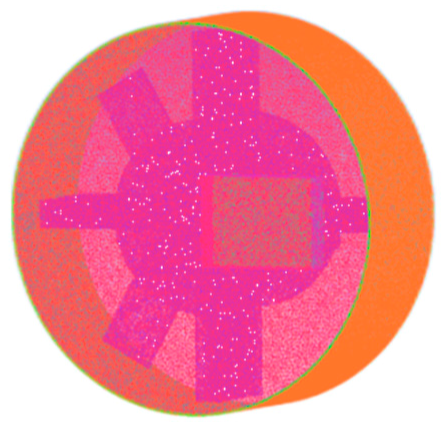
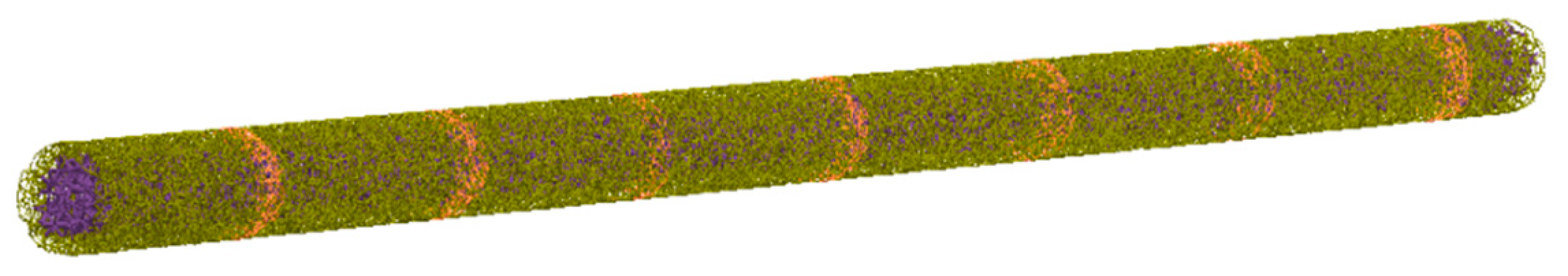
The corn straw model was established through the use of EDEM 2018 software, and three kinds of particles were filled inward, representing the outer skin, inner pulp, and node of the corn straw. The Hertz–Mindlin with Bonding model was selected as the particle contact mechanics model, according to the preliminary research of the subject group [
24,
25]. The model parameters are set as shown in
Table 2. The numerical simulation model of the corn straw and the schematic diagram of the bonds are shown in
Figure 8 and
Figure 9. The position coordinates of the three particles were derived separately for subsequent API particle replacement.
In this study, 101 single-sphere particles with a radius of 10 mm were utilized to superimpose the large particle model of corn straw. The mesh file of the simplified hammer mill model was imported into EDEM 2018 software, the particle-to-particle contact model was set to be the Hertz–Mindlin with Bonding model, and the contact model between the particles and the geometry was set to be the Hertz–Mindlin (no slip) model. The four file paths of the contact model, particle body force, particle, and factory, were replaced with 3 API program files of the outer skin, inner pulp, and node to complete the particle replacement, as shown in
Figure 10.
2.5.3. Fluent Parameter Setting
Ansys Fluent 17.0 software was applied to read the ICEM delineated mesh file, the pressure steady state solver was selected for numerical simulation calculations, the standard k-ε model was selected for the computational model, and the material was air. The feed inlet was defined as the speed inlet, the screen sheet was defined as the stationary wall, the rotor combination parts were defined as the moving wall, the speed was added, and the outer surface of the screen sheet was defined as the pressure outlet. SIMPLE was selected for the solution method, PRESTO! According to the preliminary research of the subject group [
26,
27], the format was selected for the pressure gradient, and the boundary conditions were set, as shown in
Table 3.
2.5.4. Coupling Link Settings
To ensure the efficiency of numerical simulation and maintain the coupling stability, it was necessary to set the time steps of the two software and the interval of data storage times as an integer multiple. The specific settings are shown in
Table 4.
2.6. Performance Evaluation of the Hammer Mill
To accurately evaluate the grinding performance of the hammer mill, refer to the national standard: GB/T6971-2007 [
28]. The test process is shown in
Figure 11. This study used per kW·h yield and the grinding pass rate as the evaluation indexes of the straw grinding performance test:
The hammer mill consumes the quality of corn straw ground by 1 degree of electricity.
where
Z is the per kW·h yield, (kg/(kW·h));
Qc is the quality of the corn straw ground during the working time of the grinder, (kg); and
Zc is the power consumption during the working hours of the mill, (kW·h).
where
S is the grinding pass rate, (%);
z1 is the quality of the qualified corn straw in the sample, (kg); and
z2 is sample quality, (kg).
Three people completed the test, and one controlled the frequency converter to adjust the spindle speed. Another one operated the computer, and M400 data acquisition and management software were used to record the spindle torque, speed, and power data and store them on the computer’s hard disk. The last one fed the corn straw to the grinding chamber corresponding to the test number and received the sample at the discharge port. After each test, 100 g was taken and stored in a sealed bag after sampling. At the same time, the test number was marked on a sealed bag for the subsequent calculation of electricity output and the grinding pass rate. The test process is shown in
Figure 11.
3. Results
3.1. Numerical Simulation Results and Analysis
3.1.1. Analysis of Flow Field Velocity in Grinding Chamber
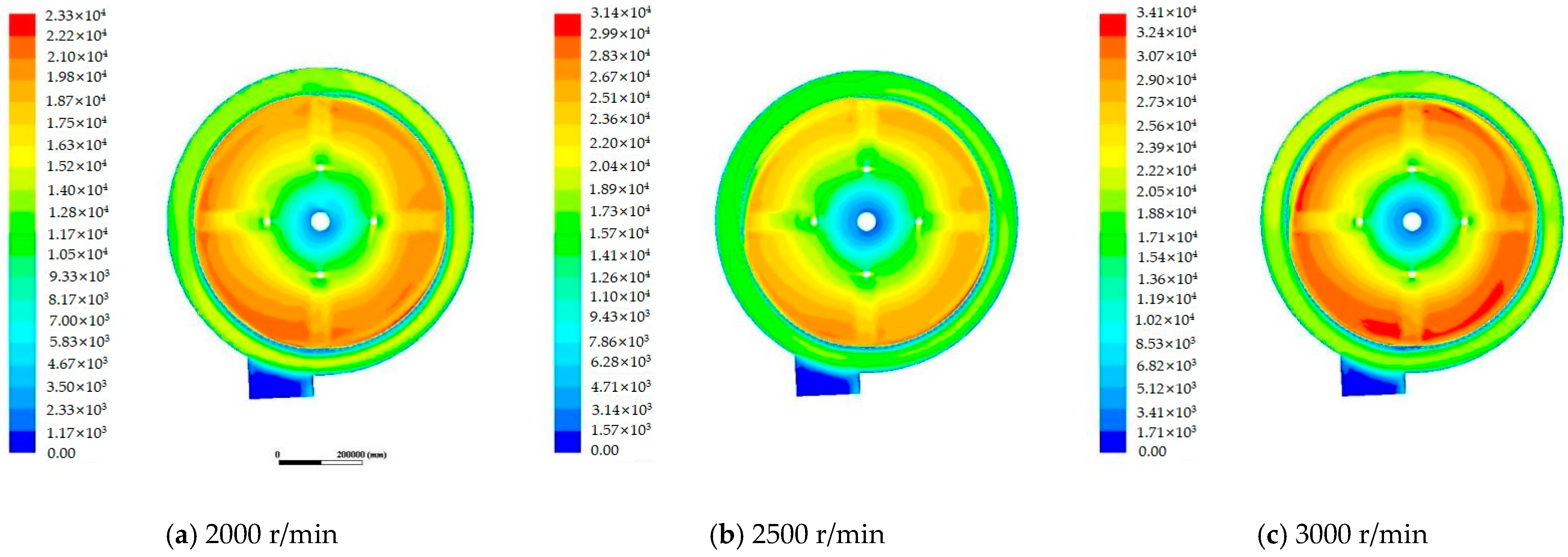
The velocity cloud diagram of the flow field inside the grinding chamber at different spindle speeds is shown in
Figure 12, from which it can be seen that from the spindle to the end of the hammer, the velocity was distributed in a gradient and was more uniform. With the increase in spindle speed, the flow velocity at the end of the hammer showed an increasing trend. Among them, the minimum flow field velocity near the spindle was close to 0 m/s, and the flow field velocity at the end of the hammer was the highest. Too high of a flow field velocity would increase the movement speed of corn straw, thus reducing the number of times the feed was hit, affecting the grinding efficiency. Therefore, the appropriate flow field velocity is conducive to improving straw grinding efficiency and yield.
3.1.2. Analysis of Pressure Field in Grinding Chamber
The pressure field inside the grinding chamber at different spindle speeds is shown in
Figure 13, from which it can be seen that the pressure was distributed in a gradient and was more uniform from the spindle to the sieve. With the increased spindle speed, the flow field pressure inside the grinding chamber showed an increasing trend. Among them, the pressure near the spindle was the smallest, and the pressure near the sieve was the largest. The greater the pressure of the sieve, the easier the corn straw comes out of the sieve, and the appropriate flow field pressure is conducive to improving the feed-out of the sieve rate.
3.1.3. Analysis of Bonds
The degree of the fracture of the bonding key used to connect the discrete elemental particle model of corn straw can simulate the natural grinding effect of corn straw. Therefore, the fracture characteristics of the bonds were analyzed for the numerical simulation of the corn straw grinding process. When the spindle speed was 2000 r/min, 2500 r/min, and 3000 r/min, respectively, the results of the number of broken bonds of the outer skin, inner pulp, and node with the spindle speed were studied, as shown in
Figure 14. From the diagram, it can be seen that with the increase in time, the higher the spindle speed, the faster the speed of breaking the bonds between the outer skin, inner pulp, and node particles, and the higher the grinding efficiency.
3.1.4. Analysis of Energy Losses in Hammer Components
The simulation results concerning the energy losses of the hammer components were analyzed by applying the EDEM post-processing part to derive the results of the total energy loss in the collision process between the hammer components and the corn straw. In this study, 100 data points were extracted from the analysis of 1 s in the continuous feeding process. The energy loss of the hammer components and the particle collision of each analysis data point were accumulated, and the energy loss results of the hammer of the 100 data points were added. The average value was taken three times to obtain the energy loss of the hammer components when the discrete element numerical simulation was 1 s. The results of the analysis are shown in
Figure 15,
Figure 16 and
Figure 17.
According to the analysis of the results in
Figure 15, the energy losses of the hammer components showed a growth–decrease–growth trend with increased spindle speeds. The higher spindle speed led to a higher linear velocity at the end of the hammer, which increased the impact force of the hammers on the straw, increased the number of times the straw was struck, and resulted in energy waste, leading to a high percentage of over-ground corn straw after processing. Therefore, it is necessary to reduce the spindle speed appropriately. According to the pre-grinding performance single-factor test results, when the spindle speed was 2500~2700 r/min, the grinding effect was better, and the per kW·h yield was higher. Therefore, to ensure the per kW·h yield, the spindle speed should be no higher than 2700 r/min, and the energy loss of the hammer components should be no higher than 1290.1 J.
According to the analysis of the results in
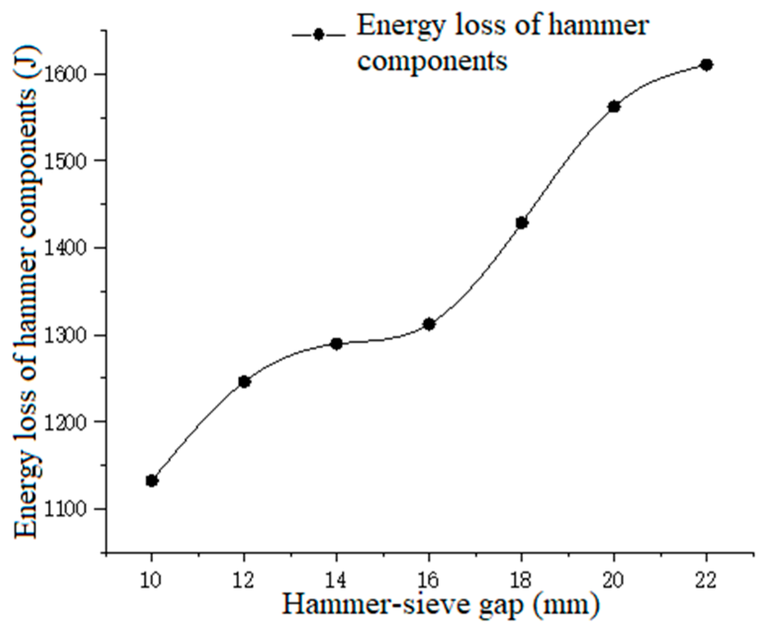
Figure 16, it can be seen that with the increase in hammer–sieve gap, the energy loss of the hammer components shows a growing trend. When the hammer–sieve gap is large, the hammer length is small, decreasing the contact area between the hammer and the corn straw. Corn straw must be struck many times before being ground into qualified feed and discharged from the machine, thus consuming additional energy and increasing the energy loss of the hammer components. According to the pre-grinding performance single-factor test results, when the hammer–sieve gap was 12~16 mm, the grinding effect was better, and the per kW·h yield was higher. Therefore, the energy loss of the hammer components should not be higher than 1312.2 J.
According to the analysis of the results in
Figure 17, the energy loss of the hammer components showed a decreasing trend with the increase in sieve pore diameter. The corn straw feed did not quickly come out when the sieve pore diameter was small. This led to feed with the qualified particle size being hit repeatedly, increasing the mass proportion of unqualified feed and causing energy waste. Therefore, it is necessary to increase the sieve pore diameter to ensure the efficiency of sieving, and the energy loss of the hammer components should be more than 985.6 J.
Based on the above results, it can be concluded that when the energy loss of the hammer components is 985.6~1312.2 J, the grinding effect is better, and the per kW·h yield is higher.
3.1.5. Analysis of Corn Straw Collision Force
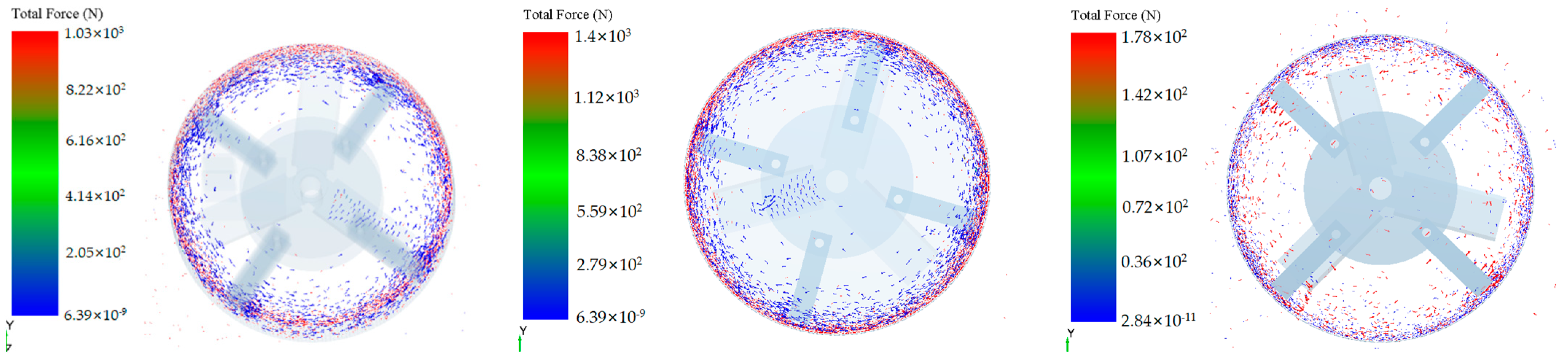
The collision force between the corn straw and the hammer components can reflect the grinding effect when the collision force reaches a certain degree to grind the straw, and the larger the collision force, the higher the grinding efficiency. According to the grinding performance test, the spindle speed had a more significant effect on the grinding effect of corn straw; therefore, spindle speed was used as a test factor to analyze the collision force of corn straw, as shown in
Figure 18, which shows the force diagrams of corn straw at the 5th s under different spindle speeds.
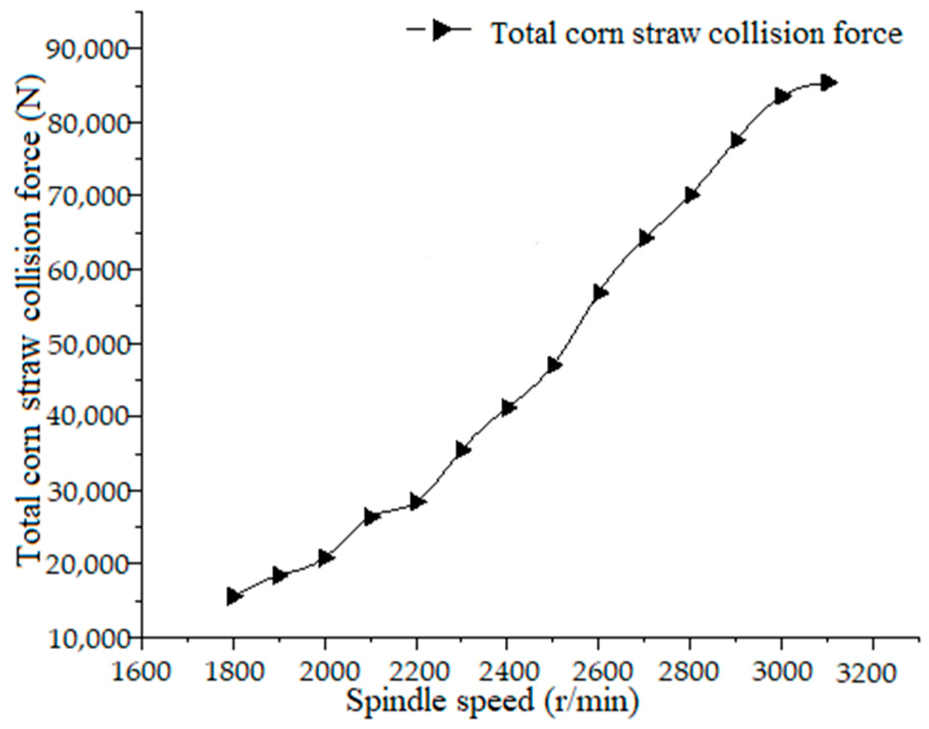
In the numerical simulation calculation, the running time was set to 5 s, and the storage time interval was set to 0.01 s. The discrete element numerical simulation of corn straw was selected to simulate all the particles, and the continuous feeding of 1 s was taken for analysis. A total of 100 data points were extracted. The collision force of corn straw at each time data point was accumulated, and then the collision force of 100 data points was added. Finally, the total collision force of corn straw was obtained. The collision force of the corn straw changes with spindle speed, as shown in
Figure 19.
According to the results of the pre-grinding performance single-factor test analysis, the grinding effect was better when the spindle speed was more than 2500 r/min. In the numerical simulation process, when the spindle speed was 2500 r/min, the total collision force of the corn straw was 47,032.5 N. Therefore, to ensure a better grinding effect, the total collision force of corn straw should be greater than 47,032.5 N.
3.2. Test Results
3.2.1. The Influence of Various Factors on the Performance of the Hammer Mill
According to
Figure 20a, it can be seen that the per kW·h yield with the increase in spindle speed showed a trend of growth and then a decrease. When the spindle speed was 2600 r/min, the per kW·h yield was the highest. The grinding pass rate tended to increase and then decrease with the increase in spindle speed, and when the spindle speed was 2500 r/min, the per kW·h yield was the highest. Therefore, according to the analysis of the results, the degree of corn straw grinding is better when the spindle speed is 2500~2700 r/min.
According to
Figure 20b, the per kW·h yield tended to grow and then decrease with the increase in the hammer–sieve gap, and the per kW·h yield was the highest when the hammer–sieve gap was 14 mm. The grinding pass rate grew with the increase in the hammer–sieve gap. Therefore, according to the analysis of the results, the degree of corn straw grinding is better when the hammer–sieve gap is 12~16 mm.
According to
Figure 20c, the per kW·h yield tends to increase and decrease with the increase in sieve pore diameter. The per kW·h yield was the highest when the sieve pore diameter was 8 mm. The grinding pass rate showed an increasing and then decreasing trend with the increase in sieve pore diameter, and it was the highest when the sieve pore diameter was 10 mm. Therefore, according to the analysis of the results, the degree of corn straw grinding is better when the sieve pore diameter is 6~10 mm.
3.2.2. Optimization of Working Parameters of Hammer Mill
Optimization of the working parameters can improve the working efficiency and service life of the machine, greatly reduce the production cost, and is also necessary for optimizing the structure of the machine [
29,
30,
31].
In order to make the hammer mill achieve the best working efficiency, this study used the Numerical function in Design-Export 10 data analysis software to optimize the per kW·h yield,
Z, and grinding pass rate,
S, as the double objective optimization. Then, parameter optimization was carried out in combination with the value range of each factor test to obtain a set of optimal working combination parameters, and the constraints are as follows:
where
A is the spindle speed, (r/min);
B is the hammer–sieve gap, (mm); and
C is the sieve pore diameter, (mm).
After optimization, the optimal working parameters of the hammer mill were obtained as follows: a spindle speed of 2625 r/min, a hammer–sieve gap of 14 mm, and a sieve pore diameter of 8 mm. According to the optimized working parameters, the grinding performance test was carried out again, and the test was repeated three times to take the average value. The test results showed that the per kW·h yield was 36.85 kg/(kW·h), and the grinding pass rate was 76.56%.
3.2.3. Numerical Simulation Verification Test
Based on the combined optimized working parameters, CFD–DEM gas–solid coupling numerical simulation calculation was carried out, and the simulation was repeated three times to obtain the average value. The results showed that the energy loss of the hammer was 1189.5 J, and the total collision force of corn straw was 49,523.5 N. Both values were within the range of optimal numerical simulation results, which verified the accuracy of the gas–solid coupling numerical simulation.
4. Discussion
This study established a discrete elemental model of corn straw containing nodes, and the corn straw grinding process was numerically simulated based on the CFD–DEM gas–solid coupling method. Cao et al. [
32] used Fluent software to numerically simulate the airflow field in the grinding chamber of the mill. The results showed that the negative pressure in the grinding chamber increased with the increasing speed of the mill. Zhang et al. [
25] used EDEM 2016 software to numerically simulate the movement process of the straw group in the grinding chamber. They obtained the motion law of the straw group at different speeds. All of the above scholars used the single-phase flow method for research. Based on their research, through theoretical analysis, we have determined that airflow has a particular influence on the straw grinding effect. Therefore, the gas–solid two-phase flow is used for research focusing closer on the actual grinding process.
Most scholars have established corn straw models. Zhang et al. [
33] established a corn straw discrete element model based on the BPM contact model, which significantly improved the bond strength of the model. Liu et al. [
34] established a bimodal distribution model of a double-layer bonding of corn straw using the discrete element method, which distinguishes between the outer skin and the inner flesh of the straw. The results showed that the uniaxial compression test was comparable with the simulation test. The results showed that the model is more accurate than the single-layer corn straw model. Based on the above research, due to the difference between the mechanical properties of the node, outer skin, and inner pulp of straw, we established a discrete element model for corn straw containing the node. The model is more in line with real corn straw and improves the authenticity and accuracy of numerical simulations.
The corn straw also includes bracts, sheaths, and other parts. Exploring its mechanical properties, obtaining contact parameters, and establishing numerical simulation models to ensure further improvement of the authenticity and accuracy of numerical simulation are the focus of the next step.
5. Conclusions
In this study, the CPS-420 hammer mill was used as a test prototype. The corn straw grinding process in the grinding chamber was studied through the use of theoretical analysis, discrete element simulation, and experiments. The results showed the following:
The theoretical analysis results showed that according to the force equation, as well as the differential equation of motion, it could be concluded that the key factors affecting grinding performance were spindle speed, hammer–sieve gap, and sieve pore diameter.
The numerical simulation results showed that with the increase in time, the higher the spindle speed, the faster the fracture of each part of the bonds, and the higher the grinding efficiency when the energy loss of the hammer components was 985.6~1312.2 J, and the total collision force of corn straw was greater than 47,032.5 N, the straw grinding effect was better. The per kW·h yield was higher.
The results of the grinding performance test showed that when the spindle speed was 2500~2700 r/min, the hammer–sieve gap was 12~16 mm, and the sieve pore diameter was 6~10 mm, the per kW·h yield was higher, and the grinding degree was better. After optimizing the working parameters, the optimal working parameter combination was obtained: a spindle speed of 2625 r/min, a hammer–sieve gap of 14 mm, and a sieve pore diameter of 8 mm. Based on the optimal working parameter combination, the grinding performance test results were as follows: the per kW·h yield was 36.85 kg/(kW·h), and the grinding pass rate was 76.56%. Finally, the CFD–DEM gas–solid coupling numerical simulation validation tests combined the optimal working parameter combinations. The results showed that the energy loss of the hammer components was 1189.5 J, and the total collision force of corn straw was 49,523.5 N. Both values were within the range of the optimal numerical simulation results, which verified the accuracy of the CFD–DEM gas–solid coupling numerical simulation of the corn straw grinding process.
Author Contributions
Conceptualization, X.W. and H.T. methodology, X.W. and H.T.; software, X.W.; validation, X.W.; formal analysis, X.W., Z.X., D.W. and D.L.; investigation, X.W.; resources, X.W.; data curation, X.W.; writing—original draft preparation, X.W.; writing—review and editing, X.W., H.T., K.Z., D.W. and D.L.; supervision, H.T.; funding acquisition, H.T. All authors have read and agreed to the published version of the manuscript.
Funding
This work was supported by The National Natural Science Foundation of China (52365035) and the Science and Technology Program Project of Inner Mongolia Autonomous Region (2022YFDZ0024) and the National Natural Science Foundation of China (32071893), and Innovation and Entrepreneurship Training Program for College Students at Inner Mongolia Agricultural University (202310129084).
Data Availability Statement
The data provided in this study are available upon request from the corresponding author.
Conflicts of Interest
The authors declare no conflicts of interest.
References
- Zhou, N.Y. Economic status and future prospects of China’s feed industry. China Feed 2020, 664, 128–131. [Google Scholar]
- Wang, Y.Q.; Zhang, H.G.; Meng, H.B.; Liu, W.W. Promotion and application of corn straw feed technology. China Anim. Health 2023, 25, 73–74. [Google Scholar]
- Zhang, X.L. Analysis of the application of crop straw feed in breeding. J. Smart Agric. 2022, 2, 63–64. [Google Scholar] [CrossRef]
- Liu, T.L.; Zhao, L.X.; Meng, H.B. Research and optimization of evaluation methods for straw energy utilization technology. Environ. Eng. 2020, 38, 195–200. [Google Scholar]
- Wondra, K.J.; Hancock, J.D.; Behnke, K.C.; Hines, R.H.; Stark, C.R. Effects of particle-size and pelleting on growth-performance, nutrient digestibility, and stomach morphology in finishing pigs. J. Anim. Sci. 1995, 73, 757–763. [Google Scholar] [CrossRef]
- Röhe, I.; Ruhnke, I.; Knorr, F.; Mader, A.; Boroojeni, F.G.; Löwe, R.; Zentek, J. Effects of grinding method, particle size, and physical form of the diet on gastrointestinal morphology and jejunal glucose transport in laying hens. Poult. Sci. 2014, 93, 2060–2068. [Google Scholar] [CrossRef]
- Wang, D.; He, C.B.; Tian, H.Q.; Liu, F.; Zhang, T.; Zhang, H.Q. Parameter optimization and experimental research on the hammer mill. INMATEH-Agric. Eng. 2020, 62, 341–350. [Google Scholar] [CrossRef]
- Tian, H.Q.; Wang, H.Q.; Huang, T.; Wang, D.; Liu, F.; Han, B.S. Design of combination sieve for hammer feed mill to improve crushing performance. Trans. Chin. Soc. Agric. Eng. 2018, 34, 45–52. [Google Scholar]
- Zeng, Z.W.; Ma, X.; Cao, X.L.; Zehua, L.I.; Xicheng, W. Critical Review of Applications of Discrete Element Method in Agricultural Engineering. Trans. Chin. Soc. Agric. Mach. 2021, 52, 1–20. [Google Scholar]
- Li, X.Q. The Stimulation of Maize Crushing by Hammer Mill and the Test of Hammer Performance Based on Discrete Element Method. Master’s Thesis, Inner Mongolia Agricultural University, Hohhot, China, 2020. [Google Scholar]
- Bian, X.L.; Hou, Y.J.; Zhao, M.; Yang, Y.Y. DEM and its application to particle pulverization. Min. Mach. 2015, 43, 62–67. [Google Scholar]
- Jiménez-Herrera, N.; Barrios, G.K.P.; Tavares, L.M. Comparison of breakage models in DEM in simulating impact on particle beds. Adv. Powder Technol. 2017, 29, 692. [Google Scholar] [CrossRef]
- Weerasekara, N.S.; Powell, M.S.; Cleary, P.W.; Tavares, L.M.; Evertsson, M.; Morrison, R.D.; Quist, J.; Carvalho, R.M. The contribution of DEM to the science of comminution. Powder Technol. 2013, 248, 3–24. [Google Scholar] [CrossRef]
- Xu, Y.; Zhang, X.; Wu, S.; Chen, C.; Wang, J.; Yuan, S.; Chen, B.; Li, P.; Xu, R. Numerical simulation of particle motion at cucumber straw grinding process based on EDEM. Int. J. Agric. Biol. Eng. 2020, 13, 227–235. [Google Scholar] [CrossRef]
- Naik, S.; Chaudhuri, B. Investigating granular milling in a hammer mill: Experiments and simulation. Wit. Trans. Model. Simul. 2011, 15, 121–132. [Google Scholar]
- Shi, Y.; Xin, S.; Wang, X.; Hu, Z.; Newman, D.; Ding, W. Numerical simulation and field tests of minimum-tillage planter with straw smashing and strip laying based on EDEM software. Comput. Electron. Agric. 2019, 166, 105021. [Google Scholar] [CrossRef]
- Pei, G.; Zhai, Z.P.; Lan, Y.Z.; Shi, S.C. Analysis of Coupling Motion Characteristics of Material and Air Flow in Multi-function Forage Kneading Machine. Trans. Chin. Soc. Agric. Mach. 2023, 54 (Suppl. S2), 156–163. [Google Scholar]
- Gu, F.W.; Zhao, Y.Q.; Wu, F.; Hu, Z.C.; Shi, L.L. Simulation analysis and experimental validation of conveying device in uniform rushed straw throwing and seed-sowing Machines using CFD-DEM coupled approach. Comput. Electron. Agric. 2022, 193, 106720. [Google Scholar]
- Han, D.D.; Zhang, D.X.; Yang, L.; Tao, C.; Youqiang, D.; Xiaohui, B. Optimization and Experiment of Inside-filling Air-blowing Seed Metering Device Based on EDEM-CFD. Trans. Chin. Soc. Agric. Mach. 2017, 48, 43–51. [Google Scholar]
- Cao, L.; Zhang, Y.; Zhang, Y.; Li, Y. Influence of screen parameters optimization on screening efficiency of feed hammer mill. Trans. Chin. Soc. Agric. Eng. 2016, 32, 284–288. [Google Scholar]
- Li, Q. Research on Improving the Screening Efficiency of Hammer Mill. Master’s Thesis, Inner Mongolia University of Science & Technology, Hohhot, China, 2020. [Google Scholar]
- Hirohisa, T.; Hideya, N.; Tomohiro, I.; Watano, S. Numerical modeling of fluid and particle behaviors in impact pulverizer. Powder Technol. 2012, 217, 148–156. [Google Scholar]
- Jayasundara, C.T.; Yang, R.Y.; Guo, B.Y.; Yu, A.B.; Govender, I.; Mainza, A.; van der Westhuizen, A.; Rubenstein, J. CFD-DEM modeling of particle flow in IsaMills-Comparison between simulations and PEPT measurements. Miner. Eng. 2011, 24, 181–187. [Google Scholar] [CrossRef]
- Wang, X.; Tian, H.Q.; Xiao, Z.Q.; Li, D.P.; Ren, X.G.; Cheng, X.; Liu, F. Determination of physical parameters of corn straw stem node contact and calibration of discrete element numerical simulation. Jiangsu Agric. Sci. 2023, 51, 162–170. [Google Scholar] [CrossRef]
- Zhang, T.; Liu, F.; Zhao, M.Q.; Ma, Q.; Fan, Q.; Yan, P. Moving Law of Straw Groups with Different Rotating Speed Based on Discrete Element Method. J. Agric. Mech. Res. 2018, 40, 195–199. [Google Scholar] [CrossRef]
- Wang, D. Study on Formation Mechanism of Benign Gas-Solid Flow Field and Sieve Structure Optimization of Hammer Mill. Ph.D. Thesis, Inner Mongolia Agricultural University, Hohhot, China, 2022. [Google Scholar]
- Wang, H.Q. Flow Field Analysis and Performance Experiment Study on Hammer Feed Mill. Master’s Thesis, Inner Mongolia Agricultural University, Hohhot, China, 2019. [Google Scholar]
- GB/T 6971-2007; Test Method for Feed Mills. The State Administration of Quality Supervision, Inspection and Quarantine of the People’s Republic of China China National Standardization Management Committee: Beijing, China, 2007.
- Fei, Q.; Zhao, W.Y.; Dai, F.; Li, L.L. Combined plate-tooth threshing device based on BP neural network and genetic algorithm Parameter optimization. Jiangsu Agric. Sci. 2014, 42, 351–354. [Google Scholar] [CrossRef]
- Chen, W.X.; Tai, J.B.; Chen, Z.C.; Liu, Y.; Zheng, S.H. Design and parameter optimization of trenching and soil-throwing blade for ecological tea garden by discrete element method. J. Fujian Agric. For. Univ. (Nat. Sci. Ed.) 2024, 53, 136–144. [Google Scholar] [CrossRef]
- Wang, Z.; Zhao, W.Y.; Shi, L.R.; Sun, B.G.; Sun, W.; Dai, F.; Zhou, G.; Guo, J.H.; Rao, G.; Li, H. Optimization of the motion parameters of a rolling spoon type precision hole planter based on DEM-MBD coupling. J. China Agric. Univ. 2024, 29, 66–77. [Google Scholar]
- Cao, L.Y.; Shi, X.H.; Shi, W.; Pei, Y.W. Simulation and Analysis on Flow Field in Crashing Cavity of New-type Feed Hammer Mill. J. Agric. Mech. Res. 2017, 39, 22–26. [Google Scholar] [CrossRef]
- Zhang, F.W.; Song, X.F.; Zhang, X.K.; Zhang, F.Y.; Wei, W.C.; Dai, F. Simulation and experiment on mechanical characteristics of kneading and crushing process of corn straw. Trans. Chin. Soc. Agric. Eng. 2019, 35, 58–65. [Google Scholar]
- Liu, Y.C.; Zhang, F.W.; Song, X.F.; Wang, F.; Zhang, F.Y.; Li, X.Z.; Cao, X.Q. Study on mechanical properties for corn straw of double-layer bonding model based on discrete element method. J. Northeast. Agric. Univ. 2022, 53, 45–54. [Google Scholar] [CrossRef]
Figure 1.
Three-dimensional model and sample machine of CPS-420 hammer mill: 1. upper feeding hopper; 2. sieve; 3. lower feeding hopper; 4. straw knife; 5. outlet; 6. frame; 7. hammer; 8. motor.
Figure 1.
Three-dimensional model and sample machine of CPS-420 hammer mill: 1. upper feeding hopper; 2. sieve; 3. lower feeding hopper; 4. straw knife; 5. outlet; 6. frame; 7. hammer; 8. motor.
Figure 2.
Corn straw grinding process. (The location and grinding of the straw marked by the red square).
Figure 2.
Corn straw grinding process. (The location and grinding of the straw marked by the red square).
Figure 3.
Stress analysis diagram of corn straw.
Figure 3.
Stress analysis diagram of corn straw.
Figure 4.
Motion analysis diagram of the corn straw unit.
Figure 4.
Motion analysis diagram of the corn straw unit.
Figure 5.
Force analysis diagram of the corn straw unit.
Figure 5.
Force analysis diagram of the corn straw unit.
Figure 6.
Simplified model.
Figure 6.
Simplified model.
Figure 8.
Numerical simulation model of corn straw: 1. inner pulp particles; 2. node particles; 3. outer skin particles.
Figure 8.
Numerical simulation model of corn straw: 1. inner pulp particles; 2. node particles; 3. outer skin particles.
Figure 9.
Diagram of bonds.
Figure 9.
Diagram of bonds.
Figure 10.
Particle replacement.
Figure 10.
Particle replacement.
Figure 12.
Velocity variation in the flow field inside the grinding chamber at different spindle speeds.
Figure 12.
Velocity variation in the flow field inside the grinding chamber at different spindle speeds.
Figure 13.
Variation in pressure field inside the grinding chamber at different spindle speeds.
Figure 13.
Variation in pressure field inside the grinding chamber at different spindle speeds.
Figure 14.
The results of different spindle speeds on the number of bonds over time.
Figure 14.
The results of different spindle speeds on the number of bonds over time.
Figure 15.
The results of the variation in the energy loss of the hammer components with spindle speeds.
Figure 15.
The results of the variation in the energy loss of the hammer components with spindle speeds.
Figure 16.
The results of the variation in the energy loss of the hammer components with the hammer–sieve gap.
Figure 16.
The results of the variation in the energy loss of the hammer components with the hammer–sieve gap.
Figure 17.
The results of the energy loss of the hammer components with the change in sieve pore diameter.
Figure 17.
The results of the energy loss of the hammer components with the change in sieve pore diameter.
Figure 18.
The vector diagram of straw collision force at different spindle speeds.
Figure 18.
The vector diagram of straw collision force at different spindle speeds.
Figure 19.
Numerical simulation results of straw collision force variation with spindle speeds.
Figure 19.
Numerical simulation results of straw collision force variation with spindle speeds.
Table 1.
The main technical parameters of the CPS-420 hammer mill.
Table 1.
The main technical parameters of the CPS-420 hammer mill.
| Parameter | Value |
|---|
| Size (length × width × height) | 850 mm × 800 mm × 1300 mm |
| Grinding chamber diameter | 420 mm |
| Grinding chamber width | 180 mm |
| Rotor diameter | 340 mm |
| Motor power | 3 kW |
| Hammer numbers | 16–24 |
| Machine capacity | 600–1000 kg/h |
Table 2.
Parameter settings of Hertz–Mindlin with bonding model.
Table 2.
Parameter settings of Hertz–Mindlin with bonding model.
| Parameter | Normal Stiffness (N/m3) | Shear Stiffness (N/m3) | Critical Normal
Stress (Pa) | Critical Shear
Stress (Pa) |
|---|
| Outer skin–Outer skin | 5.5 × 10⁹ | 5.2 × 10⁸ | 1.22 × 10⁸ | 7.89 × 10⁶ |
| Inner pulp–Inner pulp | 5.05 × 10⁸ | 5 × 10⁷ | 1.4 × 10⁶ | 3.9 × 10⁵ |
| Node–Node | 5.23 × 10⁸ | 4.89 × 10⁷ | 1.35 × 10⁶ | 3.88 × 10⁵ |
| Outer skin–Inner pulp | 5.05 × 10⁸ | 5 × 10⁷ | 1.4 × 10⁶ | 3.9 × 10⁵ |
| Outer skin–Node | 5.21 × 10⁸ | 5.02 × 10⁷ | 1.39 × 10⁶ | 3.68 × 10⁵ |
| Inner pulp–Node | 5.05 × 10⁸ | 5 × 10⁷ | 1.4 × 10⁶ | 3.9 × 10⁵ |
Table 3.
The setting of boundary conditions.
Table 3.
The setting of boundary conditions.
| Boundary Condition | Value |
|---|
| Inlet velocity | 10 m/s |
| Inlet turbulence intensity | 5% |
| Inlet hydraulic diameter | 108 mm |
| Outlet turbulence intensity | 5% |
| Outlet hydraulic diameter | 200 mm |
| Outlet pressure | 0 Pa |
Table 4.
EDEM–FLUENT coupling time step relationship.
Table 4.
EDEM–FLUENT coupling time step relationship.
| Software | Time Step (s) | Data Storage Time (s) |
|---|
| EDEM 2018 | 1.2 × 10⁻⁶ | 0.01 |
| FLUENT 17.0 | 1.2 × 10⁻⁴ | 0.1 |
| Disclaimer/Publisher’s Note: The statements, opinions and data contained in all publications are solely those of the individual author(s) and contributor(s) and not of MDPI and/or the editor(s). MDPI and/or the editor(s) disclaim responsibility for any injury to people or property resulting from any ideas, methods, instructions or products referred to in the content. |
© 2024 by the authors. Licensee MDPI, Basel, Switzerland. This article is an open access article distributed under the terms and conditions of the Creative Commons Attribution (CC BY) license (https://creativecommons.org/licenses/by/4.0/).


