Article

Application of Geographic Information System and Automated Guidance System in Optimizing Contour and Terrace Farming

Department of Plant and Soil Science, Texas Tech University, Lubbock, TX 79409, USA
Agriculture 2018, 8(9), 142; https://doi.org/10.3390/agriculture8090142
Submission received: 21 August 2018 / Revised: 10 September 2018 / Accepted: 12 September 2018 / Published: 14 September 2018
(This article belongs to the Special Issue Advances in Agriculture Mechanization)

Abstract

:
Farming contour and terrace fields using automated guidance systems with global navigation satellite system (GNSS) receivers requires appropriate geographic features for effective guidance and soil and water conservation. The objective of this paper was to develop methodologies for improving and designing guidance features for operating guidance systems in contour and terrace fields. This study was conducted in the Texas High Plains where contour and terrace farming practices are prevalent in slope fields. Four case studies were used to demonstrate the application of a geographic information system (GIS) in optimizing guidance geographic features, including line smoothing, line extending and connecting, creating swath AB lines, and guide-to-line features. Line smoothing removes sharp angularities and curve oscillations on guidance line features, resulting in smooth and more effective guidance operations. The line extension and connection method creates a more convenient and simple guidance feature by combining multiple AB lines. Guide-to-line features derived from AB lines can eliminate confusions when using a guidance system with multiple AB lines in fields with complicated topographic attributes. A methodology was also developed to create guidance AB lines by processing the elevation data generated by a guidance system with a real-time kinematic (RTK) receiver. Guidance line features created in this study satisfy user requirements for effective guidance operations and soil and water conservation. Integrating the application of GIS spatial analysis capabilities and automated guidance systems can enhance farming operations by improving or creating guidance line features, as well as satisfying soil and water conservation needs. Parameter selection for enhancing or creating guidance line features needs to consider unique field conditions and user requirements for simple, convenient, and effective field operations.

1. Introduction

Contour and terrace farming practices are effective means of soil and water conservation in sloped fields. Contour farming changes the direction of runoff from directly downslope to around the hillslope by ridges and furrows formed by tillage, planting, and other farming operations. This practice reduces sheet and rill erosion, reduces transport of sediment or other solids, and increases water infiltration [1]. A terrace is a combination of ridges and channels constructed across the field slope to reduce erosion, trap sediment, and retain runoff for water conservation. Terraces can be constructed in fields in a manner that provides a suitable outlet for water. These fields should have the appropriate soils and topography that allow such construction with reasonable effort [2].
Contour and terrace farming practices are challenging because of the need to drive implements in complicated terrain with various row directions. The use of navigation guidance systems, especially those with real-time kinematic (RTK) global navigation satellite system (GNSS) receivers can significantly improve such operations. These guidance systems can automatically steer tractors and implements at centimeter accuracy, resulting in evenly spaced crop rows without guess rows. This improves farming efficiency, reduces fatigue, and saves fuel, time, and crop inputs, such as chemicals, fertilizer, and seed. These guidance systems can operate in low visibility and harsh weather, allowing timely operations especially during critical operations, such as planting and harvesting seasons. In addition, the position information from RTK GNSS guidance systems can be used for other applications such as seed mapping, controlled traffic, controlled tillage, digital terrain analysis, and terrace faming design [3,4]. Cultivation on contours in slope fields using RTK guidance systems can reduce the flow of water on soil, thereby controlling soil erosion, reducing stream sedimentation, and increasing water infiltration [5,6].
Automated guidance operations require the establishment of geographic line features using the on-board GNSS receiver and computer on the guidance system. These line features are usually called swath AB lines (A as the start and B as the end), and serve as guidance references for subsequent passes in the whole field or a portion of the field as designated by the operator. An AB line is created usually by first manually driving a guidance system following existing features in the field, such as crop rows, terrace or contour ridges, flags showing line positions, etc. During this process, the onboard computer records geographic positions in the driving path and converts these point positions to an AB line, a geographic line feature with two or more points or vertices. There are three major types of guidance line features: straight, circular, and freeform curves (Figure 1). For a straight AB line, only two points are required, i.e., the start point A and end point B. For a circular AB line, multiple points in addition to the center position are required. For a freeform line, in addition to points A and B, a certain number of points between these two points are required, depending on the complexity of the terrain and user requirements. When using the guidance system for field operations, such as planting, the guidance system with an implement is directed to any path at a multiple of a specified swath width from the swath AB line. For example, an eight-row planter 8.12 m wide (26.7 feet, 40-inch row spacing) will be directed to drive 24.36 m at the third path away from the AB line.
As shown in Figure 1, guidance operations in contour and terrace fields with freeform line features are more complex than with straight and circular lines. Furthermore, freeform AB lines generated from contour or terrace fields using guidance systems often have various defects that can cause challenges for subsequent guidance operations. Some AB lines may contain many sharp angularities to prevent smooth guidance. In some cases, unnecessary line segments are generated for guidance due to the geometric characteristics of the contours or terraces within the field. In other cases, guidance operations may have ambiguities at the intersections of AB lines with different orientations. These issues, if not corrected, will adversely affect future guidance farming operations. Optimized route and path planning is one of the most important requirements in farm management as a way to develop an advanced integrated fleet management [7], because route and path planning in agricultural fields are related to the amount of input costs, such as fuel, herbicides, and labor, as well as the consumed and associated soil compaction [8]. Therefore, optimizing guidance patterns can improve farming efficiency by planning paths using guidance lines [9]. A useful optimization algorithm should provide the capability of supporting the operator effectively in deciding on an optimum guidance pattern [10]. Geographic information systems (GIS) can be used to improve geographic guidance line features or optimize route designs. A GIS provides necessary functionality to capture, store, and query, as well as analyze geographic information and integrate different information sources to compliment practical management decisions [11,12]. The technology of GIS plays an increasingly important role in precision agriculture, especially in terms of the development of automated guidance of field operations, which requires the full integration of positioning, sensing, and control systems to allow both the guidance of field machinery and the control of field operations to be combined [12]. When optimizing field traffic patterns to improve machinery efficiency using guidance lines, various factors need to be considered, such as field size and shape, terrain, drainage characteristics, equipment size, etc. [9]. Research was conducted to optimize driving direction and route designs within fields with various geometrical shapes. For example, de Bruin [13] applied a GIS in optimizing the spatial configuration of cropped swaths within agricultural fields while creating space for field margins. Bochtis and Vougioukas [14] developed an algorithm to minimize the non-working distance traveled by agricultural machines operating in parallel tracks. Long et al. [6] proposed a strategy to reduce soil erosion in a contour field by designing planting patterns on the upper shoulder slope. This research also examined artificial neural networks for generating routing maps to optimize planting on precise, global positioning system (GPS)-guided contours. Hameed et al. [15] developed an algorithm to generate guidance lines for simple or complex fields with both convex and non-convex field boundaries, where generated line features could be straight or curved. Most of the current approaches primarily focus on reducing the traveled distances when optimizing paths or route designs [8]. These optimization algorithms are not directly applicable in contour and farming because they do not incorporate the requirements for soil and water conservation. A methodology [4] was developed to generate terrace guidance features, but it did not consider guidance feature optimizations for contour fields under various conditions. Therefore, the goal of this study was to present algorithms to optimize and generate geographic line features for automated-guidance field operations that integrate soil and water conservations in contour and terrace fields. Specifically, the objectives of this paper were to (1) develop algorithms to improve guidance features generated from guidance systems and optimize route designs for field operations; (2) develop methodologies to generate guidance features from spatial analysis of digital elevation data for soil and water conservation in contour and terrace farming.

2. Experiment and Materials
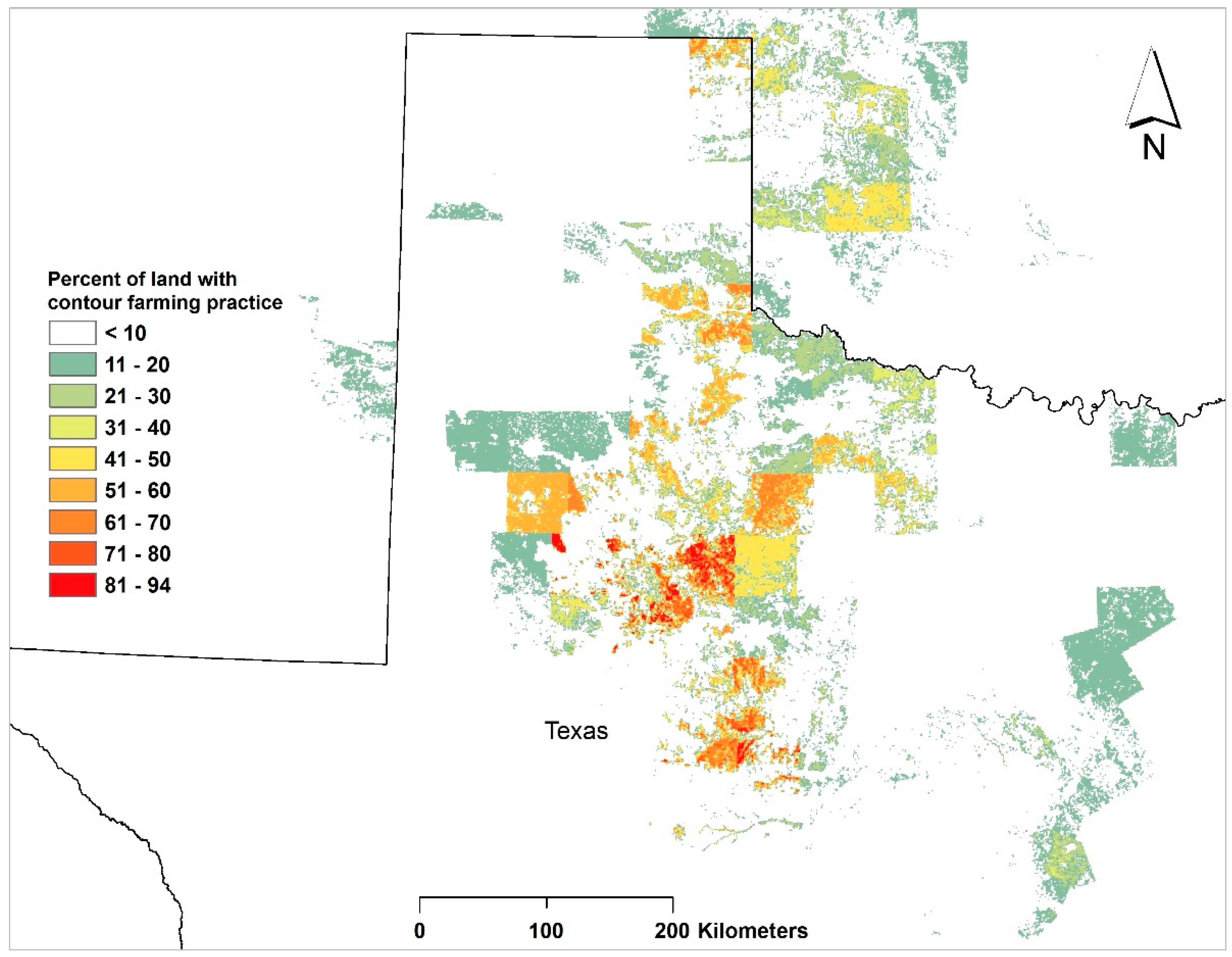
2.1. Study Area

The study was conducted in the Texas Plains region in northwest Texas, including the Texas High Plains (THP) and Texas Rolling Plains (TRP), where contour and terrace farming practices are common, especially in the TRP (Figure 2). The Southern High Plains is an extensive plateau covering about 130,000 km2 [16]. Contrary to the “flat” impression described by some literature, many fields have substantial topographic variations, especially in fields with playa lakes, where gentle to steep slopes usually exist surrounding these lakes. Agricultural production is intensive in this area, with major crops including upland cotton (Gossypium hirsutum L.), corn (Zea mays L.) grain sorghum (Sorghum bicolor (L.) Moench), and winter wheat (Triticum aestivum L.). Soils of this region are fine-textured, highly erodible sandy loams and clay loams [17]. The TRP is a gently rolling region containing rangelands and intensive agricultural production. Row crops grown in this region are mainly winter wheat, cotton, and grain sorghum. Production in the TRP is mainly dependent on seasonal precipitation. The Texas Plains region is mostly semi-arid, with variable precipitation and high evaporative demand [18]. As a result, water is generally the most limiting factor for crop production. Various technologies and practices are adopted in the Texas Plains region for soil and water conservation, including terracing and contour cultivation [19].

2.2. Equipment

A Trimble Autopilot guidance system (Trimble Navigation, Sunnyvale, CA, USA) was used in each of the following case studies. This system consists of two sets of dual-frequency GNSS receivers and radios, a steering sensor, a navigation controller, a control valve, and a computer unit. This automated guidance system applies the RTK survey principle for accurate positioning and guidance. The RTK survey determines relative positions between receivers simultaneously tracking the same GNSS satellites [21]. The positioning accuracy of an RTK GNSS receiver is 1 cm in horizontal directions and 2 cm in vertical directions [22]. In this method, one receiver remains stationary at a known location (base station) and the other receiver (rover) is set up within 10 km of the base station. The measurements and coordinates of the base receiver are transmitted to the rover receiver through a communications link (radio), which is attached to both the base and rover receivers [4]. During guidance operations, the navigation controller sends electrical instructions to the control valve using data from the steering sensor and GNSS receiver. The control valve then converts the instructions into hydraulic commands that the tractor’s steering system uses to track the guidance line features on the computer unit.
In this study, RTK GNSS signals were obtained from an RTK base station within 10 km of each study field. Tractors with guidance systems in the case studies varied, but the major components of the Trimble Autopilot system and guidance performance were the same.

2.3. Software

ArcGIS Desktop (ESRI, Version 9.3, Redland, CA, USA) was used for spatial data processing, guidance feature editing, and mapping. The Spatial Analyst extension to ArcGIS was used in digital elevation data processing, which involves interpolation and data format conversions between raster and vector data. Background images in the maps created in this study were from World Imagery (Source: Esri, DigitalGlobe, GeoEye, i-cubed, USDA FSA, USGS, AEX, Getmapping, Aerogrid, IGN, IGP, swisstopo, and the GIS User Community) as a basemap in the ArcGIS Online tool. A third-party add-on program to ArcGIS, the ET Geowizards (ET SpatialTechniques, Pretoria, South Africa) was applied in line feature smoothing.

3. Case Studies

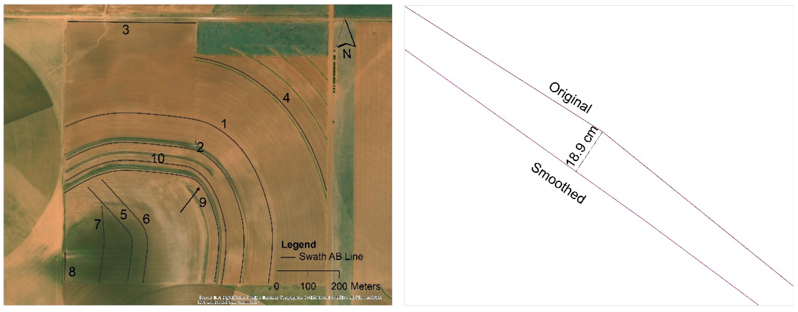
3.1. Case Study 1—Line Smoothing

Line smoothing is a technique to interpolate curve coordinates on a line, thereby smoothing and densifying the set of vertices that represents a line [23]. The smoothing process removes sharp angularities and attenuating curve oscillations. Smoothing changes the original shape, i.e., it alters the number and vertex coordinates on the line. For field operations using a guidance system, this alteration cannot change the general direction and shape of the curve. In addition, minimal alteration should be applied to segments that are already smooth. The B-spline method can meet these requirements. A B-spline is a smooth parametric curve defined by a polynomial expression. The continuous curve of a B-spline is defined by control points (vertices on a curve) and the user has a local control on the curve. In general, the curve only goes through the first and last control points although it is shaped by the control points [24]. When using the ET Geowizards program to smooth a line, two parameters, smoothness and freedom, have to be chosen. Smoothness is an integer that defines the number of points in the smoothed line. The number of vertices of the original line multiplied by this smoothness parameter gives the number of vertices of the smoothed line. A smoothed line with too many points will slow down the loading of line features to the computer system on board the guidance system. Thus, a general rule for smoothing is to minimize the number of points on a line to represent a smooth guidance line feature. Freedom is an integer that defines how close the new line is to the original line. The allowed values are from 2 to 10. Smaller values give better approximation (ET Geowizards User Guide). For smoothing these lines, a value of 5 was selected for the “smoothness” parameter, and a value of 3 was selected for the “freedom” parameter.
This study was conducted in a sloping field in Hockley County, Texas (Figure 3). Elevation in this field ranged from 1019.6 m to 1026.0 m, with highest position in the northeast corner and lowest in the southwest corner. Seven terraces with various lengths were constructed before this study. Ten swath AB lines were generated, two being straight (Line 3 and Line 8) and eight being freeform curves. Line 9 and Line 10 had some sharp angularities that needed smoothing.
As shown on Figure 3, the alteration measured by the distance from the smoothed line to the original line was up to 18.9 cm at sharp angularities, whereas at smooth segments, these alterations were generally less than 1 cm. Parameter values selected in this case study provided a smooth guidance line while preserving the original line direction and general curve shape. As a result, these guidance line features were established and they fit the user’s requirement for field operations. It should be advised that parameters selected in this study met the requirements in this field condition and the use requirements for guidance operation. Each field has unique topography and guidance lines created which only fit that field condition. Parameter selection (freedom and smoothness) for smoothing freeform AB lines of other fields needs to consider conditions and user requirements.

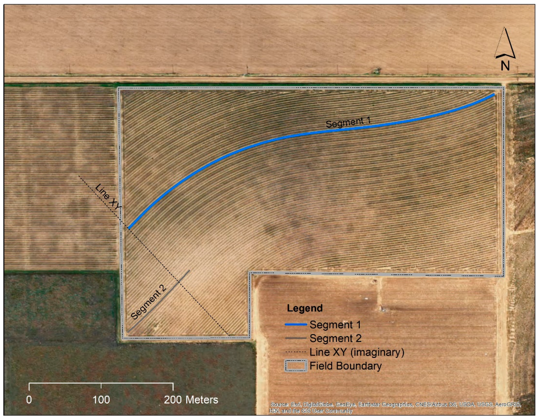
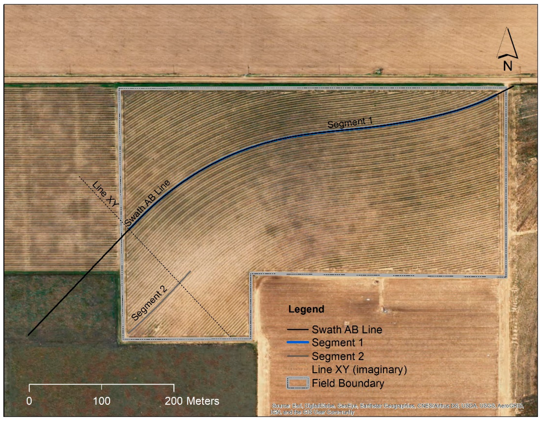
3.2. Case Study 2—Line Extension and Connection

Many contour or terrace fields have relatively simple topography and gentle slopes. However, in many cases, the unique combination of field orientation and slope directions requires multiple AB lines to cover guidance operations in the whole field. This creates inconveniences in a portion of the field where guidance paths in reference to two or more AB lines intersect. As illustrated in Figure 4, AB Line 1 (Segment 1) provides a guidance reference for the north side of the field. It also provides a guidance reference for the south side of the field, except the area to the left (west) of the imaginary Line XY. Another AB line, Segment 2, was created to cover guidance in that area, but it could not provide adequate guidance reference beyond the Line XY to the right (east). During guidance operations, switching from AB Line 1 (Segment 1) to AB Line 2 (Segment 2) in areas along the Line XY would create confusion and inconveniences. The objective of this case study was to develop a method to simplify guidance operation by combining multiple AB lines for guidance operations for the whole field.
This study was conducted in the aforementioned field in Lynn County, Texas. Elevation in this field ranged from 970.2 m to 972.6 m. Elevation gradually decreases from the south to the north side of the field. To combine the two AB lines, Segment 1 serves as the main part, and Segment 2 as its complement (Figure 5). Firstly, the vertical distance between Segment 1 and Segment 2 along Line XY was measured, which was 94.17 m. Segment 2 was then moved 94.17 m toward Segment 1 using the “Copy Parallel” function of the Editor toolset in ArcGIS. Segment 1 and Segment 2 were then merged using the “Merge” function in “Data Management Tools”. In the editing mode, vertices on Segment 1 to the left of Line XY and vertices on Segment 2 to the right of Line XY were removed to ensure end-to-end connection of Segment 1 and Segment 2. While in editing mode, snapping options were set to “End Snapping”. At Line XY, the last vertex on Segment 2 was dragged and snapped to the last vertex on Segment 1 to ensure that no gap or “overshoot” was created for the new line. This process created a new AB line with a slight angularity at the connection point between Segment 1 and Segment 2. This angularity was removed by smoothing the whole line using the ET Geowizards. This smoothing process is similar to that described in Case Study 1. The parameters “smoothness” and “freedom” were set to 2 and 3, respectively, to ensure a smooth line while minimizing alteration to conform to the original user requirement. Since the original Segment 2 was approximately a straight line, the vertices, except the end point to the left of Line XY, were removed to form a straight segment. As shown in Figure 5, the resultant new swath AB line consists of a straight segment (mostly outside of the field boundary) and a smooth curve to the right of Line XY. This new line was adequate for guidance in the whole field and was adopted for field operations. The line extension and connection method creates a more convenient and simple guidance feature by combining multiple AB lines for effective and guidance operations in fields with relatively simple topographic attributes.

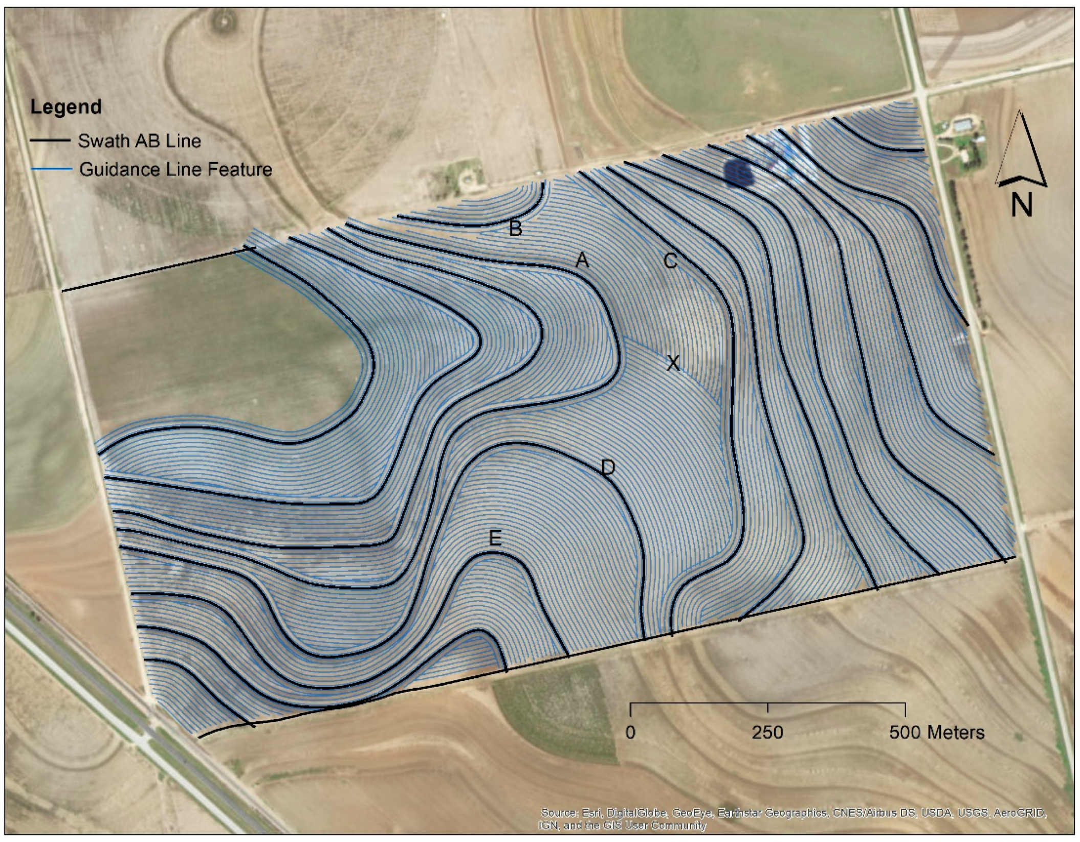
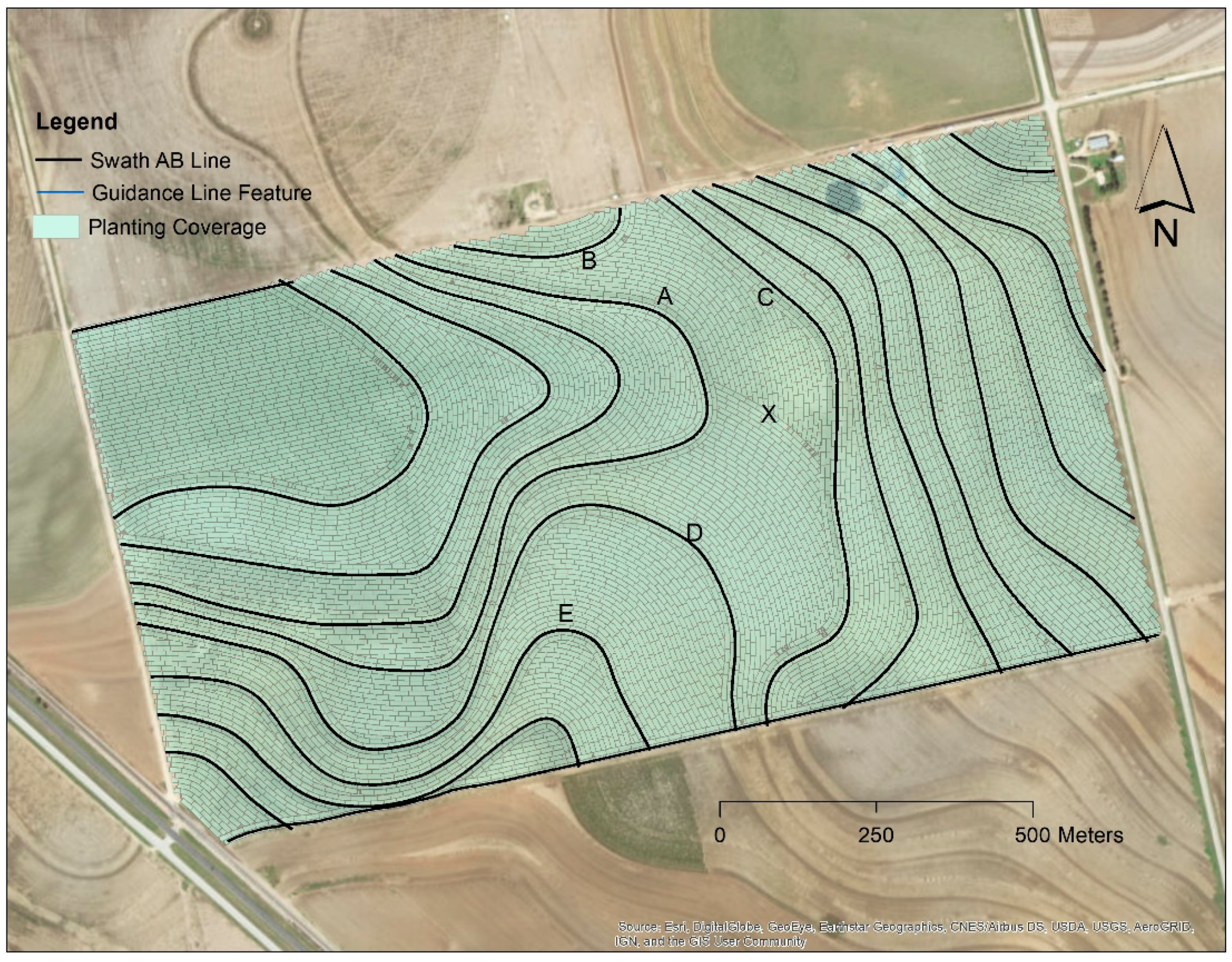
3.3. Case Study 3—Guide-to-Lines

Many contour fields are complicated in topography, such that separate parcels of land are generated for field management and operations. This often results in multiple AB lines for guidance operations in a single parcel (Figure 5). Field operations with the guidance system in between the swath AB lines in these parcels, however, may encounter confusions as to which AB line to choose for guidance, especially at locations away from any AB lines. For instance, guidance operation in the parcel between Lines A, B, C, and D is challenging because the user might be confused which line to use for guidance at position X. During a crop season, the operator must use the same AB line at a particular position relative to all the surrounding AB lines. The inconsistent use of AB lines at the same location may result in the implement crossing crop rows at wrong locations, causing crop damage especially during operations at night and in other low visibility conditions. The objective of this case study was to develop a method to create line features to eliminate confusions during guidance operations with multiple AB lines in the same field.
This study was conducted in the aforementioned field in Scurry County, Texas. Elevation in this field ranged from 731.0 m to 736.5 m. For soil and water conservation with the complex topography, 17 terraces with various lengths were constructed across the field before this study (Figure 6). A freeform swath AB line was created for each terrace by driving a Trimble Autopilot guidance system along each terrace ridge. The northwest part of the field has relatively flat topography; thus, a straight AB line was created along the field edge for guidance in that parcel. At the south edge of the field, a freeform AB line (not representing a terrace) was created for guidance on paths along the field boundary.
The land parcel between swath AB Lines A, B, C, and D was used to illustrate the generation and processing of guide-to-line features. An implement width needs to be chosen for such an operation before line feature creation. In this study, the implement width was 8.13 m (eight-row and 40-inch spacing), which is the most commonly used implement width for the user’s field operation. The “Copy Parallel” function in ArcGIS was used to create line features parallel to each swath AB line (Figure 7). For the first line next to each swath AB line, half of the implement width (4.07 m) was used as the distance parameter for copying the swath line. The distance parameter for subsequent lines next to the first lines was at a multiple of the full implement width (8.13 m) in addition to the first half-implement width. For instance, the distance parameter for the second path would be 12.20 m (sum of 4.07 m and 8.13 m). These distance intervals ensured that there were no gaps or skips between any paths in any field operations using this implement width. The total number of paths from each AB line is dependent on the user requirements. The general rule is to maximize field operation efficiency and simplicity. In this study, for swath AB Lines A, B, C, and D, the number of lines was 28, 2, 3, and 30, respectively. For the area below the location marked as X, only two paths from the AB line were kept. The portions of lines intersecting with the other lines were clipped off to avoid confusion during field operations. The same clipping process was applied to other lines generated. The same procedure was applied to other land parcels in the field. Guide-to-line features were not created for the northwest parcel, where the normal guidance to swath AB line was chosen for field operations. In total, 374 guide-to-line features were created for the whole field. Figure 8 shows polygon coverage recorded by a Trimble guidance system when using the designed guide-to-line features during planting. As demonstrated, there are minimal overlaps or skips in the operation. Confusions regarding which AB line to use for guidance were eliminated.
The Trimble Autopilot guidance system has two modes of guidance operations, i.e., swath AB line guidance and guide-to-line guidance. In the guide-to-line mode, the guidance system only engages on a specific line feature when the system approaches the closest guide-to-line feature. The operator does not have to choose which AB line to use during field operations. The system only engages on pre-planned line features. This eliminates confusion and provides consistent guidance within and among growing seasons, greatly improving field operation efficiencies. The advantage of the guide-to-line option is that it eliminates confusion and inconsistency at any location within a field. The disadvantage is that a separate set of guide-to-line features is required for each implement width. For instance, in this study, the guide-to-line features were only appropriate for an implement width of 8.13 m. Another implement width, for instance, one with 12 rows and 40-inch spacing, would require another set of guide-to-line features generated with the same procedure, but with another set of distance intervals.

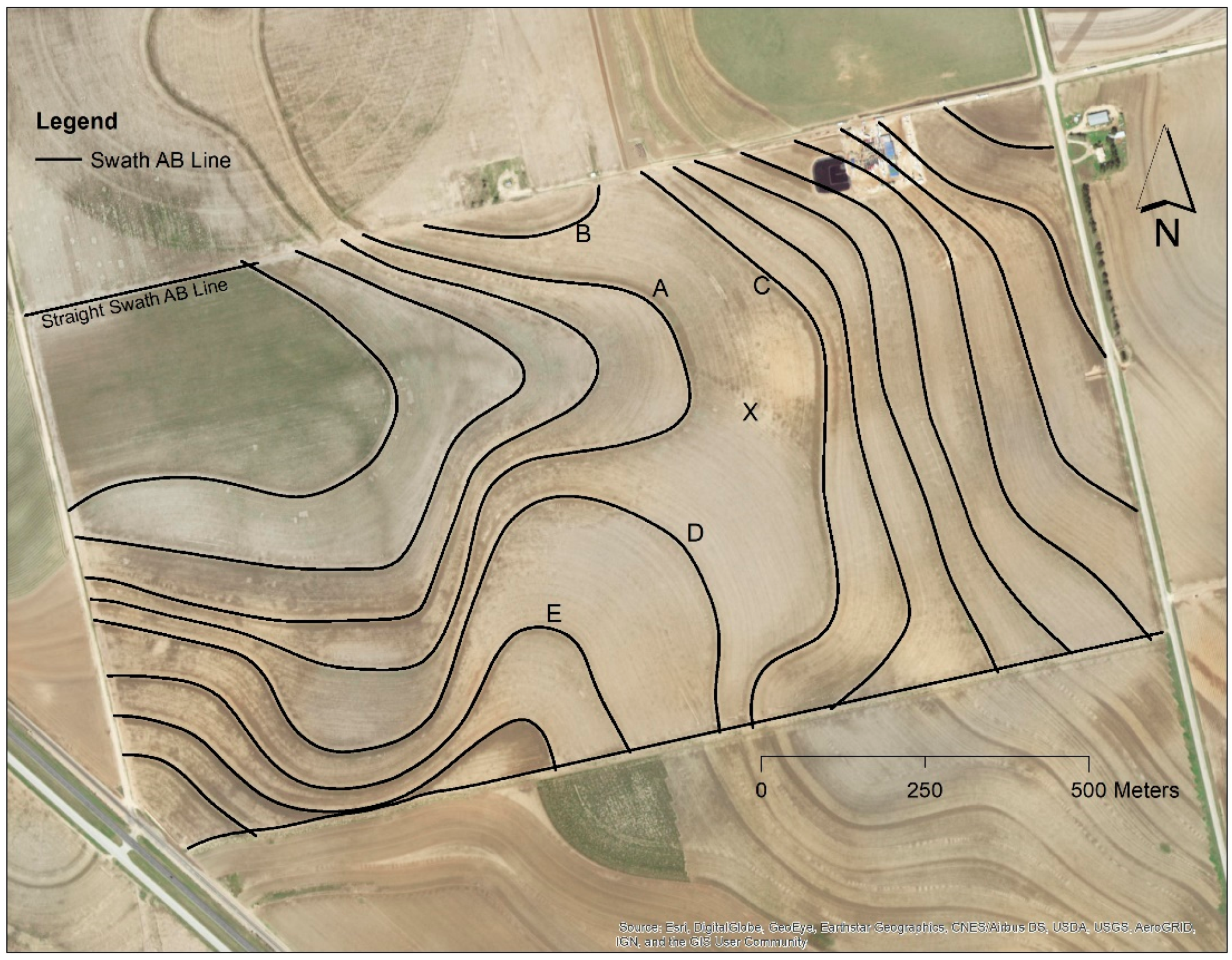
3.4. Case Study 4—Creating Guidance AB Lines

In some fields with significant slopes, contours or terraces are never established or constructed. There are no obvious features to follow to establish guidance AB lines. One important consideration when establishing guidance patterns is soil and water conservation. In contour farming, the row orientation follows the contour of the slope to prevent soil erosion. Surface water movement is slowed by the row ridges, allowing water to infiltrate instead of running off [19]. Therefore, it is highly desirable to incorporate soil and water conservation in the design of guidance line features. The RTK guidance system is an excellent tool for collecting spatial data containing latitude, longitude, and elevation. The elevation measurements recorded by the RTK system can provide the data source for generating guidance features. A methodology to create AB lines for terrace layout and construction was previously proposed [4]. The objective of this case study was to develop a procedure to create contour (freeform) guidance line features from elevation data collected by a guidance system.
This study was conducted in a 65-ha field in Lynn County, Texas. Elevation data were acquired with a Trimble RTK GNSS receiver installed on a tractor. Data points with low positioning accuracy due to the loss of RTK fix or low number of satellites were removed. As a result, 3415 points, or 52 points per hectare were obtained. A raster digital elevation model (DEM; Figure 9a) was created using the ordinary kriging method of the ArcGIS Spatial Analyst. A spherical semivariogram model fit the data and was used in the interpolation process. As shown in Figure 9a, elevation ranged from 964.4 m in the southwest corner to 956.1 m in the mid-north side of the field. From the DEM, contour lines were derived at an interval of 1 m (Figure 9b) using the “Contour” method of the Spatial Analyst. As indicated by the contour line spacing, higher slopes were in the middle of the field along the northwest–southeast diagonal. The lowest slope gradient was in the depression area located near the north boundary.
Guidance AB lines (Lines B and C) were derived from the contour lines. The first freeform AB line was digitized by manually following the 959-m and 958-m contour lines (Figure 9c). At approximately the mid-point on the 959-m contour, the digitization went in between these two contours. This allows a small row grade for water flow, but not exceeding the maximum grade of 0.2% for water infiltration [1]. The second freeform AB line was digitized using the same approach, by following the 958-m and 957-m contours. These two freeform AB lines were smoothed using the procedure described in Case Study 1. The smoothing parameters selected were 3 and 6 for smoothness and freedom, respectively, for these two digitized lines. A higher value of freedom parameter was selected because the two lines were manually digitized, and a higher freedom value provides a simple (fewer vertices) and smooth AB line.
Two straight AB lines were also derived from the contour lines. As shown in Figure 9b, the contour lines in the southwest portion of the field were relatively straight. Therefore, a single straight swath AB line was adequate for guidance in this area. The swath AB line A for this area was created simply with two points on the 961-m and 960-m contours. The straight swath AB Line D in the depression area close to the north boundary was created in the same way. Figure 9d shows polygon coverage recorded by a Trimble Autopilot guidance system guiding to these AB lines.

4. Conclusions

This study documented four case studies to illustrate how a GIS can be applied in optimizing automated guidance operations for contour and terrace farming, including smoothing, extending and connecting, and creating guidance line features under different field conditions. The guidance line features, either enhanced or generated in the corresponding case studies, were adopted for satisfactory farming operations. The methodologies developed to optimize guidance features in this study not only enhance guidance operations using automated guidance systems, but also satisfy the requirements for soil and water conservation in contour and terrace fields. The GIS was proven to be an effective tool in improving guidance operations in contour and terrace fields. Line smoothing results in smooth and more effective guidance operations. The line extension and connection method creates a convenient and simple guidance feature by combining multiple AB lines. The use of guide-to-line features eliminates ambiguities and confusions when using a guidance system with multiple AB lines in more complicated field conditions. Guidance lines created using elevation data from guidance systems satisfy user requirements for effective guidance operations and soil and water conservation. As demonstrated in this case study, the guidance line features were created from accurate RTK elevation data from the guidance system. Therefore, the RTK guidance system plays a dual role of providing elevation data for creating guidance features and guidance to the AB lines for farming operations. It should be noted that each field is unique in topographic properties and guidance requirements. Thus, guidance line processing using a GIS should consider the unique needs of each field. Guidance feature processing should consider simplicity, ease of use, convenience, and soil and water conservation requirements. Hence, the input from the farm owner or operator regarding specific farming requirements is critical when processing the guidance line features. Future research needs to develop flexible tools for optimizing existing guidance features and generating new guidance features from elevation data for guidance operations in contour and terrace fields.

Funding

This research received no external funding.

Acknowledgments

The author would like to thank South Plains Precision Ag for providing the data for this research.

Conflicts of Interest

The author declares no conflicts of interest.

References

  1. USDA-NRCS. Contour Farming (Ac.); USDA: Washington, DC, USA, 2007.
  2. USDA-NRCS. Conservation Practices Standard, Terrace (Ft.); USDA: Washington, DC, USA, 2010.
  3. Batte, M.T.; Ehsani, M.R. The economics of precision guidance with auto-boom control for agricultural sprayers. Comput. Electron. Agric. 2006, 53, 28–44. [Google Scholar] [CrossRef]
  4. Guo, W.; Maas, S.J. Terrace layout design utilizing geographic information system and automated guidance system. Appl. Eng. Agric. 2012, 28, 31–38. [Google Scholar] [CrossRef]
  5. Gan-Mor, S.; Clark, R.L. DGPS-based automatic guidance—Implementation and economical analysis 2001. In Proceedings of the 2001 American Society of Agricultural and Biological Engineers Annual Meeting, Sacramento, CA, USA, 29 July–1 August 2001. [Google Scholar]
  6. Long, D.S.; Wuest, S.B.; Williams, J.D.; Rauwendall, R.; Bailey, M.J. Contour planting: A strategy to reduce soil erosion on steep slopes. In Proceedings of the International Conference on Precision Agriculture Abstracts and Proceedings, Denver, CO, USA, 18–21 July 2010. [Google Scholar]
  7. Sørensen, C.G.; Bochtis, D.D. Conceptual model of fleet management in agriculture. Biosyst. Eng. 2010, 105, 41–50. [Google Scholar] [CrossRef]
  8. Conesa-Muñoz, J.; Bengochea-Guevara, J.M.; Andujar, D.; Ribeiro, A. Route planning for agricultural tasks: A general approach for fleets of autonomous vehicles in site-specific herbicide applications. Comput. Electron. Agric. 2016, 127, 204–220. [Google Scholar] [CrossRef]
  9. Poncet, A.; Fulton, J.; Port, K.; McDonald, T.; Pate, G. Optimizing Field Traffic Patterns to Improve Machinery Efficiency: Path Planning Using Guidance Lines. Available online: https://ohioline.osu.edu/factsheet/fabe-5531 (accessed on 9 September 2018).
  10. Pamucar, D.; Ćirović, G. Vehicle route selection with an adaptive neuro fuzzy inference system in uncertainty conditions. Decis. Making Appl. Manag. Eng. 2018, 1, 13–37. [Google Scholar] [CrossRef]
  11. Rikalović, A.; Soares, G.A.; Ignjatić, J. Spatial analysis of logistics center location: A comprehensive approach. Decis. Mak. Appl. Manag. Eng. 2018, 1, 38–50. [Google Scholar] [CrossRef]
  12. Earl, R.; Thomas, G.; Blackmore, B.S. Potential role of GIS in autonomous field operations. Comput. Electron. Agric. 2000, 25, 107–120. [Google Scholar] [CrossRef]
  13. De Bruin, S.; Lerink, P.; Klompe, A.; van der Wal, T.; Heijting, S. Spatial optimisation of cropped swaths and field margins using GIS. Comput. Electron. Agric. 2009, 68, 185–190. [Google Scholar] [CrossRef]
  14. Bochtis, D.D.; Vougioukas, S.G. Minimising the non-working distance travelled by machines operating in a headland field pattern. Biosyst. Eng. 2008, 101, 1–12. [Google Scholar] [CrossRef]
  15. Hameed, I.A.; Bochtis, D.D.; Sørensen, C.G.; Nøremark, M. Automated generation of guidance lines for operational field planning. Biosyst. Eng. 2010, 107, 294–306. [Google Scholar] [CrossRef]
  16. Holliday, V.T. Soils and landscape evolution of eolian plains: The Southern High Plains of Texas and New Mexico. Geomorphology 1990, 3, 489–515. [Google Scholar] [CrossRef]
  17. Livingston, R.B. Relict true prairie communities in central Colorado. Ecology 1952, 33, 72–86. [Google Scholar] [CrossRef]
  18. Colaizzi, P.D.; Gowda, P.H.; Marek, T.H.; Porter, D.O. Irrigation in the Texas High Plains: A brief history and potential reductions in demand. Irrig. Drain. 2009, 58, 257–274. [Google Scholar] [CrossRef]
  19. Tucker, K.; Feagley, S. The Impacts of Furrow Diking, Terracing, and Contour Cultivation on Water Conservation in Texas Agriculture; SCS Report; Texas Agricultural Extension Service, Texas A&M University: College Station, TX, USA, 1998. [Google Scholar]
  20. U.S. Geological Survey. Contour Farming on Agricultural Land in the Conterminous United States, 1992: National Resource Inventory Conservation Practice 330; USDA: Washington, DC, USA, 1995.
  21. Sickle, J.V. GPS for Land Surveyors, 2nd ed.; Taylor and Francis: New York, NY, USA, 2001. [Google Scholar]
  22. Tamura, Y.; Matsui, M.; Pagnini, L.G.; Ishibashi, R.; Yoshida, A. Measurement of wind-induced response of buildings using RTK-GPS. J. Wind Eng. Ind. Aerod. 2002, 90, 1783–1793. [Google Scholar] [CrossRef] [Green Version]
  23. Bolstad, P. GIS Fundamentals: A First Text on Geographic Information Systems, 3rd ed.; Eider Press: White Bear Lake, MN, USA, 2008. [Google Scholar]
  24. Guilbert, E.; Lin, H. Isobathymetric line simplification with conflict removal based on a B-spline snake model. Mar. Geod. 2007, 30, 169–195. [Google Scholar] [CrossRef]
Figure 1. Major line feature types for automated guidance systems including straight (a), circular (b), and freeform curve (c).
Agriculture 08 00142 g001
Figure 2. Percentage of land with contour farming practice (Conservation Practice 330) in northwestern Texas and surrounding regions (Data from Reference [20]).
Agriculture 08 00142 g002
Figure 3. Guidance line smoothing using the B-spline method for a field with terraces in the Texas High Plains.
Agriculture 08 00142 g003
Figure 4. Challenge of multiple AB lines for one guidance pattern in a field with relatively simple slope conditions.
Agriculture 08 00142 g004
Figure 5. Merging multiple AB lines for simplified guidance operations.
Agriculture 08 00142 g005
Figure 6. Challenges of using multiple AB lines for guidance in a field with separate parcels of land.
Agriculture 08 00142 g006
Figure 7. Guide-to-line features created for guidance in multiple land parcels to eliminate guidance confusions in between AB lines.
Agriculture 08 00142 g007
Figure 8. Planting coverage recorded by a real-time kinematic (RTK) guidance system showing guidance without confusions in multiple parcels in a field using guide-to-line features.
Agriculture 08 00142 g008
Figure 9. Guidance line creation from elevation data collected with an RTK guidance system in a slope field in the Southern High Plains of Texas. (a) Digital elevation model (DEM) from elevation data collected using an RTK guidance system; (b) contour lines generated from the DEM; (c) AB lines derived from the contour lines; (d) map showing planting coverage generated by a guidance system that guided to the designed AB lines.
Agriculture 08 00142 g009

