Article

A Fault-Tolerant Control Method Based on Reconfiguration SPWM Signal for Cascaded Multilevel IGBT-Based Propulsion in Electric Ships

1
Logistics Engineering College, Shanghai Maritime University, Shanghai 201306, China
2
Shanghai Power Industrial & Commerical Co., Ltd., Shanghai 200001, China
3
ISEN Yncréa Ouest, L@bISEN, 29200 Brest, France
*
Authors to whom correspondence should be addressed.
J. Mar. Sci. Eng. 2024, 12(3), 500; https://doi.org/10.3390/jmse12030500
Submission received: 29 January 2024 / Revised: 13 March 2024 / Accepted: 15 March 2024 / Published: 18 March 2024
(This article belongs to the Special Issue Advanced Research on the Sustainable Maritime Transportation)

Abstract

:
Electric ships have been developed in recent years to reduce greenhouse gas emissions. In this system, inverters are the key equipment for the permanent-magnet synchronous motor (PMSM) drive system. The cascaded insulated-gated bipolar transistor (IGBT)-based H-bridge inverter is one of the most attractive multilevel topologies for modern electric ship applications. Usually, the fault-tolerant control strategy is designed to keep the ship in operation for a certain period. However, the fault-tolerant control strategy with hardware redundancy is expensive and slow in response. In addition, after fault-tolerant control, the ship’s PMSM may experience shock and overheating, and IGBT life is reduced due to uneven switching frequency distribution. Therefore, a stratified reconfiguration carrier disposition Sinusoidal Pulse Width Modulation (SPWM) fault-tolerant control strategy is proposed. The proposed strategy can achieve fault tolerance without any extra hardware. A reconfiguration carrier is applied to improve the fundamental amplitude of inverter output voltage to maintain the operation of the ship’s PMSM. In addition, the available states of faulty H-bridge are fully used to contribute to the output. These can improve the life of IGBTs by reducing and balancing the power loss of each H-bridge. The principles of the proposed strategy are described in detail in this study. Taking a cascaded H-bridge seven-level inverter as an example, simulation and experimental results verify that the proposed strategy, in general, has a potential future application on electric ships.

1. Introduction

In recent years, maritime departments around the world have gradually begun to pay attention to the issue of ecologically sustainable development and initiated a series of measures to reduce the emissions of pollutants, carbon, and sulfide. Among them, the development and utilization of new energy have attracted the most attention. These mainly focus on the in-depth development of sustainable natural energy sources such as solar, wind, and ocean energy. Accordingly, the electric propulsion system has attracted researchers’ interest [1,2].
Today, inverters are widely used in ships, carbon-free energy generation, transportation, motor drives, and other fields [3,4,5,6,7,8]. A high-boost Z-source inverter is proposed in an inland river cruise ship supplied by a fuel cell (FC) as the main power source and a supercapacitor (SC) as the auxiliary power source [3]. A new model using state-averaged models of the inverter and a hybrid model of the rectifier is developed to give an effective solution combining accuracy with the speed of the simulation and an appropriate interface to the electrical network model [4]. A control power module for hybrid inverter systems is implemented to drive electric propulsion ships [5]. Inverters can also be applied in marine photovoltaic on/off-grid systems [7,8].
Multilevel inverters have more advantages because of the lower voltage of their components, their lower switching frequency, and lower switching power loss, among others. The topologies of multilevel inverters mainly include diode-clamped inverters [9], flying-capacitor inverters [10], modular multilevel converters [11], and cascaded inverters [12]. The multilevel inverters are also applied on ships [13,14,15,16]. The novel symmetric and asymmetric multilevel inverter topologies with a minimum number of switches are proposed for the high voltage of an electric ship’s propulsion system [13]. An innovative single-phase and three-phase H-bridge-derived multilevel inverter topology is being proposed in marine ships [14]. A cascaded H-bridge multilevel inverter is used to implement a proportional–integral speed current controller algorithm in the driving circuit of the Brushless Direct Current Motor (BLDC) motor for electric propulsion ships using a power analysis program [15]. To minimize of total harmonic distortion in multilevel inverters, teaching–learning-based optimization (TLBO) is used for marine propulsion systems [16].
Among them, cascaded H-bridge inverters are the most popular due to their characteristics of easy modularization and convenient expansion of level numbers. However, many semiconductor devices are required for cascaded H-bridge multilevel inverters. And it is a fact that the power semiconductor device is one of the most fragile components in electric ships’ propulsion systems [17,18]. Therefore, the reliability of cascaded H-bridge inverters is relatively low, which underscores the importance of fault-tolerant control.
Most of the research on inverter fault-tolerant control focuses on open-circuit and short-circuit faults in semiconductors [19]. Short circuits are catastrophic failures that immediately trip or damage the system [20]. Therefore, a protection circuit is usually designed. In this way, the short-circuit fault can be regarded as the open-circuit fault. In cases of open-circuit faults, the inverter will skip the corresponding voltage level, which leads to the distortion of the voltage waveform. It may affect other devices, such as the motor and the grid. In other words, the fault may spread to other systems and cause subsequent failures through the power system. Thus, it is attractive to quickly eliminate the influence of the open-circuit fault of the cascaded H-bridge. The whole process can be divided into fault diagnosis and fault-tolerant control. Fault diagnosis is an essential step that is responsible for determining fault information and activating the corresponding fault-tolerant control method. Some effective diagnosis methods have been proposed in the field of ships [21,22,23]. This paper mainly focuses on the research on fault-tolerant control of open-circuit faults.
There are several studies that discuss fault-tolerant control of inverters on ships [24,25,26]. A new PMSM without the neutral point was modified to realize fault-tolerant control [24]. A modified lookup table was designed to improve the functioning of the fault-tolerant direct torque control (DTC) for off-shore ship propulsion [25]. Two TRIACs were added to pass faulty devices, and two switches were added to the fault-tolerant control of inverters on ship [26]. These methods either require a motor redesign, which may not work for a PMSM, or add redundancy in electric ships. Because there are few studies on IGBT conduction frequency in fault-tolerant control of inverters on ships, it is necessary to learn from the studies on power electronics on land.
To ensure the reliable operation of the system, the fault-tolerant method in [27,28] bypasses the faulty cell. In addition, the health cell in the other phase should be bypassed to achieve voltage balance. This means that three redundant cells need to be reserved even if only one IGBT fails. In contrast, the topology structure in [29] adds one backup H-bridge cell, three fast-blowing fuses, and three electromechanical relays. The relay R1 is turned on by the control circuitry, blowing the fuse and adding the auxiliary cell to the faulty phase. However, the complexity and cost of the circuit have improved due to the redundant backup bridge. To solve this problem, a fault-tolerant method without a redundant backup bridge is proposed in [30]. The topology will be reconfigured by the pilot switch when a fault occurs. Then, the triangle carrier needs to be reconfigured to apply to the reconfigured topology. It not only isolates the fault IGBT but also retains the healthy power supply, which keeps the output voltage amplitude of the inverter. However, this method is only designed for the cascaded five-level inverter. In [31], a new fault-tolerant control topology is proposed. The proposed topology adds four relays in each module, which can perform the isolation and elimination of the fault module from the whole circuit. It can be applied to higher-level inverters. In contrast, the method in [32] uses fewer relays to bypass the faulty cell. And this method connects the batteries to the healthy cell to achieve fault-tolerant control, which can be applied to an asymmetric mode. In [33], a serial fault-tolerant topology based on sustainable reconfiguration is proposed to achieve serial fault-tolerant control. However, the switches used in those articles are electromechanical switches, which are slow to respond compared to semiconductor devices. In addition, the method in [34,35] proposes a novel inverter topology. They can also quickly respond when a fault occurs. Partial voltage levels can be output through two disjoint loops. This means that when the switch in one loop fails, the voltage can be output through the other loop. However, the proposed topologies need to add many switching devices. The method in [36] proposes a fault-tolerant control strategy based on the divided voltage modulation algorithms. It can also achieve fault-tolerant control of the induction motor drive system without hardware redundancy or algorithm redundancy. However, the fundamental amplitude of the output voltage decreases. The method in [37] proposes a strategy to achieve a higher utilization ratio of healthy IGBTs and sinusoidal output voltage. However, a conduction state is not used. In addition to the points above, closed-loop control of a permanent magnet synchronous motor leads to IGBT module control signal characteristics that are not obvious. After the fault occurs, the system will work in an abnormal state, which brings huge security risks to the whole system.
To solve these problems, a stratified reconfiguration carrier disposition the SPWM fault-tolerant control strategy is proposed. The main contribution of this article is to improve the performance of inverter output voltage in post-fault operation, reduce and balance the power loss of the H-bridge, and improve the reliability of the system. The problem is analyzed in Section 2. The operating principle is illustrated in Section 3. Simulation and experimental results verify the theoretical analysis in Section 4. Finally, this paper is concluded in Section 5.

2. Problem Description

The electric propulsion system topology of a ship’s DC network is shown in Figure 1.
The network is divided into two subsystems: the Port DC network and the Starboard DC network. Each DC network subsystem includes four types of converters: AC/DC rectifiers of generators (G1 and G2), bidirectional DC/DC converters of batteries or solar panel energy storage, DC/AC inverters of loads, and DC/AC invertors of propulsion motors (M1 and M2).
The DC side of the above four types of converters takes the DC bus (post and starboard DC bus are, respectively, recorded as DC bus 1 and DC bus 2) as the common connection point. The post and starboard DC bus can be divided or closed through the DC breaker to achieve networking or independent operation. On the load side, DC/AC inverters change the DC bus voltage into an AC voltage with adjustable amplitude and frequency. They then connect the transformer to the three-phase 380V AC bus to power the ship’s loads. The left and starboard AC buses (respectively recorded as AC bus 1 and AC bus 2) are divided or closed through the AC breaker, which can also realize network operation or independent operation.
A three-phase cascaded multilevel inverter is adopted in the DC/AC inverter of the propulsion motor. The propulsion motor drives the propeller to overcome the load resistance of the ship. The load characteristics of propeller are complicated. The relationship between the parameters is as follows:
{ J = V P V P 2 + D 2 n 2 K P ( J ) = 1 2 a 0 P T 0 ( J ) + a 1 P T 1 ( J ) + + a n P T n ( J ) K T ( J ) = 1 2 a 0 T T 0 ( J ) + a 1 T T 1 ( J ) + + a n T T n ( J ) P e = K P ρ n 2 ( 1 t p 0 ) ( V P 2 + D 2 n 2 ) T = K T ρ D 3 ( V P 2 + D 2 n 2 ) V P = V S ( 1 ω )
where J is the bounded form of the advance ratio of the propeller; K P is the torque coefficient; K T is the thrust coefficient; Pe is the thrust; T is the torque; Vp is the speed of the propeller relative to the water; Vs is the ship’s speed; and n is the propeller’s speed.
The simulation results of direct startup are shown in Figure 2.
When direct starting is adopted, the propeller’s speed and torque increase rapidly. When the propeller’s speed reaches the maximum value, the torque reaches the peak value. As the speed increases and the advance ratio increases, the torque of the paddle will continue to decrease until it is stable. The torque of the propeller is proportional to the speed. k times the product of torque and speed is equal to power. Therefore, in this paper’s simulation, the propeller propelled by the motor is regarded as a fan in load characteristic.
The cascaded multilevel inverter consists of several H-bridges. Every H-bridge includes four IGBTs and an independent DC power supply. Due to the identical structure of the three phases in the multilevel inverter, only one phase is analyzed.

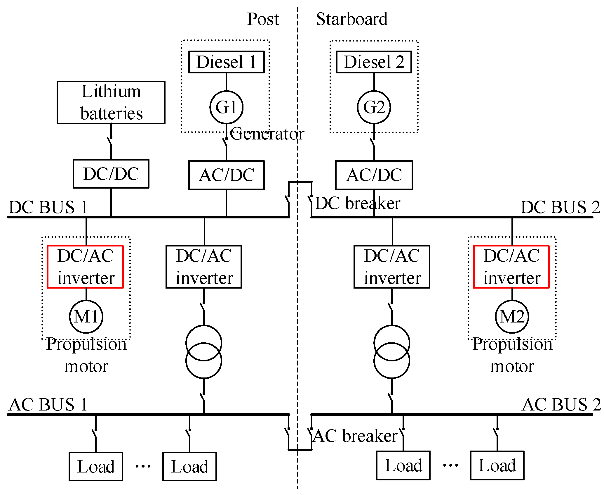
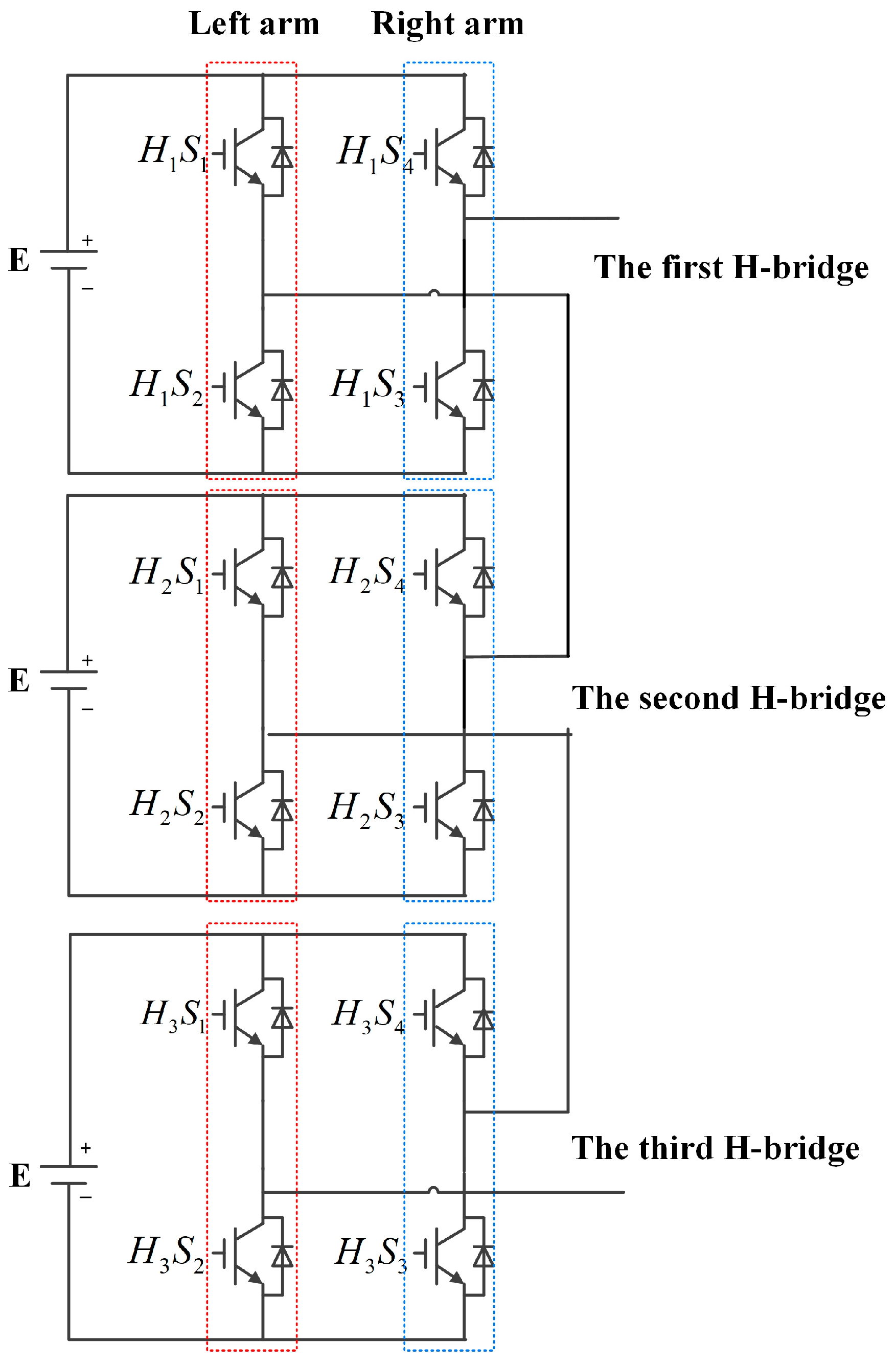
2.1. Operation State

The single phase of a cascaded seven-level inverter is shown in Figure 3.
As shown in Figure 4, carrier disposition modulation is used to output the Pulse Width Modulation (PWM) signal for the inverter. The bridge arm is driven to switch, in turn, in a determined period. Each H-bridge provides a different output voltage at different times. The total output voltage is the sum of the output voltages of each H-bridge. Therefore, the inverter composed of N H-bridges can generate 2N + 1 levels.
The switching pattern and output voltage waveforms are shown in Figure 4.
As shown in Figure 5, each H-bridge independently manages distinct segments of the sinusoidal reference. Consequently, even though the modulation technique of each H-bridge is fundamentally similar, their respective output voltage waveforms are not identical. When an open-circuit fault occurs in an IGBT, it will lead to failure to drive. The conduction state of the faulty H-bridge will be affected, which means one voltage level is skipped. The total output voltage also skips the parts that the H-bridge is responsible for. The voltage wave will be asymmetric and distorted due to the loss of voltage level. In addition, the phase voltage will become unbalanced in the three-phase system, such as the motor drive system.

2.2. Fault-Tolerant State

To maintain the normal operation of the inverter system, the faulty H-bridge must be removed from the system. In [38], the faulty H-bridge is directly isolated by an isolation switch in parallel. Once one IGBT faults, the whole H-bridge cell will be cut off, and other healthy H-bridge cells will be reconfigured to work in the five-level operation. The other method in [34] involves the PWM control forcing the corresponding IGBTs on or off. The faulty H-bridge is in a forward or reverse bypass state. In contrast, the response time is accelerated because there is no need to use isolation switches to short circuit the faulty H-bridge. However, the adjustment range of the motor’s torque and speed is reduced when the inverter uses those methods in the motor drive system because the state of the H-bridge is lost, which causes a reduction in output voltage capability of inverter. The load capacity is reduced due to the reduction in the fundamental amplitude. The increase in duty cycle can increase the amplitude. However, the power loss will increase with the increase in duty cycle, and the junction temperature will increase due to the increase in IGBT power loss. This will cause the IGBT failure rate to increase, thus reducing the reliability of the system.
For fault diagnosis in a ship’s DC electrical system, there has been a lot of research developments, such as a convolutional-neural-network-based method [21], Res-BiLSTM [22], and a layering linear discriminant analysis [23].
For fault-tolerant control in the ship’s system, a five-phase fifteen-slot four-pole interior PMSM without the neutral point was modified [24]. This method requires a redesign of the motor and is costly. A modified lookup table, flux, and torque hysteresis bands are designed to improve the functioning of the fault-tolerant DTC of five-phase induction motor (FPIM) drive [25]. This method may not be suitable for a PMSM in electric ships. The method in [26] solves this problem by adding two TRIACs to pass faulty devices. And two additional switches are added to the circuit. This can be interpreted as faulty healthy devices being replaced by redundant devices. This method adds additional devices.
For these unresolved doubts, a stratified reconfiguration carrier disposition SPWM fault-tolerant strategy is proposed. The faulty device is bypassed without an isolating switch. The fundamental voltage amplitude is improved as much as possible after fault tolerance. And the reliability of the system is also increased.

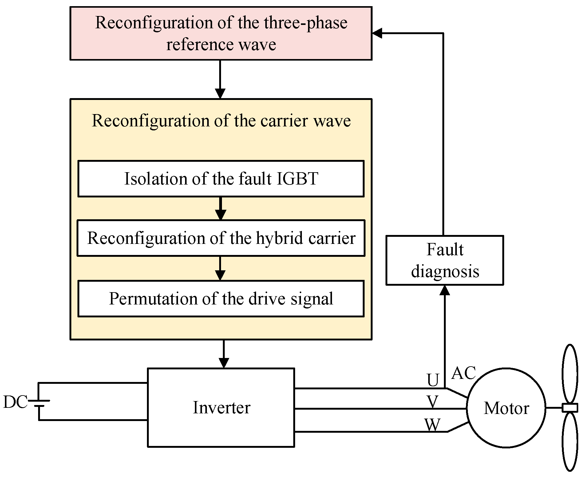
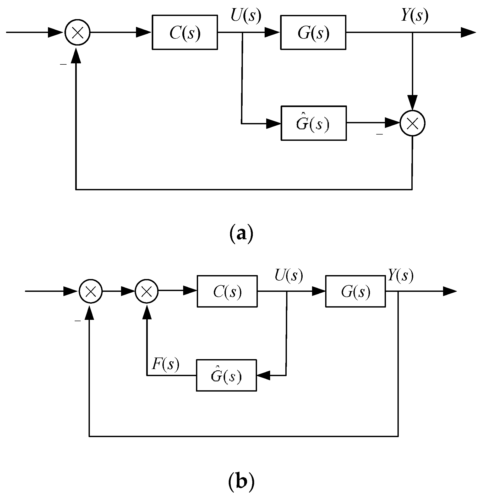
3. A Stratified Reconfiguration Carrier Disposition SPWM Fault-Tolerant Control Strategy

Figure 6 shows the schematic diagram of the stratified reconfiguration disposition SPWM fault-tolerant control strategy. There are no additional devices to achieve fault-tolerant control.
In Figure 6, the output voltage information of the inverter is used for real-time fault diagnosis. When the fault information is detected, the fault-tolerant control method based on reconstructed SPWM signal is activated. This fault-tolerant control method can be divided into modulating wave reconfiguration and carrier reconfiguration. The carrier reconfiguration includes the isolation of the fault IGBT, the reconfiguration of the faulty H-bridge carrier, the reconfiguration of the healthy H-bridge carrier, and the permutation of the drive signal. This method can alleviate the influence of the fault.

3.1. Reconfiguration of the Three-Phase Reference Wave

In the cascaded multilevel inverter, voltage references for phase A, B, and C can be expressed as follows:
{ u A r e f = a × m a sin ( 100 π t ) u B r e f = b × m a sin ( 100 π t + θ AB ) u C r e f = c × m a sin ( 100 π t θ AC )
where a, b, c are the amplitude of the reference voltage of phases A, B and C, respectively, and θAB, θAC, θBC are the phase angles between AB, AC, and BC, respectively. During the normal operation of the inverter, a = b = c = n, n is number of cascaded H-bridges, θAB = θAC = θBC = 120°.
The vector diagram of the three-phase reference voltage is presented in Figure 7a; it shows that the output voltage of the inverter is balanced. However, equivalent voltage cannot be output according to the reference wave due to fault, as shown in Figure 7b–d.
In Figure 7b, when the fault occurs in phase A, it will be a < b = c. The inverter will not be able to output a three-phase balanced voltage waveform that matches the reference modulation waveform, as shown in Figure 7a. In Figure 7c, when the fault occurs in phases A and B, it will be a = b < c. The inverter will not be able to output a three-phase balanced voltage waveform either. Therefore, the phase of the three-phase reference voltage must be reconfigured. The reconfiguration algorithm is as follows:
When the fault of the H-bridge occurs in a single phase, to reconfigure the phase of the H-bridge after isolating the faulty H-bridge, the algorithm is as follows:
{ a 2 + b 2 2 a b cos ( θ AB ) = a 2 + c 2 2 a c cos ( θ AC ) = b 2 + c 2 2 b c cos ( θ BC ) θ AB + θ AC + θ BC = 360 °
If the fault of the H-bridge occurs in two phases, to reconfigure the phase of the H-bridge after isolating the faulty H-bridge, the algorithm is as follows:
{ c = a 2 + b 2 + a b , a = b = n 2 θ AB + θ AC + θ BC = 360 ° θ AC = θ BC = cos 1 ( a b )
If the fault of the H-bridge occurs in three phases, to reconfigure the phase of the H-bridge after isolating the faulty H-bridge, the algorithm is as follows:
{ c = a = b = n 2 θ AB + θ AC + θ BC = 360 ° θ AB = θ AC = θ BC
When the three-phase voltage is unbalanced, the line voltages will also be unbalanced. The imbalance line voltage of the three-phase system may lead to an unstable operation of the power equipment, reduced power factor, energy loss, and other problems. Therefore, when a fault occurs, the three-phase voltage should be balanced first.

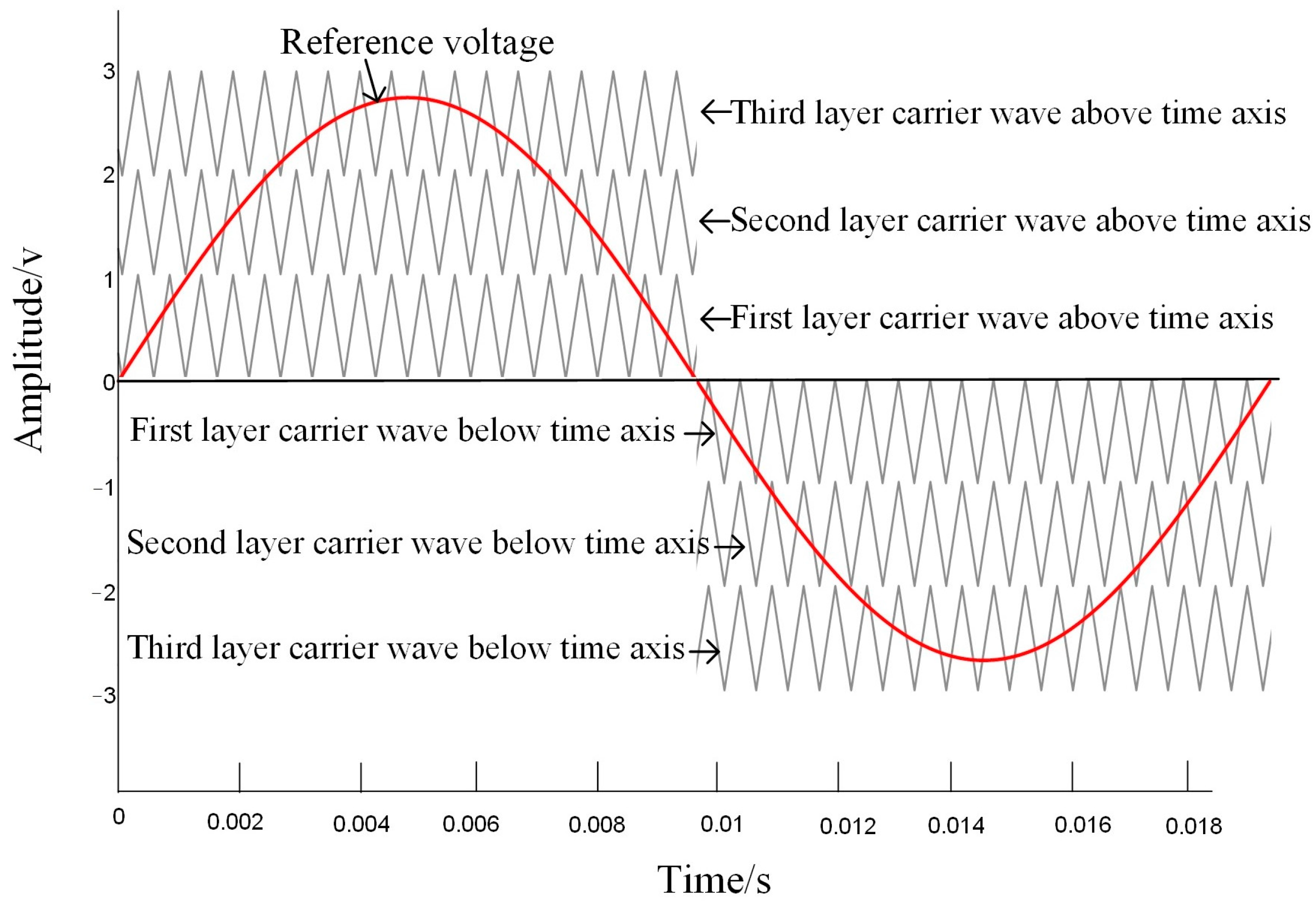
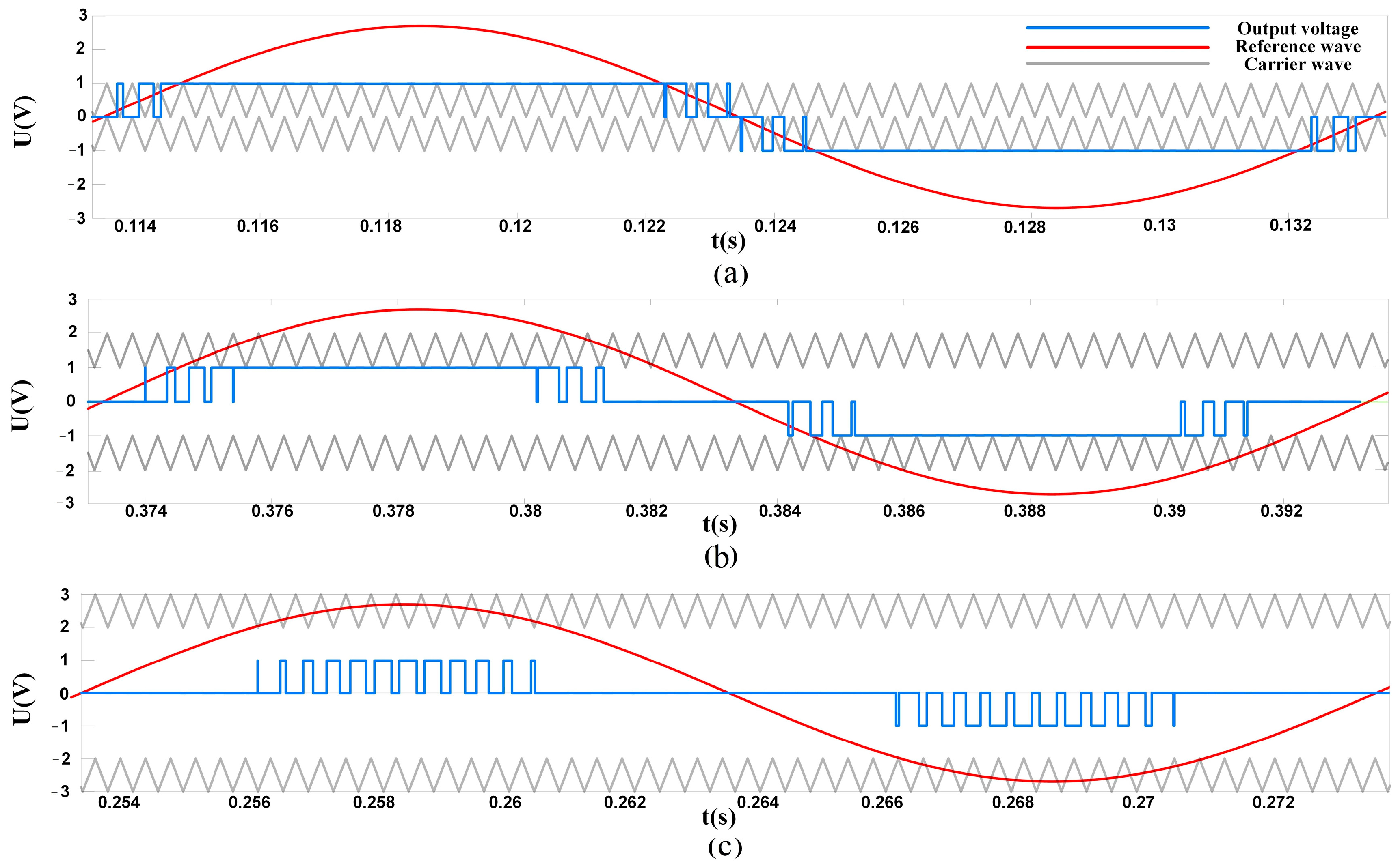
3.2. Reconfiguration of the Carrier Signal

After three-phase voltage balance reconfiguration, the equivalent output voltage of each phase is determined. To achieve the desired output, three steps are presented: (i) isolation of the fault IGBT; (ii) reconfiguration of the hybrid carrier; and (iii) redistribution of the drive signal.

3.2.1. Isolation of the Fault IGBT

When a signal IGBT fails, the fault diagnosis method is used to detect the fault location. If the fault occurs in the IGBT of the reverse conduction circuit, k = 1. If the fault occurs in the IGBT of the forward conduction circuit, k = 0. The carrier signal of the faulty H-bridge is modified to the following:
{ C + = n n j C + + ( 1 ) k ( n + 1 i ) C = n n j C ( 1 ) k ( n + 1 i )
where C+, C are the carrier signals above the time axis and below the time axis of the faulty H-bridge, respectively. C + , C are the corresponding carrier signal after fault-tolerant control. The two indexes j and i are the number and location of faulty H-bridges.
If a fault occurs in a cascaded H-bridge seven-level inverter, the reference and carrier signals will be reconfigured to make the drive signal of the faulty IGBT set to zero and the remaining topology can be regarded as a cascaded five-level inverter. If the second fault occurs in the same conduction loop in different H-bridge, the remaining topology can be seen as a cascaded three-level inverter.
If the second fault occurs in the different conduction loop in a different H-bridge, it means that there is a healthy positive bridge arm in one faulty H-bridge and a healthy reverse bridge arm in another faulty H-bridge. These remaining healthy bridge arms in the faulty H-bridges will be fully utilized. In other words, for one fault, the faulty H-bridge with a healthy positive conduction loop can output two voltage levels of +E and 0. For another fault, another faulty H-bridge with a healthy negative conduction loop can output two voltage levels of −E and 0. Then, when the two faulty H-bridges are combined as far as possible, the output voltage wave can be reduced by only two voltage levels, that is, the seven levels will be five levels. Especially when more H-bridges are cascaded, the on-state of the H-bridges is utilized as much as possible to increase the amplitude of the output voltage after fault tolerance.

3.2.2. Reconfiguration of the Hybrid Carrier

The reconfiguration of the remaining carriers can be carried out using traditional level-shifted pulse width modulation. However, the degradation of the voltage will cause a reduction in the fundamental amplitude. Therefore, the hybrid carrier will be used to improve the duty cycle.
In order to increase the duty cycle, the top-most and bottom-most carriers are replaced by a triangular–trapezoidal signal, and the triangular–trapezoidal signal has the same frequency as the replaced triangular signal. The H-bridge is a conduction state when the modulated signal is bigger than that of the trapezoidal carrier signal. Therefore, the conduction time is longer because carriers are triangular–trapezoidal signals. That is, the H-bridge is a conduction state for a longer time in one cycle. The duty cycle can be increased by this hybrid carrier.

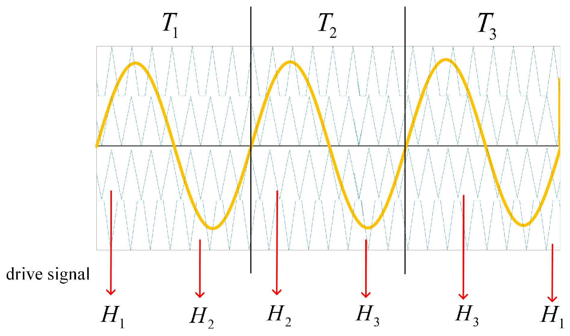
3.2.3. Redistribution of Drive Signal

A larger duty cycle can provide a higher average power of the inverter output but it also increases the loss and temperature of the IGBT. The loss may cause a reduction in IGBT reliability. Therefore, in order to decrease the duty cycle of the healthy bridge, the healthy devices in faulty bridges are used to contribute to the output voltage through the redistribution of the drive signal.
When a single IGBT fault occurs in the H-bridge, the forward or reverse conduction will be blocked. However, the fault cell is in the bypass state after the isolation of the fault IGBT, and the remaining conduction state is not used. To reduce the power loss, the remaining conduction state in the faulty cell will be used to contribute to the output.
As shown in Figure 8, the drive signal is alternated at different periods. It can make the remaining conduction state of the faulty H-bridge output the highest and lowest levels. The power loss will be evenly distributed. Meanwhile, the switching times of the switch tube are equal in a half period, which also balances the power among the output modules.

4. Simulation Results and Analysis

4.1. Simulation Results

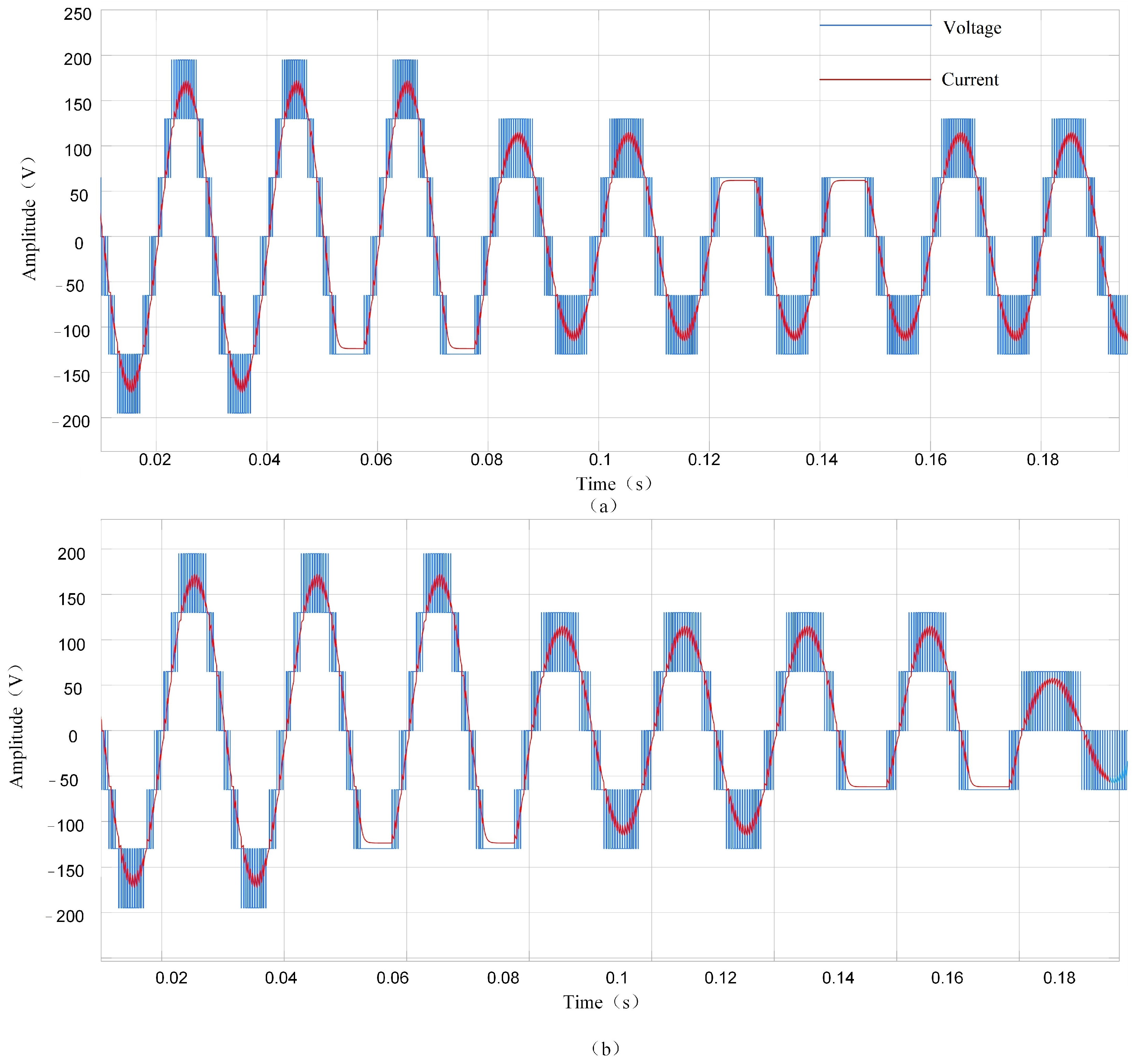
4.1.1. Seven-Level Inverter

To verify the efficiency of the proposed method, this section will show its simulation results. Because this paper only focuses on fault-tolerant control, the simulation model is built based on the assumption that the fault has been detected and diagnosed correctly.
A cascaded H-bridge seven-level inverter system is built using MATLAB/Simulink R2022b software. Every input DC voltage value is set to 65 V. A series-connected R-L impedance of 21 (Ω) and 8 (mH) is taken into consideration, which is connected to the terminals of the inverter as a load. As shown in Figure 9, an open fault is generated in H3S2 in the first H-bridges at t = 0.02 s. The voltage in that phase loses a level and becomes asymmetrical.
At t = 0.8 s, the reference and carrier signals are reconfigured. The symmetry of the phase voltage is restored. However, the phase voltage is degraded from seven levels to five levels. And the switching times are increased due to the reconfiguration of the modulation signal. Therefore, the drive signal is redistributed. As shown in Figure 10a, the faulty H-bridge is used to output voltage. The number of switches in a period is reduced, which causes the reduction in the power loss of the healthy H-bridge, as shown in Figure 10b,c.
At t = 0.12 s, the second fault occurs in H2S1 (Figure 9a) and H2S4 (Figure 9b), respectively. As shown in Figure 9a, because H2S1 is on the forward conduction loop, the output voltage keeps the five-level in post-fault operation. As shown in Figure 9b, the output is reduced to three levels due to the fact that H2S4 is in the reverse conduction state. In conclusion, the performance of the output voltage has improved as much as possible.

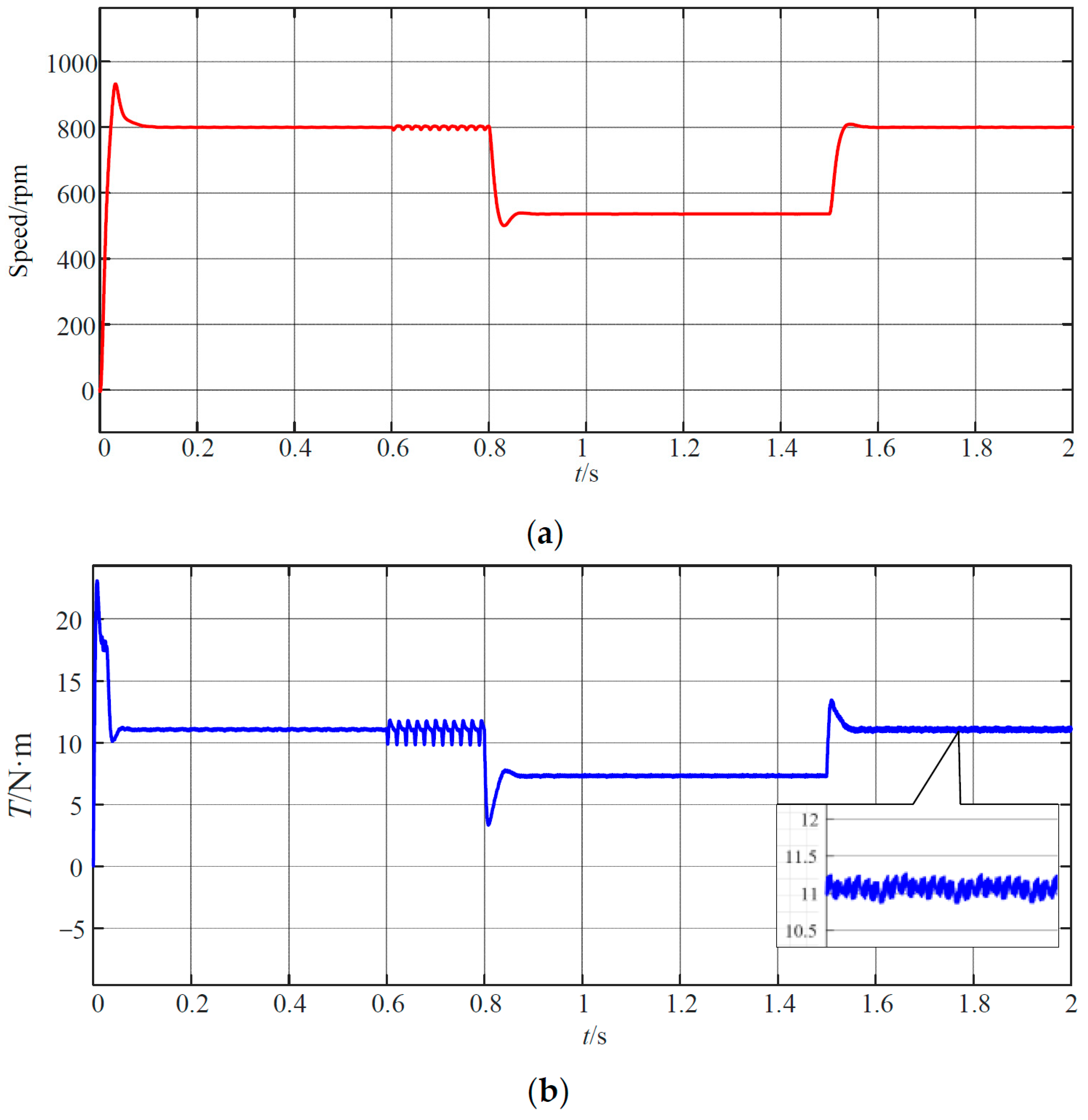
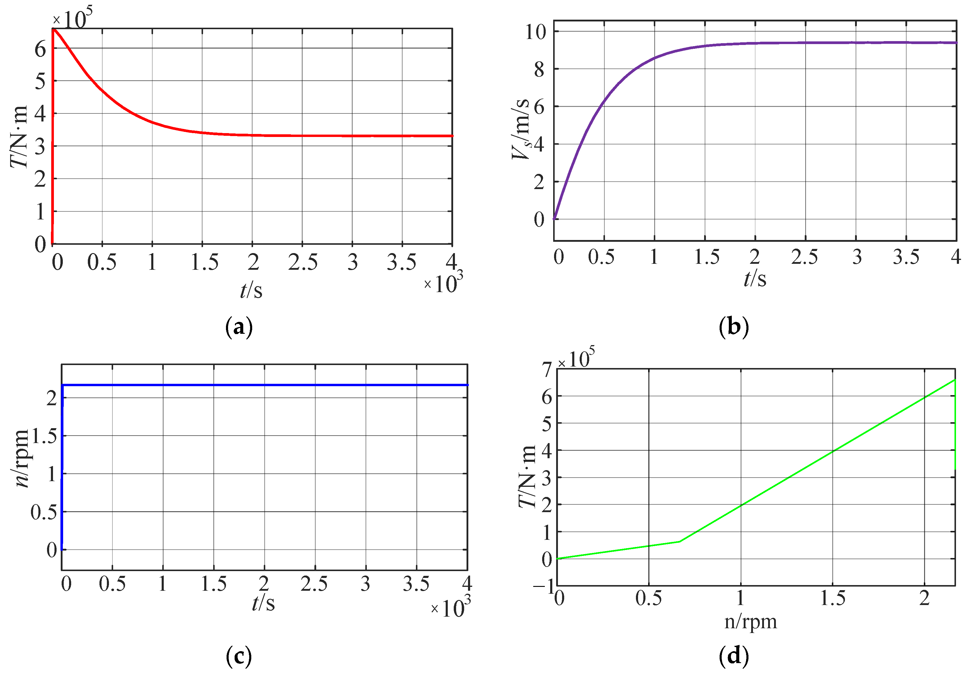
4.1.2. Motor Drive System

To verify the effectiveness of the proposed strategy, a simulation model of the PMSM drive system is built, and the proposed method is also applied. The parameters of IGBT/Diode are shown in Table 1. The DC voltage is 35 V. The PMSM parameters are shown in Table 2.
(a)
The parameters of Proportional Integral (PI) controller in the rotational speed loop
In order to facilitate the parameter setting of the speed loop PI controller, the motor motion equation of PMSM is written as follows:
J d ω m d t = T e T L B ω m
T e = 3 2 p n i q [ i d ( L d L q ) + φ f ]
where ωm is the mechanical angular speed of the motor; J is the moment of inertia; B is the damping coefficient; and TL is the load torque. Active power damping is used to adjust the parameters of the speed loop PI controller, and the active power damping is defined as follows:
i q = i q ' B a ω m
When the control strategy (id = 0) is adopted and the motor is assumed to start under no-load (TL = 0), the following expression can be derived:
d ω m d t = 1.5 p n φ f J ( i q ' B a ω m ) B J ω m
By assigning the poles of (10) to the desired closed-loop bandwidth β, the transfer function of the speed relative to the Q-axis current can be obtained as follows:
ω m ( s ) = 1.5 p n φ f / J s + β i q ' ( s )
The coefficient of active power damping can be obtained by (10) and (11):
B a = β J 1.5 p n φ f
Then, the expression of the speed loop controller is as follows:
i q * = ( k p w + k i w s ) ( ω m * ω m ) B a ω m
Therefore, the proportional gain and integral gain of the PI controller can be adjusted by the following formula:
{ K p w = β J 1.5 p n φ f K i w = β K p w
where β is the expected frequency band bandwidth of the speed loop. The bandwidth of the speed ring is selected as 50 rad/s. The parameters of the speed loop PI controller are calculated by (14) and the parameters of the motor.
(b)
The parameters of PI controller in the current loop
The conventional PI controller is combined with the feedforward decoupling control strategy. The voltage of the d–q-axes can be obtained as follows:
{ u d = ( k p d + k i d s ) ( i d * i d ) ω e L q i q u q = ( k p q + k i q s ) ( i q * i q ) + ω e ( φ f + L d i d )
where Kpd and Kpq are the proportional gains of the PI controller, and Kid and Kiq are the integral gains of the PI controller. Internal model control has the advantages of a simple structure and a single parameter. Therefore, the internal model control strategy is used to design and adjust the parameters of the PI controller.
Figure 11a shows a typical internal model control block diagram, where G ^ ( s ) is the internal model; G(s) is the controlled object; and C(s) is the internal model controller. According to the classic automatic control principle, the block diagram shown in Figure 11b can be obtained through an appropriate equivalent transformation shown in Figure 11a, and its equivalent controller is as follows:
F ( s ) = [ I C ( s ) G ^ ( s ) ] 1 C ( s )
where I is the identity matrix. If the internal model modeling is accurate, G ^ ( s ) = G(s). Then, there is no feedback in the system, and the transfer function of the system is as follows:
G c ( s ) = G ( s ) C ( s )
To ensure the stability of the system, G(s) and C(s) need to be stable. The current loop of a control system can be approximated as a first-order system. C(s) is defined by G ^ ( s ) = G(s):
C ( s ) = G ^ 1 ( s ) L ( s ) = G 1 ( s ) L ( s )
where L(s) = αI/(s + α), and α is the design parameter. By substituting (18) into (16), the designed internal model controller can be obtained, which is as follows:
F ( s ) = α [ L d + R s 0 0 L q + R s ]
By substituting (19) into (16), Gc(s) can be calculated as follows:
G c ( s ) = α α + s I
By comparing (20) and (15), it can be seen that the adjustment parameters of the PI controller meet the following:
{ K p d = α L d K i d = α R K p q = α L q K i q = α R
According to the parameters of the motor, α = 1000 rad/s. According to (21), the parameters of the PI controller in the current loop can be calculated. The calculated parameters of the PI controller may not be optimal. In the process of simulation, it is necessary to further debug the parameters to achieve the best control effect. The controller parameters obtained through debugging are shown in Table 3.
The PI controller parameters in Table 2 determined based on a stability analysis are entered into the MATLAB model. When the load torque TL is replaced by the fan load torque, the speed is as shown in Figure 12. The load characteristics of the fan are as follows:
T L = T f + k n 2
where Tf is friction torque on the bearing; and k is proportional coefficient.
As shown in Figure 12, the initial speed of the propulsion motor PMSM is 800 rpm. The load torque of the propeller is suddenly loaded to the PMSM at t = 0.2 s. The motor speed oscillates accordingly and then becomes stable. IGBT faults happen in the first and third H-bridges at t = 0.6 s. The effect of the speed will become worse, and the speed will fluctuate between 790.9 rpm and 804.5 rpm and show the characteristics of periodic changes. After a delay for fault detection and diagnosis, the proposed method is put into use at t = 0.8 s. It will be noted that the neutral point cannot be offset because the motor drive system requires phase voltage balance. Therefore, the three-phase reference signals are reconfigured by (4). Isolating the faulty IGBT stabilizes the speed of the motor. However, it decreases from 800 rpm to 530 rpm due to the reduction in voltage level. At t = 1.5 s, the SPWM strategy of the hybrid carrier is used. The motor speed increases to 590 rpm. Therefore, the proposed fault-tolerant control is realized to achieve a three-phase voltage balance and constant frequency in the seven-level or a five-level voltage of the motor drive system. In addition, the IGBT power loss of the H-bridge is reduced.
To solve the voltage drop problem, there are two ways to restore speed. One is to increase the voltage value of the DC bus. However, the ship’s DC bus cannot be added arbitrarily. Another one is to reduce the excitation current of the motor and thereby reduce the excitation flux. The motor speed will be increased under the condition of ensuring the voltage balance. The excitation flux of PMSM is provided by a permanent magnet, and this flux is constant. If the magnetic flux strength is expected to be reduced, the air gap magnetic flux can only be weakened by increasing the demagnetization component of the stator current. In this way, flux-weakening control can be achieved, just like for the separately excited DC motor. Under these circumstances, the d-axis current id must be maintained at a negative value to shift the operating point laterally into the operable region. The negative d-axis current is the so-called flux-weakening current, and flux-weakening control is responsible for driving the flux-weakening current such that the motor always operates inside the operable region even when the operating conditions vary [39].
Flux-weakening control is performed at 1.5 s. The speed and torque waveforms are shown in Figure 13.
As shown in Figure 13, speed and torque can be restored. Therefore, the possibility of uninterrupted operation of the motor drive system is improved as much as possible.

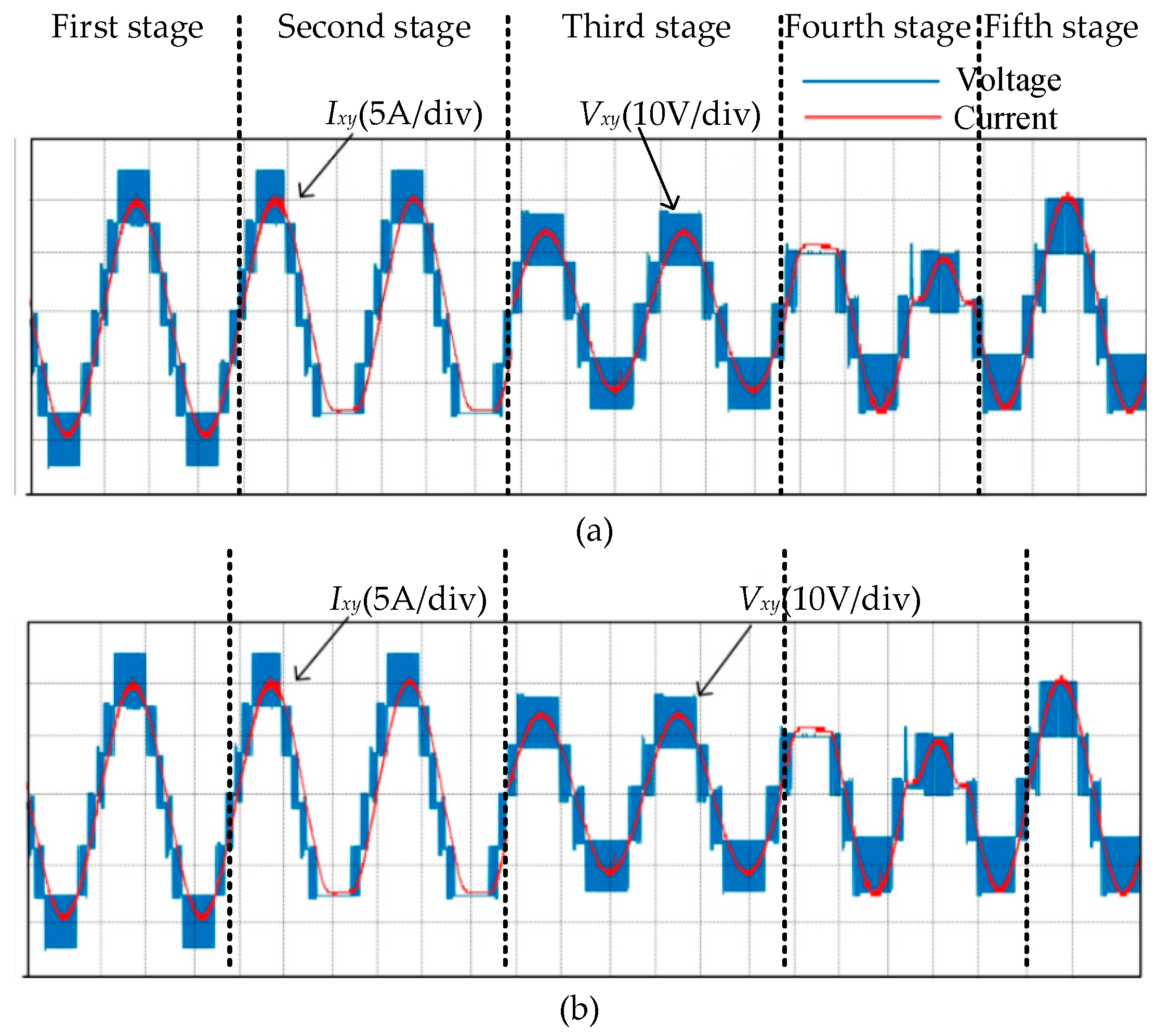
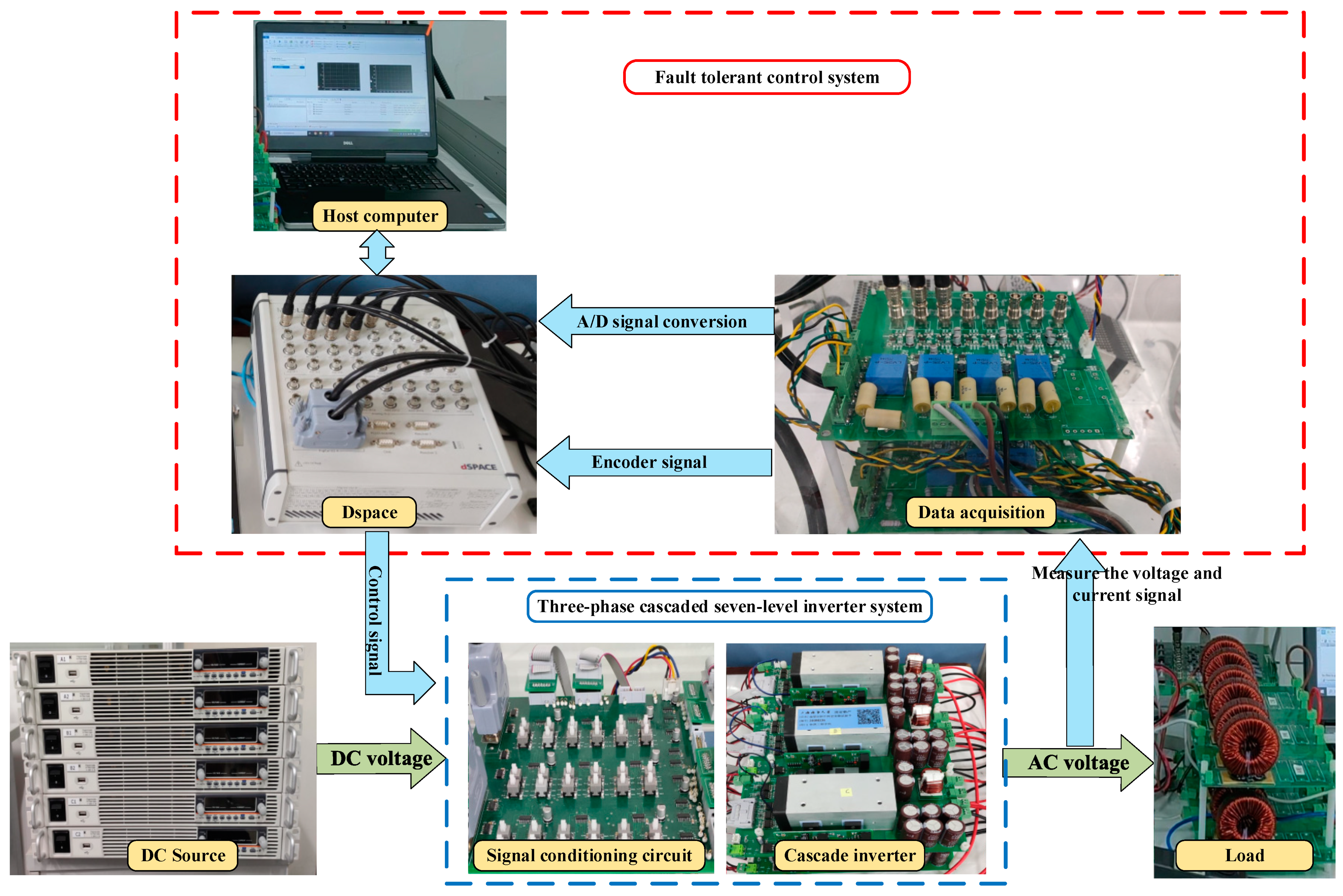
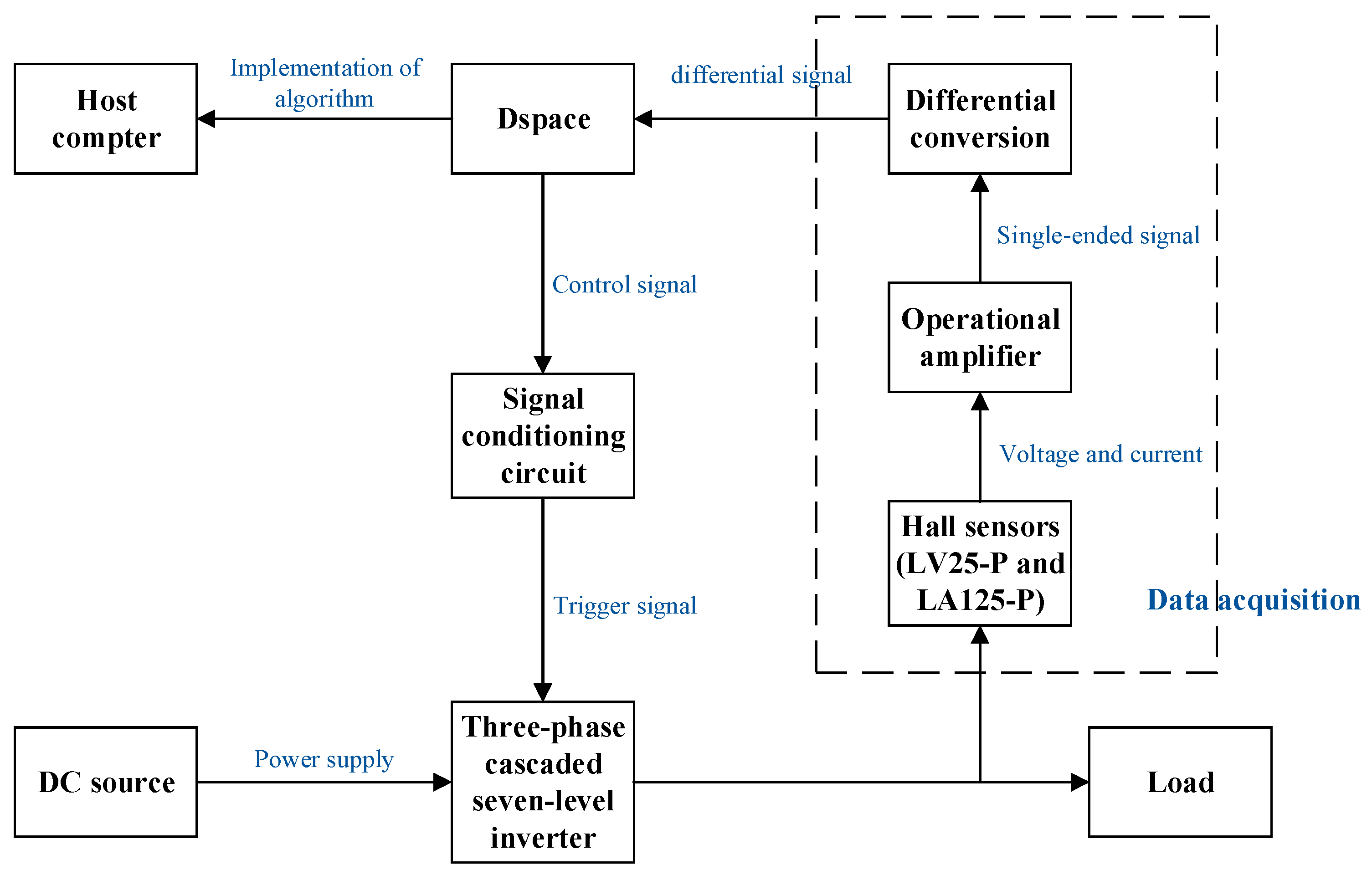
4.2. Experimental Results

Figure 14 depicts the experimental platform. It consists of a cascaded H-bridge seven-level inverter as a power stage, and the control strategy is implemented in the MicroLabBox dSPACE system that generates the signals of the switch gates. Due to the limitations of the experimental conditions, the DC source is used to simulate the ship’s DC bus, and PMSM is replaced by RL. Table 4 shows the main parameters of the system. We have selected the IGBT IKW50N65F5 as the power switch transistor, which includes a built-in reverse diode.
As shown in Figure 15, the three-phase cascaded seven-level inverter is supplied by power sources. And the control signal given by the controller dSPACE needs to go through the signal conditioning circuit to the three-phase cascaded five-level inverter. Meanwhile, the signal conditioning circuit has the function of setting faults. The output voltage signal of the three-phase cascaded seven-level inverter is directly sent to the load. The voltage and the current sensor are used to monitor the output signal of the inverter in real time. The collected voltage and current signals are sent to the controller dSPACE as feedback signals. The collected phase voltage signal is used as the monitoring signal of fault diagnosis, and it is used to realize fault-tolerant control.
Figure 16 shows the changes in the output voltage and output current under fault-tolerant control of the proposed strategy. This process can be divided into five states: normal operation, IGBT failure, fault-tolerant control, second IGBT failure, and second fault-tolerant control.
As shown in Figure 16a:
(1)
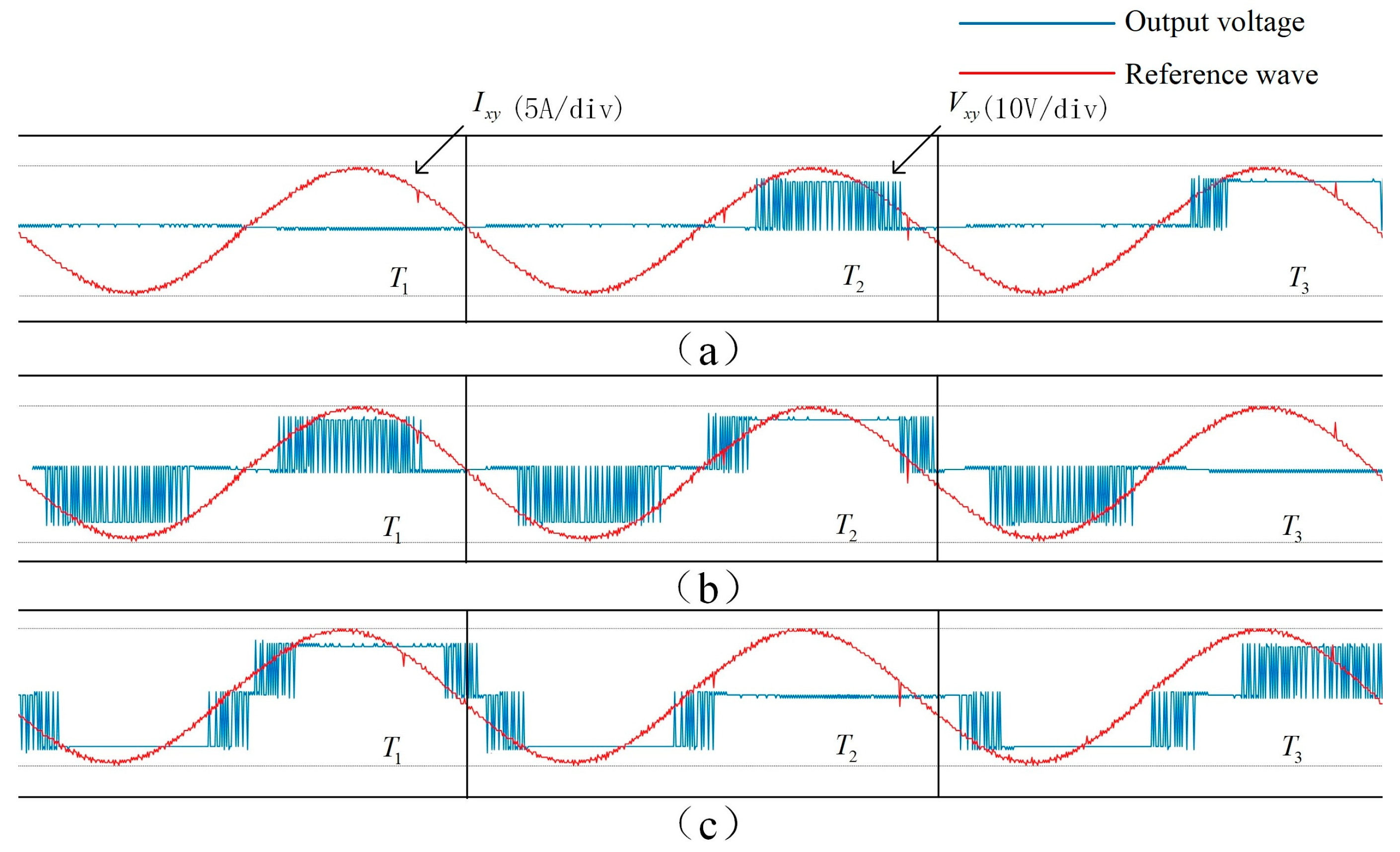
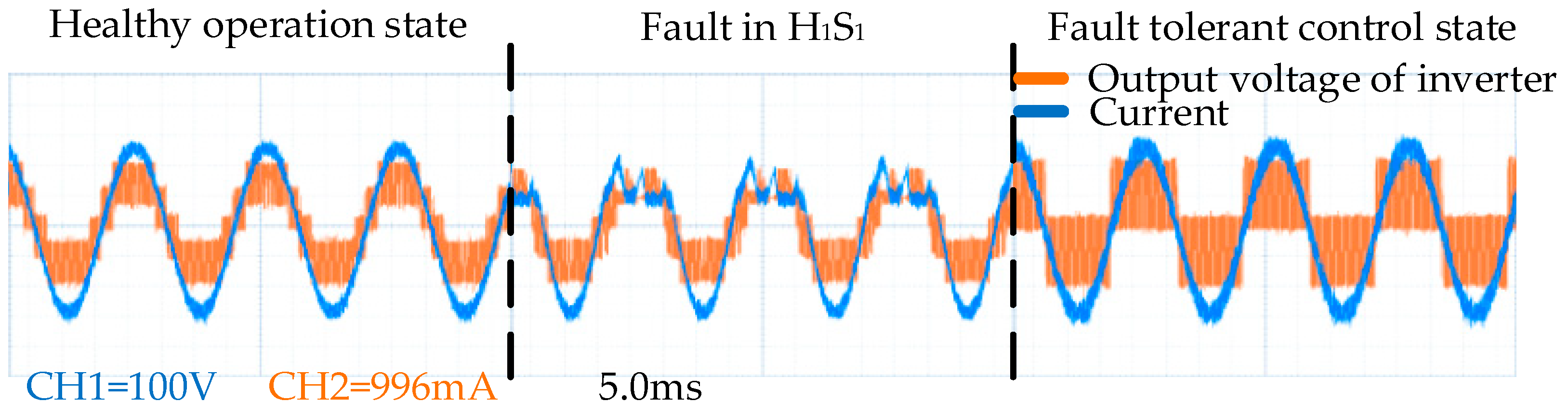
In the first stage, the inverter is in a normal working state. The output voltage of the inverter is a symmetrical seven-level voltage waveform, with the output current being a sine wave.
(2)
In the second stage, due to the IGBT (H3S4) on the H3 reverse conduction circuit having an open-circuit fault, there is a level reduction in the output voltage on the negative half axis. As a result, the total harmonic distortion of the output voltage increases and the output current is distorted.
(3)
In the third stage, a fault-tolerant control method is adopted based on the reconstructed SPWM signal. Although the amplitude of the output voltage is reduced and the voltage level is reduced compared to the normal state, the inverter can output a symmetrical five-level voltage waveform. This means the total harmonic distortion of the output voltage is reduced during faults, and the output current is restored to a sinusoidal waveform.
(4)
In the fourth stage, the IGBT (H2S4) on the H2 reverse conduction circuit has an open-circuit fault. As a consequence, the output voltage of the five levels loses one voltage level on the negative half axis, and the total harmonic distortion increases further.
(5)
In the fifth stage, the inverter can output a symmetrical three-level voltage by the proposed fault-tolerant control strategy, and the output current is restored to a sine wave.
It can be seen that both single IGBT faults and double IGBT faults can be achieved using the proposed method for fault-tolerant control.
As shown in Figure 16b, identical to the first three stages of the above analysis, the proposed fault-tolerant control method was used to achieve merely one-level reduction. Nevertheless, the fourth stage is unlike the above situation. The IGBT (H2S1) on the H2 forward conduction circuit leads to an open-circuit fault, causing a level reduction in the first half cycle of the output voltage. In the fifth stage, by using the proposed fault-tolerant control method again, it can be found that fault-tolerant control can be achieved without reducing the level, and the total harmonic distortion of the output voltage can be improved.
As a consequence, the proposed fault-tolerant control method not only effectively achieves fault-tolerant control, but also improves the performance of the output voltage in terms of the fault types that cause different conduction circuit blockages for different H-bridges.
As shown in Figure 17, the faulty H-bridge is used to output the forward voltage in T1. Meanwhile, the second and third H-bridges are in the conduction state, which can reduce power loss. In addition, for the whole period, the number of switches on each H-bridge is the same as in the half period. This can balance the power loss of each H-bridge as much as possible.
In the experimental results, the performance of the output voltage is improved as much as possible in post-fault operation, and the power loss of the healthy H-bridge is reduced, which can improve the reliability of the ship’s power system.

4.3. Comparison with Other Methods

The fault-tolerant control effect of [31] in the three-phase grid-connected experimental platform is shown in Figure 18. The whole process is divided into three states: healthy operation state, H-bridge fault state, and fault-tolerant control state.
During H-bridges’ healthy operation, the inverter can output a symmetrical five-level voltage waveform. Nevertheless, when an open-circuit fault occurs in H1, the output level cannot be maintained at five. Then, the waveform of the inverter voltage is distorted, and the current of the grid also shows asymmetric distortion. After fault-tolerant control in [31], the inverter only outputs three-level voltage although the peak value of the output voltage is essentially unchanged, and the waveform of the output voltage is symmetrical. This fault-tolerant method reduces the output voltage by three levels after only one fault in the H-bridge. Although limited to the experimental conditions, the motor experiment not being able to be carried out. The results of the grid-connected experiment with RL show the current’s harmonic increase. This is a disaster for motor operation. Compared with [31], the proposed fault-tolerant control method can both be applied to higher level inverters and maintain the level number of output voltage as much as possible. Thus, the total harmonic distortion of the current may be reduced.
The fault-tolerant control effect in [40] is similar to that of the proposed method in this paper. However, when a single IGBT fault occurs in the third state, the healthy bridge arm of the faulty H-bridge is not utilized. The switching frequency of some IGBT devices in the third state is reduced by the proposed method based on reconfiguration SPWM, and thus the IGBT power loss is reduced.
The torque ripple is estimated to be 1.6 Nm in [25]. The torque ripple of the proposed method is around 0.42 Nm as shown in Figure 13b, which is about 73% lower than in the scheme proposed by Chikondra et al. [25].
More investigations that can adapt to the existing systems in ships are needed, including research on factors which have not been considered by the proposed method. The following are some examples:
(a)
The DC power supply is replaced by the actual ship’s DC bus;
(b)
Wind disturbance factors should be considered, such as mean wind pressure, variable wind pressure, the ship’s absolute heading angle, absolute wind angle, drift angle, etc.;
(c)
Wave interference factors should be considered, such as irregular wave drift force and moment, wave and ship encounter angle, drift force coefficient, wave force interference coefficient, etc.;
(d)
The electromagnetic interference generated by the inverters needs to be dealt with.

5. Conclusions

A stratified reconfiguration carrier disposition SPWM fault-tolerant control strategy for a ship’s PMSM drive system is proposed. Compared to the inverter topology with additional devices [26,27,28,29,31,34,35], the proposed method is only based on software. This makes it useful for ships where space is limited. Thus, the proposed hybrid carrier could improve the duty cycle of SPWM. The experimental results show that the decrease problem [37] of the fundamental amplitude of the output voltage is solved in faulty conditions. Because the conduction state of the healthy bridge arm in the faulty H-bridge is fully utilized, the performance of the output voltage is improved. Furthermore, the switching times of the IGBT are identical over a period. That is to say, the power losses of IGBTs are even. Therefore, the proposed method is suitable for motor drive applications that do not require maintaining voltage amplitude.

Author Contributions

Conceptualization, F.Z. and Z.Z. (Zhonglin Zhang); methodology, F.Z., Z.Z. (Zhiwei Zhang) and Z.Z. (Zhonglin Zhang); software, Z.Z. (Zhonglin Zhang); formal analysis, F.Z., Z.Z. (Zhiwei Zhang), Z.Z. (Zhonglin Zhang), J.H., T.W. and Y.A.; writing—original draft preparation, F.Z., Z.Z. (Zhiwei Zhang), Z.Z. (Zhonglin Zhang), J.H., T.W. and Y.A.; writing—review and editing, T.W. and Y.A. All authors have read and agreed to the published version of the manuscript.

Funding

This research received no external funding.

Institutional Review Board Statement

Not applicable.

Informed Consent Statement

Not applicable.

Data Availability Statement

Data are contained within this article.

Conflicts of Interest

Author Zhiwei Zhang was employed by Shanghai Power Industrial & Commerical Co., Ltd. The remaining authors declare that the research was conducted in the absence of any commercial or financial relationships that could be construed as a potential conflict of interest.

References

  1. Gao, D.; Wang, X.; Wang, T.; Wang, Y.; Xu, X. Optimal Thrust Allocation Strategy of Electric Propulsion Ship Based on Improved Non-Dominated Sorting Genetic Algorithm II. IEEE Access 2019, 7, 135247–135255. [Google Scholar] [CrossRef]
  2. He, Y.; Fan, A.; Wang, Z.; Liu, Y.; Mao, W. Two-phase energy efficiency optimisation for ships using parallel hybrid electric propulsion system. Ocean. Eng. 2019, 238, 1–30. [Google Scholar] [CrossRef]
  3. Gan, S.H.; Shi, W.F.; Xu, X.Y. Proposed Z-Source Electrical Propulsion System of a Fuel Cell/Supercapacitor-Powered Ship. J. Mar. Sci. Eng. 2023, 11, 1543. [Google Scholar] [CrossRef]
  4. Apsley, J.M.; Gonzalez-Villasenor, A.; Barnes, M.; Smith, A.C.; Williamson, S.; Schuddebeurs, J.D.; Norman, P.J.; Booth, C.D.; Burt, G.M.; McDonald, J.R. Propulsion Drive Models for Full Electric Marine Propulsion Systems. IEEE Trans. Ind. Appl. 2009, 45, 676–684. [Google Scholar] [CrossRef]
  5. Kim, M.-G.; Choi, J.-L.; Song, T.-H.; Kim, Y.-S.; Lee, S.-G. A control power module for a hybrid inverter systems to drive electric propulsion ships. J. Adv. Mar. Eng. Technol. 2018, 42, 75–81. [Google Scholar] [CrossRef]
  6. Kanellos, F.D.; Tsekouras, G.J.; Prousalidis, J. Onboard DC grid employing smart grid technology: Challenges, state of the art and future prospects. IET Electr. Syst. Transp. 2015, 5, 1–11. [Google Scholar] [CrossRef]
  7. Che, Y.B.; Xue, S.Y.; Wang, D.M. An AC Voltage Sensor-less Control Strategy for Ocean Ship Photovoltaic Grid-connected Inverter with LCL Filter. J. Coast. Res. 2018, 83, 109–115. [Google Scholar] [CrossRef]
  8. Yao, N.; Zhang, Z.; Zhang, Z.Y. Application of Photovoltaic Off-Grid Inverter in Marine Engineering. J. Coast. Res. 2020, 110, 193–196. [Google Scholar] [CrossRef]
  9. Rodr´ıguez, J.; Bernet, S.; Wu, B.; Pontt, J.O.; Kouro, S. Multilevel voltage-source-converter topologies for industrial medium-voltage drives. IEEE Trans. Ind. Electron. 2007, 54, 2930–2944. [Google Scholar] [CrossRef]
  10. Rodríguez, J.; Bernet, S.; Steimer, P.K.; Lizama, I.E. A survey on neutral-point-clamped inverters. IEEE Trans. Ind. Electron. 2010, 57, 2219–2230. [Google Scholar] [CrossRef]
  11. Mathew, J.; Rajeevan, P.P.; Mathew, K.; Azeez, N.A.; Gopakumar, K. A multilevel inverter scheme with dodecagonal voltage space vectors based on flying capacitor topology for induction motor drives. IEEE Trans. Power Electron. 2013, 28, 516–525. [Google Scholar] [CrossRef]
  12. Peng, H.; Hagiwara, M.; Akagi, H. Modeling and analysis of swithing-ripple voltage on the DC link between a diode rectifier and a modular multilevel cascaded inverter. IEEE Trans. Power Electron. 2013, 28, 75–84. [Google Scholar] [CrossRef]
  13. Menaka, S.; Muralidharan, S. Novel Symmetric and Asymmetric Multilevel Inverter Topologies with Minimum Number of Switches for High Voltage of Electric Ship Propulsion System. Indian. J. Geo-Mar. Sci. 2017, 46, 1920–1930. [Google Scholar]
  14. Kumar, A.; Bhatia, R.S.; Nijhawan, P. Performance investigation of an innovative H-bridge derived multilevel inverter topology for marine applications. Indian J. Geo-Mar. Sci. 2020, 49, 441–449. [Google Scholar]
  15. Jeon, H.-M.; Hur, J.-J.; Yoon, K.-K. Control Method for Performance Improvement of BLDC Motor used for Propulsion of Electric Propulsion Ship. J. Korean Soc. Mar. Environ. Saf. 2019, 25, 802–808. [Google Scholar] [CrossRef]
  16. Muralidharan, S.; Gnanavadivel, J.; Muhaidheen, M.Y.S.; Menaka, S. Harmonic Elimination in Multilevel Inverter Using TLBO Algorithm for Marine Propulsion System. Mar. Technol. Soc. J. 2021, 55, 117–126. [Google Scholar] [CrossRef]
  17. Townsend, C.D.; Summers, T.J.; Watson, A.J.; Betz, R.E.; Clare, J.C. A Simplified Space Vector Pulse Width Modulation Implementation in Modular Multilevel Converters for Electric Ship Propulsion Systems. IEEE Trans. Transp. Electr. 2019, 5, 335–342. [Google Scholar]
  18. Chen, Y.; Li, Z.Y.; Zhao, S.S.; Wei, X.G.; Kang, Y. Design and Implementation of a Modular Multilevel Converter with Hierarchical Redundancy Ability for Electric Ship MVDC System. IEEE J. Emerg. Sel. Top. Power Electron. 2017, 5, 189–202. [Google Scholar] [CrossRef]
  19. Wang, B.; Cai, J.; Du, X.; Zhou, L. Review of power semiconductor device reliability for power converters. CPSS. Trans. Power. Electron. Appl. 2017, 2, 101–117. [Google Scholar] [CrossRef]
  20. Yaghoubi, M.; Moghani, J.S.; Noroozi, N.; Zolghadri, M.R. IGBT open-circuit fault diagnosis in a quasi-Z-source inverter. IEEE Trans. Ind. Electron. 2019, 66, 2847–2856. [Google Scholar] [CrossRef]
  21. Yan, G.; Hu, Y.; Shi, Q. A Convolutional Neural Network-Based Method of Inverter Fault Diagnosis in a Ship’s DC Electrical System. Pol. Marit. Res. 2022, 29, 105–114. [Google Scholar] [CrossRef]
  22. Xie, J.; Shi, W.; Shi, Y. Research on Fault Diagnosis of Six-Phase Propulsion Motor Drive Inverter for Marine Electric Propulsion System Based on Res-BiLSTM. Machines 2022, 10, 736. [Google Scholar] [CrossRef]
  23. Jin, G.; Wang, T.; Amirat, Y.; Zhou, Z.; Xie, T. A Layering Linear Discriminant Analysis-Based Fault Diagnosis Method for Grid-Connected Inverter. J. Mar. Sci. Eng. 2022, 10, 939. [Google Scholar] [CrossRef]
  24. Park, J. Multi-Phase Fault Tolerant PMSM Drive System; Texas A&M University: College Station, TX, USA, 2015. [Google Scholar]
  25. Chikondra, B.; Muduli, U.; Behera, R. An Improved Open-Phase Fault-Tolerant DTC Technique for Five-Phase Induction Motor Drive Based on Virtual Vectors Assessment. IEEE Trans. Ind. Electron. 2021, 68, 4598–4609. [Google Scholar] [CrossRef]
  26. Zhang, Z.; Wang, T.; Chen, G.; Amirat, Y. A Serial Fault-Tolerant Topology Based on Sustainable Reconfiguration for Grid-Connected Inverter. J. Mar. Sci. Eng. 2023, 11, 751. [Google Scholar] [CrossRef]
  27. Xia, Y.; Xu, Y.; Gou, B. A Data-Driven Method for IGBT Open-Circuit Fault Diagnosis Based on Hybrid Ensemble Learning and Sliding-Window Classification. IEEE Trans. Industr. Inform. 2019, 16, 5223–5233. [Google Scholar] [CrossRef]
  28. Song, W.; Huang, A.Q. Fault-tolerant design and control strategy for cascaded H-bridge multilevel converter-based STATCOM. IEEE Trans. Ind. Electron. 2010, 57, 2700–2708. [Google Scholar] [CrossRef]
  29. Yazdani, A.; Sepahvand, H.; MCrow, L.; Ferdowsi, M. Fault detection and mitigation in multilevel converter STATCOMs. IEEE Trans. Ind. Electron. 2011, 58, 1307–1315. [Google Scholar] [CrossRef]
  30. Aleenejad, M.; Iman-Eini, H.; Farhangi, S. Modified space vector modulation for fault-tolerant operation of multilevel cascaded H-bridge inverters. IET Power Electron. 2013, 6, 742–751. [Google Scholar] [CrossRef]
  31. Zhao, Z.; Wang, T.; Benbouzid, M. A fault-tolerant reconfiguration system based on pilot switch for grid-connected inverters. Microelectron. Reliab. 2022, 131, 114511. [Google Scholar] [CrossRef]
  32. Haji-Esmaeili, M.; Naseri, M.; Khoun-Jahan, H.; Abapour, M. Fault-tolerant structure for cascaded H-bridge multilevel inverter 538 and reliability evaluation. IET Power Electron. 2017, 10, 59–70. [Google Scholar] [CrossRef]
  33. Jahan, H.K.; Panahandeh, F.; Abapour, M.; Tohidi, S. Reconfigurable Multilevel Inverter with Fault-Tolerant Ability. IEEE Trans. Power Electron. 2018, 33, 7880–7893. [Google Scholar] [CrossRef]
  34. Mhiesan, H.; McCann, R.; Farnell, C.; Mantooth, A. Novel Circuit and Method for Fault Reconfiguration in Cascaded H-Bridge Multilevel Inverters. In Proceedings of the 2019 IEEE Applied Power Electronics Conference and Exposition (APEC), Anaheim, CA, USA, 17–22 March 2019; pp. 1800–1804. [Google Scholar]
  35. Maddugari, S.K.; Borghate, V.B.; Sabyasachi, S.; Karasani, R.R. A Linear-Generator-Based Wave Power Plant Model Using Reliable Multilevel Inverter. IEEE Trans. Ind. Appl. 2019, 55, 2964–2972. [Google Scholar] [CrossRef]
  36. Jalhotra, M.; Sahu, L.K.; Gautam, S.P.; Gupta, S. Reliability and energy sharing analysis of a fault-tolerant multilevel inverter topology. IET Power Electron. 2019, 12, 759–768. [Google Scholar] [CrossRef]
  37. Geng, C.; Wang, T.; Tang, T.; Benbouzid, M.; Qin, H. Fault-tolerant control strategy of the cascaded five-level inverter based on divided voltage modulation algorithm. In Proceedings of the 2016 IEEE IPEMC ECCE Asia, Hefei, China, 22–26 May 2016. [Google Scholar]
  38. Zhang, J.H.; Liu, Z.; Wang, T.; Benbouzid, M.E.H.; Wang, Y. An Arm Isolation and Reconfiguration Fault Tolerant Control Method Based on Data-driven Methodology for Cascaded Seven-level Inverter. In Proceedings of the 2018 IEEE 7th Data Driven Control and Learning Systems Conference (DDCLS), Enshi, China, 25–27 May 2018; pp. 939–943. [Google Scholar]
  39. Chen, J.J.; Chin, K.P. Minimum copper loss flux-weakening control of surface mounted permanent magnet synchronous motors. IEEE Trans. Power Electron. 2003, 18, 929–936. [Google Scholar] [CrossRef]
  40. Wang, T.Z.; Zhang, J.H.; Wang, H.; Wang, Y. A Multi-Mode Fault-Tolerant Control Strategy for Cascaded H-Bridge Multilevel Inverters. IET Power Electron. 2020, 13, 3119–3126. [Google Scholar] [CrossRef]
Figure 1. Ship DC electric propulsion system topology.
Jmse 12 00500 g001
Figure 2. The simulation results of direct startup: (a) torque waveform over time; (b) relative speed over time; (c) propeller speed over time; (d) torque waveform with speed change.
Jmse 12 00500 g002
Figure 3. Cascaded H-bridge seven-level inverter.
Jmse 12 00500 g003
Figure 4. Carrier disposition modulation.
Jmse 12 00500 g004
Figure 5. Switching pattern and output voltage waveform: (a) the first H-bridge; (b) the second H-bridge; (c) the third H-bridge.
Jmse 12 00500 g005
Figure 6. The entire fault-tolerant control system.
Jmse 12 00500 g006
Figure 7. Reconfiguration of the three-phase reference wave: (a) normal state, (b) the fault occurs in a single phase, (c) the fault occurs in two phases, (d) the fault occurs in three phases.
Jmse 12 00500 g007
Figure 8. Redistribution of drive signal.
Jmse 12 00500 g008
Figure 9. Simulation results of output voltage: (a) fault in H3S2 and H2S1; (b) fault in H3S2 and H2S4.
Jmse 12 00500 g009
Figure 10. Simulation results of output voltage of each H-bridge: (a) the first H-bridge; (b) the second H-bridge (c) the third H-bridge.
Jmse 12 00500 g010
Figure 11. Internal model control strategy structure: (a) internal model control block diagram; (b) internal model control equivalent block diagram.
Jmse 12 00500 g011
Figure 12. Motor speed simulation results.
Jmse 12 00500 g012
Figure 13. Simulation results with flux-weakening control: (a) speed waveform; (b) torque waveform.
Jmse 12 00500 g013
Figure 14. Experiment’s platform.
Jmse 12 00500 g014
Figure 15. Connection diagram of experiment.
Jmse 12 00500 g015
Figure 16. Experimental results of output voltage: (a) fault in H3S2 and H2S4; (b) fault in H3S2 and H2S1.
Jmse 12 00500 g016
Figure 17. Experimental results of output voltage of each H-bridge: (a) the first H-bridge; (b) the second H-bridge (c) the third H-bridge.
Jmse 12 00500 g017
Figure 18. Experimental results of fault-tolerant control method proposed in [24].
Jmse 12 00500 g018
Table 1. Parameters of IGBT/Diode.
ComponentsValue
Internal resistanceRon = 1 × 10⁻³ Ω
Snubber resistanceRs = 1 × 10⁵ Ω
Snubber capacitanceCs = inf
Table 2. PMSM parameters of MATLAB simulation.
ParametersNumber of Pole PairsStator InductanceStator ResistanceFlux LinkageMoment of InertiaDamping Coefficient
P n L q L d R ψ f JB
Value48.5
(mH)
8.5
(mH)
2.875
(Ω)
0.175
(Wb)
0.003
(kg·m2)
0.008
(N·m·s)
Table 3. The parameters of PI controller.
Parameter TypeValue
Speed loop parametersKpw = 0.35, Kiw = 0.85
D-axis current loop parametersKpd = 0.0085, Kid = 2.875
Q-axis current loop parametersKpq = 8.5, Kiq = 2.875
Table 4. Experiment’s parameters.
ComponentsValue
DC source voltageVdc = 56 V
Resistive loadR = 21 Ω
Inductive loadL = 12 mH
Reference frequency50 Hz
Switching frequency3 kHz
Disclaimer/Publisher’s Note: The statements, opinions and data contained in all publications are solely those of the individual author(s) and contributor(s) and not of MDPI and/or the editor(s). MDPI and/or the editor(s) disclaim responsibility for any injury to people or property resulting from any ideas, methods, instructions or products referred to in the content.

