Article

Complex Use of the Main Marine Diesel Engine High- and Low-Temperature Waste Heat in the Organic Rankine Cycle

by
Sergejus Lebedevas
and
Tomas Čepaitis
*
Marine Engineering Department, Faculty of Marine Technology and Natural Sciences, Klaipeda University, 91225 Klaipeda, Lithuania
*
Author to whom correspondence should be addressed.
J. Mar. Sci. Eng. 2024, 12(3), 521; https://doi.org/10.3390/jmse12030521
Submission received: 23 February 2024 / Revised: 17 March 2024 / Accepted: 18 March 2024 / Published: 21 March 2024
(This article belongs to the Special Issue Advanced Research on the Sustainable Maritime Transportation)

Abstract

:
The decarbonization problem of maritime transport and new restrictions on CO2 emissions (MARPOL Annex VI Chapter 4, COM (2021)562) have prompted the development and practical implementation of new decarbonization solutions. One of them, along with the use of renewable fuels, is the waste heat recovery of secondary heat sources from a ship’s main engine, whose energy potential reaches 45–55%. The organic Rankine cycle (ORC), which uses low-boiling organic working fluids, is considered one of the most promising and energy-efficient solutions for ship conditions. However, there remains uncertainty when choosing a rational cycle configuration, taking into account the energy consumption efficiency indicators of various low-temperature (cylinder cooling jacket and scavenging air cooling) and high-temperature (exhaust gas) secondary heat source combinations while the engine operates within the operational load range. It is also rational, especially at the initial stage, to evaluate possible constraints of ship technological systems for ORC implementation on the ship. The numerical investigation of these practical aspects of ORC applicability was conducted with widely used marine medium-speed diesel engines, such as the Wartsila 12V46F. Comprehensive waste heat recovery of all secondary heat sources in ORC provides a potential increase in the energy efficiency of the main engine by 13.5% to 21% in the engine load range of 100% to 25% of nominal power, while individual heat sources only achieve 3% to 8%. The average increase in energy efficiency over the operating cycle according to test cycles for the type approval engines ranges from 8% to 15% compared to 3% to 6.5%. From a practical implementation perspective, the most attractive potential for energy recovery is from the scavenging air cooling system, which, both separately (5% compared to 6.5% during the engine’s operating cycle) and in conjunction with other WHR sources, approaches the highest level of exhaust gas potential. The choice of a rational ORC structure for WHR composition allowed for achieving a waste heat recovery system energy efficiency coefficient of 15%. Based on the studied experimental and analytical relationships between the ORC (generated mechanical energy) energy performance ( P t u r b ) and the technological constraints of shipboard systems ( G w ), ranges for the use of secondary heat sources in diesel operational characteristic modes have been identified according to technological limits.

1. Introduction

Reduction in carbon dioxide emissions in the maritime sector is essential in addressing the global climate change problem and achieving sustainability goals. The maritime industry significantly contributes to the emission of greenhouse gases, and ships are responsible for a large portion of the world’s CO2 emissions. The reduction in greenhouse gas (GHG) emissions and air pollution from ship power plants is particularly relevant, as the maritime transport sector has become the first globally to establish regulatory decarbonization limits [1]. According to data from the International Maritime Organization (IMO) [2], in 2020, maritime transport emitted approximately 2–3% of the world’s total CO2, and it is expected that this figure will increase if action is not taken.
In July 2011, the Convention for the Prevention of Air Pollution from Ships was further amended to include a new Chapter 4, supplementing the convention with regulations aimed at preventing air pollution from ships. These regulations are outlined in MARPOL 73/78 Annex VI [3], with a primary focus on addressing the issue of decarbonization by enhancing the energy efficiency of ships. The chapter defines the requirement for reducing greenhouse gas emissions for newly built ships—the Energy Efficiency Existing Ship Index (EEXI) [4]. Starting from 1 January 2023, the requirements for the indices came into effect: EEXI—for existing ships, and CII—Carbon Intensity Indicator. These norms align with the latest initiatives of the European Parliament COM (2021)562, 2021/0211/COD, which connect maritime transport decarbonization with the use of renewable and low CO2-emitting fuels instead of fossil fuels [5,6].
Without the application of secondary emission prevention technologies, ensuring compliance with the environmental requirements of MARPOL 73/78 Annex VI and the written plans of the EU under COM (2021)562, 2021/0211/COD for maritime transport to become climate-neutral by 2050 becomes challenging. Key solutions for ensuring the decarbonization of maritime transport, as established by the International Maritime Organization (IMO), include the regulations governing the control and reduction in CO2 emissions, such as the Energy Efficiency Existing Ship Index (EEXI) (MEPC.351 (78)), Carbon Intensity Indicator (CII) (MEPC.352 (78)), and the Energy Efficiency Design Index (EEDI) (MEPC.203 (62)) [7,8,9].
Decarbonization in marine transport faces complexities due to the power structure of operating ships. In the maritime transport sector, over 95% of ships rely on internal combustion engines for propulsion and electricity generation, predominantly marine diesel engines. Presently, the energy efficiency of these engines is approximately 50%, with the remaining 50% of energy lost to secondary heat sources or regenerated in outdated heat utilization systems that employ water as a working fluid (WF) with limited potential [10]. Based on scientific studies, the utilization of secondary heat can provide an additional 5 to 8% fuel consumption efficiency with corresponding technological solutions [11,12,13,14]. According to the latest forecasts by Det Norske Veritas, appropriate solutions for the ship propulsion system should improve the efficiency of ships from 5% to 20%, and waste heat recovery (WHR) systems are included in these solutions [15].
When evaluating the attractiveness of a WHR system on ships, it is necessary to take into account the quality of secondary heat sources; the higher the temperature of the secondary heat source, the more effectively it can be utilized [16]. Ships have access to secondary heat sources with a wide temperature range, with the majority consisting of high-temperature exhaust gases, whose temperature fluctuates between 280 °C and 360 °C. Medium- and low-temperature heat sources are available in auxiliary ship systems, such as scavenge air systems, engine internal cooling systems, and lubrication cooling systems. The achievable significant amount of heat enhances the attractiveness of WHR systems on ships [17]. The application of WHR systems is further increased by the relatively simple modernization of the ship. A series of scientific studies indicate that considering the best short-term or long-term investments, WHR systems are regarded as one of the best investments in new ships or in the modernization of existing ones [18,19,20,21].
WHR and cogeneration systems are well-known and proven practices in onshore power plants. From the late 1880s to the early 1900s, oil and gas-fired heat utilization technologies were increasingly used throughout Europe and the United States [22]. In maritime transport, WHR and cogeneration systems began to be employed in the 19th century, and the technological progress between 1970 and 1980 encouraged the adaptation of more sophisticated WHR systems on ships. Steam-based Rankine cycle systems were commonly used to recover secondary exhaust gas heat from main propulsion engines, converting it into electrical power and improving overall energy consumption efficiency. However, the significance of the steam Rankine cycle diminishes with modern marine diesel engines, whose exhaust gas temperatures decrease in regard to improved efficiency over time [23,24].
To maintain the attractiveness of a WHR system, instead of the steam Rankine cycle where water is the working fluid, it is reasonable to use an organic Rankine cycle with organic working fluids. The thermodynamic processes of the cycle remain the same as in a conventional Rankine cycle; the difference lies in the properties of the cycle. The wide range of organic fluids allows for the creation of customized thermodynamic designs that can match any heat source. Moreover, due to stringent environmental, economic, and safety regulations, new organic fluids are constantly being developed [25]. In addition to the organic Rankine cycle (ORC), Kalina and Brayton cycles are also used in practice. The Kalina cycle is a variant of the Rankine cycle (RC) and is a registered trademark of Global Geothermal. The originality of this thermodynamic cycle lies in the use of a mixture of two fluids as the working fluid. Initially, this mixture consisted of water and ammonia, and later, other mixtures emerged. Compared to the traditional Rankine cycle, this innovation introduces a temperature change in the previously isothermal phases of fluid vaporization and condensation. This increases the thermal efficiency of the cycle because the average temperature during heat addition is higher compared to a similar Rankine cycle, while the average temperature during heat rejection is lower. However, when comparing them to the application of ORC in maritime transport, the latter is superior in several aspects: high flexibility, safety, low maintenance requirements, and good thermal efficiency. ORC enables more efficient implementation of energy cogeneration from low-temperature heat sources with a simple, low-maintenance design [26,27,28,29].
Interest in the application of modern ORC systems in maritime transport has uplifted more intensive research. Díaz-Secades’ bibliometric analysis and systematic review of waste heat recovery revealed that the ORC system was the most widely utilized. Following this review, the authors concluded that not one unique system would be optimal for maximizing waste heat recovery, but rather a blend of various devices would be necessary. Depending on the heat quality, a thermodynamic cycle could be paired with absorption refrigeration, thermoelectricity, and, when feasible, cold energy recovery. However, installing multiple systems to recover exhaust gas waste heat is not strongly recommended, as it could raise backpressure in the exhaust line and subsequently increase engine fuel consumption [30].
Song et al. [31] investigated the use of secondary heat with a 996 kW marine diesel engine in an ORC, and the results showed that a rational system configuration could increase the power plant efficiency by 10.2%. The application of ORC WHR systems using secondary heat in a ship demonstrated a fuel cost reduction ranging from 4 to 15%. The detailed application of ORC systems in maritime transport is reviewed in Ng’s study [32]. Park et al. also provided a review focused on experimental ORC performance, analyzing and presenting key data on prototypes, developed systems, and trends [33]. Radica et al. [34] proposed an integrated heat and power system utilizing a supercritical organic Rankine cycle (ORC) with R123 and R245fa as the working fluids to fulfill both heat and electricity requirements for a Suezmax oil tanker. The findings indicated that the system adequately satisfies all heat and electricity needs at maximum capacity, leading to an overall enhancement in the thermal efficiency of the ship’s power plant by over 5%. Baldi et al. [35] studied waste heat recovery (WHR) performance in relation to the operational profiles of marine vessels. The findings highlight the significant influence of ship types on WHR performance. Ozdemir studied the impact of the cogeneration cycle structure using a recuperative heat exchanger (RHE) to preheat the working fluid [36]. Konur et al.’s research on the ORC system was modeled thermodynamically for tanker ship diesel generators. The fuel-saving potential and resulting environmental benefits were assessed and discussed according to operation modes; organic Rankine cycle system integration provided a total fuel-saving of 15% from diesel generators and the total fuel consumption of the vessel was reduced by 5.16% [37,38]. In contrast to the ORC systems commonly used in geothermal applications on land, recovering waste heat from diesel engines aboard ships faces variability. Ships experience changing environmental conditions, such as ambient temperature changes, and operate under variable profiles, resulting in inconsistent loads. Ng’s proposed method for characterizing the waste heat profile using a generic operational profile and a specifically designed diesel engine waste heat model represents a scientific novelty approach not typically found in mainstream ORC literature. This represents a significant advancement in the initial stages of ORC design [39]. Moreover, one study on Ng compared two cycle configurations, simple ORC and recuperative ORC, and the results showed that recuperative ORC offers an additional 16% extra net work output over simple ORC [40]. An operational profile-based thermal-economic evaluation model was established to provide an evaluation of the organic Rankine cycle used for marine engine waste heat in research. The results showed that operational condition has a great effect on system thermodynamic performance—the maximum thermal efficiency and net power output both decline with the decrease in engine load. The system can satisfy a 5-year payback with evaluated working fluids, except RC318 [41]. In Qu et al.’s study on recovering the waste heat of different energy levels in diesel engines, a slightly complicated waste heat recovery system was proposed, which included a power turbine unit, an SRC unit, and an ORC unit. Under the condition of a load of 100%, the total power generation reached 1079.1 kW. Among them, the maximum thermal efficiency and exergy efficiency of the SRC-ORC unit occurred at 90% load and the maximum thermal efficiency and exergy efficiency of the SRC-ORC unit occurred at 90% load, which reached 28.5% and 65.7%, respectively [42]. Baldasso et al. explored the design of an ORC system for recovering exhaust gas waste heat, concluding that design units with a minimal pinch point temperature approach could result in unfeasible WHR boiler designs [43]. A WHR system based on the steam SRC and ORC utilizing the heat of the exhaust gas and the jacket cooling water of a MAN B&We14K98 marine engine was evaluated in X. Liu’s research. The results show that the proposed system could improve the thermal efficiency of the engine by 4.42% and reduce fuel consumption by 9322 tons per year at an engine load of 100% [44]. As scientific research expands, several ORC systems have been implemented on ships in practice, although their application is still rare. One of the first ships with an ORC WHR system from the manufacturer “Opcon” was the “M/V Figaro” in 2012, with a declared system power of 500 kW and achieving a fuel economy of 4–6%. From 2015 to 2018, only five ORC WHR systems were installed on ships with similar results; the efficiency of the systems improved fuel efficiency from 3% to 15% [45]. The most practical information is available on the implementation and operation of the ORC system in the “Arnold Maersk” ship project, where the heat from the engine’s internal circuit is utilized. Several non-optimized solutions in the WHR system are noted, such as mismatches in working fluid flow regulation when the seawater temperature decreases [46]. ORC also offers tangible benefits, replacing three diesel generators with one SORC generator would decrease the weight by 12 tons, and would also decrease fuel consumption by 2.1 ton/day [47]. The integration of alternative WHR systems with the ORC has been examined in numerous instances, primarily employing supercritical cycles to capture higher-grade waste heat while reserving the ORC for lower-grade heat recovery [48,49,50]
Based on WHR ORC research and practical applications, the effective implementation of an organic Rankine cycle (ORC) on ships is more challenging than in onshore power plants because the secondary heat sources on a ship vary depending on the load conditions. Additionally, as the ship moves in different regions, the condensation parameters of the system change due to the fluctuating seawater temperature [51,52]. Optimal system applications require rational decisions, leading to a need for a broader adaptation of ORC system structures in maritime transport. This involves selecting a rational cycle structure and optimizing the system’s operation to work more energy-efficiently and cost-effectively, considering the wide operating power plant load modes and environmental conditions of marine diesel engines.
The application of waste heat recovery (WHR) systems in ships, utilizing the energy potential of multiple heat sources characterized by high energy efficiency indicators, appears promising. However, according to available information sources, it remains narrowly studied. There are only a few ships in the global fleet that are equipped with such systems, but their functioning is based only on individual secondary heat sources, such as the mechanical energy regenerated by the hot or cold cooling circuit of the cylinders used in the shaft generator or electrical consumers of the ship. One of the reasons for the limited application of this technology in maritime transport, alongside technological constraints, is the absence of sufficient scientific research regarding the enhancement of energy efficiency in power plants utilizing low- and high-temperature WHR ORC systems. This is particularly pertinent when the engine operates within its operational load range, as specified in ISO 8178 [4]. No less relevant is the efficient utilization of secondary heat energy sources while considering the constraints of a ship’s technological parameters. For the purpose of this decision and a number of other aspects of low-temperature heat sources of the ship power plant in a WHR cycle, comprehensive analytical and numerical studies of the organic Rankine cycle (ORC) were conducted at Klaipeda University.
The research was conducted under limiting conditions characteristic of ship operation and technological constraints, covering the analysis of the rational construction of the cycle and the mutual control principles of energy components. It also involved the separate and complex adaptability of secondary heat sources specific to maritime transport, and the impact of the choice of working fluids on the efficiency and performance indicators of the WHR cycle within the characteristic operational range of the ship’s power plant. Furthermore, this study examined the influence of limiting factors and other related aspects. The chosen research object, applying ORC in a ship, was the widely used four-stroke, medium-speed, “Wärtsila” 12V46F marine diesel engine, operating within the 25–100% load range according to the ISO 8178 E3 cycle.
To conduct this study, the research consisted of two main stages:
  • A study was conducted on the energy efficiency and performance indicators of the WHR cycle, considering variable operational conditions typical for maritime transport while the ship’s power plant operated over a wide range of load conditions. This included numerical studies and comparative analysis evaluations of the impact of three characteristic ORC categories of working fluids. Additionally, it involved studying the principles of heat regeneration and power turbine regulation in the WHR cycle, with a rational adaptation to ship propulsion plant, as well as experimental numerical variation studies. These findings are presented in the authors’ publication [53].
  • In the second stage of research, the main goal was related to the formation of an information base to substantiate the rational choice of ORC structure based on energy consumption efficiency indicators within the operational load range, considering the limitations of ship technological systems.
  • The results of this research stage are presented in the author’s publication. The authors primarily attribute the scientific novelty and practical significance of the research to the ORC’s applicability in utilizing secondary heat sources of the ship’s power plant under various complex combinations in operating conditions, including 25–100% of the load range of the ship power plant. Moreover, the research determined the relationship between cycle energy performance with cycle structure and outboard water flow rate, which is considered one of the limitations of ORC applicability in ship technological systems.

2. Methodological Aspects of the Research

Research on the applicability of WHR systems and their cycles to the main engine of a ship was conducted based on the practical, approved, and certified internal combustion engine software “Impuls”, as well as numerical methods and mathematical models in the thermodynamic software “Thermoflow version 31”. The energy interaction between the characteristic energy parameters of the WHR cycle’s energy balance and the system’s limiting conditions was assessed graphically for practical estimation by analyzing the changes in pressure–enthalpy (p-h) of the working substances diagram. The p-h diagram graphically represents the thermodynamic properties of working substances. To ensure the reliability of the research, the obtained results were compared with the manufacturer’s technical specifications, and the calculation ranges, such as the energy balance of the diesel engine, were performed using classical internal combustion engine theory methods.

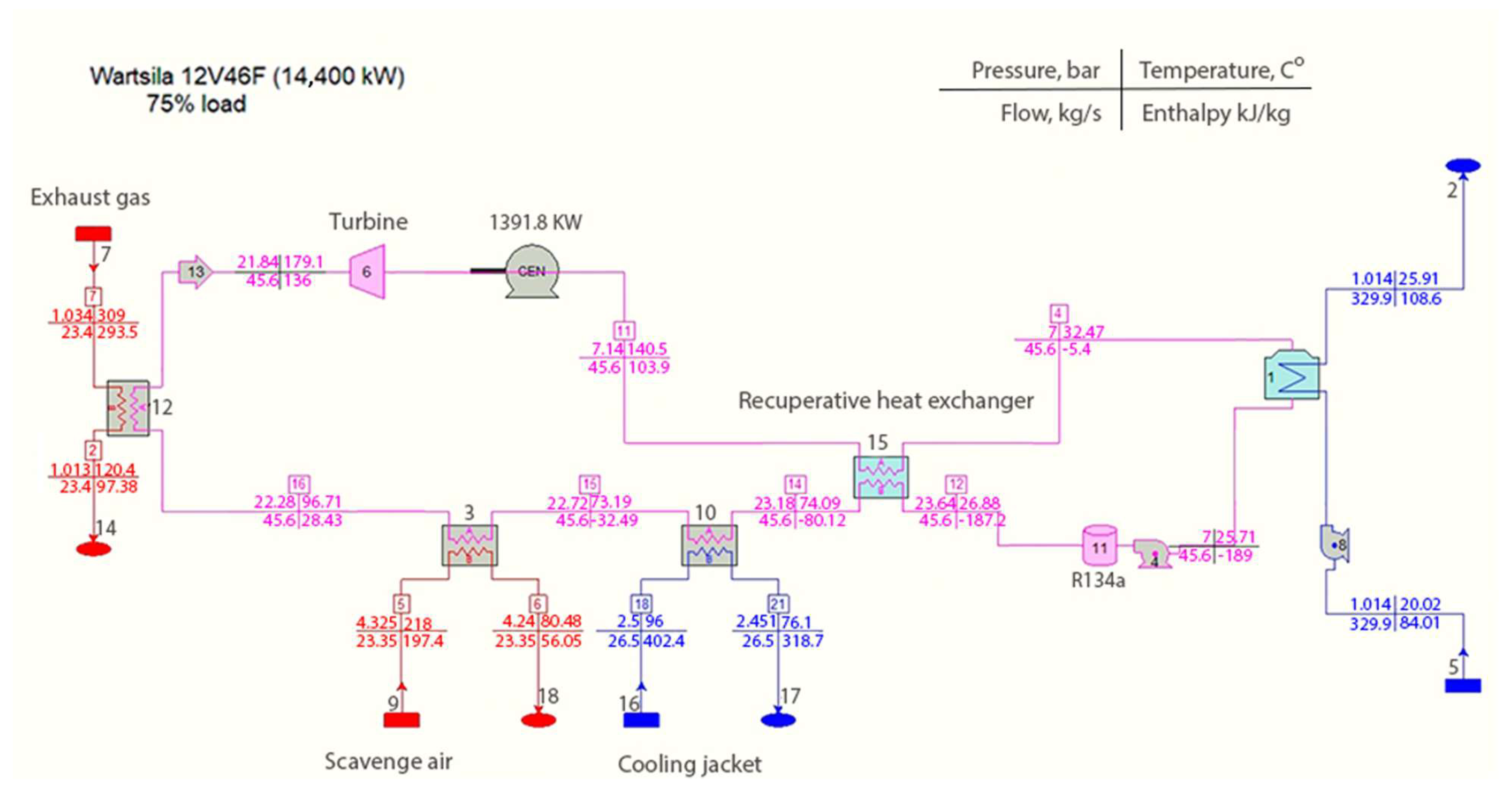
2.1. Formation, Justification, and Identification of the ORC Research Cycle Structure (Complex form of WHR Cycle with Different Heat Sources)

In the course of research, the main focus was on energy generation from secondary heat sources characteristic of ships in a single-stage organic Rankine cycle. To analyze and assess the operation of this WHR cycle system, a simulation model was developed using the thermodynamics software “Thermoflow version 31”. The first stage of the research was dedicated to evaluating the key aspects of ORC formation for the ship’s propulsion complex, utilizing the primary heat source—exhaust gases, which contain the maximum thermal energy of 28.9% of total fuel energy (scavenge air 14.2%, cylinder cooling jacket 9.7%). Comparative studies were conducted based on the use of this secondary heat source to assess different types of working fluids, identifying a more rational choice based on ship conditions. The research also aimed to evaluate energy efficiency and performance, considering different power turbine designs and control aspects [53]. Building on the resolved aspects of rational ORC utilization, the second stage of the research, presented in the author’s publication, is dedicated to comprehensive studies on different combinations of secondary heat sources (exhaust gases, internal cylinder cooling circuit, and scavenge air cooler) for ORC implementation. The thermal energy of secondary heat sources is converted into mechanical energy in the cycle’s power turbine, and this mechanical energy is transformed into electrical energy in the generator. This generated electrical energy can be utilized to improve the efficiency and sustainability of the ship, contributing to the EU goals of achieving emissions neutrality in maritime transport.
The numerical study simulation model scheme of the “Thermoflow version 31” software is presented in Figure 1.
The following components forming the schematic diagram of the WHR cycle are shown in Figure 1: 1—condenser; 2—outboard seawater discharge; 3—heat exchanger of the scavenge air circuit; 4—feed pump; 5—seawater intake; 6—turbine; 7—exhaust gas heat source; 8—seawater pump; 9—secondary heat source of the scavenge air cooler; 10—heat exchanger of the cylinder internal cooling circuit; 11—working fluid tank; 12—exhaust gas heat exchanger; 14—atmosphere; 15—recuperative heat exchanger; 16—flow from engine cylinder internal cooling circuit; 17—flow to the cylinder internal cooling circuit to the engine; and 18—supply of cooled scavenge air to the engine. The presented data of ORC parameters in Figure 1 are provided as an example of one of the many variations. All relevant data are presented in Appendix B, Table A3 and Table A4.
Figure 2 represents a p-h diagram illustrating the characteristic energy parameters and thermodynamic states of an organic Rankine cycle with a secondary heat source and Freon R134a working fluid. In the 1–2 segment, the working fluid (in liquid phase) pressure is raised to the required level corresponding to the turbine expansion parameters, directly linked to cycle efficiency. Upon reaching the set pressure, the primary heat supply into the cycle occurs from the RHE in the 2–3 segment, where the heat retained from the turbine outlet is transferred. At point 3, heat from the secondary heat source is supplied into the cycle. The working fluid is heated in the 3–4 segment, transitioning from unsaturated vapor to superheated vapor, thereby increasing cycle power and efficiency. Superheated vapors at point 4 reach the turbine, where expansion occurs until point 5, transforming heat into mechanical work. During this transformation, the turbine drives the generator and performs useful work, achieving cycle efficiency. After expansion in the turbine, the superheated vapor working fluid travels to the recuperative heat exchanger, where in the 5–6 segment, unused heat after the turbine is returned to heat the liquid phase of the working fluid, transitioning from superheated vapor to saturated vapor. In the condensation process in the 6–1 segment, the working fluid changes state from saturated vapor to saturated liquid, and the cycle repeats.
To increase the useful efficiency and energy efficiency, and optimize the ORC operation of the WHR cycle, an RHE is included in its structure (Figure 1, position 15). By using an RHE, it is possible to recover and utilize the waste heat in the cycle that would otherwise be discharged with the onboard water in the WF condenser.
The regenerative heat exchanger also has a secondary positive effect related to the auxiliary system of the WHR cycle, specifically the condenser (position 1). Due to the fixed degree of expansion of the turbine, the expansion ends at the superheated vapor region; therefore, a pre-cooler upstream of the condenser becomes necessary to cool the working substance in addition to the saturation temperature. This requirement would involve the need for an additional onboard water pump’s efficiency and additional energy costs for the WHR cycle to function. As the working substance passes through the RHE, it enters the condenser at a lower temperature, resulting in a reduced load on the onboard pump.
The ORC operates on the following principle (see Figure 1): The WF pressure is raised by the pump (position 4) to the working pressure, and the substance is fed to the recuperative heat exchanger (position 15). In the RHE, the WF is heated by the still-superheated vapor downstream of the turbine. The WF undergoes a phase change from saturated liquid to superheated vapor. From the RHE, the superheated vapor of the WF is directed to the secondary heat exchangers of the ship’s power plant, respectively, in increasing order of the heat source temperature: position 10—for the cylinder cooling circuit, position 3—for the scavenge air cooling circuit, and position 12—for the exhaust gas circuit. In these heat exchangers, the WF undergoes a phase change from superheated vapor to overheated vapor. The heat energy of the overheated WF vapor in the turbine (position 6) is converted into mechanical work P t u r b ; the turbine rotates the generator (position GEN), where electrical energy is generated, which is then used in the ship’s power plant propulsion system or according to the needs of electrical consumers (assessment of the energy cycle efficiency based on P t u r b , without considering further mechanical energy conversion into electrical energy by the turbine generator). In the form of vapor, the WF returns from the turbine to the RHE, where it releases some energy in heat form to the WF at the beginning of the cycle. The still-superheated vapor is directed to the condenser, where the WF is cooled by onboard water to the saturated liquid state, and the cycle repeats. The indicator of the WHR cycle’s energy efficiency is determined by the ratio of the useful effect P t u r b to the secondary heat source of the energy device Q S S .
The secondary heat sources can be included or disconnected from the cycle by appropriately adjusting the valves in the pipelines. In this structure, various possibilities for connecting and disconnecting heat sources during the cycle can be achieved, allowing for a rational adaptation based on the load regime and environmental conditions. The research in this study examines a sequentially connected heat exchanger scheme based on its simplicity of implementation.

2.2. Selection of ORC Working Fluid and Formation of Physical and Energetic Indicators

Based on the previously conducted research by the authors [53], Freon R134a was chosen as the working fluid, which demonstrated the highest energy efficiency among the tested wet, dry, and isentropic working fluids (Freon products R134a, R141b, R142b, R245fa, and Isopentane). The selection of Freon R134a refrigerant among all assessed working materials is based on the operational reliability of the cycle’s technological system concerning the fluid’s saturation pressure and temperature [53]. Also, the provisions of EU and IMO regulatory regulations on the use of Freon products in refrigeration technology and conditioning systems were taken into account.
The International Maritime Organization restricts the use of hydrochlorofluorocarbons in ship systems, which cause depletion of the ozone layer. On new ships from 1 January 2020, the MARPOL banned the use of hydrochlorofluorocarbons (HCFCs) in refrigeration installations. The ban is documented in Regulation 12 “Ozone-depleting substances” Annex VI to MARPOL 73/78 [54]. Moreover, HCFCs have additional drawbacks including significant global warming potential (GWP), which is another reason why their use is regulated.
According to the revised EU Regulation 517/2014 [55], from 1 January 2025 (with various exceptions until 1 January 2026), the use of fluorinated greenhouse gases with a GWP of 2500 or more for servicing and repairing all refrigeration equipment is prohibited. However, this ban will not come into effect until 1 January 2032, and will apply to regenerated fluorinated greenhouse gases with a GWP of 2500 or more used for technical servicing or repair of existing air conditioning and heating equipment. From 1 January 2032, the use of fluorinated greenhouse gases with a GWP of 750 or more (up to 2500) is prohibited, except for regenerated fluorinated greenhouse gases used in the repair and maintenance of refrigeration equipment. Thus, in EU ports and after 1 January 2032, for existing installations with a refrigerant having a GWP of no more than 2500, replenishment is possible solely through regenerated or recycled products. Among HCFCs with a GWP below 2500, for the most part, the single-component refrigerant Freon R134A and the blend R407F are used on ships with class registration [56,57]. Based on this, taking into account the EU regulatory restrictions, as well as the results of the authors’ first phase of research, Freon R134a with an ozone depletion potential of 1430 [55] was used for further research.
Based on the results of the initial research stage [53], for the operation of the KC, a “wet” type working fluid, Freon R134a, was chosen, and its properties are provided in Table 1.

2.3. Selection of the Research Object for ORC

To ensure a broad range of research, marine diesel engines chosen from the most popular engine manufacturers such as MAN B&W, Wärtsila, Sulzer, Cummins, and Hyundai were evaluated. Wärtsila is one of the leading companies in maritime technology, including environmental technology adaptation and development. According to the manufacturer’s statistical data for the year 2022 [58], medium-speed Wärtsila marine four-stroke diesel engines account for 44% of the total market. The widespread use of the manufacturer’s products in maritime transport is related to their known high reliability and efficiency, high fuel efficiency, flexible adaptation with a wide range of offerings, good environmental performance, service, and a solid reputation. Additionally, the increasing market share of four-stroke diesel engines is attributed to their attractive specific mass and size parameters, along with their existing close energy efficiency compared to two-stroke engines.
To conduct the research experiments of this study, the Wärtsila 12V46F four-stroke marine diesel engine was chosen due to its wide engine series and correspondingly broad nominal power ( P e ) range. The construction of this engine is analogous to models offered by other popular marine diesel engine manufacturers, which expands the applicability of the research results. The cross-section of the engine is shown in Figure 2 and the main engine parameter is provided in Appendix B, Table A1. Existing research on engines from this manufacturer has demonstrated realistic development prospects.
The manufacturer provides the specifications and a guide for this engine in accessible sources, where design data and the adaptation of marine diesel systems in installations can be found. In this guide, the engine’s technical specifications and key energy data are presented at 50%, 75%, 85%, and 100% load, while energy balance data are provided at 100% load only. When the engine operated at 25% load, energy parameters were modeled using the Impuls mathematical model.
Depending on the type of ship where the engine is installed, a specific operational cycle is determined for the engine. For example, ferry-type ships operate in the E3 operational cycle mode, and the main engine data are provided according to ISO 8178—Table 2.
The decision to use diesel fuel during engine operation was alternatively considered in studies alongside investigations into the energy efficiency of the engine operating with renewable and low-carbon-dioxide-generating fuel (LCA) types. With the onset of fleet decarbonization, its plans are linked to LCA expansion. According to experts, during the current to mid-2030s period, mainly next-generation biodiesels will be used, gradually transitioning to bio-LNG as LNG is replaced [59,60]. The expansion of ammonia and methanol in the fleet, related to infrastructure and necessary development aspects, is foreseen in later stages. In the absence of these fuel types developed in shipping (except for separate pilot study models), there is a lack of engine energy data essential for ORC studies [15,61]. Therefore, it is rational to limit comparative assessment to diesel, biodiesel, and LNG (Bio-LNG).
According to numerous scientific studies, due to relatively minor differences in chemical elemental composition compared to diesel (an increase of 1–11% in oxygen content at the expense of carbon), the components of the engine’s heat balance structure change insignificantly, accounting for approximately 3–4% in ORC studies.
The evaluations of LNG utilization were conducted based on the specifications of a Wartsila manufacturer’s engine, specifically the 12V46DF model, operating with two fuel types (diesel and LNG). When the engine switches from diesel to LNG operation, structural changes occur in the heat balance: heat generated by fuel combustion is regenerated into effective work, resulting in a 20% decrease in WHR cooling systems and a 10% decrease in charge air cooling. Additionally, as WHR from exhaust gases increases (due to the conversion from a heterogeneous to a homogeneous combustion model when switching to LNG), it increases proportionally. Therefore, it is reasonably anticipated that the energy cycle efficiency and corresponding energy efficiency indicators of the ORC will reach similar values with separate WHR regeneration, and their comprehensive adaptability to ORC will not cause changes affecting operation.

2.4. Mathematical Model of Numerical Studies of Engine Parameters

The energy balance calculation of the selected “Wärtsila” 12V46F engine was performed using classical combustion engine methods [53], relying on the results of energy parameter modeling.
For engine energy parameter modeling studies, a single-phase mathematical model was applied using the “Impuls” software. The choice of the “Impuls” program for research is based on its effective application in creating and modifying high-speed transport engines [53,58,62]. This software has been continuously improved by adding secondary models to assess fuel and air mixture formation and combustion, fuel injection dynamics, vaporization, flame propagation, and different chemical compositions of fuel. Many phenomenological sub-models implemented in this program share similarities with another widely used software, “AVL BOOST 2023R2” [63]. The main version of the program includes 18 secondary models allowing the simulation of closed-cycle diesel engine models with a turbocharger. This modeling is based on quasi-static thermodynamics and gas equations, taking into account various factors such as design parameters of the exhaust system, variable efficiency coefficients of the gas turbine and compressor, heat losses to the engine cooling system, and environmental air parameters. These software tools provide methodological foundations for modeling and analyzing engine performance based on the principle of energy balance sustainability (differently from multi-zone models). The continuous improvement in the program and the integration of advanced sub-models contribute to the progress of engine technologies and a better understanding of the complex engine processes.
The algorithm of the model simulates the closed energy cycle model of a diesel engine with a turbocharger. It is based on quasi-static thermodynamics and gas equations, considering the design parameters of the exhaust system, variable efficiency coefficients of the gas turbine and compressor, heat losses to the engine cooling system, and environmental air parameters. The processes occurring in the engine cylinder are described by a system of differential equations, consisting of the first law of thermodynamics equation (Equation (1)) (energy conservation law), the mass conservation equation of the working substance (Equation (2)), and the state equation of the working substance (Equation (3)):
d U d τ = d Q r e d τ d Q e d τ p · d V d τ + h s · d m s d τ h e x · d m e x d τ , [ kJ / s ]
d m d τ = d m s d τ + d m i n j d τ d m e x d τ , [ kg / s ]
d p d τ = m · R V · d T d τ + m · T V · d R d τ + R · T V · d m d τ p V · d V d τ , [ Pa / s ]
where U —internal energy of the working substance within the engine cylinder, kJ; τ —time, s; Q r e —the rate of heat transfer into the system (energy added to the system through heat), kJ/s; Q e —the rate of heat transfer out of the system (energy removed from the system through heat), kJ/s; p —pressure within the engine cylinder, Pa; V —volume of the engine cylinder, m3; h s —specific enthalpy of the working substance entering the system, kJ/kg; m s —mass flow rate of the working substance entering the system, kg/s; h e x —specific enthalpy of the working substance exiting the system, kJ/kg; m e x —mass flow rate of the working substance exiting the system, kg/s; m —total mass of the working substance within the system, kg; R —ideal gas constant, measured in J/(kg·K); T —temperature within the engine cylinder, K; and d m i n j —mass flow rate of injected substance (fuel), kg/s.
The heat release was determined using the Wiebe model [64] with G. Woschni’s additions [65,66], which are widely applied in studies modeling internal combustion engine working processes [67,68]. The “TEPLM” software was used for experimental indicator analysis. It employs a closed thermodynamic cycle energy balance model to evaluate heat transfer through the cylinder walls.

2.5. Calculation of the Energy Balance during the Operation of the Diesel Engine in the Operational Characteristic Modes

The energy balance of the engine is one of the most important factors in evaluating the operation of a WHR system because the energy results of the cycle depend on it. The freely available specification of the “Wärtsila” 12V46F diesel engine has been used to form energy indicators. The provided specification data for the P e range of load modes are limited (data are provided for 100% load) and do not include all secondary heat sources. Therefore, to assess the use of the WHR cycle over a wide range of load modes, energy balance parameter calculations for the missing data of the WHR cycle were performed, simultaneously aligning them with the engine specification. Calculations were performed with the engine operating in propulsion mode and presented in a logical sequence. The relevant balance of secondary heat sources for the WHR system consists of the heat values of exhaust gases, scavenge air cooling, internal cylinder cooling, and lubrication system cooling and are presented in Equation (4):
Q S S = Q e x h . + Q s c . a i r + Q c i l + Q o i l
Based on the classic structure of the ship’s cooling and lubrication system, the heat components Q o i l   ( k J / s ) and Q W   ( k J / s ) in the ORC modeling cycle are the integral parts of the cylinder block cooling balance and are combined into a single secondary heat source. Finally, the variations examined include the heat source of exhaust gases, scavenge air, and the cylinder cooling (along with Q o i l   ( k J / s ) ). The calculations were performed using classical calculation methods and the results are presented in Appendix B, Table A2.

2.6. ORC Energy Efficiency and Its Structure Unit Parameters

During numerical simulations, useful efficiency coefficients, η , are evaluated, reflecting the efficiency of the WHR cycle. The energy efficiency indicators of ORC utilization on a ship include the following:
η e —ship powerplant efficiency,
η e R C —ship powerplant efficiency with ORC,
η R C —ORC efficiency,
η e R C c i k l —ship power plant efficiency with ORC with ISO 8178 operational cycle.
The assessment of different organic working fluids in the Rankine cycle is carried out based on the change in the energy efficiency indicator of the engine. The effective δ η e R C efficiency coefficient (EE) stands for the relative increase/change in engine power with and without ORC. The useful efficiency coefficient η e of the ship’s power plant indicates the part of the energy effectively utilized compared to the amount of fuel energy used in the technological process. Two analytical expressions of η e R C are used to assess the efficient operation of the WHR cycle:
  • Evaluating how much the effective useful coefficient η e R C of the main engine increased with the WHR system cycle, using secondary heat in it to generate electrical energy.
  • Evaluating the efficiency of energy use in the WHR cycle itself η R C .
The useful efficiency coefficient of the ship’s power plant indicates how efficiently the thermal energy of the fuel is used to perform useful work. The EE of the engine without the WHR system is calculated using the ICE theory classical Equation (5):
η e = P e H u · G f
The cycle with heat input from three secondary heat sources is examined as follows:
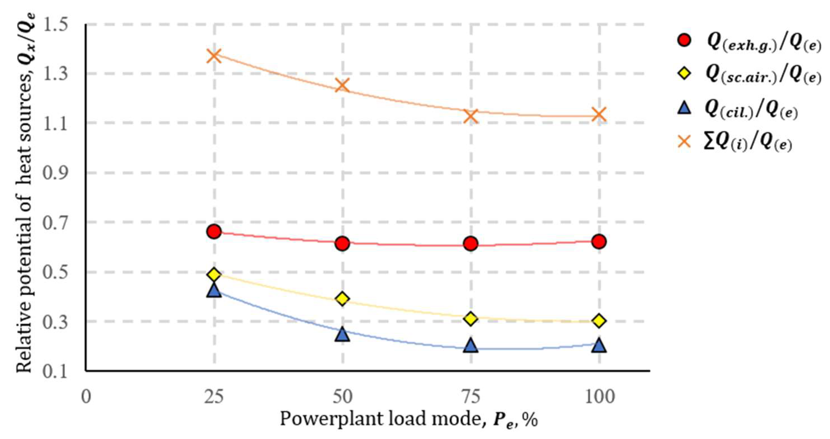
  • Exhaust gas secondary heat source;
  • Internal cylinder cooling circuit secondary heat source;
  • Scavenge air cooling circuit secondary heat source.
Determination of η e R C for a power plant with an organic Rankine cycle with all three heat sources is presented in Equation (6):
η e R C = ( P t u r b + P e ) H u · G f
P t u r b is formed from the supplied heat from the three secondary heat sources according to Equation (7):
Q = Q e x h . + Q c i l . + Q s c . a i r = Q f · q e x h . · η t . e x h . · Ψ t . e x h + Q f · q c i l . · η t . c i l . · Ψ t . c i l . + Q f · q s c . a i r · η s c . a i r · Ψ t . s c . a i r
Here, η t . c i l and η s c . a i r are the thermal efficiency coefficients of the heat exchangers, Ψ t . c i l and Ψ t . s c . a i r are energy utilization factors (similar to the case of exhaust gases and expansion turbines) for decreasing temperatures in the heat exchanger to the level specified in the engine specifications: inflatable air—up to 50 °C; cylinder cooling circuit—up to 75 °C.
In general, secondary heat sources form P t u r b as described in Equation (8):
P t u r b = Q ( η t . a d · η m · Ψ t u r b )
where Q is the heat supplied to the turbine. Heat transformations also occur in the turbine, Ψ t . c i l = h w 1 h w 2 h w 1 h w , when h w 1 h w 2 results in a real decrease, and the h w 1 h w decrease is necessary according to the specification.
The energy utilization factor for inflatable air is evaluated similarly. The specific heat of secondary heat sources is described by Equations (9) and (10):
q c i l . = Q c i l . H u · G f ,
q s c . a i r = Q s c . a i r H u · G f
Fuel heat release during combustion in the engine is described by Equation (11):
Q f = H u · G f
It is expedient to describe P t u r b in two forms.
The power equation of the turbogenerator, in terms of the efficiency of the WHR cycle, is described by Equation (12):
P t u r b = ( Q e x h · η t . e x h · Ψ e x h + Q c i l · η t . c i l · Ψ c i l + ( Q s c . a i r · η t . s c . a i r · Ψ s c . a i r ) ) · η t . a d · η m · Ψ t u r b .
The utilization coefficient of secondary heat sources Ψ i is one of the essential parameters determining the utilization of enthalpy and temperature of the sources in the cooling circuits of cylinders and the cooling circuit of the compressed air up to the values regulated by the engine manufacturer. This includes the temperature of the exhaust gases relative to the dew point temperature of the exhaust gases, aiming to avoid sulfuric acid condensation in the exhaust tract when the engine operates with sulfur-containing fuel. The parameter Ψ = 1,0 , for the exhaust gas heat source could be considered when the temperature of the exhaust gases decreases to the air temperature at the engine intake (i.e., 50 °C). However, in such a case, the system does not ensure conditions related to the concentration of H 2 S O 4 . Therefore, alternatively, it is assumed that Ψ = 1,0 , when the temperature decreases to the dew point.
The relative efficiency coefficient parameter Ψ t u r b . of the turbogenerator illustrates the ratio of the actual decrease in the working substance’s enthalpy in the turbogenerator to the potential decrease in enthalpy down to the boiling temperature. The efficiency of the turbine is characterized by the adiabatic efficiency parameter η T a d and the mechanical efficiency parameter η m . Expressing Q = G f × H u × q and P e = G f × H u × η e 3600 , we obtain Function (2.15) in terms of the dimensionless quantities.
As a result, the overall efficiency of the power plant with an organic Rankine WHR cycle, introducing three secondary heat sources, is determined by the Formulas (13) and (14):
η e R C = P e + Q ( η t . a d · η m · Ψ t u r b ) H u · G f
η e R C = [ η e + ( q e x h · η t . e x h · η t . e x h + q c i l · η t . c i l · η t . c i l + q s c . a i r · η s c . a i r · η s c . a i r ) · ( η t . a d · η m · Ψ t u r b ) ]
ORC cycle efficiency is determined by Equation (15), respectively:
η R C = H u · G f ( q e x h · η t . e x h · Ψ t . e x h + q c i l · η t . c i l · Ψ t . c i l + q s c . a i r · η s c . a i r · Ψ s c . a i r ) · ( η t . a d · η m · Ψ t u r b ) H u · G f ( q e x h + q c i l + q s c . a i r )
Then, using the P t u r b evaluation form to identify and improve the factors influencing the efficiency of the WHR cycle, the operational parameters of the cycle power turbine can be optimized and their relationship with a rational choice can be determined.
The power generated in a propulsion turbine is defined by Equation (16):
P t u r b = G w m ( h t g 1 h t g 2 )
The turbine nozzle apparatus design is indicated by the parameter π T , which shows the degree of pressure reduction (the pressure ratio before and after the turbine) of the WF before and after the turbine. The power generated in the turbogenerator is also expressed by Equation (17):
P t u r b = G W F · t W F 1 · c p W F [ 1 π T K 1 K ] · η t . a d · η m · β
β —energy input impulse coefficient, which is 1,0 under WHR cycle conditions;
k —specific heat ratio.
Then, the change in the total generated mechanical energy of the engine’s cycle, taking into consideration the generated P t u r b , is expressed by Equation (18):
δ η e R C = ( η e R C η e 1 ) = ( P e + P t u r b H u · G f P e H u · G f 1 ) = P t u r b P e ;
In order to identify and improve the factors influencing the efficiency of the WHR cycle, the operational parameters of the turbogenerator can be optimized and their relationship with a rational selection can be determined.
We evaluated the WHR cycle efficiency, η R C , and determined how efficiently the secondary heat sources are transformed into the turbine mechanical work and further converted into electricity in the generator.

3. Results

In the ship’s power plant, various secondary heat sources with different temperatures and heat quantities prevail. Heat sources with an average quality are considered when their temperature is ≥230 °C. At such temperatures, the utilization of thermal energy is not complicated and is typically employed in steam boilers. However, the utilization of low-quality secondary heat sources (temperature—30–200 °C) in steam boilers is challenging, and they are often ignored. On the other hand, WHR systems with an organic Rankine cycle open up possibilities for the utilization of low-temperature secondary heat sources. In ship power plants, a wide range of secondary heat sources is present, with the majority of energy being lost through exhaust gases, which can reach temperatures of 220–400 °C. In modern marine diesel engines, the waste heat dissipated by the compressed air cooler is slightly lower than the temperature of the exhaust gases, which can range from 170–250 °C. The third in size is usually the internal cylinder cooling circuit of the engine, with a temperature ranging from 75–95 °C in modern diesel engines. The heat quantity from other sources (oil cooling, heat radiation, etc.) is not significant, making their rational use impractical.

Complex Form WHR Cycle with Different Heat Sources

Comparative numerical studies of the cycle energy efficiency were conducted using different combinations of individual and complex secondary heat sources. The secondary heat sources were supplied in a sequential order in the WHR cycle structure, from the lowest temperature to the highest. Finally, the heat supply to the cycle was carried out in the following order: supply of heat from the cylinder cooling circuit (96 °C) → supply of heat from the compressed air cooler (220 °C) → supply of heat from the exhaust gases (364 °C). The cycle combinations were implemented using the working fluid Freon R134a, with which the best energy efficiency parameters were achieved in a wide power plant range in the first stage of dissertation research. This substance is also widely used in land-based cogeneration plants. The expansion of the working fluid in the cycle and the mechanical work were ensured by a turbo-generator with a variable geometry turbine, which achieved 25–30% better results than the results of the first stage of the research with a turbine with a fixed geometry. The results of individual secondary heat sources in ORC are presented in Appendix B, Table A3.
The obtained results of the engine’s energy balance calculation indicate the distribution of heat source quantities, where Q c i l . < Q a i r Q c i l . + Q a i r   Q e x h . g . , demonstrating the importance of low-temperature sources. Typically, the heat potential is evaluated based on the ratio of energy supplied with fuel. However, when evaluating a variable and wide power plant load range, it is more rational to assess it based on the power of the plant under the corresponding load conditions. A graph (Figure 3) depicting the heat quantity ratio between secondary heat sources and the engine’s effective power allows for the assessment of each source according to the P e characteristic.
The highest heat potential, especially under low and moderate load conditions, is associated with the use of a variable geometry turbine in the WHR cycle [53]. To assess the attractiveness of each secondary heat source, experimental studies were conducted on the variation in individual heat sources in the WHR cycle, and the results obtained are presented graphically as follows:
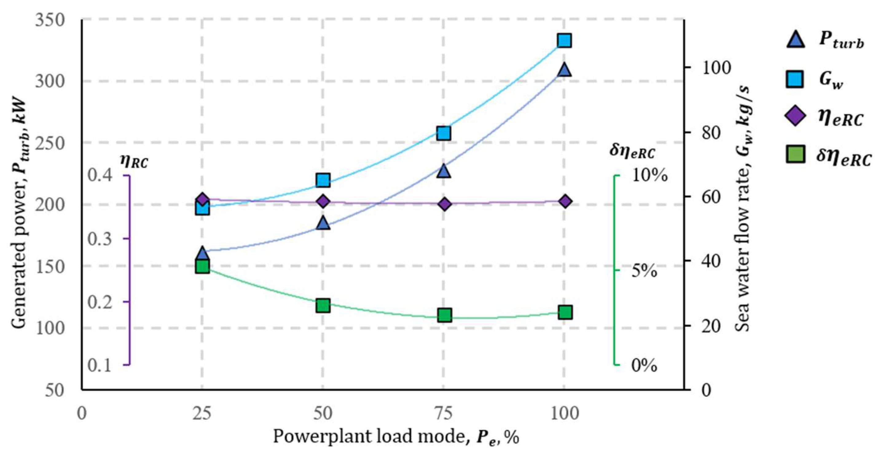
  • The power generated by the secondary internal cylinder cooling circuit heat source P t u r b in the WHR cycle ranges from 160 kW to 310 kW. The seawater flow rate for condensation ranges from 55 kg/s to 108 kg/s, corresponding to load conditions of 25–100% of the engine, at a seawater temperature of 20 °C. Graphically, it can be observed that the most significant change in the WHR system’s useful efficiency coefficient is achieved under low load conditions (Figure 4).
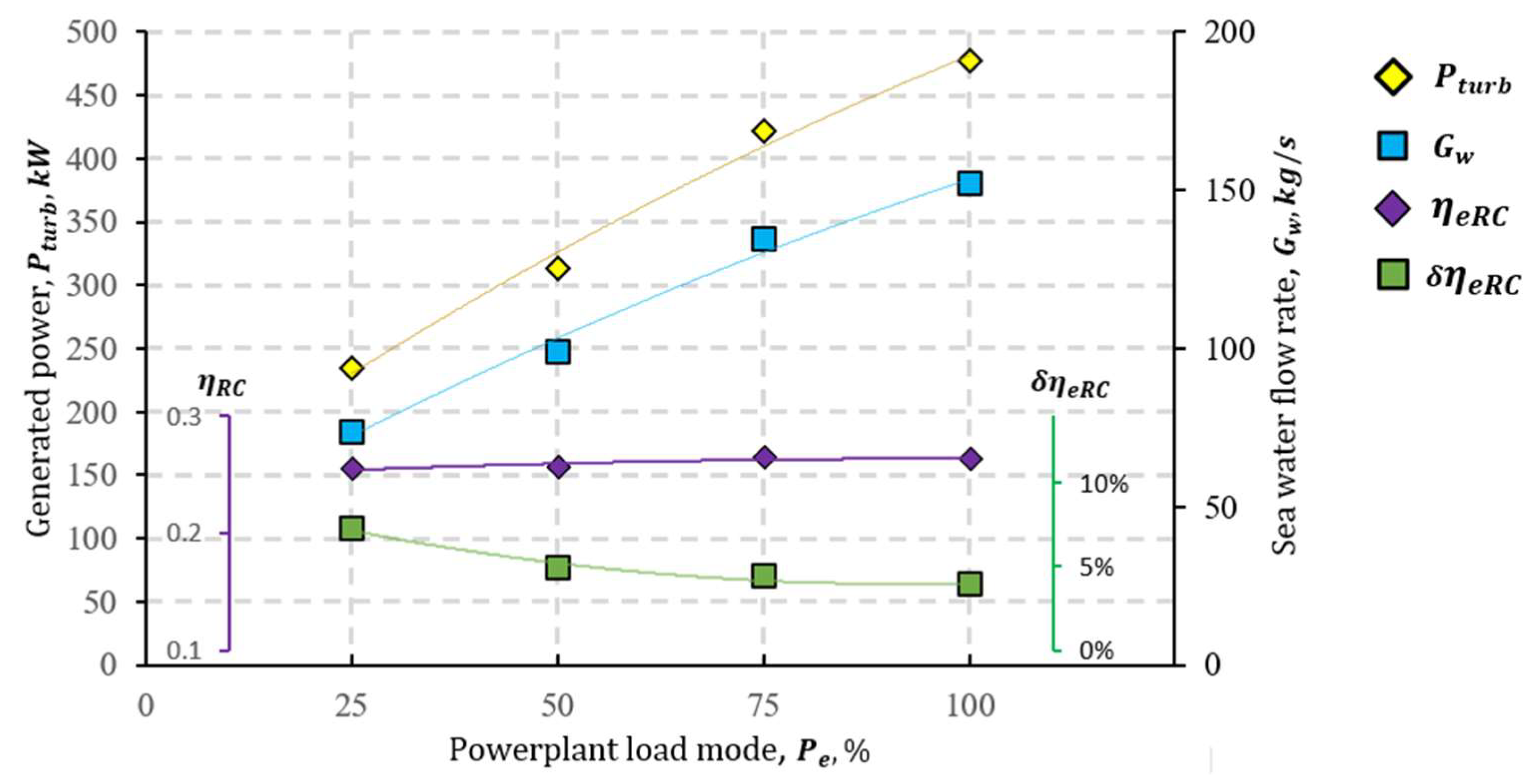
  • The power generated by the secondary scavenge air cooling circuit heat source ( P t u r b ) in the WHR cycle is higher than that of the cylinder cooling circuit, ranging from 234 kW to 477 kW. The seawater flow rate for condensation ranges from 74 kg/s to 152 kg/s, corresponding to load conditions of 25–100% of the engine, at a seawater temperature of 20 °C. Graphically, it can be observed that the most significant change in the WHR system’s useful efficiency coefficient is also achieved under low load conditions (Figure 5).
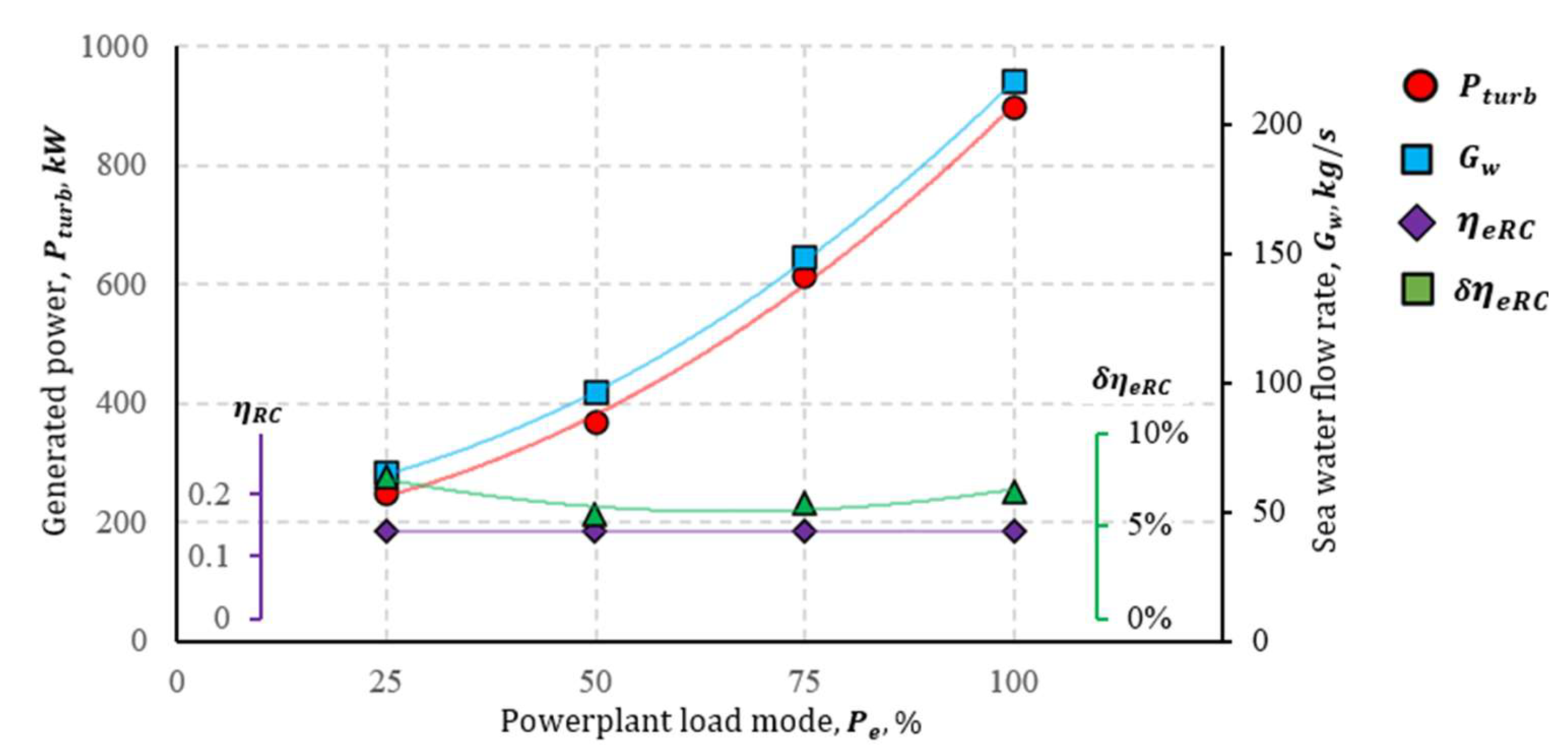
  • The power generated by the secondary exhaust gas circuit heat source P t u r b in the WHR cycle, under low load conditions, is slightly lower than the compressed air source, producing 249 kW. However, when there is a high load, the generated power is almost twice as much as the compressed air source, reaching 898 kW. The seawater flow rate for condensation in the cycle varies from 74 kg/s to 152 kg/s, corresponding to load conditions of 25–100% of the engine, at a seawater temperature of 20 °C. Graphically, it can be observed that the greatest positive change in the useful efficiency coefficient of the WHR system is achieved under low load conditions (Figure 6).
Based on the obtained results, it is noted that supplying a higher amount of heat (exhaust gas > compressed air heat > cylinder cooling circuit heat) results in higher system efficiency and a greater positive change in the WHR system’s useful efficiency coefficient. In all cases, there is an observed relationship between efficiency and the seawater flow rate, which can be a crucial limitation when choosing the heat source in the WHR cycle. The results of the complex secondary heat source in ORC are presented in Appendix B, Table A4.
The results of the numerical variational studies allow for the formulation of methodological foundations for the WHR cycle structure. The results of studying various heat source options in the WHR cycle demonstrate a direct connection between the power generated by the turbine P t u r b and the seawater flow rate G w , which is used to condense the WF. The evaluation of G w is important in the context of assembling the WHR cycle structure because it is related to the selection of seawater pumps; thus, it is rational to assess the inclusion of ballast purpose pumps already used on the ship in the auxiliary condensation system of the WHR cycle, considering their efficiency and thus saving costs and space for separate pumps.
In the case of technological feasibility, the ballast (or other) pumps of the ship could ensure the inflow of board water into the condenser, thus saving space on the ship and project costs. According to statistical data, the average efficiency of ballast water pumps for a research ship’s propulsion engine “Wärtsila” 12V46F, of a similar size, in the operating fleet and manufacturer specifications, ranges from 300 to 600 m3 per hour. To ensure the condensation of the working fluid in the WHR cycle without the efficiency of ballast pumps, it is necessary to use separate board water pumps. Looking at the statistical data of the “DESMI” pumps widely used in practice, the maximum proposed pump flow for ORC operation is 6000 m3/h (see Appendix B, Figure A1), or when converted to mass units—1667 kg/s. However, the use of pumps with such efficiency on board is complicated due to mass and size limitations.
Therefore, the maximum flow rate becomes another limiting factor for the energy generated by the ORC. To optimize the generated mechanical energy, P t u r b , the energy efficiency indicators η R C , δ η e R C , and G w , a mathematical modeling experiment, and theoretical solutions are used to establish a connection between P t u r b and G w .
The establishment of analytical expressions between P g e n and G w is based on the heat balance equation of the WHR cycle. The energy balance of the WHR cycle, expressed in a generalized form, is given by energy balance in the form of heat as follows:
Q h = Q T + Q w ,   or ,   per   unit   mass   of   WF ,
G W F q h = G W F · q T + q w G W F ,
where:
Q h —total heat transferred per unit mass of working fluid.
q h —specific WHR heat transferred per unit mass of the working fluid in the heat exchanger (heat exchange in the regenerative heat exchanger is not considered in the balance due to the assumed equality between the heat transferred and received by the working fluid in the RHE).
q t —energy, in the form of specific heat, transformed into mechanical work in a power turbine.
q w —transferred specific heat from the working fluid to the overboard water.
On the other hand, the energy balance in the condenser is G W F · q w = q w G w , or G W F · q w = q w G w , where q w is gained heat from seawater cooling, and G w is the seawater flow rate (heat losses in the condenser are not estimated). As a result, the formula G W F · q S S = G W F · q T + q w G w is derived.
Substituting G W F q T to G W F q S S · K 1 (where K 1 is the cumulative efficiency of the power turbine), the energy balance equation transforms into the expression G W F · q S S = G W F · q S S · K 1 + q w G w , and after simplification into the following form:
G W F · q S S G W F · q S S · K 1 = 1 + q w G w G W F · q s s · K 1 = 1 + q w G w Q T ,
G W F G W F · K 1 = 1 + q w G w Q T = 1 K 1
Since for the evaluated technological embodiment of the WHR cycle power turbine indicators K 1 and q w (when T w = c o n s t . ) are evaluated as constants, the constant is also the ratio G w Q T .
Equation (22) is characterized by universality, making it applicable to any combination of secondary heat sources if Q R H E is sufficient to heat the working substance to the beginning of vaporization in the WHR cycle, which occurs in the recuperative heat exchanger. Otherwise, the condition G w Q T = c o n s t is specific to a particular regeneration variant. This characteristic is revealed in Figure 7, which shows individual graphs of G w P t u r b for internal water circuit and air cooling heat regeneration, and the heat regeneration of exhaust gases both separately and in combination with other heat sources, are characterized by the same G w P t u r b dependence, which is graphically represented in Figure 7.
The obtained result provides a theoretical basis to standardize the principles of forming a rational structure for the WHR cycle. This involves evaluating the potential of secondary heat sources in the context of the research engine module and its connection with the technological constraints of shipboard water systems. Methodological aspects and the logical sequence of the research are presented schematically in Appendix A, Figure A1.

4. Conclusions

In order to systematize the rational selection of low-temperature (internal cylinder and scavenge air cooling circuits) and high-temperature (exhaust gas) secondary heat sources in a WHR cycle for energy efficiency priorities, complex, analytical, and numerical variations were carried out in a study of the medium-speed diesel engine “Wärtsila” 12V46F’s organic Rankine cycle (ORC) with Freon R134a working fluid within the operational range of 25–100% engine load according to the ISO 8178 E3 cycle.
Compared with the practical applicability of a single heat source ORC in a marine environment, the comprehensive potential for utilizing secondary energy to increase ship power plant engine efficiency η R C was evaluated up to 13.5–21% in the range of 100–25% load modes. The obtained results for the external heat balance structure typical for a main medium-speed diesel engine can be summarized as follows:
  • The rational distribution of ORC heat exchangers based on the increasing characteristic temperature of secondary heat sources (operating in the range of 25–100% engine load, engine cooling jacket, scavenge air, and exhaust gas WHR secondary heat cooling circuits) ensures close proximity to the energy potential of the heat sources: internal cylinder cooling circuit—95%; scavenge air cooling circuit—84%; and exhaust gases—99% (with Ψ 1,0 );
  • The results indicate that it is rational to use ORC throughout the typical operational range of the engine, as reducing the nominal power from 100% to 25% leads to an improvement in the effective efficiency increase using ORC δ η e R C as follows: WHR for exhaust gases from 6.9% to 7.7%; charge air cooling circuit from 4% to 7.3%; and cylinder block cooling circuit from 2.8% to 5.2%.
  • Specifically, the high efficiency of increasing η e R C at low engine loads determines the most crucial operational δ η e R C average values for the entire load cycle, respectively, 6.6%; 4.8%; and 3.1%.
  • The comprehensive composition of a WHR system with various combinations ensures δ η e R C c i k l increase over the operational load cycle ranging from 14.8% (all three secondary heat source WHR cycle) to 3% (only low-temperature WHR cycle).
  • Attention is drawn to the relatively high energy efficiency of the implementation of the scavenge air cooling WHR system—the difference in δ η e R C compared to exhaust gas WHR is only about 1.5%: approximately ~5% versus 6.5%, respectively. In combination with a relatively straightforward technical implementation, this allows considering this WHR as one of the effective components of the ship engine’s ORC, both in its standalone and combined applications with other WHR systems.
  • ORC variation study data indicate that the application of secondary heat sources in the marine power plant in the operational characteristic range alternatively ensures the total power plant efficiency and improves energy performance. Variations in the complex use of exhaust gases, internal cylinder cooling circuit, and scavenge air cooler heat guarantee P t u r b 500 1842   k W , δ η e R C 21.4 7.0 % , indicator values.
  • In pursuit of complex heat source application in the cycle, an experimentally identified and analytically supported linear relationship between the cycle’s energy efficiency P t u r b and the efficiency of the condensation system’s pump ( G w ) is established. Based on this, the selection of ORC heat source complex utilization strategies is limited by data from one of the sources and is evaluated in terms of the technologically achievable efficiency of G w pumps in relation to P t u r b .
Based on the conducted comprehensive analytical studies and expanded numerical experiments, the main task of the next stage of ongoing research is related to formulating the methodological principles for the rational application of ORC in marine power plants. The practical implementation of these principles constitutes the main objective of the current phase of our research.

Author Contributions

Conceptualization, S.L.; methodology, S.L.; software, T.Č.; validation, T.Č.; analysis, S.L. and T.Č.; investigation, S.L.; data curation, S.L. and T.Č.; writing—original draft preparation, S.L. and T.Č.; writing—review and editing, S.L. and T.Č.; visualization, T.Č.; funding acquisition, T.Č. All authors have read and agreed to the published version of the manuscript.

Funding

The project was financed by Research Council of Lithuania and the Ministry of Education, Science and Sport Lithuania (Contract No. S-A-UEI-23-9).

Institutional Review Board Statement

Not applicable.

Informed Consent Statement

Not applicable.

Data Availability Statement

Data is contained within the article.

Acknowledgments

The authors are grateful to the company “Thermoflow Inc” for the thermal engineering software “Thermoflow” and the possibility to run cycle simulations for the experimental research. The authors are grateful to the developers of the thermal engineering software “Thermoflow” for the opportunity to run cycle simulations for the experimental research.

Conflicts of Interest

The authors declare no conflicts of interest.

Correction Statement

This article has been republished with a minor correction to the Funding statement. This change does not affect the scientific content of the article.

Nomenclature

b e Specific fuel consumption, g/kWh.
c p W F Specific isobaric heat of the working fluid, kJ/(kgK).
G a i r Charge air flow before entering the engine cylinder, kg/s.
G W F Flow rate of working fluid, kg/s.
G f Hourly engine fuel consumption, kg/s.
G w Seawater flow rate, kg/h.
H u Lower fuel calorific value, kJ/kg.
h t g i Enthalpy of the working material before and after the turbogenerator, kJ/kg.
h w 1 ;   h w 2 Enthalpy of the working before and after cylinder cooling jacket heat exchanger, kJ/kg.
h w Enthalpy value which is necessary according to engine manufacturer specification, kJ/kg.
k Specific heat ratio.
K 1 The cumulative efficiency of the power turbine.
nrevolutions, min1.
pPressure, Pa
P e Main engine power, kW.
P t u r b The power generated by the turbogenerator of the WHR system, kW.
t W F 1 The temperature of the working fluid, °C.
T e x h . g . Exhaust gas temperature, °C.
Q e x h . Power plant exhaust gas energy part of heat balance, kJ/s.
Q f Total fuel energy, kW.
Q s c . a i r Power plant scavenges air cooling energy part of heat balance, kJ/s.
Q o i l Power plant lubricating oil cooling energy part of heat balance, kJ/s.
Q c i l . Power plant cylinder cooling jacket energy part of heat balance, kJ/s.
Q w WHR cycle heat dissipation through overboard water, kJ/s.
Q h Total heat transferred per unit mass of working fluid, kJ/s.
Q S S Secondary heat source transferred heat, kJ/s.
Q T Transformed heat in the turbine into mechanical work, kJ/s.
q e x h . ;   q c i l . ;   q s c . a i r Specific heat of secondary heat sources, kJ/kg.
q h Heat transferred from the working substance to the condenser, kJ/kg.
q S S Transferred specific heat from secondary heat sources to WF, kJ/kg.
q w Transferred specific heat from the working material to the overboard water kJ/kg.
q w Gained heat from seawater cooling.
π T The degree of pressure drop in the turbine.
T e x h . g . Exhaust gas temperature, °C.
η e Coefficient of performance of the main power plant.
η e R C The total coefficient of performance of the ship’s main power plant with a WHR system.
η R C Coefficient of performance of the WHR cycle.
δ η e R C Relative change in ship power plant efficiency with and without ORC.
η e R C c i k l Ship power plant efficiency with ORC with ISO 8178 operational cycle.
η t . s c . a i r ;   η t . c i l . ;   η t . e x h . Thermal efficiency coefficient of the secondary heat source exchangers.
η t . a d Internal (adiabatic) efficiency of the turbogenerator.
η m Mechanical efficiency of the turbogenerator.
Ψ t . c i l ;   Ψ t . s c . a i r ;   Ψ t . e x h Energy utilization factors of secondary heat sources.
β pulse energy input factor.
t W F 1 Temperature of the WF before the turbine, °C.
Abbreviations
CIICarbon intensity indicator
CO2Carbon dioxide
EEEfficiency coefficient
EEDIEnergy efficiency design index
EEXIExisting energy efficiency index
EUEuropean Union
GHGGreenhouse gases
GWPGlobal warming potential
HCFCHydrochlorofluorocarbons
IMOInternational Maritime Organization
LCALow-carbon-dioxide-generating fuel
MARPOLInternational Convention for the Prevention of Pollution from Ships
MEPCMarine Environment Protection Committee
ORCOrganic Rankine cycle
SRCSteam Rankine cycle
RHERecuperative heat exchanger
WFWorking fluid
WHRWaste heat recovery

Appendix A

Figure A1. Block algorithm for the formation of the cogeneration cycle structure and identification of parameters [53].
Jmse 12 00521 g0a1

Appendix B

Table A1. Research object “Wärtsila” 12V46F main engine general parameters.
ParameterDataDimension
Manufacturer, typeWÄRTSILA 12V46, trunk type-
Year of manufacture2008Year
Piston stroke580Mm
Average piston speed9.7m/s
Cylinder diameter460mm
Number of cylinders12vnt.
Nominal power12,000kW
Possibility of reversalNon-reversal-
Type4 stroke-
Number of valves48pcs.
Crankshaft
revolutions
350–600rpm
Type of fuel usedIFO 380 heavy fuel oil, diesel-
Compression pressure56bar
Maximum combustion pressure135bar
Specific fuel
consumption
174g/kWh
Table A2. Energy balance indicator calculation results.
Load Mode %
100%85%75%50%25%
P e , cil. kW12001020900600300
G f , kg/s0.720.590.550.380.20 *
η e 0.4690.4830.4590.440.425 *
ϵ 2.52.682983.383.8 *
G a i r , kg/s26.123.3523.3518.814.5 *
ρ a i r , kg/m34.514.264.444.13.98 *
P K , bar4.244.014.173.863.75
t g , °C366316309273255 *
P K , bar4.454.24.384.063.93
t k / c p , °C220211
218
205
200
29.34429.32429.3429.31129.3
M 1 , mol1.251.341.491.691.9
M C O 2 , CO2 kg fuel0.0725
M H 2 O , H2O kg fuel0.063
M O 2 , O2 kg fuel0.1560.1740.2060.2480.291
M N 2 , N2 kg fuel0.991.061.181.3381.51
M 2 , mol1.281.371.521.721.996
m C V , kj/kmolK20.795
m C p , kj/kmolK29.11
m C V , kj/kmolK22.3122.1121.9321.6721.46
m C p , kj/kmolK30.6330.4330.2529.9629.78
Q e x h . g . , kW89906622662244112387
Q f , kW30,74425,19323,48516,2268540
Q e , kW14,40012,24010,80072003600
Q s c . a i r , kW43693629385128141010
Q c i l + Q o i l , kW29852702221218011543
Q r a d , kW420Not applicable
* extrapolation.
Table A3. Individual secondary heat source in ORC results.
EXHAUST GAS
Working MaterialLoad, %Working Fluid Enthalpy (pos. 12), kJ/kgExhaust Gas Temperature (pos. 12), CWorking Material Temperature (pos. 6)Working Fluid Enthalpy (pos. 6), kJ/kgWorking Material Flow, kg/sPressure, Bar (pos. 6)Pressure decrease Ratio (in Turbine, pos. 6)Power, kWScavenge Air Temperature (pos.3)Scavenge Air Flow, kg/sCylinder Cooling Temp. (poz 10)Cylinder Cooling Flow, kg/s η e δ η e R C η e R C c i k l η R C Ψ t . e x h Ψ t . s c . a i r Ψ t . c i l
R134a100−86.16132.3364123.2179.5137.3132.3100.529.521.847.143.059897.7N/AN/AN/AN/A0.4696.87%0.480.1420.994N/AN/A
75−86.17132.3309121.5175.9137.3132.3100.520.321.847.143.059613.60.4596.25%0.1420.994
50−86.18132.3273121.3175.9137.3132.3100.513.1521.847.143.059367.70.445.66%0.1420.992
25−86.16132.3255121.7175.9137.3132.3100.58.921.847.143.059248.70.4257.65%0.1410.988
SCAVENGE AIR
R134a100N/AN/A103.561.7747.4923.572121.847.143.059477.322055.4226.1N/AN/A0.4693.93%0.470.263N/A0.9975N/A
75103.261.3847.0623.1918.621.847.143.05942221855.0823.350.4594.46%0.2650.9995
5010563.3749.2725.1713.721.847.143.059313.820555.6418.80.444.91%0.2570.9958
25105.563.9249.8725.7110.221.847.143.059234.320055.7214.50.4257.25%0.2550.9951
CYLINDER COOLING
R134a100N/AN/A87.6243.927.555.8151521.847.143.059309.9N/AN/A9675.2635.70.4692.76%0.470.35889N/AN/A0.988
7587.6243.927.555.8131121.847.143.059227.29675.5126.50.4592.65%0.354550.976
5087.6243.8927.545.81921.847.143.059185.99675.3321.50.443.13%0.357840.984
2587.6143.8927.545.817.821.847.143.059161.19675.1818.50.4255.20%0.361390.994
Table A4. Complex secondary heat source in ORC results.
EXHAUST GAS + SCAVENGE AIR + CYLINDER COOLING
Working MaterialLoad, %Working Fluid Enthalpy (pos. 12), kJ/kg Exhaust Gas Temperature (pos. 12), CWorking Material Temperature (pos. 6)Working Fluid Enthalpy (pos. 6), kJ/kgWorking Material Flow, kg/sPressure, Bar (pos. 6)Pressure decrease Ratio (in Turbine, pos. 6)Power, kWScavenge Air Temperature (pos.3)Scavenge Air Flow, kg/sCylinder Cooling Temp. (poz 10)Cylinder Cooling Flow, kg/s η e δ η e R C η e R C c i k l η R C Ψ t . e x h Ψ t . s c . a i r Ψ t . c i l
BeforeAfterBeforeAfterBeforeAfterBeforeAfter BeforeAfter BeforeAfter BeforeAfter
R134a10028.76135.7364120.5178.8140.3135.7103.660.421.847.143.0591842.222080.5926.19676.0935.70.4690.52013.46%0.1320.9960.8460.948
7538.43136309120.4179.1140.5136103.945.621.847.141391.821880.4823.359676.126.50.45913.49%0.1310.9940.8450.948
5047.19136.3273120.1179.3140.7136.3104.232.521.847.14992.720579.8218.89676.121.50.4414.39%0.1300.9930.8350.948
2555.55136.5255120.6179.5140.9136.5104.424.221.847.14739.620079.5714.59676.0918.50.42521.39%0.1320.9910.8310.948
EXHAUST GAS + SCAVENGE AIR
R134a10072.29178364120.3178139.4134.8102.846.921.847.143.0591426.922080.5926.1N/A0.4690.50410.56%0.1330.9960.846N/A
7575.79178.3309120.1178.3139.8135.2103.135.621.847.143.0591084.221880.4823.350.45910.63%0.1310.9940.845
5080.37178.5273120.8178.5139.9135.4103.324.321.847.143.059740.520579.8218.80.4410.87%0.1300.9930.835
2583.79178.6255120.5178.6140.1135.5103.417.221.847.143.059524.320079.5714.50.42515.36%0.1310.9910.831
EXHAUST GAS + CYLINDER COOLING
R134a100−12.1134.5364120.3177.8139.2134.5102.544.121.847.143.0591340.8 9675.1935.70.4690.5009.96%0.1410840.999N/A0.991
75−8.334134.6309120.6177.9139.3134.6102.631.121.847.143.059945.8 9675.1926.50.4599.34%0.1407960.9970.991
503.048135273120.5178.2139.6135102.921.921.847.143.059666.6 9675.1921.50.449.84%0.1405830.9970.991
2515.9135.3255120.7178.5139.9135.3103.316.421.847.143.059499.7 9675.218.50.42514.68%0.14020.9950.991
SCAVENGE AIR + CYLINDER COOLING
R134a100 170.7132126.294.93121.847.143.059921.922083.1426.19675.1935.70.4690.4907.04%0.132168N/A0.8310.991
75 152.4113.3104.975.52621.847.143.059727.621879.6323.359675.1926.50.4597.31%0.147990.8500.991
50 176.8138.2133.4101.51721.847.143.059515.320579.8918.89675.1921.50.447.73%0.1121810.6450.991
25 177138.4133.6101.71421.847.143.059424.720079.2314.59675.1918.50.42512.58%0.1240630.6800.991
Figure A2. DESMI DSL centrifugal water pump specification statistics.
Jmse 12 00521 g0a2

References

  1. United Nations Framework Convention on Climate Change (UNFCCC). World Trade and the Reduction of CO2 Emissions, International Chamber of Shipping. 2014. Available online: https://www.ics-shipping.org/wp-content/uploads/2014/08/shipping-world-trade-and-the-reduction-of-co2-emissions-min.pdf (accessed on 23 November 2023).
  2. International Maritime Organization (IMO). Third IMO Greenhouse Gas Study 2014. Available online: https://www.imo.org/en/ourwork/environment/pages/greenhouse-gas-studies-2014.aspx (accessed on 9 November 2023).
  3. Maritime Industry Authority. MARPOL 73/78. 1973. Available online: https://marina.gov.ph/wp-content/uploads/2020/10/MARPOL-73_78.pdf (accessed on 9 November 2023).
  4. MARPOL Annex VI, Resolution MEPC. 308(73). 2018. Available online: https://wwwcdn.imo.org/localresources/en/Knowledge-Centre/IndexofIMOResolutions/MEPCDocuments/MEPC.308(73).pdf (accessed on 23 November 2023).
  5. Guidelines on Survey and Certification of the Attained Energy Efficiency Existing Ship Index (EEXI), Resolution MEPC. 351(78). 2022. Available online: https://wwwcdn.imo.org/localresources/en/KnowledgeCentre/IndexofIMOResolutions/MEPCDocuments/MEPC.351(78).pdf (accessed on 23 November 2023).
  6. Interim Guidelines on Correction Factors and Voyage Adjustments for CII Calculations, Resolution MEPC.355(78). 2022. Available online: https://wwwcdn.imo.org/localresources/en/KnowledgeCentre/IndexofIMOResolutions/MEPCDocuments/MEPC.355(78).pdf (accessed on 23 November 2023).
  7. EU Monitor. Use of Renewable and Low-Carbon Fuels in Maritime Transport, COM(2021)562. Available online: https://www.eumonitor.eu/9353000/1/j4nvhdfdk3hydzq_j9vvik7m1c3gyxp/vlkimqggznzr (accessed on 23 November 2023).
  8. European Commision, Monitor. Directive of the European Parliament and of the Council, 2021, COM(2021)551. Available online: https://eur-lex.europa.eu/resource.html?uri=cellar:618e6837-eec6-11eb-a71c-01aa75ed71a1.0001.02/DOC_1&format=PDF (accessed on 1 November 2023).
  9. International Renewable Energy Agency. A Pathway to Decarbonise the Shipping Sector by 2050; International Renewable Energy Agency: Abu Dhabi, United Arab Emirates, 2021; ISBN 978-92-9260-330-4. [Google Scholar]
  10. Maersk Mc-Kinney Moller Center for Zero Carbon Shipping. The Shipping Industry’s Fuel Choices on the Path to Net Zero. 2023. Available online: https://www.globalmaritimeforum.org/content/2023/04/the-shipping-industrys-fuel-choices-on-the-path-to-net-zero_final.pdf (accessed on 1 December 2023).
  11. Theotokatos, G.; Livanos, G.A. Techno-economic analysis of single pressure exhaust gas waste heat recovery systems in marine propulsion plants. Proc. Inst. Mech. Eng. Part M J. Eng. Marit. Environ. 2013, 227, 83–97. [Google Scholar]
  12. Livanos, G.; Theotokatos, G.; Pagonis, D. Techno-economic investigation of alternative propulsion plants for ferries and roro ships. Energy Convers. Manag. 2014, 79, 640–651. [Google Scholar] [CrossRef]
  13. Dimopoulos, G.; Georgopoulou, C.; Kakalis, N. Modelling and optimization of an integrated marine combined cycle system. In Proceedings of the 24th International Conference on Energy, Cost, Optimization, Simulation and Environmental Impact of Energy Systems (ECOS), Novi Sad, Serbia, 4–7 July 2011; pp. 1283–1298. [Google Scholar]
  14. Hountalas, D.T.; Katsanos, C.; Mavropoulos, G.C. Efficiency improvement of large scale 2-stroke diesel engines through the recovery of exhaust gas using a rankine cycle. Procedia-Soc. Behav. Sci. 2012, 48, 1444–1453. [Google Scholar] [CrossRef]
  15. Maritime Forecast 2050, Energy Transition Outlook, DNV. 2022. Available online: https://www.dnv.com/maritime/publications/maritime-forecast-2023/ (accessed on 10 December 2023).
  16. Dharmalingam, P.; Kumar, J.N.; Suryanarayanan, R.; Kumar, S.S. Waste heat recovery. In The National Certification Examination for Energy Managers and Energy Auditors, 2nd ed.; Bureau of Energy Efficiency: New Delhi, India, 2004; pp. 1–18. [Google Scholar]
  17. Woodyard, D. Pounder’s Marine Diesel Engines and Gas Turbines, 9th ed.; Elsevier: Oxford, UK, 2009. [Google Scholar]
  18. Olaniyi, E.O.; Prause, G. Investment Analysis of Waste Heat Recovery System Installations on Ships’ Engines. J. Mar. Sci. Eng. 2020, 8, 811. [Google Scholar] [CrossRef]
  19. Baldi, F.; Gabrielii, C. A feasibility analysis of waste heat recovery systems for marine applications. Energy 2015, 80, 654–665. [Google Scholar] [CrossRef]
  20. Altosole, M. Waste heat recovery systems from marine diesel engines: Comparison between new design and retrofitting solutions. In Maritime Technology and Engineering; CRC Press: Boca Raton, FL, USA, 2014; pp. 735–742. [Google Scholar]
  21. Díaz-Secades, L.A.; González, R.; Rivera, N.; Montañés, E.; Quevedo, J.R. Waste heat recovery system for marine engines optimized through a preference learning rank function embedded into a Bayesian optimizer. Ocean Eng. 2023, 281, 114747. [Google Scholar] [CrossRef]
  22. Annual Report to the Congress for 1982 (March 1983) Industrial and Commercial Cogeneration (February 1983). Available online: https://www.princeton.edu/~ota/disk3/1983/9565/9565.PDF (accessed on 3 December 2023).
  23. Hatchman, J.C. Steam cycles for waste heat recovery: A case study. R&D J. 1991, 7, 32–38. [Google Scholar]
  24. Korlak, P.K. Comparative analysis of the heat balance results of the selected Tier III-compliant gas-fuelled two-stroke main engines. Combust. Engines 2023, 193, 24–28. [Google Scholar] [CrossRef]
  25. Tchanche, B.F.; Bertrand, M.; Papadakis, G. Heat resources and organic Rankine cycle machines. Renew. Sustain. Energy Rev. 2014, 39, 1185–1199. [Google Scholar] [CrossRef]
  26. Tchanche, B.F.; Lambrinos, G.; Frangoudakis, A.; Papadakis, G. Low-grade heat conversion into power using organic Rankine cycles—A review of various applications. Renew. Sustain. Energy Rev. 2011, 15, 3963–3979. [Google Scholar] [CrossRef]
  27. Tian, H.; Shu, G.; Wei, H.; Liang, X.; Liu, L. Fluids and parameters optimization for the organic Rankine cycles (ORCs) used in exhaust heat recovery of Internal Combustion Engine (ICE). Energy 2012, 47, 125–136. [Google Scholar] [CrossRef]
  28. Wei, D.; Lu, X.; Lu, Z.; Gu, J. Performance analysis and optimization of organic Rankine cycle (ORC) for waste heat recovery. Energy Convers. Manag. 2007, 48, 1113–1119. [Google Scholar] [CrossRef]
  29. Konur, O.; Yuksel, O.; Korkmaz, S.A.; Colpan, C.O.; Saatcioglu, O.Y.; Muslu, I. Thermal design and analysis of an organic rankine cycle system utilizing the main engine and cargo oil pump turbine based waste heats in a large tanker ship. J. Clean. Prod. 2022, 368, 133230. [Google Scholar] [CrossRef]
  30. Díaz-Secades, L.A.; González, R.; Rivera, N. Waste heat recovery from marine engines and their limiting factors: Bibliometric analysis and further systematic review. Clean. Energy Syst. 2023, 6, 100083. [Google Scholar] [CrossRef]
  31. Song, J.; Song, Y.; Gu, C. Thermodynamic and lysis and performance optimization of an Organic Rankine Cycle (ORC) waste heat recovery system for marine diesel engines. Energy 2015, 82, 976–985. [Google Scholar] [CrossRef]
  32. Ng, C.W.; Tam, I.C.K.; Wu, D. Study of a Waste Energy Driven Organic Rankine Cycle Using Free Piston Linear Expander for Marine Application; The National Technical University of Athens: Athens, Greece, 2019. [Google Scholar]
  33. Park, B.-S.; Usman, M.; Imran, M.; Pesyridis, A. Review of Organic Rankine Cycle experimental data trends. Energy Convers. Manag. 2018, 173, 679–691. [Google Scholar] [CrossRef]
  34. Grljušić, M.; Medica, V.; Radica, G. Calculation of efficiencies of a ship power plant operating with waste heat and power production. Energies 2015, 8, 4273–4299. [Google Scholar] [CrossRef]
  35. Baldi, F.; Larsen, U.; Gabrielii, C. Comparison of different procedures for the optimisation of a combined diesel engine and organic Rankine cycle system based on ship operational profile. Ocean Eng. 2015, 110, 85–93. [Google Scholar] [CrossRef]
  36. Necmi, O. Thermodynamic Analysis of Gas Turbine Cogeneration Power Plants. Int. J. Eng. Sci. Res. Technol. 2016, 5, 736–742. [Google Scholar] [CrossRef]
  37. Konur, O.; Yuksel, O.; Korkmaz, S.A.; Colpan, C.O.; Saatcioglu, O.Y.; Koseoglu, B. Operation-dependent exergetic sustainability assessment and environmental analysis on a large tanker ship utilizing Organic Rankine cycle system. Energy 2023, 262, 125477. [Google Scholar] [CrossRef]
  38. Konur, O.; Colpan, C.O.; Saatcioglu, O.Y. A comprehensive review on organic Rankine cycle systems used as waste heat recovery technologies for marine applications. Energy Sources Part A Recover. Util. Environ. Eff. 2022, 44, 4083–4122. [Google Scholar] [CrossRef]
  39. Ng, C. Modelling and Simulation of Organic Rankine Cycle Waste Heat Recovery System with the Operational Profile of a Ship; Newcastle University: Newcastle upon Tyne, UK, 2021. [Google Scholar]
  40. Ng, C.; Tam, I.C.K.; Wetenhall, B. Waste Heat Source Profiles for Marine Application of Organic Rankine Cycle. J. Mar. Sci. Eng. 2022, 10, 1122. [Google Scholar] [CrossRef]
  41. Shu, G.; Liu, P.; Tian, H.; Wang, X.; Jing, D. Operational profile based thermal-economic analysis on an Organic Rankine cycle using for harvesting marine engine’s exhaust waste heat. Energy Convers. Manag. 2017, 146, 107–123. [Google Scholar] [CrossRef]
  42. Qu, J.; Feng, Y.; Zhu, Y.; Zhou, S.; Zhang, W. Design and thermodynamic analysis of a combined system including steam Rankine cycle, organic Rankine cycle, and power turbine for marine low-speed diesel engine waste heat recovery. Energy Convers. Manag. 2021, 245, 114580. [Google Scholar] [CrossRef]
  43. Baldasso, E.; Mondejar, M.E.; Andreasen, J.G.; Rønnenfelt, K.A.T.; Nielsen, B.; Haglind, F. Design of organic Rankine cycle power systems for maritime applications accounting for engine backpressure effects. Appl. Therm. Eng. 2020, 178, 115527. [Google Scholar] [CrossRef]
  44. Liu, X.; Nguyen, M.Q.; Chu, J.; Lan, T.; He, M. A novel waste heat recovery system combing steam Rankine cycle and organic Rankine cycle for marine engine. J. Clean. Prod. 2020, 265, 121502. [Google Scholar] [CrossRef]
  45. Ng, C.; Tam, I.C.K.; Wu, D. Thermo-Economic Performance of an Organic Rankine Cycle System Recovering Waste Heat Onboard an Offshore Service Vessel. J. Mar. Sci. Eng. 2020, 8, 351. [Google Scholar] [CrossRef]
  46. Sellers, C. Field operation of a 125kW ORC with ship engine jacket water. Energy Procedia 2017, 129, 495–502. [Google Scholar] [CrossRef]
  47. Mohammed, A.G.; Mosleh, M.; El-Maghlany, W.M.; Ammar, N.R. Performance analysis of supercritical ORC utilizing marine diesel engine waste heat recovery. Alex. Eng. J. 2020, 59, 893–904. [Google Scholar] [CrossRef]
  48. Ouyang, T.; Su, Z.; Zhao, Z.; Wang, Z.; Huang, H. Advanced exergo-economic schemes and optimization for medium–low grade waste heat recovery of marine dual-fuel engine integrated with accumulator. Energy Convers. Manag. 2020, 226, 113577. [Google Scholar] [CrossRef]
  49. Ouyang, T.; Su, Z.; Yang, R.; Li, C.; Huang, H.; Wei, Q. A framework for evaluating and optimizing the cascade utilization of medium-low grade waste heat in marine dual-fuel engines. J. Clean. Prod. 2020, 276, 123289. [Google Scholar] [CrossRef]
  50. Su, Z.; Ouyang, T.; Chen, J.; Xu, P.; Tan, J.; Chen, N.; Huang, H. Green and efficient configuration of integrated waste heat and cold energy recovery for marine natural gas/diesel dual-fuel engine. Energy Convers. Manag. 2020, 209, 112650. [Google Scholar] [CrossRef]
  51. Wang, X.; Shu, G.-Q.; Tian, H.; Liang, Y.; Wang, X. Simulation and Analysis of an ORC-Desalination Combined System Driven by the Waste Heat of Charge Air at Variable Operation Conditions; SAE Technical Paper 2014-01-1949; SAE International: Warrendale, PA, USA, 2014. [Google Scholar]
  52. Chen, W.; Fu, B.; Zeng, J.; Luo, W. Research on the Operational Performance of Organic Rankine Cycle System for Waste Heat Recovery from Large Ship Main Engine. Appl. Sci. 2023, 13, 8543. [Google Scholar] [CrossRef]
  53. Lebedevas, S.; Čepaitis, T. Research of Organic Rankine Cycle Energy Characteristics at Operating Modes of Marine Diesel Engine. J. Mar. Sci. Eng. 2021, 9, 1049. [Google Scholar] [CrossRef]
  54. Report of the Marine Environment Protection Committee on its Seventy-Sixth Session; MEPC 76/15/ADD.1; MEPC: London, UK, 24 August 2021.
  55. ES 2022/0099(COD). Proposal for a Regulation of the European Parliament and of the Council on Fluorinated Greenhouse Gases, Amending Directive (EU) 2019/1937 and Repealing Regulation (EU) No 517/2014. 19 October 2023. Available online: https://eur-lex.europa.eu/legal-content/EN/TXT/?uri=celex%3A52022PC0150 (accessed on 9 November 2023).
  56. Hafner, A.; Gabrielii, C.H.; Widell, K. Refrigeration Units in Marine Vessels—Alternatives to HCFCs and high GWP HFCs; Nordic Council of Ministers: Copenhagen, Denmark, 2019. [Google Scholar]
  57. Møller-Hansen, T. Alternatives to HCFC as Refrigerant in Shipping Vessels; TemaNord 2000:573; Nordic Council of Ministers: Copenhagen, Denmark, 2000. [Google Scholar]
  58. Wärtsila “Marine market shares 2022”. 2022. Available online: https://www.wartsila.com/docs/default-source/investors/market-shares/ship-power-market-share/marine-market-share-2022.pdf?sfvrsn=37f13b43_1 (accessed on 28 December 2023).
  59. Lam JS, L.; Piga, B.; Zengqi, X. Role of Bio-LNG in Shipping Industry Decarbonization; Nanyang Technological University: Singapore, 2022. [Google Scholar]
  60. BioLNG in Transport: Making Climate Neutrality a Reality A joint White Paper about bioLNG Production and Infrastructure as Enabler for Climate Neutral Road and Maritime Transport. EBA, GIE, NGVA & SEA-LNG. 2020. Available online: https://www.europeanbiogas.eu/wp-content/uploads/2020/11/BioLNG-in-Transport_Making-Climate-Neutrality-a-Reality.pdf (accessed on 28 December 2023).
  61. Alternative Fuels for Containerships. DNV. 2023. Available online: https://www.dnv.com/maritime/publications/alternative-fuels-for-containerships-methanol-and-ammonia-download/ (accessed on 28 December 2023).
  62. Lebedev, S.; Nechayev, L. Sovershenstvovaniye Pokazateley Vysokooborotnykh Dizeley Unifitsirovannogo Tiporazmera; Akademiya Transporta RF: Barnaul, Russia, 1999; p. 48. [Google Scholar]
  63. Lebedev, S.; Lebedeva, G.; Matievskij, D.; Reshetov, V. Formirovanie Konstruktivnogo Rjada Porshnej Dlja Tipaža Vysokooborotnyh Forsirovannyh Dizelej; Akademiya Transporta RF: Barnaul, Russia, 2003; p. 49. [Google Scholar]
  64. Kreienbaum, J. The Energy Crises of the 1970s as Challenges to the Industrialized World; Historisches Institut, Universität Rostock: Rostock, Germany, 2013. [Google Scholar]
  65. Grabowski, L.; Wendeker, M.; Pietrykowski, K. AVL Simulation Tools Practical Applications; Lublin University of Technology: Lublin, Poland, 2012. [Google Scholar]
  66. Wiebe, I. Brennverlauf und Kreisprozesse Vonverbrennungsmotoren; VEB Verlag Technik: Berlin, Germany, 1970; 280p. [Google Scholar]
  67. Woschni, G. Eine Methode zur Vorausberechnung der Änderung des Brenverlaufs Mittelschnellaufender Dieselmotoren bei Geanderten Betriebsbedigungen; Springer Fachmedien: Wiesbaden, Germany, 1973; pp. 106–110. [Google Scholar]
  68. Woschni, G. Verbrennungsmotoren; TU Munchen: Munich, Germany, 1988. [Google Scholar]
Figure 1. Scheme of single–phase organic Rankine cycle structure with complex secondary heat source inputs.
Jmse 12 00521 g001
Figure 2. Working fluid Freon R134a p–h (Mollier) chart with characteristic points of energy parameters and thermodynamic states in the ORC cycle.
Jmse 12 00521 g002
Figure 3. The relative potential of secondary heat sources with the effective power of the engine.
Jmse 12 00521 g003
Figure 4. Results of cylinder block cooling water secondary heat source energy parameters in the WHR cycle.
Jmse 12 00521 g004
Figure 5. Results of scavenging air cooling secondary heat source energy parameters in the WHR cycle.
Jmse 12 00521 g005
Figure 6. Results of exhaust gas secondary heat source energy parameters in the WHR cycle.
Jmse 12 00521 g006
Figure 7. The relationship between the WHR cycle performance and the outboard water flow rate.
Jmse 12 00521 g007
Table 1. Main thermophysical properties of Freon R134a.
Mass PercentageBoiling Point (°C)Critical Pressure (kPa)Critical Temperature (°C)Chemical Composition
R134a100−26.074060101.06CH2FCF3
Table 2. “Wärtsila” 12V46F general parameters operating at ISO 8178 operational cycle E3.
Load ModesPe, kWn, rmp b e , g/kWhGair, kg/sGf, kg/s T e x h . g . , °C
100%1200600178.726.10.72366
75%900545188.723.350.54309
50%600478190.618.80.384273
25%300378197.014.50.2255
Disclaimer/Publisher’s Note: The statements, opinions and data contained in all publications are solely those of the individual author(s) and contributor(s) and not of MDPI and/or the editor(s). MDPI and/or the editor(s) disclaim responsibility for any injury to people or property resulting from any ideas, methods, instructions or products referred to in the content.

