
Automatic Detection of Floating Ulva prolifera Bloom from Optical Satellite Imagery
by
 ,
,
Hailong Zhang
1,2,3,
Quan Qin
4,
Deyong Sun
1,*,
Xiaomin Ye
3,
Shengqiang Wang
1 and
Zhixin Zong
1 1
School of Marine Sciences, Nanjing University of Information Science and Technology, Nanjing 210044, China
2
Key Laboratory of Coastal Zone Exploitation and Protection, Ministry of Natural Resources, Nanjing 210017, China
3
Key Laboratory of Space Ocean Remote Sensing and Application, Ministry of Natural Resources, Beijing 100081, China
4
Shandong Provincial Climate Center, Jinan 250031, China
*
Author to whom correspondence should be addressed.
J. Mar. Sci. Eng. 2024, 12(4), 680; https://doi.org/10.3390/jmse12040680
Submission received: 27 March 2024
/
Revised: 16 April 2024
/
Accepted: 17 April 2024
/
Published: 19 April 2024
(This article belongs to the Special Issue New Advances in Marine Remote Sensing Applications)
Abstract
:Annual outbreaks of floating Ulva prolifera blooms in the Yellow Sea have caused serious local environmental and economic problems. Rapid and effective monitoring of Ulva blooms from satellite observations with wide spatial-temporal coverage can greatly enhance disaster response efforts. Various satellite sensors and remote sensing methods have been employed for Ulva detection, yet automatic and rapid Ulva detection remains challenging mainly due to complex observation scenarios present in different satellite images, and even within a single satellite image. Here, a reliable and fully automatic method was proposed for the rapid extraction of Ulva features using the Tasseled-Cap Greenness (TCG) index from satellite top-of-atmosphere reflectance (RTOA) data. Based on the TCG characteristics of Ulva and Ulva-free targets, a local adaptive threshold (LAT) approach was utilized to automatically select a TCG threshold for moving pixel windows. When tested on HY1C/D-Coastal Zone Imager (CZI) images, the proposed method, termed the TCG-LAT method, achieved over 95% Ulva detection accuracy though cross-comparison with the TCG and VBFAH indexes with a visually determined threshold. It exhibited robust performance even against complex water backgrounds and under non-optimal observing conditions with sun glint and cloud cover. The TCG-LAT method was further applied to multiple HY1C/D-CZI images for automatic Ulva bloom monitoring in the Yellow Sea in 2023. Moreover, promising results were obtained by applying the TCG-LAT method to multiple optical satellite sensors, including GF-Wide Field View Camera (GF-WFV), HJ-Charge Coupled Device (HJ-CCD), Sentinel2B-Multispectral Imager (S2B-MSI), and the Geostationary Ocean Color Imager (GOCI-II). The TCG-LAT method is poised for integration into operational systems for disaster monitoring to enable the rapid monitoring of Ulva blooms in nearshore waters, facilitated by the availability of near-real-time satellite images.
1. Introduction
Since 2008, green tides of Ulva prolifera (hereafter called Ulva) occurring every year have negatively impacted the Yellow Sea [1,2,3,4,5,6], causing widespread ecosystem disruptions and negative socioeconomic effects [7]. Timely and accurate acquisition of Ulva locations and drift paths is an important prerequisite for disaster mitigation and emergency management. For example, near real-time Ulva distribution greatly supports manual removal of Ulva at sea. Valuable Ulva information can be provided through satellite remote sensing with synoptic scale and repetitive observations. Therefore, various satellite high-resolution and coarse-resolution sensors have been widely used for monitoring Ulva blooms in previous efforts [8,9,10,11], such as Moderate Resolution Imaging Spectroradiometer (MODIS; 1000 m), Geostationary Ocean Color Imager (GOCI; 500 m), Huanjing-Charge Coupled Device (HJ-CCD; 30 m), Gaofen1-Wide Field View Camera (GF1-WFV; 16 m), and Haiyang1C/D-Coastal Zone Imager (HY1C/D-CZI; 50 m).
In previous applications, several remote sensing indexes and algorithms were designed to detect the presence of Ulva, and consisted of machine learning (ML) methods and index-based segmentation methods [8]. All methods utilize the spectral differences between Ulva and Ulva-free targets in satellite imagery. Some ML approaches, such as Random Forest [12], Deep Neural Network [13], Multi-layer Perceptron [14], and Deep Learning models [15] were used for Ulva classification from satellite Rayleigh-corrected reflectance (Rrc) or remote sensing reflectance (Rrs) data. These ML methods can automatically extract Ulva pixels and thus reduce man-made errors. However, they need to be properly trained using a large quantity of samples, and thus the accuracy depends on the training dataset. Unlike ML methods, the index-based segmentation methods have a physical meaning and are easy to understand and implement. Thus, they were commonly used in previous works and operational systems, such as Normalized Difference Vegetation Index (NDVI) [16], Enhanced Vegetation Index [17], Virtual-Baseline Floating Algae Index (FAI) [18], alternative FAI (AFAI) [19], Virtual-Baseline Floating macroAlgae Height (VB-FAH) [20], and Tasseled-Cap Greenness (TCG) [9]. Each index-based segmentation method has its own strengths and weaknesses, but the threshold selection is an inevitable step.
For the index-based segmentation methods, the appropriate threshold is crucial for the method accuracy because it directly determines the Ulva detection results [21]. In practice, the threshold value was manually determined simply by visual interactive comparison of satellite RGB image and the used index image, but it could result in some subjectivity and uncertainties [8]. More importantly, because satellite observations are influenced by water background, observing geometry, and aerosol optical thickness, the threshold for a given index may vary across different satellite images, and even within a satellite image. Thus, it is difficult to select the appropriate threshold, and the global threshold could easily lead to the misclassification of Ulva pixels. The above situations will reduce the efficiency of Ulva monitoring, especially for a large number of satellite images. Therefore, the automatic selection of a local adaptive threshold (hereafter called LAT) is desired for practical applications. For example, Muzhoffar, et al. [22] introduced adaptive thresholding techniques utilizing Sentinel-2 satellite data, and evaluated the effectiveness of Otsu’s, exclusion, and standard deviation methods in determining optimal thresholds for detecting floating macroalgae in NDVI, NDWI, and FAI images. Garcia et al. [23] presented the scaled algae index (SAI) through a moving window to automatically detect Ulva; however, the SAI-detected Ulva are susceptible to the window size. Once the LAT value is reasonably obtained, the Ulva features will be effectively and automatically classified from space, thereby greatly improving the method efficiency without manual intervention. In addition, the use of top-of-atmosphere reflectance (RTOA) in satellite methods will also reduce runtime cost by eliminating the tedious atmospheric correction process. Satellite RTOA data were previously used in certain aspects of remote sensing applications [24,25,26,27], although surface reflectance data are more widely used. In terms of floating Ulva, Zhang et al. [9] clarified the effectiveness of satellite RTOA for the Ulva extraction, by analyzing and comparing the spectral characteristics of satellite RTOA between Ulva and water. Based on satellite RTOA signals, Zhang et al. [9] designed a TCG index for Ulva detection using a Tasseled Cap-like transform approach; however, automatic monitoring of Ulva was not achieved in this work.
The objective of this study was to develop a rapid and fully automatic RTOA-based method with a local adaptive TCG threshold (hereafter TCG-LAT method) to detect Ulva blooms from optical satellite images. The remainder of this article is organized as follows. The satellite data used in the present study and the proposed method are introduced (Section 2). We describe the performance and validation of the proposed method, followed by its application in monitoring Ulva blooms in the Yellow Sea in 2023 (Section 3). Finally, we discuss the strength and limitation of the proposed method and its potential future application (Section 4).
2. Materials and Methods
2.1. Satellite Data and Preprocessing
In this study, the Chinese HY1C/D-CZI sensor was mainly used to illustrate the performance and validation of the proposed model. The HY1C/D-CZI sensor with 50 m spatial resolution can provide real-time image data for coastal zone monitoring, and has four wavebands, namely three visible bands and one near-infrared (NIR) band (see details in Table 1). About 200 HY1C/D-CZI Level-1A (Digital Number; DN) images collected on the Yellow Sea from 2019 to 2023 were downloaded from the National Satellite Ocean Application Service (NSOAS; http://www.nsoas.org.cn; accessed on 15 October 2023). The DN images were processed to top-of-atmosphere reflectance (RTOA) using Equation (1).
where gain(λ) and bias(λ) are the radiometric gain and bias values at waveband λ, respectively, which can be found in the metadata file. Esun(λ) represents the mean exo-atmospheric solar irradiance values at waveband λ. d and θs are the Earth–Sun distance in astronomical units and solar zenith angle, respectively, which are calculated based on scanning latitude and overpass time for a given satellite image [28].
Other commonly used satellite sensors were used to investigate the practicality of the proposed method (see Section 4), including Chinese GF1-WFV, HJ1A/B-CCD, GOCI-II, and Sentinel2- Multispectral Imager (S2-MSI). The wavelength settings of the GF1-WFV (16 m spatial resolution) and HJ1A/B-CCD (30 m spatial resolution) are very similar to those of the HY1C/D-CZI sensor (see Table 1). The GF1-WFV and HJ1A/B-CCD DN images were downloaded from the China Centre for Resources Satellite Data and Application (CRESDA; http://www.cresda.com/cn). Satellite DN images recorded by GOCI-II and S2B-MSI sensors were freely available from the Korea Ocean Satellite Center website (KOSC; https://kosc.kiost.ac.kr/index.nm?menuCd=44&lang=en; accessed on 12 October 2023) and European Space Agency website (ESA; https://scihub.copernicus.eu/; accessed on 10 October 2023), respectively. For S2-MSI and GOCI-II sensors, Table 1 only lists four wavebands in visible and NIR ranges that were used for TCG calculation. The multi-source satellite DN images were processed to RTOA data following Equation (1).
Furthermore, in order to further evaluate the method’s performance, a HJ2B-CCD image (16 m spatial resolution) collected on 6 June 2021 with a synchronous HY1C/D-CZI image was downloaded from the CRESDA website. The HJ2B-CCD reflectance (Ref) data were obtained after atmospheric correction through the FLAASH module. Then the Ulva extraction using Ref-based VBFAH index (Equation (2)) was compared with the TCG-LAT method for model validation.
where, for the HJ2A/B-CCD sensor, λgreen = 0.555 μm, λred = 0.66 μm, and λNIR = 0.83 μm.
2.2. Automatic Detection Method of Ulva Using Satellite RTOA Data
The objective of the current study was to introduce an automatic method with local adaptive threshold based on the RTOA-based TCG index (referred to as the TCG-LAT method) for rapid and automated monitoring of Ulva blooms. As illustrated in Figure 1, the workflow for automated Ulva detection comprises the following key components: (1) automatic image processing to obtain satellite RTOA and TCG data from satellite DN data, using simple algebraic operations; (2) automatic detection and masking of Ulva-free bright targets (classified as “other” category, including cloud, sun-glint, and highly turbid water), based on satellite RTOA,red data with the BT_red approach (see Section 2.2.1); (3) window-scale automatic Ulva detection using the proposed TCG-LAT method (see Section 2.2.2); and (4) application of the CIE-FRGB constraint to minimize false positive Ulva classification (see Section 2.2.3). All automatic processes were carried out using MATLAB scripts.
2.2.1. Ulva-Free Bright Targets Masking
Compared to background seawater, the Ulva-free bright targets are frequently found in satellite optical imagery as unfavorable observing conditions, and mainly include cloud cover, strong sun glints, and wave-induced glints. Sometimes the bright targets may show similar RTOA-based TCG features to those of Ulva in satellite images. Thus, bright target masking was conducted before Ulva extraction to reduce the false-positive identification. The functions of the mask algorithm [29] and H_SWIR cloud-masking algorithm [30] were developed and showed good performance on Landsat8-OLI and Sentinel2-MSI images with the SWIR waveband, but were not suitable for four-band satellite images without the SWIR band, such as HY1C/D-CZI and GF1-WFV. Here, we used a single threshold of RTOA,red following Equation (3) (namely BT_red approach) to mask Ulva-free bright targets, similar to the use of Rrc(1240 nm) in [31]. This was motivated by the fact that the bright targets had higher RTOA features in the red waveband (i.e., RTOA,red) than water and Ulva (see Figure 2a,b for example).
where Thred is the global threshold value for a given satellite image. Considering the Thred value may change for different images, it is desirable to automatically define Thred for the BT_red segmentation, and further help achieve the automatic extraction of Ulva.
Here, the BT_red approach utilizes the histogram feature of RTOA,red to automatically define Thred for a given satellite image (Figure 2d), following the steps below. First, the frequency distribution histogram of RTOA,red and its fitting curve were generated by smoothing frequency values. The curve was further smoothed to eliminate outliers. Next, the peak point with maximum frequency (denoted as P1(x1, y1)), mainly contributed by water and Ulva with lower RTOA,red, was identified. Another point P2(x2, 0) on the horizontal axis was accordingly marked (Figure 2d), where x2 = mean(RTOA,red). The reason for selecting mean(RTOA,red) as the horizontal axis of P2 was to find one point on the right side of the Thred point. The straight-line Lp was drawn through points P1 and P2 to establish a reference line. Then, the distances Di from all points with x∈(x1, x2) on the fitting curve to the line Lp were calculated. The abscissa value of max(Di) was the threshold Thred. As shown in Figure 2c as an example, the automatic BT_red approach effectively identifies most pixels of the bright targets (i.e., “other” class in Figure 1).
Although some pixels of the bright targets may be missed by the BT_red approach, they were further eliminated from the Ulva class using the TCG index (see Figure 11 in [9]) and CIE-FRGB constraint. It should be noted that some pixels of highly turbid water were also identified as bright targets, but did not impact the accuracy of Ulva extraction.
2.2.2. TCG-LAT Method for Ulva Detection
In this study, the TCG index was used for Ulva detection from satellite RTOA images. The RTOA-based TCG index with Ulva-specific coefficients following Equation (4) was originally designed by Zhang et al. [9] for Ulva extraction, and it was found that the Ulva pixels had higher TCG features than Ulva-free targets (see Figure 4 in [9]). Therefore, the pixels with TCG > TH were classified to the Ulva class following Equation (5). As a conventional segmentation method, the threshold selection of TCG is inevitable. Generally speaking, the common technique is to select the global threshold for the full satellite images through visual interpretation. Such a global threshold may result in underestimation or overestimation of Ulva extraction, due to complex and various observation backgrounds for one satellite image, and even for different satellite images. Meanwhile, the manual threshold selection technique is unfavorable for vast amounts of satellite images. To solve this problem, we proposed a local adaptive thresholding (LAT) technique to determine TH for a moving pixel window with 400 × 400 pixels according to the window-scale TCG histogram.
where RTOA,i represents the RTOA data at i-th waveband. TH is the threshold value.
In actual situations, two cases of the TCG histogram for the moving pixel window are shown in Figure 3a,b: with only Ulva-free and Ulva pixels. For a given pixel window, the process for automatically determining the threshold TH and mapping Ulva distribution consists of the following major steps. (1) The fitting curve of TCG frequency histogram was produced and then smoothed with 9-pixel windows to eliminate outliers. (2) The peak point having maximum frequency and a value less than 0 was found and marked as P1(x1, y1). This was because the TCG values for the vast majority of water pixels were less than 0. Correspondingly, another point on the horizontal axis was marked P2(|x1|, 0) with the purpose of finding one point on the right side of the TH point. Here, note that the |x1| value of P2 point was not fixed, and its selection, such as 2 × |x1| and 1.5 × |x1|, had little impact on the TH definition. The straight line Lp was made between P1 and P2 (Figure 3). (3) For the point (xi, yi) with xi∈(x1, |x1|) on the histogram curve, the distance Di from this point to the line Lp was obtained. The abscissa value of max(Di) was the threshold TH. (4) The pixels with TCG > TH were classified to the Ulva class, and otherwise to the water class. The classification results of all pixel windows were integrated into the whole-image classification.
2.2.3. CIE-FRGB Constraint on Ulva Detection
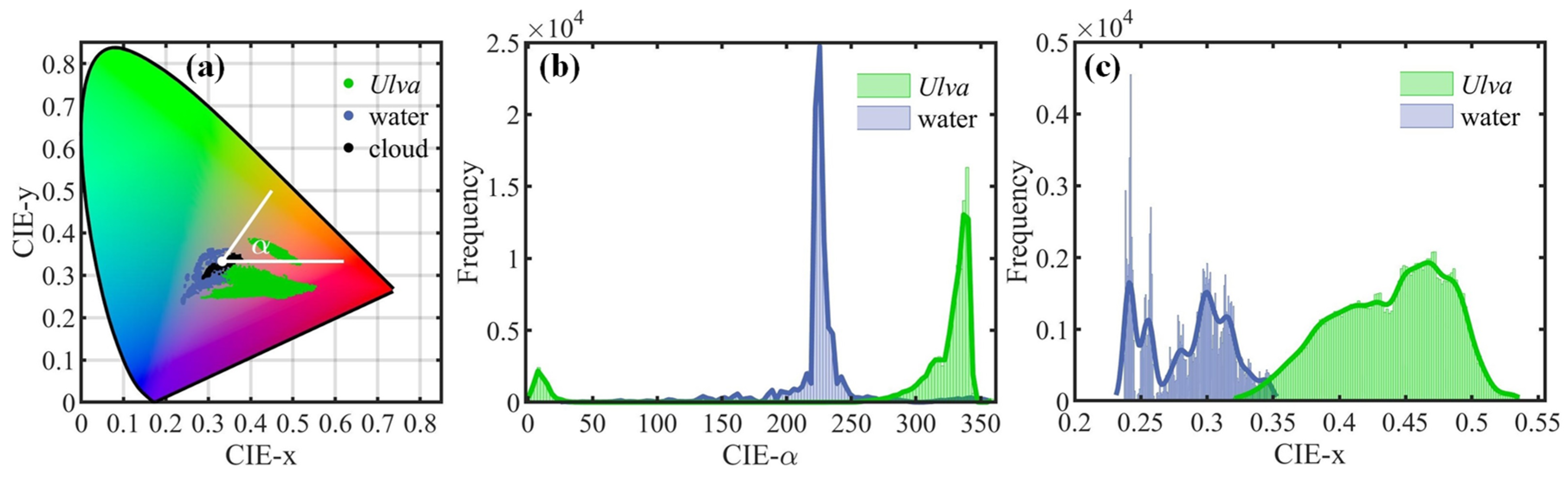
To further ensure the accuracy of Ulva extraction, the above whole-image classification results were bound by the CIE chromaticity information (i.e., hue angle α and CIE-x) from satellite false-color RGB images (termed the CIE-FRGB approach), and the final Ulva detection was then produced. In this approach, satellite RTOA data in three wavebands (NIR, red, and green) were converted into two-dimensional CIE chromaticity space by following Equation (6) [32]. The two-dimensional coordinates CIE-x and CIE-y were obtained following Equation (7), as shown in Figure 4a. Then, in the CIE chromaticity plane (x, y), the hue angle α for any point lies between the vector to the white point (x − 1/3, y − 1/3) and the positive x-axis at y = 1/3, giving higher angles in an anti-clockwise direction [33]. The hue angle α (0–360°) was defined following Equation (8).
Here, satellite RTOA data in NIR, red, and green bands were input to R, G, and B channels, respectively; this was different from previous studies, in which the R, G, and B channels were satellite reflectance values in red, green, and blue bands [4,32,34]. In this study, the RTOA,NIR data were used for the red channel because their values of Ulva pixels significantly increase, which is different to the case of water and other targets. It is easy to understand that the Ulva slicks in satellite FRGB images show the red color gamut and the Ulva-free slicks (mainly including water and clouds) show other colors.
Figure 4 shows the illustration of pixel examples selected from several satellite images, including 117,436 Ulva pixels, 122,000 water pixels, and 88,718 cloud pixels. In practice, for Ulva pixels, the converted colors in the CIE chromaticity diagram were located in the purple–red gamut (see Figure 4a). As shown in Figure 4b, their hue angle CIE-α values were between 0–50° and 250–360°; however, the CIE-α values of the water pixels were mainly between 10 and 250°. Meanwhile, the CIE-x values of Ulva pixels (x > 0.33) were higher than those of most water pixels (x < 0.33), as shown in Figure 4c. Based on the above, this CIE-α and CIE-x information is useful for constraining the detected Ulva pixels that may be misjudged by the TCG index alone. Specifically, if the CIE-FRGB information of a detected Ulva pixel does not satisfy the conditions of (CIE-x > 0.33) and (0° ≤ α ≤ 50° or 250° ≤ α ≤ 360°), it is excluded from the Ulva class.
2.3. Method Assessment
Direct validation of satellite methods is challenging because the field-measured Ulva patches are hardly linked to the satellite-detected patches [35,36]. In this study, the proposed method was tested on several separate groups of representative HY1C/D-CZI images to evaluate the extraction accuracy. The method-detected results were compared with the algae features detected using the TCG index with a visually determined threshold. The corresponding Kappa coefficient, overall accuracy (OA), and F1-score were computed [37]. This accuracy was regarded as self-consistent accuracy because the validation dataset was produced from the manual work from satellite images, but was not obtained from field measurements [38]. Meanwhile, the Ulva pixel area (UA) extracted by different methods was also calculated from the following equation: UA = NA × SR2, where NA is the number of detected Ulva pixels and SR is the spatial resolution of satellite imagery. On the other hand, in order to further validate the method performance, the Ulva results (including spatial distribution and UA) detected by the TCG-LAT method were compared with the Ref-based VBFAH index with a visually determined threshold based on synchronous image pairs.
3. Results
3.1. Necessity of Local Adaptive TCG Threshold to Ulva Detection
Multiple HY1C/D-CZI images over the Yellow Sea during 2020 to 2022 were selected and used to demonstrate the effectiveness of the TCG index in HY1C/D-CZI RTOA images, as shown in Figure 5. It was clearly observed from the bottom panel of Figure 5 that the TCG values of Ulva pixels were higher than those of Ulva-free pixels, and the difference in TCG features remained stable over multiple years, indicating the RTOA-based TCG index was a reliable indicator for satellite extraction of Ulva from HY1C/D-CZI images. Certainly, the TCG index, as a threshold segmentation method, must require a reasonable threshold. Because of complicated observing conditions, the fixed TCG threshold is not suitable for all images, as evidenced by Figure 5 showing the difference in the numeric range of TCG for multiple satellite images.
In addition, we specifically selected one HY1C-CZI image on 23 June 2019 to better illustrate the regional differences in the TCG threshold within the same satellite image, as shown in Figure 6. In this analysis, four sub-regions (termed region 1–4; see their locations in Figure 6a) were chosen to represent different background environments. Their RTOA-based TCG values were obtained as shown in Figure 6b, showing that the Ulva features were effectively extracted by the TCG index from Ulva-free features under different background conditions. Figure 6c shows the scatter distributions of TCG values of all pixels in regions 1–4. It was found that the appropriate TCG thresholds for four local regions were different (see the different-colored lines in Figure 6c representing the respective threshold values for regions 1–4). In this case, the global threshold used for the full image would result in misclassifications or omissions of Ulva detection. Overall, it was evident from the results of Figure 5 and Figure 6 that the TCG thresholds should be determined for different satellite images even for sub-images, suggesting the local adaptive threshold of TCG index is necessary for Ulva detection.
3.2. Ulva Detection and Validation of the TCG-LAT Method
In order to avoid the tedious process of manually selecting a threshold, and to reduce the error caused by the use of a global threshold, this study proposed the TCG-LAT method for automatic Ulva extraction from satellite RTOA images, as mentioned in Section 2.2. Here, the HY1C-CZI image on 6 June 2021, as an illustrative example, was used to demonstrate the performance and accuracy of the proposed TCG-LAT method. As shown in Figure 7a,b, we specifically selected four sub-regions named region 1–4 with different proportions of Ulva features: region 1 without Ulva, region 2 with moderate density of Ulva, region 3 with small plaque Ulva, and region 4 with higher proportions of Ulva. Their distributions of the RTOA-based TCG are mapped in Figure 7c, showing the obvious TCG difference between Ulva pixels and Ulva-free pixels. For four sub-regions, the TH values of the TCG index were automatically defined using the TCG-LAT method (Figure 7e). Then, the corresponding Ulva pixels were automatically extracted following Equation (5), as shown in Figure 7d. By visually comparing Figure 7b,d, the method-detected Ulva features were very consistent with the Ulva features shown in satellite FRGB images.
In addition, Figure 8 shows the application of the TCG-LAT method on the full satellite HY1C-CZI image collected on 6 June 2021. It was clearly observed that the Ulva patches identified by the proposed method correspond well with the patches in satellite FRGB images, and meanwhile no apparent Ulva-free pixels were misclassified to the Ulva class with a low number of false positives. It should be noted that the TCG-LAT method was unable to accurately identify the “other” class, mainly including cloud pixels, sun-glint pixels, and highly turbid waters; fortunately, they did not affect the accuracy of Ulva extraction. The results of Figure 7 and Figure 8 suggest the RTOA-based TCG-LAT method proposed in this study had good performance on the automatic extraction of Ulva blooms.
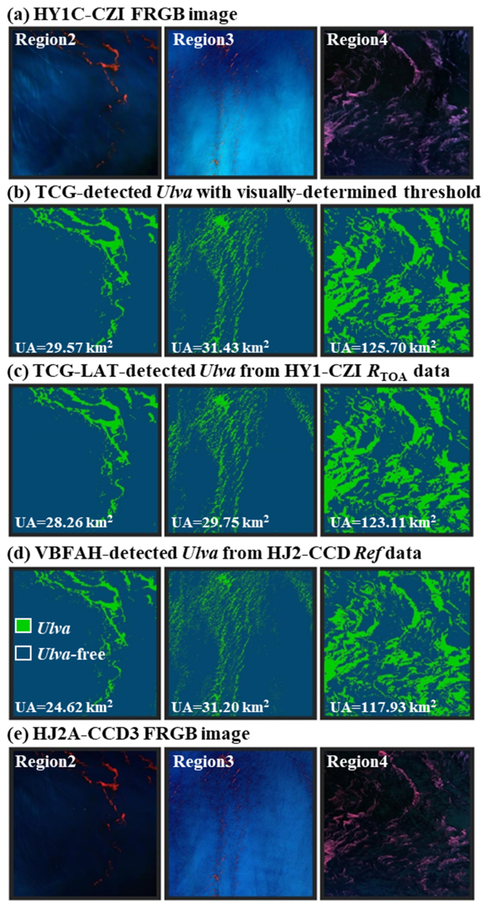
To quantitatively evaluate the detection accuracy of the proposed model, a cross-comparison was conducted between satellite Ulva detection using the proposed TCG-LAT method, the TCG index with a visually determined threshold (TCG-VDT method), and the Ref-based VBFAH index with a visually determined threshold (VBFAH-VDT method). Figure 9 illustrates the cross-comparison between three different methods for three different sub-images (i.e., regions 2–4 in Figure 7). It was evident that the Ulva features detected by the TCG-LAT method (Figure 9c) closely align with the TCG-VDT results (Figure 9b), and closely correspond to the Ulva features depicted in the FRGB image (Figure 9a). Furthermore, the Ulva pixel areas extracted by two methods were comparable (with UA error ≤ 5%), and the TCG-LAT method exhibited high Ulva detection precision, with Kappa value ≥ 97% and F1-score ≥ 98% for the three sub-images. The slightly higher UA error in region 3 of 5% was primarily due to the presence of numerous low-density Ulva patches, making the detected Ulva pixel area somewhat sensitive to changes in the threshold. In addition, we observed that the Ulva features identified using the TCG-LAT method on the HY1C-CZI images (Figure 9c) were in agreement with those detected by the VBFAH-VDT method on the HJ2B-CCD images (Figure 9d). The areas of Ulva algae detected by two methods were similar. While there may be some subjectivity involved in manually selecting the threshold of the TCG and VBFAH indexes, there was a notable level of consistency in the satellite-detected Ulva results using the three methods (see Figure 9), which can effectively demonstrate the reliability of the proposed TCG-LAT method. Thus, the TCG-LAT method showed promise for automated Ulva detection from satellite data.
3.3. Method Performance on Different Observing Conditions
To investigate the method performance on the common and diverse observing conditions (including turbid water, clear water, cloud cover, and sun glint), two satellite images (HY1C-CZI image on 23 June 2021, HY1D-CZI image on 14 June 2023) simultaneously with the above conditions were intentionally used for the case analysis, as shown in Figure 10. Here, for each HY1-CZI image, four sub-images containing Ulva bloom were selected under clear water (R1), turbid water (R2), sun glint (R3), and cloud cover (R4), as shown in middle panel of Figure 10a,b.
For the full satellite images (see left panel of Figure 10a,b), we found from visual inspection that the proposed TCG-LAT method can effectively extract the Ulva features, without obvious misclassification. Specifically, the good performances of the automatic method under different observing conditions were validated by the middle and right panels of Figure 10. Under each condition, the method-detected Ulva features matched well with the visually identified features in satellite RGB images. Meanwhile, the Ulva-free pixels were not misclassified as Ulva, with a low false negative ratio. The results of Figure 10 demonstrate that the automatic TCG-LAT method for Ulva bloom provided satisfactory performances under complex observing conditions, and was less sensitive to the changing environmental background.
3.4. Ulva Blooms in the Yellow Sea in 2023 from HY1C/D-CZI Images
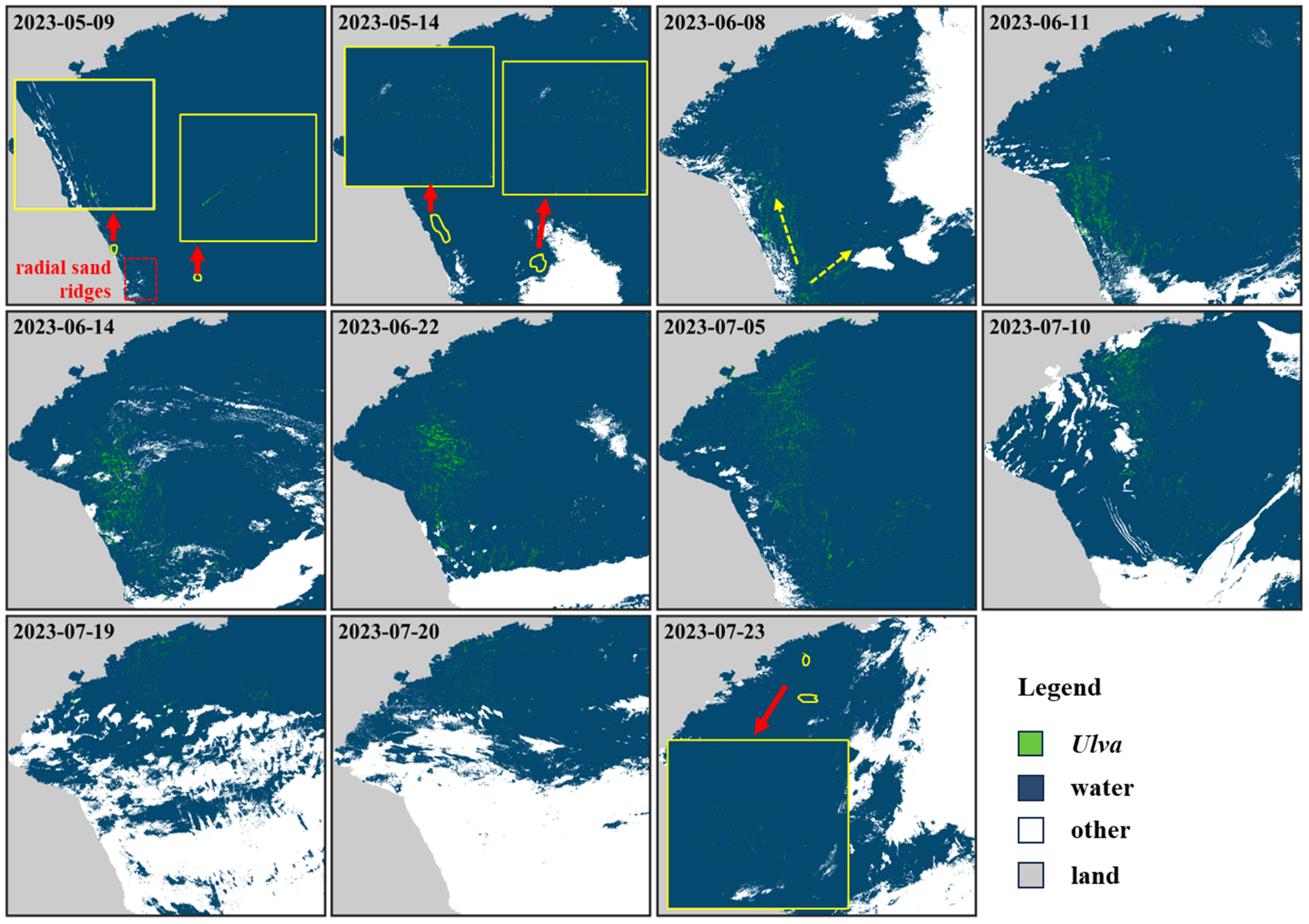
The automatic TCG-LAT method was applied to multi-date HY1C/D-CZI images for monitoring the dynamic process of the 2023 Ulva bloom event in the Yellow Sea, as shown in Figure 11. The proposed TCG-LAT method showed satisfactory performance on different satellite images, which was qualitatively supported by the good consistency with satellite RGB images. Based on the available HY1C/D-CZI images with low cloud cover in the present study, the Ulva outbreak was first observed in the northern and eastern regions of radial sand ridges on 9 May 2023 (see yellow circles in the first subgraph in Figure 11). it is worth noting that it may not be the actual start time of the Ulva outbreak, as early Ulva patches with small-scale features were likely undetected in the 50 m HY1C/D-CZI images by the proposed method. Additionally, the drift trajectory of the Ulva bloom exhibited two directions: one towards the north and the other towards the northeast (see yellow arrows in the third subgraph in Figure 11). According to the available Ulva results detected by the proposed method, the Ulva outbreak reached its peak between 22 June and 5 July 2023. Subsequently, the Ulva bloom started to decline, and by around 23 July 2023, it almost disappeared, with a small amount of Ulva coverage remaining (see yellow circles in the last subgraph in Figure 11). The results of Figure 11 suggested the proposed method can be effectively applied to the long-term remote sensing data, indicating its good stability. With a sufficient number of satellite images, the remote sensing dataset of Ulva distribution can be automatically generated using the TCG-LAT method, thereby providing a valuable database for disaster prevention and the study of spatiotemporal evolution of Ulva blooms.
4. Discussion
An automatic monitoring method for Ulva blooms can improve the efficiency of obtaining Ulva information and is more conducive to the emergency response and disaster management. The TCG index obtained from RTOA data following Equation (4) can efficiently separate the features of algae-free and algae pixels for various optical satellite images with visible and NIR bands [9] and HY1C/D-CZI (Figure 5). The key to the implementation of automatic Ulva detection using the TCG index, as a threshold-based segmentation approach, is the automatic selection of a threshold without operator assistance [39]. The proposed method automatically determined the local adaptive TCG threshold for the moving pixel window, thereby achieving the goal of automatic Ulva extraction from satellite RTOA images (Figure 7), and showed good method performance (see Figure 8 and Figure 9). As shown in the last subfigure of Figure 12, the size change of the moving window (from 100 pixels to 700 pixels) has little effect on the method-detected Ulva results for the test image with 4581 × 5338 pixels. Theoretically increasing the window size can decrease runtime consumption. Thus, the moving window size with 400 × 400 pixels was chosen in this study, and it was not a fixed choice. In order to further ensure the method accuracy, the CIE information (i.e., hue angle α and CIE-x) from satellite false-color RGB images (red channel: NIR band; green channel: red band; blue channel: green band) was used to effectively rule out the confusing Ulva-free targets. Under this optimization, the TCG-LAT method performed well under various observing conditions with cloud cover, sun glint, and turbid water (see Figure 10). Compared to CIE information from true RGB image (red channel: red band; green channel: green band; blue channel: blue band), the CIE-FRGB can better distinguish between Ulva and Ulva-free pixels, especially for CIE-α (Figure 4). This is because the CIE-FRGB approach takes advantage of the marked spectral signature of Ulva, with an obvious RTOA peak in the NIR band [9].
The TCG-LAT method proposed in the present study is easy to implement and its rules are easy to understand. Satellite RTOA data as the input signal, and the TCG index as an indicator for Ulva detection, are easy to obtain following only simple mathematics (i.e., Equations (1) and (4)). Due to the use of satellite RTOA data, the proposed method omitted the atmospheric correction process. Additionally, in terms of data processing, the TCG-LAT method achieves fast and fully automatic monitoring of Ulva blooms, which is highly suitable for a near real-time operational monitoring system. Certainly, the TCG-LAT concept can be applied to satellite Rrc and Rrs data for detecting floating Ulva blooms. For small Ulva patches, the weak Ulva features, especially in coarse-resolution satellite imagery, may be not easy to detect. With the continuous improvement in spatial resolution of satellite imagery, this limitation will be somewhat improved.
In addition, the TCG-LAT method could theoretically be extended to other optical satellite sensors with three visible and NIR wavebands, such as HJ-CCD, GF-WFV, Landsat-OLI, and GOCI. Here, due to space limitations, some selective satellite images of four satellite sensors (including HJ-CCD image on 22 June 2021, GF1-WFV image on 27 June 2023, S2B-MSI on 22 June 2023, and GOCI-II on 5 July 2023) were used to demonstrate the extended application of the TCG-LAT method, as shown in Figure 13. From visual inspection, Ulva extraction from satellite RTOA images of these satellite sensors appeared satisfactory. Therefore, the fully automatic workflow of the TCG-LAT method could also apply to other optical satellite images, and future works can be conducted to verify the method performance. Once confirmed, the Ulva product collection is available based on multi-source satellite imagery, significantly improving the capacity in monitoring and tracking Ulva blooms. Further investigations are needed to quantify the biomass of Ulva blooms and their spatiotemporal variation in the Yellow Sea, and we believe the distribution products of Ulva blooms generated by the TCG-LAT method will provide the basic dataset.
5. Conclusions
A fully automatic and reliable method (termed the TCG-LAT method) was proposed for the rapid detection of Ulva features in satellite imagery. The local adaptive thresholding approach used to select the window-wide TCG threshold and the Ulva optimization of the CIE-FRGB information effectively ensured the success of the TCG-LAT method. This automatic method demonstrated outstanding performance, achieving an overall Ulva detection accuracy exceeding 95% when tested on HY1C/D-CZI data. Moreover, the TCG-LAT method proved to be robust under various observing conditions, including clear water, turbid water, sun glint, and cloud cover, indicating its tolerance to environmental perturbations in satellite imagery. Furthermore, the method revealed successful applicability to other satellite sensors such as HJ-CCD, GF-WFV, Sentinel2-MSI, and GOCI. Future studies should explore its applicability to a wider range of satellite images. The automatic method is expected to be incorporated in the monitoring operational system for rapidly providing Ulva products to the user community once near-real-time satellite images are available.
Author Contributions
Conceptualization, H.Z. and Q.Q.; methodology, H.Z. and D.S.; software, Q.Q. and S.W.; writing—original draft preparation, H.Z.; writing—review and editing, X.Y., S.W. and Z.Z.; funding acquisition, H.Z. and D.S. All authors have read and agreed to the published version of the manuscript.
Funding
This research was funded by National Key Research and Development Program of China (Grant No. 2022YFC3106003), National Natural Science Foundation of China (Grants No. 42106176, 42176179 and 42176181), Natural Science Foundation of Jiangsu Province (Grants No. BK20210667 and BK20211289), Open fund of Key Laboratory of Coastal Zone Exploitation and Protection, Ministry of Natural Resources (Grant No. 2023CZEPK05).
Institutional Review Board Statement
Not applicable.
Informed Consent Statement
Not applicable.
Data Availability Statement
Data are contained within the article.
Acknowledgments
We would like to thank the NSOAS for providing HY1C/D-CZI data, the CRERS for providing HJ-CCD and GF-WFV data, the ESA for Sentinel2-MSI data, the KOSC for GOCI-II data. The findings and opinions contained in this paper are those of the authors and should not be construed as an official policy or decision of the author affiliations.
Conflicts of Interest
The authors declare no conflicts of interest.
References
- Hu, C.; He, M.X. Origin and offshore extent of floating algae in Olympic sailing area. Eos Trans. Am. Geophys. Union 2008, 89, 302–303. [Google Scholar] [CrossRef]
- Qi, L.; Hu, C.; Xing, Q.; Shang, S. Long-term trend of Ulva prolifera blooms in the western Yellow Sea. Harmful Algae 2016, 58, 35–44. [Google Scholar] [CrossRef]
- Hu, L.; Zeng, K.; Hu, C.; He, M.-X. On the remote estimation of Ulva prolifera areal coverage and biomass. Remote Sens. Environ. 2019, 223, 194–207. [Google Scholar] [CrossRef]
- Dai, Y.; Yang, S.; Zhao, D.; Hu, C.; Xu, W.; Anderson, D.M.; Li, Y.; Song, X.P.; Boyce, D.G.; Gibson, L. Coastal phytoplankton blooms expand and intensify in the 21st century. Nature 2023, 615, 280–284. [Google Scholar] [CrossRef]
- Wang, Z.; Xiao, J.; Fan, S.; Li, Y.; Liu, X.; Liu, D. Who made the world’s largest green tide in China?—An integrated study on the initiation and early development of the green tide in Yellow Sea. Limnol. Oceanogr. 2015, 60, 1105–1117. [Google Scholar] [CrossRef]
- Wei, Q.; Wang, B.; Yao, Q.; Fu, M.; Sun, J.; Xu, B.; Yu, Z. Hydro-biogeochemical processes and their implications for Ulva prolifera blooms and expansion in the world’s largest green tide occurrence region (Yellow Sea, China). Sci. Total Environ. 2018, 645, 257–266. [Google Scholar] [CrossRef]
- IOCCG. Observation of Harmful Algal Blooms with Ocean Colour Radiometry; International Ocean Colour Coordinating Group: Dartmouth, NS, Canada, 2021. [Google Scholar]
- Hu, C.; Qi, L.; Hu, L.; Cui, T.; Xing, Q.; He, M.; Wang, N.; Xiao, Y.; Sun, D.; Lu, Y.; et al. Mapping Ulva prolifera green tides from space: A revisit on algorithm design and data products. Int. J. Appl. Earth Obs. 2023, 116, 103173. [Google Scholar] [CrossRef]
- Zhang, H.; Yuan, Y.; Xu, Y.; Shen, X.; Sun, D.; Qiu, Z.; Wang, S.; He, Y. Remote sensing method for detecting green tide using HJ-CCD top-of-atmosphere reflectance. Int. J. Appl. Earth Obs. 2021, 102, 102371. [Google Scholar] [CrossRef]
- Yang, D.; Yuen, K.V.; Gu, X.; Sun, C.; Gao, L. Influences of environmental factors on the dissipation of green tides in the Yellow Sea, China. Mar. Pollut. Bull. 2023, 189, 114737. [Google Scholar] [CrossRef]
- Cao, M.; Li, X.; Cui, T.; Pan, X.; Li, Y.; Chen, Y.; Wang, N.; Xiao, Y.; Song, X.; Xu, Y.; et al. Unprecedent green macroalgae bloom: Mechanism and implication to disaster prediction and prevention. Int. J. Digit. Earth 2023, 16, 3772–3793. [Google Scholar] [CrossRef]
- Xiao, Y.; Liu, R.; Kim, K.; Zhang, J.; Cui, T. A Random Forest-Based Algorithm to Distinguish Ulva prolifera and Sargassum from Multispectral Satellite Images. IEEE Trans. Geosci. Remote Sens. 2021, 60, 4201515. [Google Scholar] [CrossRef]
- Wan, X.; Wan, J.; Xu, M.; Liu, S.; Zhang, X. Enteromorpha coverage information extraction by 1D-CNN and Bi-LSTM networks considering sample balance from GOCI images. IEEE J. S. Top. Appl. 2021, 14, 9306–9317. [Google Scholar] [CrossRef]
- Qiu, Z.; Li, Z.; Bilal, M.; Wang, S.; Sun, D.; Chen, Y. Automatic method to monitor floating macroalgae blooms based on multilayer perceptron: Case study of Yellow Sea using GOCI images. Opt. Express 2018, 26, 26810–26829. [Google Scholar] [CrossRef] [PubMed]
- Guo, Y.; Gao, L.; Li, X. A Deep Learning Model for Green Algae Detection on SAR Images. IEEE Trans. Geosci. Remote Sens. 2022, 60, 4210914. [Google Scholar] [CrossRef]
- Keesing, J.K.; Liu, D.; Fearns, P.; Garcia, R. Inter-and intra-annual patterns of Ulva prolifera green tides in the Yellow Sea during 2007–2009, their origin and relationship to the expansion of coastal seaweed aquaculture in China. Mar. Pollut. Bull. 2011, 62, 1169–1182. [Google Scholar] [CrossRef] [PubMed]
- Xiao, Y.; Zhang, J.; Cui, T.; Gong, J.; Liu, R.; Chen, X.; Liang, X. Remote sensing estimation of the biomass of floating Ulva prolifera and analysis of the main factors driving the interannual variability of the biomass in the Yellow Sea. Mar. Pollut. Bull. 2019, 140, 330–340. [Google Scholar] [CrossRef]
- Hu, C. A novel ocean color index to detect floating algae in the global oceans. Remote Sens. Environ. 2009, 113, 2118–2129. [Google Scholar] [CrossRef]
- Qi, L.; Wang, M.; Hu, C.; Holt, B. On the capacity of Sentinel-1 synthetic aperture radar in detecting floating macroalgae and other floating matters. Remote Sens. Environ. 2022, 280, 113188. [Google Scholar] [CrossRef]
- Xing, Q.; Hu, C. Mapping macroalgal blooms in the Yellow Sea and East China Sea using HJ-1 and Landsat data: Application of a virtual baseline reflectance height technique. Remote Sens. Environ. 2016, 178, 113–126. [Google Scholar] [CrossRef]
- Shi, W.; Wang, M. Green macroalgae blooms in the Yellow Sea during the spring and summer of 2008. J. Geophys. Res. 2009, 114, C12010. [Google Scholar] [CrossRef]
- Muzhoffar, D.A.F.; Sakuno, Y.; Taniguchi, N.; Hamada, K.; Shimabukuro, H.; Hori, M. Automatic Detection of Floating Macroalgae via Adaptive Thresholding Using Sentinel-2 Satellite Data with 10 m Spatial Resolution. Remote Sens. 2023, 15, 2039. [Google Scholar] [CrossRef]
- Garcia, R.A.; Fearns, P.; Keesing, J.K.; Liu, D. Quantification of floating macroalgae blooms using the scaled algae index. J. Geophys. Res. Ocean. 2013, 118, 26–42. [Google Scholar] [CrossRef]
- Estévez, J.; Salinero-Delgado, M.; Berger, K.; Pipia, L.; Rivera-Caicedo, J.P.; Wocher, M.; Reyes-Muñoz, P.; Tagliabue, G.; Boschetti, M.; Verrelst, J. Gaussian processes retrieval of crop traits in Google Earth Engine based on Sentinel-2 top-of-atmosphere data. Remote Sens. Environ. 2022, 273, 112958. [Google Scholar] [CrossRef] [PubMed]
- Shi, H.; Xiao, Z.; Liang, S.; Zhang, X. Consistent estimation of multiple parameters from MODIS top of atmosphere reflectance data using a coupled soil-canopy-atmosphere radiative transfer model. Remote Sens. Environ. 2016, 184, 40–57. [Google Scholar] [CrossRef]
- Wang, W.; Ma, Y.; Meng, X.; Sun, L.; Jia, C.; Jin, S.; Li, H. Retrieval of the Leaf Area Index from MODIS Top-of-Atmosphere Reflectance Data Using a Neural Network Supported by Simulation Data. Remote Sens. 2022, 14, 2456. [Google Scholar] [CrossRef]
- Wolanin, A.; Rozanov, V.V.; Dinter, T.; Noël, S.; Vountas, M.; Burrows, J.P.; Bracher, A. Global retrieval of marine and terrestrial chlorophyll fluorescence at its red peak using hyperspectral top of atmosphere radiance measurements: Feasibility study and first results. Remote Sens. Environ. 2015, 166, 243–261. [Google Scholar] [CrossRef]
- Zhang, H.; Qiu, Z.; Devred, E.; Sun, D.; Wang, S.; He, Y.; Yu, Y. A simple and effective method for monitoring floating green macroalgae blooms: A case study in the Yellow Sea. Opt. Express 2019, 27, 4528–4548. [Google Scholar] [CrossRef] [PubMed]
- Qiu, S.; He, B.; Zhu, Z.; Liao, Z.; Quan, X. Improving Fmask cloud and cloud shadow detection in mountainous area for Landsats 4–8 images. Remote Sens. Environ. 2017, 199, 107–119. [Google Scholar] [CrossRef]
- Wang, M.; Hu, C. Automatic Extraction of Sargassum Features from Sentinel-2 MSI Images. IEEE Trans. Geosci. Remote Sens. 2021, 59, 2579–2597. [Google Scholar] [CrossRef]
- Wang, M.; Shi, W. Cloud masking for ocean color data processing in the coastal regions. IEEE Trans. Geosci. Remote Sens. 2006, 44, 3105–3196. [Google Scholar] [CrossRef]
- Hou, X.; Feng, L.; Dai, Y.; Hu, C.; Gibson, L.; Tang, J.; Lee, Z.; Wang, Y.; Cai, X.; Liu, J.; et al. Global mapping reveals increase in lacustrine algal blooms over the past decade. Nat. Geosci. 2022, 15, 130–134. [Google Scholar] [CrossRef]
- Hendrik, W.; Marcel, W. True Colour Classification of Natural Waters with Medium-Spectral Resolution Satellites: SeaWiFS, MODIS, MERIS and OLCI. Sensors 2015, 15, 25663–25680. [Google Scholar] [CrossRef] [PubMed]
- Wang, S.; Li, J.; Zhang, W.; Cao, C.; Zhang, B. A dataset of remote-sensed Forel-Ule Index for global inland waters during 2000–2018. Sci. Data 2021, 8, 26. [Google Scholar] [CrossRef] [PubMed]
- Hu, C.; Hardy, R.; Ruder, E.; Geggel, A.; Feng, L.; Powers, S.; Hernandez, F.; Graettinger, G.; Bodnar, J.; McDonald, T. Sargassum coverage in the northeastern Gulf of Mexico during 2010 from Landsat and airborne observations: Implications for the Deepwater Horizon oil spill impact assessment. Mar. Pollut. Bull. 2016, 107, 15–21. [Google Scholar] [CrossRef] [PubMed]
- Zhang, H.; Liu, J.; Ye, X.; Bai, Y.; Sun, D.; Wang, S.; Dong, J. Detecting Sargassum bloom directly from satellite top-of-atmosphere reflectance with high-resolution images. IEEE Trans. Geosci. Remote Sens. 2023, 61, 4206212. [Google Scholar] [CrossRef]
- Powers, D. Evaluation: From Precision, Recall and F-Factor to ROC, Informedness, Markedness & Correlation. J. Mach. Learn. Res. 2011, 2, 37–63. [Google Scholar]
- Wang, M.; Hu, C. Satellite remote sensing of pelagic Sargassum macroalgae: The power of high resolution and deep learning. Remote Sens. Environ. 2021, 264, 112631. [Google Scholar] [CrossRef]
- Otsu, N. A Threshold Selection Method from Gray-Level Histograms. IEEE Trans. Syst. Man Cybern. 2007, 9, 62–66. [Google Scholar] [CrossRef]
Figure 1.
Workflow for the automatic Ulva detection from optical satellite images.

Figure 2.
HY1C-CZI false-color RGB image on 13 June 2023 (a), and the distribution of RTOA,red (b). The bright targets (i.e., other class) were extracted using the BT_red approach (c). The diagram for the automatic Thred selection (d).
Figure 2.
HY1C-CZI false-color RGB image on 13 June 2023 (a), and the distribution of RTOA,red (b). The bright targets (i.e., other class) were extracted using the BT_red approach (c). The diagram for the automatic Thred selection (d).

Figure 3.
The diagrams for the frequency distribution histogram of TCG: without Ulva (a) and with Ulva pixels (b); the corresponding example of satellite images (c,d).
Figure 3.
The diagrams for the frequency distribution histogram of TCG: without Ulva (a) and with Ulva pixels (b); the corresponding example of satellite images (c,d).

Figure 4.
The distribution of the Ulva and Ulva-free pixel samples in the CIE color space (a). Histograms of CIE-α (b) and CIE-x (c) for the Ulva and water pixels.
Figure 4.
The distribution of the Ulva and Ulva-free pixel samples in the CIE color space (a). Histograms of CIE-α (b) and CIE-x (c) for the Ulva and water pixels.

Figure 5.
Satellite images of HY1C/D-CZI during 2020 to 2022 (top panel). The FRGB (NIR–red–green) images of the selected sub-images (middle panel), where their locations marked by white boxes were shown in top panel, and their TCG distributions (bottom panel).
Figure 5.
Satellite images of HY1C/D-CZI during 2020 to 2022 (top panel). The FRGB (NIR–red–green) images of the selected sub-images (middle panel), where their locations marked by white boxes were shown in top panel, and their TCG distributions (bottom panel).

Figure 6.
Satellite HY1C-CZI image collected on 23 June 2023 showing Ulva bloom in the Yellow Sea (a). The TCG images for the selected sub-regions (b), where their locations marked by white boxes are shown in (a), and the pixel-wise distribution of TCG for four regions (c) with individual regional thresholds marked by blue dashed lines.

Figure 7.
The HY1C-CZI FRGB image on 6 June 2021 and the locations of the selected sub-regions marked by white boxes (a). For four sub-regions, the FRGB images (b), TCG images (c), Ulva detection results (d), and the TH thresholds determined by the TCG-LAT method (e).
Figure 7.
The HY1C-CZI FRGB image on 6 June 2021 and the locations of the selected sub-regions marked by white boxes (a). For four sub-regions, the FRGB images (b), TCG images (c), Ulva detection results (d), and the TH thresholds determined by the TCG-LAT method (e).

Figure 8.
The HY1C-CZI FRGB image on 6 June 2021 (a) and the detected Ulva result using the TCG-LAT method (b).
Figure 8.
The HY1C-CZI FRGB image on 6 June 2021 (a) and the detected Ulva result using the TCG-LAT method (b).

Figure 9.
Cross-comparison between satellite Ulva detection using different three methods for three selected sub-regions as depicted in Figure 7. HY1C-CZI FRGB images (a) and the Ulva results detected by the TCG-VDT method (b) and TCG-LAT method (c). HJ2B-CCD FRGB images (e) and the Ulva results detected by the VBFAH-VDT method (d).

Figure 10.
The performance analysis of the TCG-LAT method under different observing conditions based on HY1C-CZI image (a) and HY1D-CZI image (b): clear water (R1), turbid water (R2), sun glint (R3), and cloud cover (R4).
Figure 10.
The performance analysis of the TCG-LAT method under different observing conditions based on HY1C-CZI image (a) and HY1D-CZI image (b): clear water (R1), turbid water (R2), sun glint (R3), and cloud cover (R4).

Figure 11.
Ulva distribution and coverage area for the 2023 Ulva bloom event detected from HY1C/D-CZI images.
Figure 11.
Ulva distribution and coverage area for the 2023 Ulva bloom event detected from HY1C/D-CZI images.

Figure 12.
The Ulva results detected by the TCG-LAT method and their runtimes with different window sizes.
Figure 12.
The Ulva results detected by the TCG-LAT method and their runtimes with different window sizes.

Figure 13.
Satellite FRGB images and the Ulva detection results using the TCG-LAT method from HJ-CCD image (a-1,a-2), GF1-WFV image (b-1,b-2), Sentinel2B-MSI (c-1,c-2), and GOCI (d-1,d-2).
Figure 13.
Satellite FRGB images and the Ulva detection results using the TCG-LAT method from HJ-CCD image (a-1,a-2), GF1-WFV image (b-1,b-2), Sentinel2B-MSI (c-1,c-2), and GOCI (d-1,d-2).


Table 1.
The wavelength settings and spatial resolution of the satellite sensors.
| Waveband | Wavelength/μm (Bands) | ||||
|---|---|---|---|---|---|
| HY1C/D-CZI | GF1-WFV | HJ1A/B-CCD | Sentinel2-MSI | GOCI-II | |
| Blue | 0.42–0.50 (B1) | 0.45–0.52 (B1) | 0.43–0.52 (B1) | 0.458–0.523 (B2) | 0.443 (B3) |
| Green | 0.52–0.60 (B2) | 0.52–0.59 (B2) | 0.52–0.60 (B2) | 0.543–0.578 (B3) | 0.555 (B6) |
| Red | 0.61–0.69 (B3) | 0.63–0.69 (B3) | 0.63–0.69 (B3) | 0.65–0.68 (B4) | 0.68 (B9) |
| NIR | 0.76–0.89 (B4) | 0.77–0.89 (B4) | 0.76–0.90 (B4) | 0.785–0.90 (B8) | 0.865 (B12) |
| Spatial resolution | 50 m | 16 m | 30 m | 10 m | 250 m |
Disclaimer/Publisher’s Note: The statements, opinions and data contained in all publications are solely those of the individual author(s) and contributor(s) and not of MDPI and/or the editor(s). MDPI and/or the editor(s) disclaim responsibility for any injury to people or property resulting from any ideas, methods, instructions or products referred to in the content. |
© 2024 by the authors. Licensee MDPI, Basel, Switzerland. This article is an open access article distributed under the terms and conditions of the Creative Commons Attribution (CC BY) license (https://creativecommons.org/licenses/by/4.0/).
Share and Cite
MDPI and ACS Style
Zhang, H.; Qin, Q.; Sun, D.; Ye, X.; Wang, S.; Zong, Z. Automatic Detection of Floating Ulva prolifera Bloom from Optical Satellite Imagery. J. Mar. Sci. Eng. 2024, 12, 680. https://doi.org/10.3390/jmse12040680
AMA Style
Zhang H, Qin Q, Sun D, Ye X, Wang S, Zong Z. Automatic Detection of Floating Ulva prolifera Bloom from Optical Satellite Imagery. Journal of Marine Science and Engineering. 2024; 12(4):680. https://doi.org/10.3390/jmse12040680
Chicago/Turabian StyleZhang, Hailong, Quan Qin, Deyong Sun, Xiaomin Ye, Shengqiang Wang, and Zhixin Zong. 2024. "Automatic Detection of Floating Ulva prolifera Bloom from Optical Satellite Imagery" Journal of Marine Science and Engineering 12, no. 4: 680. https://doi.org/10.3390/jmse12040680
Note that from the first issue of 2016, this journal uses article numbers instead of page numbers. See further details here.