
Grid-Impedance-Based Transient Current Control for Offshore Wind Turbines under Low-Voltage Fault

School of Electrical Engineering, Southeast University, Nanjing 210096, China
*
Author to whom correspondence should be addressed.
J. Mar. Sci. Eng. 2024, 12(5), 691; https://doi.org/10.3390/jmse12050691
Submission received: 14 March 2024
/
Revised: 20 April 2024
/
Accepted: 20 April 2024
/
Published: 23 April 2024
(This article belongs to the Special Issue Advances in Offshore Wind—2nd Edition)
Abstract
:In order to enhance the transient stability of offshore wind turbines (OWTs) in marine energy systems, the grid codes stipulate that OWTs should possess the low-voltage ride-through (LVRT) ability of being grid-tied and injecting reactive current during grid fault. However, the grid-side converter (GSC) of OWTs may lose stability under weak grid or severe fault conditions due to inaccurate current references. To address this issue, a novel transient current control method is proposed to improve the transient stability of permanent-magnet-synchronous-generator (PMSG)-based OWTs. The feature of DC-link overvoltage is investigated and is alleviated by utilizing the GSC’s overcurrent capacity and chopper. Additionally, the equivalent circuit of the PMSG-based OWT connected to the onshore grid is derived based on Thevenin’s theorem. The feasible current region (FCR) is then determined, taking into account the GSC capacity, pre-fault power ability, LVRT requirement, and synchronization stability. Furthermore, a grid-impedance-based transient current control method is designed to enhance the fault ride-through performance and mitigate power oscillation of the OWT under various transient grid impedance and fault conditions. Finally, a simulation model is conducted using PSCAD v4.6.3 software to validate the effectiveness of the proposed method.
1. Introduction
To address the environmental pollution and fossil fuel crisis, there has been a significant development in renewable energy over the past decade, which is expected to play a crucial role in the future energy system [1,2]. Among renewable energy sources, wind power accounts for 23% of the total global renewable energy, ranking second after hydrogen power [3]. Offshore wind power, as a form of marine renewable energy, has gained considerable attention due to its abundance of wind resources, proximity to load centers, and minimal land occupation [4,5]. Extensive research has been conducted on the transmission schemes for offshore wind turbines, including high-voltage alternative current (HVAC) and high-voltage direct current (HVDC) [6]. HVDC is more economically and operationally efficient when the transmission distance exceeds 50 km. However, HVAC is widely used for offshore power transmission as most offshore wind farms are located within 50 km of the onshore grid. In terms of generator types, offshore wind turbines are typically equipped with either doubly fed induction generators (DFIGs) or permanent magnet synchronous generators (PMSGs), both of which are connected to the grid through power electronic devices [7]. PMSGs are gaining popularity in the marine sector due to their advantages of not requiring a gearbox, higher power scalability, and greater flexibility in supporting the grid [8]. In this study, we focus on PMSG-based offshore wind turbines as the research objective.
The PMSG-based offshore wind turbine (OWT) is connected to the power grid through a power electronic device (PED) called the fully rated converter [9]. As the penetration rate of offshore wind power increases, the power grid structure undergoes significant changes, with a shift towards the use of massive PEDs instead of synchronous generators (SGs). However, PEDs have poorer overcurrent and overvoltage capabilities compared to traditional SGs, leading to notable frequency and voltage instability. Additionally, the overhead line in the onshore grid is prone to grounding faults, which can result in DC-link overvoltage and off-grid accidents for offshore wind turbines, as the onshore grid voltage decreases [9]. This further exacerbates the issues of active power reduction and onshore grid voltage fluctuation. To mitigate these challenges, many countries have implemented grid codes that mandate wind turbines to possess low-voltage ride-through (LVRT) abilities. These abilities enable OWTs to keep grid-tied and provide reactive current to the onshore grid during faults [10,11,12].
There are three main LVRT methods for offshore wind turbines (OWTs): software modified method, hardware modified method, and a combination of software and hardware approaches [13]. The software modified method can be further classified into modified converter control [14,15], improved pitch angle control [16], and algorithm-based control [17,18]. On the other hand, the hardware modified method involves the addition of external devices, such as a chopper circuit [19,20], flexible AC transmission system (FACTs) devices [21,22], and energy storage systems [23]. Furthermore, researchers have also explored the combination of software and hardware approaches [24,25]. The grid-side converter (GSC) plays a crucial role in determining the grid-tied characteristics of PMSG-based OWTs. The output power can be controlled by adjusting the current reference of the GSC, as the active and reactive currents are directly proportional to the active and reactive power, respectively. Under low-voltage fault conditions, the GSC switches to the reactive current injection priority mode instead of the active current injection priority mode used in steady-state operation [26]. However, the active current and reactive current are limited by the capacity of the GSC. Consequently, in severe fault scenarios, the OWT may experience a significant reduction in active current or active power, leading to electricity waste and frequency fluctuations. To mitigate the reduction in active current during grid faults, researchers have depicted the feasible power region of the converter for better power allocation [27,28]. Additionally, proper current references are provided to the GSC’s controller based on the feasible current region, taking into account the converter capacity and grid code requirements [29].
In the previously mentioned studies, the LVRT strategy is primarily developed for the strong power grids, where the power system has a robust ability to withstand voltage dips. However, due to factors such as long-distance transmission lines and high levels of renewable energy integration, the onshore grid may exhibit weaker characteristics, including low inertia, high impedance, unstable voltage, and limited resistance to interference. As a result, greater demands are being placed on the LVRT technology of OWTs. When operating in a weak grid with high impedance or during severe low-voltage faults, the OWT is prone to losing synchronization with the onshore grid due to improper current references to converters, resulting in transient current and power oscillations [30]. In order to address this issue, a current reference control scheme that considers grid impedance and a feasible current region during faults has been proposed based on the analysis of stable equilibrium points [31]. Additionally, pre-fault power ability is also an important factor affecting the feasible current region. Therefore, it is valuable to design an accurate feasible current region to better allocate the current references of GSC during low-voltage faults.
To address the aforementioned issue, this paper proposes a grid-impedance-based transient current control method to mitigate DC-link overvoltage and support system stability with different grid strengths. The key contributions of this paper are summarized as follows:
- (1)
- This paper explores the DC-link overvoltage trajectory with different grid voltage dip conditions and proposes a solution by utilizing GSC’s short-time overcurrent capacity and chopper.
- (2)
- To provide accurate guidance for transient current control, the feasible current region is proposed through visualization of GSC capacity, pre-fault power ability, LVRT requirement and synchronization stability.
- (3)
- A grid-impedance-based transient current control is utilized to enhance the LVRT performance of OWTs and mitigate power oscillations under different voltage dip and grid impedance conditions.
The remainder of this paper is organized as follows. Section 2 presents the detailed model of PMSG-based OWTs and analyzes the feature of DC-link overvoltage. Section 3 establishes the feasible current region considering the four aforementioned constraints. Section 4 describes the grid-impedance-based transient current control strategy for GSC during fault periods. Section 5 presents case studies to validate the proposed method. Finally, the conclusions are presented in Section 6.
2. Problem Description and Analysis
2.1. System Description
As depicted in Figure 1, power grids integrated with offshore wind farms are composed of offshore wind turbines, submarine cables, transformers, transmission lines, and onshore grids. Offshore wind farms are usually composed of 30–50 OWTs, and the OWTs are collected by several submarine cables to offshore stations. The transformer in offshore station can improve the voltage from 35 kV to 220 kV, and then the electricity is transmitted from the offshore station to the onshore grid through the transmission line. For convenience, a single-machine equivalent model is used to study the transient characteristics of offshore wind farms. A PMSG-based OWT is also depicted in Figure 1, which contains a turbine, generator, chopper, DC-link capacitor, machine-side converter (MSC), and GSC. MSC can convert alternative current to direct current, and GSC is used to convert direct current to alternative current. The chopper circuit is composed of a power electronic switch and resistor Rch, which can absorb surplus power under low-voltage fault. Pitch angle control, MSC control, GSC control, and chopper control jointly form the control system of the OWT.
In the event of a symmetrical low-voltage fault in the onshore grid, both the voltage of the onshore grid and the OWT are influenced. The active current may decrease, and the DC-link voltage (Udc) exceeds the withstand value of converter, which is harmful to the device and further increases the risk of off-grid accidents in the OWT.
2.2. LVRT Requirement and Control Method
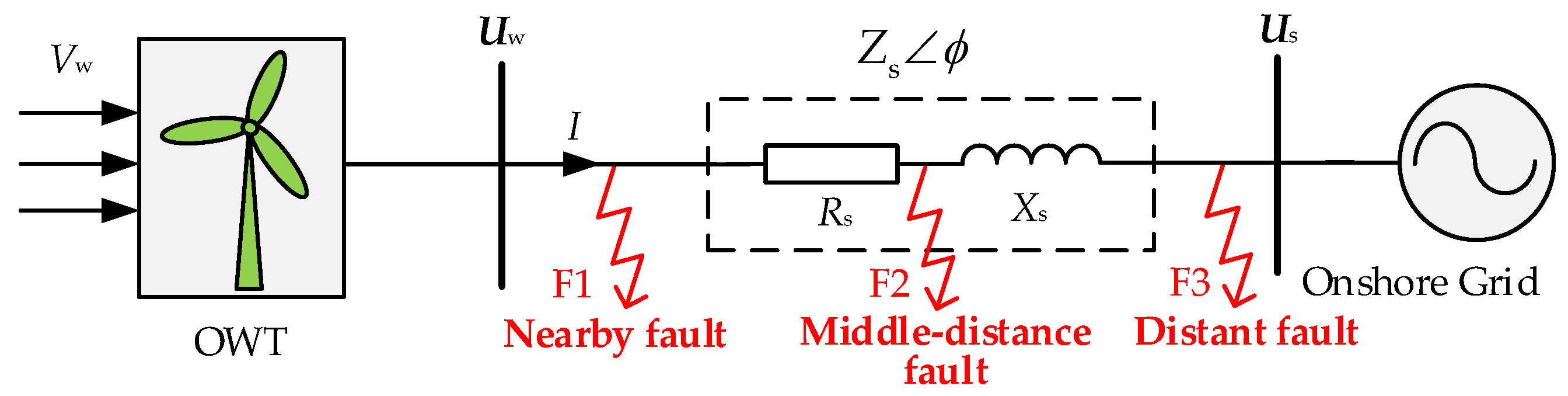
If the onshore grid suffers from low-voltage fault, the point of integration (POI) voltage drops with the reduction of onshore grid voltage vector (Us). According to the fault position in the simplified topology of Figure 2, the low-voltage fault can be divided into three types, namely nearby fault, middle-distance fault, and distant fault. In Figure 2, Vw is the wind velocity, Uw is the POI voltage vector, and Zs is the grid impedance vector of onshore grid. Rs and Xs are the resistance and reactance of onshore grid, respectively, and Zs = Zs∠ϕ = Rs + jXs. Zs and ϕ are the amplitude and phase angle of Zs.
When the low-voltage fault occurs in the power grid, the wind turbine may be disconnected from the grid, causing negative impacts to the voltage and frequency stability. To mitigate the negative influences, grid codes in most countries require the wind turbine to have the LVRT ability that the wind turbine is grid-tied and provide reactive current to the power grid for voltage support. According to China grid code [32], the required LVRT curve for wind turbine is shown in Figure 3. When faults or disturbances cause the voltage sag at POI connected to the OWT, the wind turbine should be gird-tied and provide reactive current if the grid voltage is between 0.2 and 0.9 p.u. And wind turbine is allowed to be off-grid while the grid voltage drops under 0.2 p.u. shown in the pink zone of Figure 3. The blue line is the reactive current curve according to grid code requirement.
The LVRT methods of onshore wind turbines are also used in OWTs [33]. The voltage dip amplitude of POI depends on the fault type. According to the grid code, when three-phase fault occurs, the OWT should have the ability of dynamic reactive power support, which requires the OWT to produce dynamic reactive current as follows:
where Iqref is the reference of reactive current Iq; Iq0 is the initial value of reactive current, of which the value is 0. IqN is the rated value of reactive current; and Kq is the reactive current coefficient, ranging from 1.5 to 3. Uw is the POI voltage, namely the amplitude of Uw.
If the OWT is in LVRT state, the GSC controller adopts reactive priority mode, and the active current reference can be calculated as
where Idmax is the maximum value of active current Id and Im is the maximum current of GSC.
As the initial part of OWTs, GSC determines the grid-tied characteristics of OWTs. The conventional LVRT control structure of GSC is shown in Figure 4. GSC adopts the voltage-oriented-vector-based control method, and the voltage vector is oriented towards the d-axis as follows:
where Uwd is the d-axis component of Uw and Uwq is the q-axis componet of Uw.
The angle δ is obtained via phase-locked loop (PLL) and is oriented with the d-axis voltage of the onshore grid. The active and reactive power of GSC are
When the OWT is in steady state, the dq-axis voltage is calculated according to the dq-axis coordinate system:
To avoid the influence of coupling voltage, the feed-forward decoupling control is introduced. Adopting PI controller in the current inner loop and ignoring Rs, the closed-loop control expressions are as follows:
where Gi(s) is the transfer function of PI controller; Uid and Uiq are the d-axis component and q-axis component of GSC voltage; Lf is the filter inductance; and ωw is the angular frequency of the POI voltage.
In Figure 4, GSC adopts a double closed-loop control method, containing an out-loop module and a current inner-loop control module. The out-loop module aims to maintain the DC-link voltage or reactive power at a target value and sends current reference to the inner-loop control module. The DC-link voltage is controlled by active current, and reactive power is controlled by reactive current. Based on the state flag, the GSC controller can switch between active current priority mode and reactive current priority mode. When the OWT is in steady state (state 1), GSC operates in active current priority mode with reactive current maintained at zero. While in LVRT state (state 2), GSC adopts reactive current priority mode to produce active current to support onshore grid voltage.
2.3. DC-Link Overvoltage during Fault
As is stated above, two initial factors affecting the operation security of OWTs are DC-link voltage and GSC current during low-voltage state. When onshore grid voltage drops deeply, the DC-link overvoltage occurs because of the unbalanced power between MSC and GSC. Thereby, the chopper circuit is activated to absorb the unbalanced power for the suppression of DC-link overvoltage via resistance energy consumption.
Figure 5 reveals the transient power flow of the OWT during low-voltage fault. Wind power is transmitted from MSC to GSC. According to the power balance law, the DC-link power is calculated according to
where PMSC and PGSC are the active power of MSC and GSC, respectively. PChop is the absorbed power of chopper. Chopper circuit is disconnected during steady state and put into operation during low-voltage fault.
The instantaneous power on the DC-link side of GSC is UdcIdc. Ignoring the transformer and line losses, UdcIdc = 1.5UwId is met in Figure 5. The DC-link voltage Udc is directly proportional to the active current Id, so Udc can be controlled through Id. According to the outer-loop control module of DC-link voltage, the active current reference in steady state is
where Kup and Kui are the proportional and integral coefficients of PI controller, respectively; Udcref is the reference value of the DC-link voltage.
Considering that the response speed of the current inner-loop control is relatively fast, the active current Id strictly follows its reference value. Therefore, ignoring the dynamic process of the current inner-loop control, the active current can be directly replaced by its reference value. Neglecting the power loss, the power balance equation of GSC can be expressed as
As shown in Figure 5, the grid voltage decreases when a symmetrical fault occurs. When the voltage drops under 0.9 p.u., the OWT operates in the reactive current priority mode. And the OWT may lower its active current for more reactive current requirement from onshore grid. Thereby, the DC-link voltage increases according to (10), which may trigger the action of DC protection when the DC-link voltage exceeds the maximum value of Udcm. The trajectory of the non-chopper method is O-A-B-G, as shown in Figure 6. With the utilization of the chopper, the chopper is put into operation when the DC-link voltage exceeds Uchop, and the maximum voltage is Udc1. By adopting the chopper and the short-time overcurrent capacity of GSC, the DC-link voltage can be alleviated without raising the DC protection with maximum value of Udc2, which is lower than Udc1. The DC-link voltage trajectory is adjusted from line O-A-C-D-E to line O-F-G-H-E.
In Figure 6, set voltage dip conditions: Uw0 ≥ Uw1 ≥ Uw2 ≥ Uw3. According to the Equation (9), the greater the voltage drops, the larger the unbalanced power, raising more apparent overcurrent features. So, an OWT under the grid voltage condition of Uw1 easily reaches the chopper action voltage (Uchop), and the transient DC-link voltage is highest in the four conditions. The DC-link voltage comparison results are Udc0 ≤ Udc1 ≤ Udc2 ≤ Udc3. We can also draw a conclusion that the DC-link voltage rise time is smaller than the DC voltage recovery time, which is apparent in Figure 6. By adopting GSC’s short-term overcurrent capacity, the DC-link overvoltage can be significantly suppressed; meanwhile, the usage frequency and operation time of the chopper are reduced.
3. Feasible Current Region of GSC
To better depict the feasible current region, we introduce four constraints, i.e., GSC capacity, pre-fault power ability, LVRT requirement, and synchronization stability.
- (1)
- Constraint 1: GSC capacity.
Id and Iq are controlled in the LVRT controller by using the PI controllers. Id and Iq are limited by the GSC capacity as follows:
- (2)
- Constraint 2: pre-fault power ability.
The active power is determined by wind speed, and we assume that the pre-fault power ability is P0. Since the low-voltage transient process belongs to the millisecond level, the wind speed fluctuation can be ignored. When the onshore grid voltage drops from normal value (Uw0) to lower value, the active power of GSC may decrease. To keep the DC-link voltage stable according to (9), the active current is improved to a certain extent as follows, so the transient active current satisfies
where a is the voltage drop degree, and id0 is the pre-fault active current.
- (3)
- Constraint 3: LVRT requirement.
When the onshore grid voltage drops in the interval of [0.2 p.u., 0.9 p.u.], the OWT employs the LVRT mode of reactive current priority. The reactive current reference is given according to (1):
- (4)
- Constraint 4: synchronization stability.
Maintaining synchronization with onshore grid is essential for OWTs during low-voltage fault. Affected by long-distance transmission lines and high penetration of power electronic devices, the onshore grid tends to be weak in keeping voltage and frequency stable. Inexact current values of GSC can arise from the loss of synchronization in a weak grid or severe fault condition. According to the voltage stability analysis results of POI, the voltage fluctuation during LVRT period is affected by transient current of the OWT’s GSC. Ensuring onshore grid voltage stability is the premise of allocating current distribution and supporting reactive power. Therefore, synchronization constraint should be fully considered in feasible current region depiction.
Based on Figure 2, we further establish the simplified circuit shown in Figure 7a when low-voltage fault occurs. According to the fault position in the onshore grid, we set Zs1 as the impedance vector from OWT to fault point. Zs1 is zero when nearby fault occurs. Zs2 is the impedance vector from onshore grid to fault point, and Zsf is the fault impedance vector. Zs2 is zero when distant fault occurs. Iw is the injection current vector from OWT to fault point and Is is the injection current vector from onshore grid to fault point. If is the grounding-fault current vector.
For the simplified circuit in Figure 7a, it can be equivalent to a simpler circuit with a voltage source and a resistor connected in series shown in Figure 7b by using the Thevenin’s theorem. In the Figure 7b, the equivalent grid voltage vector Ueq and equivalent grid impedance vector Zeq are affected by fault position, onshore grid voltage, and onshore grid impedance. Req and Xeq are the equivalent grid resistance and equivalent grid reactance of Zeq, respectively. We can calculate Ueq and Zeq according to
The relationship between Id, Iq, and AC voltage can be expressed as follows:
The voltage feature is depicted in Figure 8. The x–y coordinate system is a synchronous rotational, and x-axis is oriented to Ueq. For simplification, Iw is controlled in the d–q coordinate system. δ is the phase of PLL’s d-axis leading Ueq and ϕ is the power factor angle.
Based on (5), there exists an inequality constraint of residual grid voltage, current references, and grid impedance, which is the precondition of the existence of PLL’s equilibrium point [31] as represented by (16):
where Ueq is the equivalent grid impedance, namely the amplitude of Ueq.
Since −1 ≤ sinδ ≤ 1, (17) can be further derived into [34]:
Given equivalent grid voltage and grid impedance, the transient current regions are obtained based on (11) and (17). Then, considering that reactive current injection takes priority, and the remaining capacity is utilized for active current, the relationships can be depicted in three situations in Figure 9. When constraint 1 and constraint 4 are separated or tangent, the current region of GSC is only determined by constraint 1. While constraint 1 and constraint 4 are intersected, the current region of GSC is limited by the two constraints.
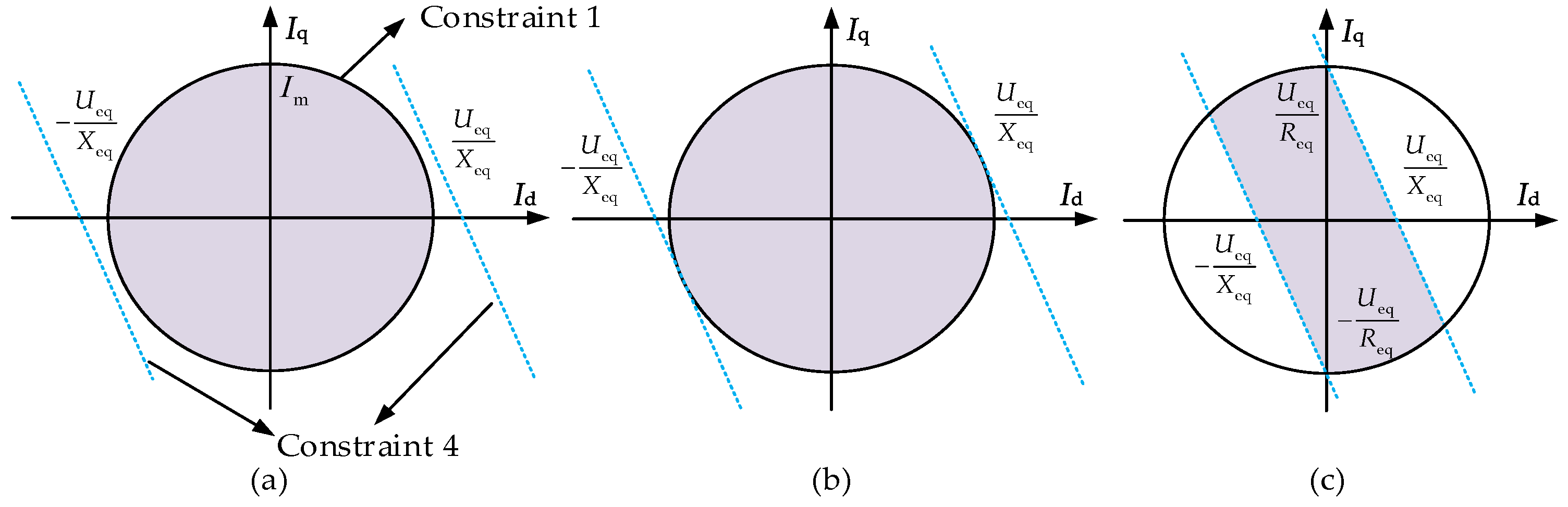
To better depict the current region of GSC, we set the condition that Id is non-negative and Iq is non-positive during LVRT state:
And we can further depict the current region in Figure 10, containing three situations: (a) Ueq ≥ Xeq·Im; the absolute value of Id and Iq both can reach Im. (b) Req·Im ≤ Ueq ≤ Xeq·Im; only the absolute value of Iq both can reach Im. (c) Ueq ≤ Req·Im; the absolute value of Id and Iq all less than Im. For situation (c), if we set Iq equals Im, there is no stable equilibrium point in this region, which may cause a loss of synchronization problem.
As a result, we can finally obtain the feasible current region combining the four constraints. For steady state, the FCR is affected by GSC capacity, pre-fault power ability, and synchronization stability in Figure 11a, while for transient state, the FCR is affected by GSC capacity, pre-fault power ability, LVRT requirement, and synchronization stability in Figure 11b. Moreover, the current region can be enlarged by adopting the short-time overcurrent capacity of GSC. To avoid the OWT being off-grid or losing synchronization stability during low-voltage fault, it is necessary to ensure that the transient current references are in reasonable region. The proper current references can be given according to the designed FCR considering grid synchronization stability and grid code requirement.
4. Grid-Impedance-Based Transient Current Control
Based on the feasible current region, we set three situations for calculation the current references. The calculation method requires pre-fault parameters, including pre-fault power ability, equivalent grid impedance, equivalent grid voltage, and so on. The grid-impedance-based current calculation equations are determined as follows:
- (1)
- Situation (a): Ueq ≥ Xeq·Im
According to (1), the reactive current reference Iqref is
Basically, the active current reference Idref can be obtained:
- (2)
- Situation (b): Req·Im ≤ Ueq ≤ Xeq·Im
The reactive current calculation refers to (19). According to (11) and (17), the transient active current reference can be derived as follows:
- (3)
- Situation (c): Ueq ≤ Req·Im
Substituting (1) and (20) into (6), the transient reactive current reference is
And the active current calculation refers to (21). To make the active current smoother and reduce the usage frequency of chopper, the short-term overcurrent capacity of GSC is adopted for current region expansion. We draw the Id-Uw curve under situation (a) in Figure 12. We define the critical voltage as the maximum voltage at which the reactive current meets the LVRT requirement without sacrificing the active current. Substituting (1) and (12) into (11), the critical voltage U2 can be given by the following equation:
As depicted in Figure 12, the active current Id varies with the OWT voltage. When the OWT voltage is within [U2, 1.0], Id increases as the voltage decreases and reaches the maximum value of Im when the voltage drops to U2. During the voltage of [0.2, U2], Id decreases as the voltage drops. And Id is zero when voltage is below 0.2 since the OWT is off-grid according to the grid code. Under situation (a), Id can be obtained according to the red line in Figure 12. So, U2 is the action voltage of chopper. If the POI voltage is less than U2, the chopper is put into operation for DC protection.
By establishing the equivalent circuit of faulty onshore grid integrated with the OWT and current calculation method based on feasible current region, we design the transient current control method depicted in Figure 13. Zeq and Ueq are obtained by utilizing the grid impedance identification module and equivalent impedance calculation module. The obtained parameters are then sent to GSC controller to further calculate the desired active current reference and reactive current reference. Similar to the conventional LVRT method in Figure 4, the GSC control signal is generated through the inner-loop controller and pulse width modulation (PWM). Subsequently, by employing the proposed control method, the proper current references are provided, and DC-link overvoltage and synchronization instability are alleviated.
For the OWT’s off-grid state verification, we set two judge conditions. One is the amplitude of voltage Uw. Another is the fault duration tf. If the voltage drops under 0.2 p.u., the OWT is allowed to be off-grid. According to Figure 3, we can obtain the maximum tolerant time tfw of different transient voltage:
The flowchart of the step-by-step process of proposed transient current control method is depicted in Figure 14. It can be seen that there are several steps:
- (1)
- Identifying onshore grid fault and collecting fault parameters, i.e., faulty point, faulty degree, onshore gird impedance, voltage, active/reactive current of the OWT.
- (2)
- Judging the operation status of the OWT according to Uw. If 0.9 ≤ Uw ≤ 1.0, the OWT adopts steady control mode of active current priority. If 0.2 ≤ Uw ≤ 0.9, the OWT adopts LVRT control mode of reactive current priority. Otherwise, the OWT is off-grid due to the deep voltage drop.
- (3)
- Calculating the equivalent grid impedance and equivalent grid voltage Ueq.
- (4)
- Calculating active current and reactive current of GSC according to the three situations in Figure 10.
- (5)
- Sending control signals to GSC. As indicated, by employing the proposed method during low-voltage fault, the proper current reference is obtained to support onshore grid voltage and ensure synchronization stability.
5. Simulation Results
5.1. System Parameters
To verify the correctness of the proposed control method, the simulation model is carried out with a 5 MW PMSG-based OWT in PSCAD environment. The schematic structure and detailed parameters are presented in Figure 2 and Table 1. A short-circuit ratio (SCR) is adopted to describe the grid strength [35], and onshore grid with a low SCR presents higher grid impedance, deeper voltage drops and slower voltage recovery compared to onshore grid with larger SCR.
5.2. Case 1: Strong Grid (SCR = 10), P0 = 1 p.u., Uw = 0.8 p.u.
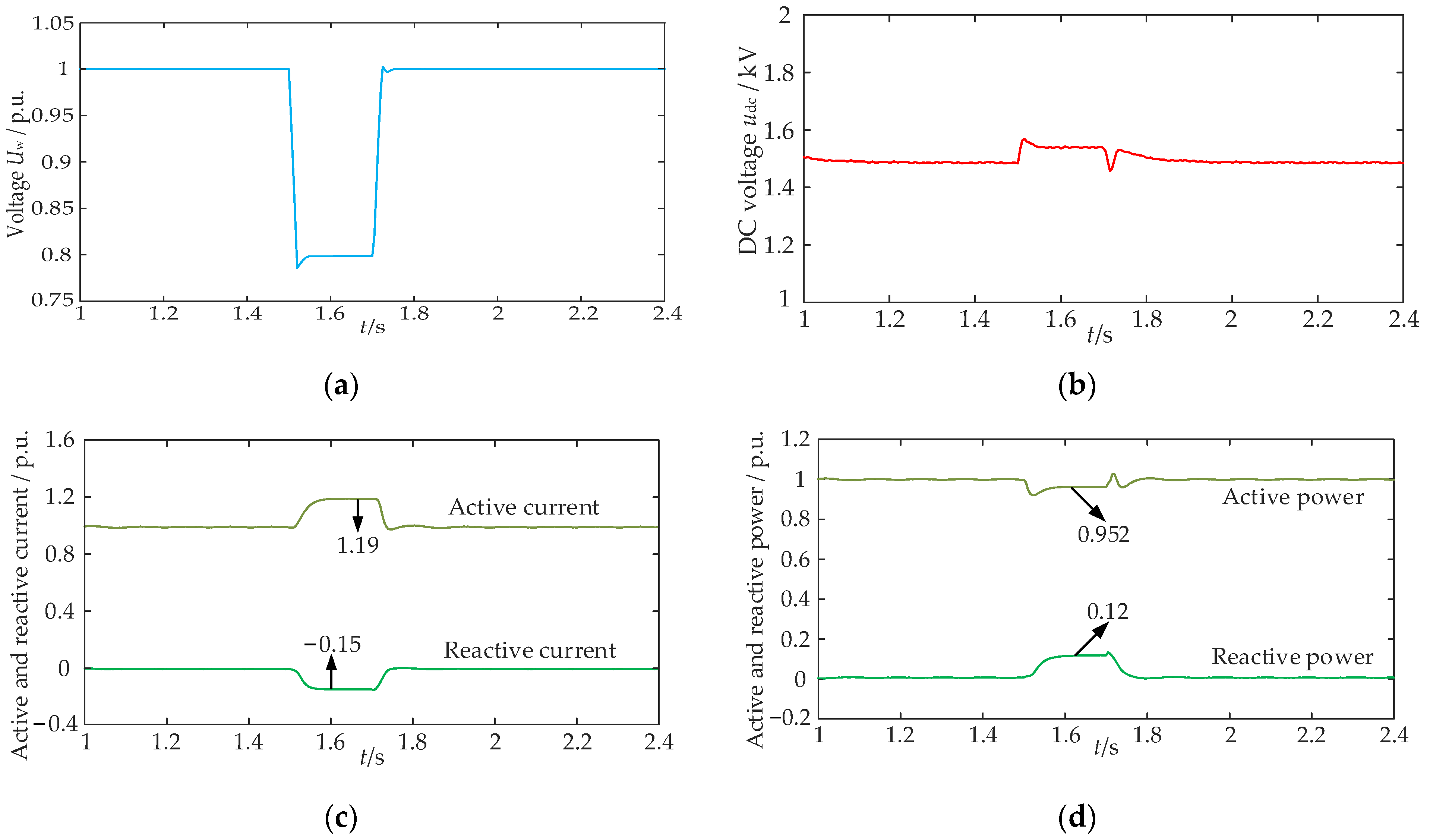
The simulated results are shown in Figure 15. In this simulation, a three-phase fault occurs at 1.5 s, bringing slight decline of the POI voltage from 1 p.u. to 0.8 p.u in Figure 15a. From Figure 15b, the DC-link voltage of the OWT increases to 1.58 kV, which is far lower than its protection value of 1.95 kV (1.3 p.u.). According to the grid-impedance-based current calculation equations of proposed method, the OWT operates in situation (a) as it satisfies Ueq ≥ Xeq·Im. And the transient currents in Figure 15c are calculated as Iq = −0.15 p.u., Id = 1.19 p.u. During the transient state, the active current is determined by GSC capacity. Affected by the voltage sag, active power drops from 1 p.u. to 0.952 p.u., and reactive power rises from 0 p.u. to 0.12 p.u. After the fault is cleared, the OWT can recover to the steady state.
5.3. Case 2: Strong Grid (SCR = 10), P0 = 1 p.u., Uw = 0.4 p.u.
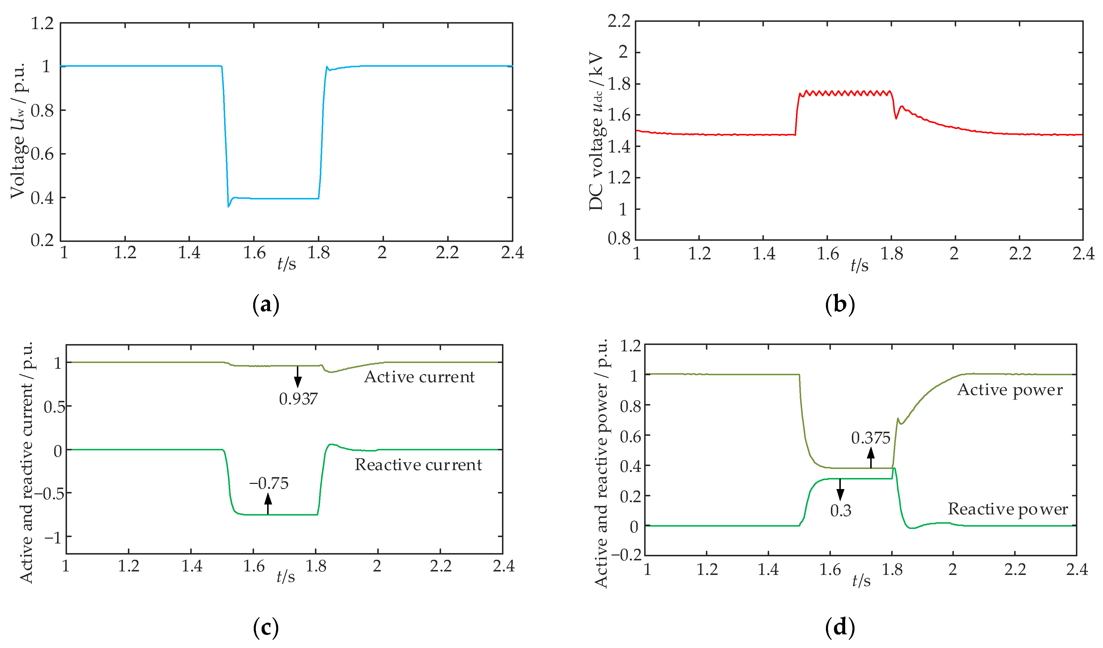
Figure 16 shows the simulation wave forms of the PMSG-based OWT during the POI voltage at 0.4 p.u. For the condition of deep onshore voltage dips, the DC-link voltage is 1.76 kV, increasing the voltage to 1.17 times in Figure 16b, and the chopper is adopted to alleviate the overvoltage. The OWT operates in situation (a), which is consistent with the stability analysis process in Figure 15. From Figure 16c, active current and reactive current are 0.937 p.u. and −0.75 p.u., respectively. Furthermore, we can obtain the active power of 0.375 p.u. and reactive current of 0.3 p.u. in Figure 16d. Combined with Figure 15, reactive current and DC-link voltage of the OWT both rise with the decline of POI voltage. The more voltage drops, the more severe the DC-link voltage is. The simulation results verify the correctness of the analysis in Section 2 and Section 3.
5.4. Case 3: Strong Grid (SCR = 5), P0 = 0.5 p.u., Uw = 0.7 p.u.
Similarly, the influence of pre-fault power ability on system stability is investigated. Figure 17 depicts the simulation results of the OWT during POI voltage at 0.7 p.u. According to Figure 17b, the DC-link voltage varies slightly as GSC can produce more active current to compensate for the power drop issue caused by voltage drop. Active current is initially set as 0.5 p.u. and rises to 0.714 p.u. during fault. Reactive current varies from 0 to −0.3 p.u., as shown in Figure 17c according to the grid-impedance-based current calculation equations. Thus, the active power remains at a steady value of 0.5 p.u. and reactive power improves to 0.21 p.u. For the non-rated power situation, the OWT can provide reactive current support for onshore gird while producing more active current to suppress the DC-link overvoltage issue during the low-voltage fault.
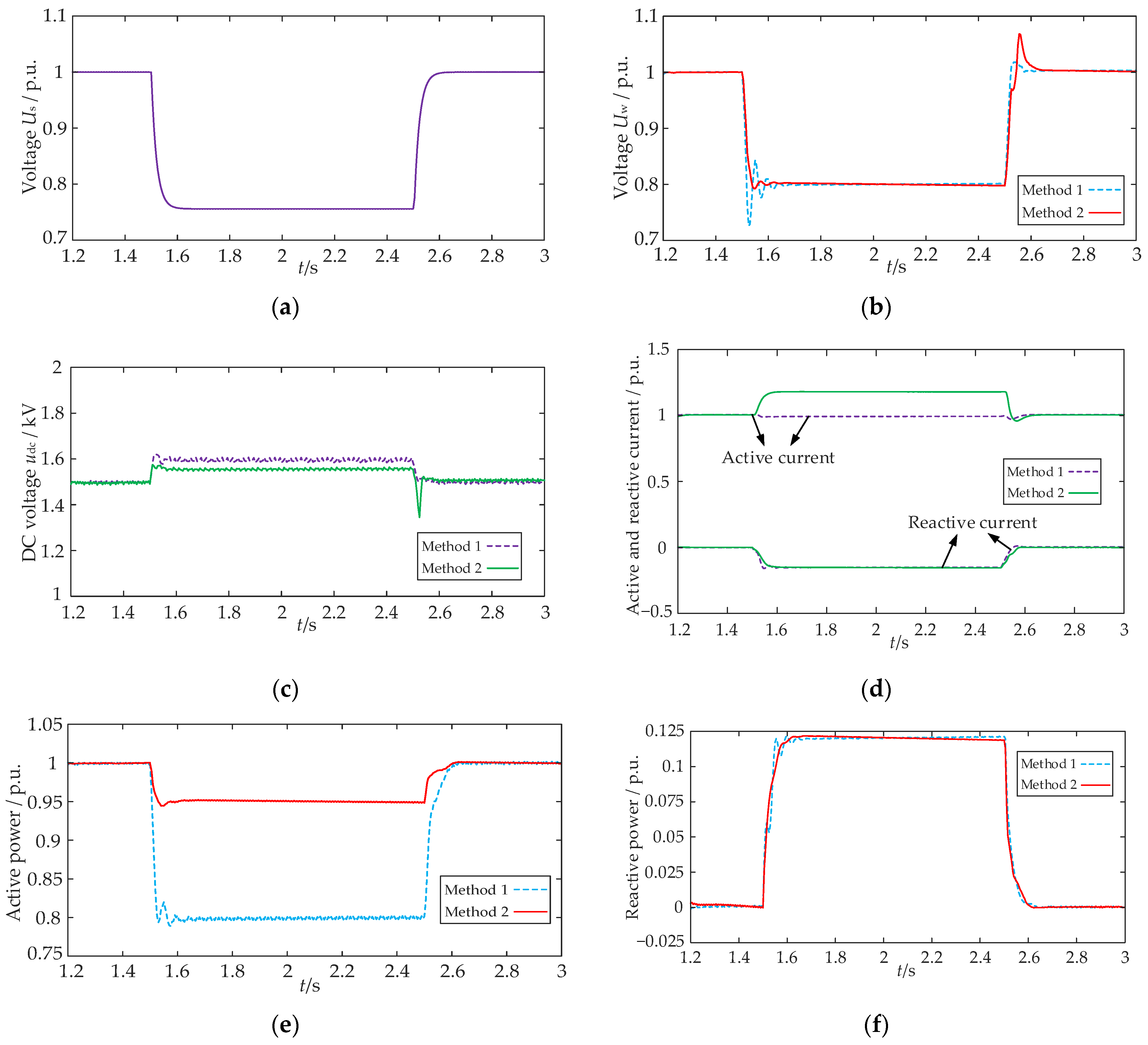
5.5. Case 4: Weak Grid (SCR = 1.5), P0 = 1 p.u., Uw = 0.8 p.u.
Case 4 is to verify the method under weak grid with slight voltage sag. According to Figure 18a, the onshore gird voltage drops to 0.756 p.u. and the POI voltage drops to 0.8 p.u., both in Method 1 and Method 2. In Figure 18c, the DC-link voltages of two methods are 1.62 p.u. and 1.55 p.u., respectively. So, the OWT with Method 1 needs to withstand more severe overvoltage. With Method 1, the active current and reactive current are 0.989 p.u. and −0.15 p.u., respectively. In Method 2, the OWT operates in situation (a). The active current is 1.19 p.u., which is larger than the value of Method 1 in Figure 18d. Furthermore, the active power of Method 1 is 0.79 p.u., which is lower than the active power of 0.95 p.u. in Method 2. The value of reactive current is same with that of Method 1, so the reactive power is 0.12 p.u. both in Method 1 and Method 2. Compared to Method 1, OWTs adopting Method 2 can produce more active power for the onshore grid in the transient period.
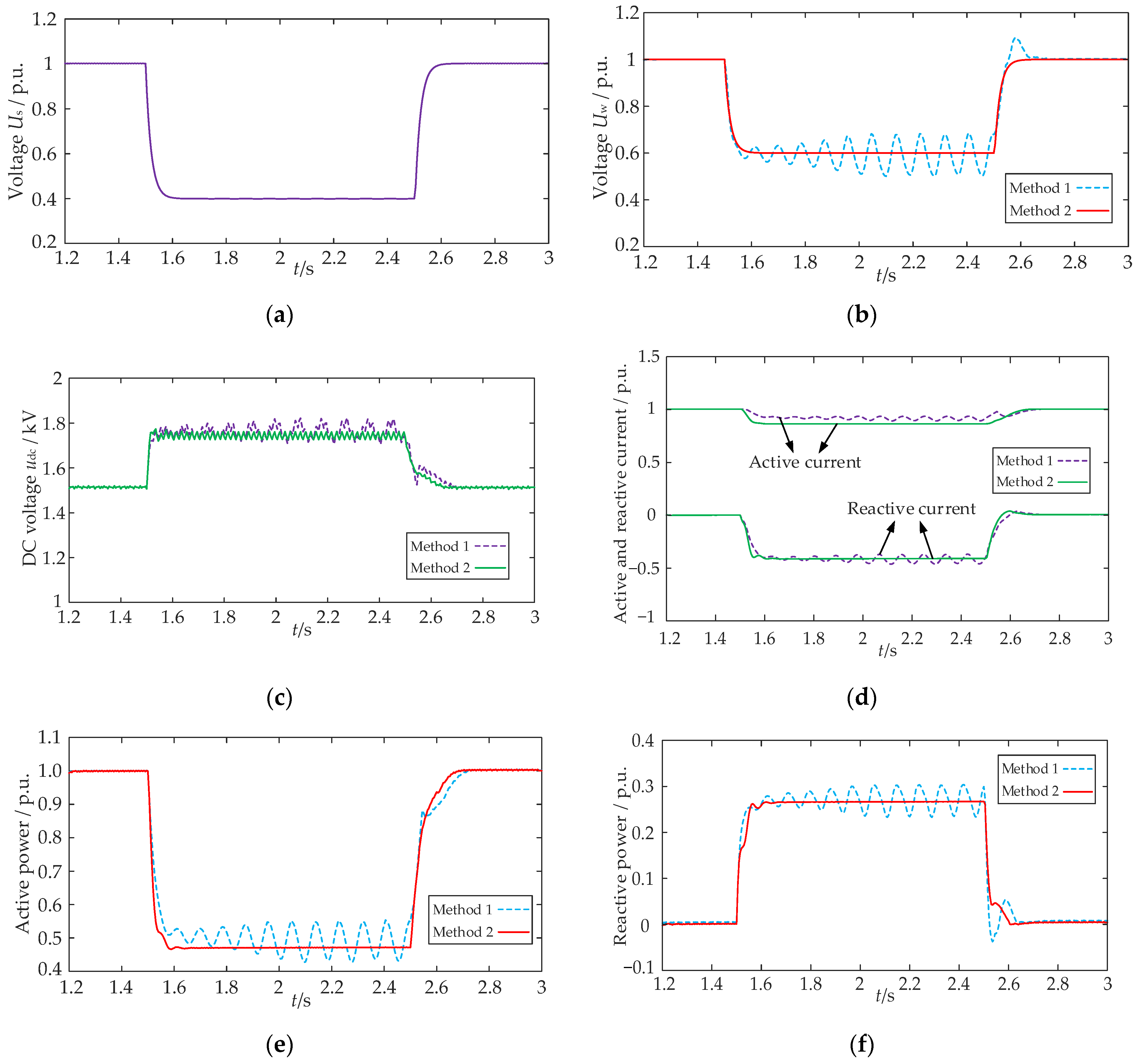
5.6. Case 5: Weak Grid (SCR = 1.5), P0 = 1 p.u., Uw = 0.6 p.u.
The simulation is carried out in the condition of SCR = 1.5 and deep voltage dip of onshore grid shown in Figure 19. The system response with Method 1 and Method 2 are compared in Figure 19b–f, respectively. According to (24), when the POI voltage drops to 0.6 p.u., the maximum tolerant time is 1.41 s, which is longer than the simulation fault time of 1 s. Obvious oscillations get to occur in the DC-link voltage, transient current, and transient power, implying that the system loses its stability with Method 1. So, Method 1 is not suitable for OWTs in weak grids with deep voltage drop. From Figure 19b, the POI voltage drops to 0.6 p.u., and it is calculated that Req·Im ≤ Ueq ≤ Xeq·Im according to the grid-impedance-based current calculation equations. So, the OWT is in the region of situation (b) with Method 2. The active current and reactive current are 0.783 p.u. and −0.45 p.u., respectively, while in Method 1, the active value of 0.89 exceeds the feasible transient region, which causes system instability. The maximum value of active power and reactive power are 0.47 p.u. and 0.27 p.u. during the steady state of LVRT, respectively. By calculating the transient grid impedance, the proper current references are given to GSC controller, avoiding OWT instability during weak grid with low-voltage fault. Thus, compared to the conventional method, the DC-link overvoltage and power oscillations are suppressed significantly by adopting the proposed transient current control method.
6. Conclusions
In this paper, we propose a novel transient current control method for offshore wind turbines that takes into account the grid-impedance-based feasible current region to enhance the system’s transient stability. Several important findings can be summarized as follows:
- (1)
- The proposed solution combining GSC’s short-time overcurrent capacity and chopper can mitigate the DC-link overvoltage arising from unbalanced power during low-voltage fault.
- (2)
- The feasible current region considering GSC current ability, pre-fault power ability, LVRT requirement, and synchronization stability is further explored to provide accurate guidance for transient current control, which presents visual characterization of transient current references more reasonably.
- (3)
- The proposed method suppresses power oscillations and ensures voltage stability more effectively compared to the traditional LVRT method. Extensive simulations have confirmed its excellent performance in transient stability under different voltage dip or grid impedance conditions, without requiring additional hardware investment.
Moreover, it should be noted that the transient stability of a single OWT is not solely determined by the feasible current region, but also by the interactive behavior of other OWTs in the farm. Future research will focus on fault detection and decentralized autonomous control of OWTs.
Author Contributions
Conceptualization, Z.Y. and B.G.; methodology, Z.Y. and Z.C.; validation, J.F.; software, Z.C.; investigation, Z.Y. and J.F.; original draft, Z.Y. and B.G.; writing—review and editing, Z.Y., B.G. and Z.C. All authors have read and agreed to the published version of the manuscript.
Funding
This research was supported by Science and Technology Project of State Grid Corporation of China (5108-202218280A-2-69-XG).
Institutional Review Board Statement
Not applicable.
Informed Consent Statement
Not applicable.
Data Availability Statement
Data are contained within the article.
Conflicts of Interest
The authors declare no conflicts of interest.
References
- Zhao, Y.; Zhang, G.; Hu, W.; Huang, Q.; Chen, Z.; Blaabjerg, F. Meta-learning based voltage control for renewable energy integrated active distribution network against topology change. IEEE Trans. Power Syst. 2023, 38, 5937–5940. [Google Scholar] [CrossRef]
- Li, J.; Wu, J.; Wang, H.; Zhang, Q.; Zheng, H.; Song, Y. Sequential model predictive control for grid connection in offshore wind farms based on active disturbance rejection. J. Mar. Sci. Eng. 2024, 12, 21. [Google Scholar] [CrossRef]
- The International Renewable Energy Agency (IRENA). Renewable Energy Statistics 2023. Available online: https://www.irena.org/Publications/2023/Jul/Renewable-energy-statistics-2023 (accessed on 6 July 2023).
- Song, D.; Shen, G.; Huang, C.; Huang, Q.; Yang, J.; Dong, M.; Joo, Y.; Duić, N. Review on the application of artificial intelligence methods in the control and design of offshore wind power systems. J. Mar. Sci. Eng. 2024, 12, 424. [Google Scholar] [CrossRef]
- Guo, Y.; Wang, H.; Lian, J. Review of integrated installation technologies for offshore wind turbines: Current progress and future development trends. Energy Convers. Manag. 2022, 255, 115319. [Google Scholar] [CrossRef]
- Deng, J.; Cheng, F.; Yao, L.; Xu, J.; Mao, B.; Li, X.; Chen, R. A review of system topologies, key operation and control technologies for offshore wind power transmission based on HVDC. IET Gener. Transm. Distrib. 2023, 17, 3345–3363. [Google Scholar] [CrossRef]
- Jia, K.; Yang, Z.; Zheng, L.; Zhu, Z.; Bi, T. Spearman correlation-based pilot protection for transmission line connected to PMSGs and DFIGs. IEEE Trans. Ind. Inform. 2021, 17, 4532–4544. [Google Scholar] [CrossRef]
- Xue, T.; Lyu, J.; Wang, H.; Cai, X. A complete impedance model of a PMSG-based wind energy conversion system and its effect on the stability analysis of MMC-HVDC connected offshore wind farms. IEEE Trans. Energy Convers. 2021, 36, 3449–3461. [Google Scholar] [CrossRef]
- Li, B.; Zheng, D.; Li, B.; Jiao, X.; Hong, Q.; Ji, L. Analysis of low voltage ride-through capability and optimal control strategy of doubly-fed wind farms under symmetrical fault. Prot. Control Mod. Power Syst. 2023, 8, 36. [Google Scholar] [CrossRef]
- Li, W.; Zhu, M.; Chao, P.; Liang, X.; Xu, D. Enhanced FRT and postfault recovery control for MMC-HVDC connected offshore wind farms. IEEE Trans. Power Syst. 2020, 35, 1606–1617. [Google Scholar] [CrossRef]
- Wei, J.; Cao, Y.; Wu, Q.; Li, C.; Huang, S.; Zhou, B.; Xu, D. Coordinated droop control and adaptive model predictive control for enhancing HVRT and post-event recovery of large-scale wind farm. IEEE Trans. Sustain. Energy 2021, 12, 1549–1560. [Google Scholar] [CrossRef]
- Zhang, J.; Sun, H.; Li, W.; Jia, Y.; Han, Z.; Tao, X. A FRCC method based on rapid voltage response for LVRT recovery of D-PMSG. Energy Sources Part A Recovery Util. Environ. Eff. 2019, 45, 8320–8336. [Google Scholar] [CrossRef]
- Saidi, Y.; Mezouar, A.; Benmahdjoub, M.; Brahmi, B.; Meddah, A.; Khalfallah, B.; Kerrouche, K. A comprehensive review of LVRT capability and advanced nonlinear backstepping control of grid-connected wind-turbine-driven permanent magnet synchronous generator during voltage dips. J. Control Autom. Electr. Syst. 2022, 33, 1773–1791. [Google Scholar] [CrossRef]
- Guan, L.; Yao, J. Dynamic stability improvement scheme for dual-sequence PLLs in VSC based renewable energy generation system during asymmetrical LVRT. Int. J. Power Energy Syst. 2023, 145, 108683. [Google Scholar] [CrossRef]
- Gajewski, P.; Pieńkowski, K. Control of wind turbine system with PMSG for low voltage ride through. In Proceedings of the International Symposium on Electrical Machines (SME), Andrychow, Poland, 10–13 June 2018; pp. 1–5. [Google Scholar]
- Thet, A.; Saitoh, H. Pitch control based on voltage dip detection for improving the LVRT of wind farm. IEEJ Trans. Electr. Electron. Eng. 2012, 7, 136–143. [Google Scholar] [CrossRef]
- Magesh, T.; Devi, G.; Lakshmanan, T. Improving the performance of grid connected wind generator with a PI control scheme based on the metaheuristic golden eagle optimization algorithm. Electr. Power Syst. Res. 2023, 214, 108944. [Google Scholar] [CrossRef]
- Uddin, M.; Arifin, M.; Rezaei, N. A novel neuro-fuzzy based direct power control of a DFIG based wind farm incorporated with distance protection scheme and LVRT capability. IEEE Trans. Ind. Appl. 2023, 59, 5792–5803. [Google Scholar] [CrossRef]
- Nasiri, M.; Arzani, A. Robust control scheme for the braking chopper of PMSG-based wind turbines-a comparative assessment. Int. J. Elec. Power. 2022, 134, 107322. [Google Scholar] [CrossRef]
- Yao, J.; Liu, R.; Zhou, T.; Hu, W.; Chen, Z. Coordinated control strategy for hybrid wind farms with DFIG-based and PMSG-based wind farms during network unbalance. Renew. Energy 2017, 105, 748–763. [Google Scholar] [CrossRef]
- Dayo, S.; Memon, S.; Uqaili, M. LVRT enhancement of a grid-tied PMSG-based wind farm using static VAR compensator. Eng. Technol. Appl. Sci. Res. 2021, 11, 7146–7151. [Google Scholar] [CrossRef]
- Muriithi, C.; Kamau, S. STATCOM controller tuning to enhance LVRT capability of grid-connected wind power generating plants. J. Electr. Comput. Eng. 2022, 2022, 2873053. [Google Scholar]
- Yunus, A.; Abu-Siada, A.; Masoum, M.; El-Naggar, M.; Jin, J. Enhancement of DFIG LVRT capability during extreme short-wind gust events using SMES technology. IEEE Access 2020, 8, 47264–47271. [Google Scholar] [CrossRef]
- Kim, C.; Kim, W. Enhanced low-voltage ride-through coordinated control for PMSG wind turbines and energy storage systems considering pitch and inertia response. IEEE Access 2020, 8, 212557–212567. [Google Scholar] [CrossRef]
- Hossain, M.; Pota, H.; Ugrinovskii, V.; Ramos, R. Simultaneous STATCOM and pitch angle control for improved LVRT capability of fixed-speed wind turbines. IEEE Trans. Sustain. Energy 2010, 1, 142–151. [Google Scholar] [CrossRef]
- Liu, J.; Sun, K.; Li, K.; Li, Y.; Zhang, J. A novel power injection priority optimization strategy for voltage support control of PMSG-based wind farm. IEEE Trans. Ind. Appl. 2023, 59, 2152–2161. [Google Scholar] [CrossRef]
- Murzakhanov, I.; Vishwanath, G.; Vemalaiah, K.; Prashal, G.; Chatzivasileiadis, S.; Padhy, N. A novel decentralized inverter control algorithm for loss minimization and LVRT improvement. Electr. Power Syst. Res. 2023, 221, 109433. [Google Scholar] [CrossRef]
- Jin, X.; Nian, H.; Pang, B. Optimal power distribution method for wind farms to enhance the FRT capability of the LCC-HVDC system under commutation failure. IEEE Access 2021, 9, 108212–108222. [Google Scholar] [CrossRef]
- Shan, J.; Wang, Z.; Zhou, C.; Zhang, Z. A P-Q coordination method for wind farm to mitigate system frequency deviation during LVRT period. In Proceedings of the 2021 IEEE 4th International Electrical and Energy Conference (CIEEC), Wuhan, China, 28–30 May 2021; pp. 1–6. [Google Scholar]
- He, X.; Geng, H.; Li, R.; Pal, B. Transient stability analysis and enhancement of renewable energy conversion system during LVRT. IEEE Trans. Sustain. Energy 2020, 11, 1612–1623. [Google Scholar] [CrossRef]
- Wang, Z.; Zhu, G.; Wu, H.; Gao, X.; Ding, L.; Wang, X. Current reference control scheme of voltage source converters to ensure the existence of stable equilibrium points during grid fault. IEEE Trans. Power Electron. 2023, 38, 10750–10765. [Google Scholar] [CrossRef]
- Zhao, H.; Zhou, H.; Yao, W.; Zong, Q.; Wen, J. Multi-Stage sequential network energy control for offshore AC asymmetric fault ride-through of MMC-HVDC system integrated offshore wind farms. Int. J. Power Energy Syst. 2023, 151, 109180. [Google Scholar] [CrossRef]
- Yuan, X.; Yang, J.; Liu, H. FRT improvement strategy for offshore wind farm considering operation state. In Proceedings of the 2018 Youth Academic Annual Conference of Chinese Association of Automation, Nanjing, China, 18–20 May 2018; pp. 421–426. [Google Scholar]
- Hu, Q.; Ji, F.; Ma, F.; Zhang, Y.; Fu, L. Matching analysis of LVRT grid code and injection current dependent voltage response of WTC connected to high impedance AC grid. IEEE Trans. Energy Convers. 2022, 37, 2236–2239. [Google Scholar] [CrossRef]
- Shabbir, M.; Liang, X.; Li, W.; Khan, N.; Le, A. A novel data driven voltage control approach for grid connected wind power plants. IEEE Trans. Ind. Appl. 2019, 55, 3376–3393. [Google Scholar] [CrossRef]
- Yuan, L.; Meng, K.; Huang, J.; Dong, Z.; Wang, W.; Xie, X. Development of HVRT and LVRT control strategy for PMSG-based wind turbine generators. Energies 2020, 13, 5442. [Google Scholar] [CrossRef]
Figure 1.
Typical structure of OWTs connected to onshore grid.

Figure 2.
Simplified topology of an OWT connected to an onshore grid.

Figure 3.
LVRT requirement of grid code.

Figure 4.
Detailed LVRT control structure of GSC.

Figure 5.
Transient power flow on the DC side of the OWT.

Figure 6.
DC-link voltage trajectories under different control methods and voltage dip conditions.

Figure 7.
System circuit for calculating the fault voltage. (a) Simplified circuit during fault; (b) Thevenin’s equivalent circuit.
Figure 7.
System circuit for calculating the fault voltage. (a) Simplified circuit during fault; (b) Thevenin’s equivalent circuit.

Figure 8.
Vector diagram in rotational x–y and d–q coordinate system.

Figure 9.
Relationships between constraint 1 and constraint 4: (a) Separation; (b) Tangent; (c) Intersection.
Figure 9.
Relationships between constraint 1 and constraint 4: (a) Separation; (b) Tangent; (c) Intersection.

Figure 10.
Current region considering constraint 1 and constraint 4 under different equivalent grid impedance: (a) Ueq ≥ Xeq·Im; (b) Req·Im ≤ Ueq ≤ Xeq·Im; (c) Ueq ≤ Req·Im.
Figure 10.
Current region considering constraint 1 and constraint 4 under different equivalent grid impedance: (a) Ueq ≥ Xeq·Im; (b) Req·Im ≤ Ueq ≤ Xeq·Im; (c) Ueq ≤ Req·Im.

Figure 11.
Feasible current region during low-voltage fault: (a) steady state; (b) transient state.

Figure 12.
Id-Uw curve under situation (a).

Figure 13.
Schematic diagram of the grid-impedance-based transient current controller.

Figure 14.
Flowchart of proposed method.

Figure 15.
Simulation results of case 1. (a) POI voltage of OWT, (b) DC-link Voltage, (c) active and reactive current of OWT, and (d) active and reactive power of OWT.
Figure 15.
Simulation results of case 1. (a) POI voltage of OWT, (b) DC-link Voltage, (c) active and reactive current of OWT, and (d) active and reactive power of OWT.

Figure 16.
Simulation results of case 2. (a) POI voltage of OWT, (b) DC-link Voltage, (c) active and reactive current of OWT, and (d) active and reactive power of OWT.
Figure 16.
Simulation results of case 2. (a) POI voltage of OWT, (b) DC-link Voltage, (c) active and reactive current of OWT, and (d) active and reactive power of OWT.

Figure 17.
Simulation results of case 3. (a) POI voltage of OWT, (b) DC-link Voltage, (c) active and reactive current of OWT, and (d) active and reactive power of OWT.
Figure 17.
Simulation results of case 3. (a) POI voltage of OWT, (b) DC-link Voltage, (c) active and reactive current of OWT, and (d) active and reactive power of OWT.

Figure 18.
Simulation results of case 4. (a) Voltage of onshore grid, (b) POI voltage of OWT, (c) DC-link Voltage, (d) active and reactive current of OWT, (e) active power of OWT, and (f) reactive power of OWT.
Figure 18.
Simulation results of case 4. (a) Voltage of onshore grid, (b) POI voltage of OWT, (c) DC-link Voltage, (d) active and reactive current of OWT, (e) active power of OWT, and (f) reactive power of OWT.

Figure 19.
Simulation results of case 5. (a) Voltage of onshore grid, (b) POI voltage of OWT, (c) DC-link Voltage, (d) active and reactive current of OWT, (e) active power of OWT, and (f) reactive power of OWT.
Figure 19.
Simulation results of case 5. (a) Voltage of onshore grid, (b) POI voltage of OWT, (c) DC-link Voltage, (d) active and reactive current of OWT, (e) active power of OWT, and (f) reactive power of OWT.


Table 1.
OWT parameters.
| Parameters | Value |
|---|---|
| Rated power/MW | 5.0 |
| Rated AC voltage/kV | 0.69 |
| Rated wind speed/m/s | 11.4 |
| DC-link voltage/kV | 1.5 |
| System frequency/Hz | 50 |
Table 2.
Cases settings.
| Case No. | Grid Strength | Pre-Fault Active Power | Fault Impedance | Fault Voltage | Fault Duration |
|---|---|---|---|---|---|
| Case 1 | SCR = 10, Xs/Rs = 3 | 1.0 p.u. | 0.0390 p.u. | 0.8 p.u. | 0.2 s |
| Case 2 | SCR = 10, Xs/Rs = 3 | 1.0 p.u. | 0.0053 p.u. | 0.4 p.u. | 0.2 s |
| Case 3 | SCR = 5.0, Xs/Rs = 3 | 0.5 p.u. | 0.0142 p.u. | 0.7 p.u. | 0.2 s |
| Case 4 | SCR = 1.5, Xs/Rs = 3 | 1.0 p.u. | 0.0063 p.u. | 0.8 p.u. | 1.0 s |
| Case 5 | SCR = 1.5, Xs/Rs = 3 | 1.0 p.u. | 0.0069 p.u. | 0.6 p.u. | 1.0 s |
Disclaimer/Publisher’s Note: The statements, opinions and data contained in all publications are solely those of the individual author(s) and contributor(s) and not of MDPI and/or the editor(s). MDPI and/or the editor(s) disclaim responsibility for any injury to people or property resulting from any ideas, methods, instructions or products referred to in the content. |
© 2024 by the authors. Licensee MDPI, Basel, Switzerland. This article is an open access article distributed under the terms and conditions of the Creative Commons Attribution (CC BY) license (https://creativecommons.org/licenses/by/4.0/).
Share and Cite
MDPI and ACS Style
Yang, Z.; Gao, B.; Cao, Z.; Fang, J. Grid-Impedance-Based Transient Current Control for Offshore Wind Turbines under Low-Voltage Fault. J. Mar. Sci. Eng. 2024, 12, 691. https://doi.org/10.3390/jmse12050691
AMA Style
Yang Z, Gao B, Cao Z, Fang J. Grid-Impedance-Based Transient Current Control for Offshore Wind Turbines under Low-Voltage Fault. Journal of Marine Science and Engineering. 2024; 12(5):691. https://doi.org/10.3390/jmse12050691
Chicago/Turabian StyleYang, Zhichao, Bingtuan Gao, Zeyu Cao, and Jinyuan Fang. 2024. "Grid-Impedance-Based Transient Current Control for Offshore Wind Turbines under Low-Voltage Fault" Journal of Marine Science and Engineering 12, no. 5: 691. https://doi.org/10.3390/jmse12050691
Note that from the first issue of 2016, this journal uses article numbers instead of page numbers. See further details here.