Review

Inspection-Class Remotely Operated Vehicles—A Review

1
Mobile and Marine Robotics Research Centre, University of Limerick, Castletroy, Limerick V94 T9PX, Ireland
2
Wireless Sensor Network Security Group, University of Limerick, Castletroy, Limerick V94 T9PX, Ireland
*
Author to whom correspondence should be addressed.
J. Mar. Sci. Eng. 2017, 5(1), 13; https://doi.org/10.3390/jmse5010013
Submission received: 31 January 2017 / Revised: 8 March 2017 / Accepted: 14 March 2017 / Published: 16 March 2017
(This article belongs to the Section Ocean Engineering)

Abstract

:
This paper presents a review of inspection-class Remotely Operated Vehicles (ROVs). The review divides the classification of inspection-class ROVs; categorising the vehicles in order of size and capability. A state of the art technology review is undertaken, discussing various common subsystems of the ROV. Standard and novel ROV shapes and designs are reviewed, with emphasis on buoyancy, frame materials and hydrodynamics. Several power considerations and designs are discussed, accounting for battery fed and mains fed systems. ROV telemetry is split into a discussion on the various transmission hardware systems and the communication protocols that are most widely used in industry and research today. A range of thruster technologies is then introduced with consideration taken of the various thruster architectures available. Finally, the navigation and positioning sensors employed for ROV navigation and control are reviewed. The author has also created a number of comparison tables throughout the review; tables include comparison of wired data transmission technology, comparison of common ROV communication protocols and comparisons of various inertial navigation systems. By the end of the review the reader will have clearer understanding on the fundamentals of inspection-class ROV technologies and can use this as an introduction to further paper investigation.

1. Introduction

The oceans cover 71% of the Earth’s surface [1]. They dictate weather conditions, are used for transport, regulate temperature, provide habitat for large fraction of life on Earth and provide energy that can be harnessed by humans. Despite their importance only 5% of the world’s oceans have been explored [2]. This, in part, is due to the lack of affordable technology for use in exploration. Over the past half century ROV technology has been developed through military and oil and gas research and in recent years commercial companies have made use of a reduction in cost of this technology to develop affordable underwater vehicles. Inspection-class ROVs are connected to the surface user via an umbilical. These vehicles can be used to replace divers in conditions that are too dangerous or too deep to operate in. Underwater tasks can become more efficient through the use of 24 h operations with video feedback and other scientific data constantly relayed to the operator on the surface.
Ocean exploration and exploitation has always fascinated humans but it was not until the 20th century that technology had enhanced to the point where remotely operated vehicles could be produced in a cost effective manner.
It was the US Navy who pressed the technology forward to operational models. In the 1960s the Cable-Controlled Underwater Recovery Vehicle (CURV and CURV II) were realised. These ROV systems were developed for rescue and recovery of ordnance. In the 1970s, the CURV III was developed as a successor to the CURV. These were large systems and claimed international fame by two high profile recoveries. The first, in 1966, involved the recovery of a lost H-bomb off the coast of Palomares, Spain and the second, in 1973, involved the rescue of two pilots of the PISCES III submersible off the coast of Cork, Ireland [3].
From the 1980s onwards, the oil and gas industry has driven for research and development of ROV technologies [4], pushing innovation in a variety of fields. Today, ROVs are extensively used throughout industry including survey, construction and observation [5]. The outline of the paper is given in the following. ROV classification is given in Section 2. Section 3 describes various applications of inspection-class ROVs. A detailed ROV technology review is presented in Section 4, including shape & design, power systems, thruster configurations & architectures, telemetry & umbilical and navigation & positioning sensors. Finally, Section 5 summarises the paper with concluding remarks and provides an outline for future work.

2. ROV Classification

Today, there is a broad spectrum of vehicles that exist and are utilised in subsea environments, as categorised in Figure 1.
For the purpose of this review manned submersibles and AUVs are outside the scope of this paper, although some AUV technology is discussed where there is a possible overlap into the ROV field. Additionally, intervention class ROVs are only briefly described.

2.1. Intervention-Class ROVs

Intervention-class, also known as work-class, ROVs are the labourers of the marine engineering industry, with the vast majority of their use in the offshore oil and gas industry. This class can be split into the light work-class models and the heavy duty work-class models.
Standard work-class ROVs can weigh between 100 kg and 1500 kg. They are generally all-electric vehicles, some with hydraulic subsystems for manipulator control. They can operate at depths (up to 3000 m) far greater than the inspection-class vehicles and are used for work such as cleaning, drilling and hot stabbing. They are also suited to survey operations with the use of accurate navigational instruments.
Heavy duty work-class ROVs are generally more robust machines, weighing up to 5000 kg. Their propulsion and manipulation are usually hydraulically actuated systems. These systems can be operated at depths up to 6000 m and can carry out drilling support and construction. They are capable of carrying out more heavy duty work due to their strong hydraulic actuation.
Due to the mass of the intervention-class ROVs a Launch and Recovery System (LARS), along with a Tether Management System (TMS), is generally employed. Typically these systems are large and take up a considerable volume of space on-board the surface vessel from which they are operated.
Often, these systems result in significant volume of equipment, complexity of the overall system, large and highly trained crew and large surface vessel requirement, equating to very high operational costs.
For many ROV applications these large vehicles are not efficient or required and in these cases an inspection-class system can be employed, reducing costs and complexity.

2.2. Inspection-Class ROVs

Inspection or observation-class ROVs typically have a smaller footprint than the intervention-class ROVs. Furthermore, inspection-class ROVs can be subdivided into the medium sized and the handheld or micro size ROVs.
Medium sized inspection ROVs generally weigh between 30 kg and 120 kg and can often be deployed and recovered using manpower. However, larger vehicles may require a LARS for operations, increasing cost. Medium sized ROVs in the inspection category tend to be open frame models, allowing for extra sensors and small tool skids to be added. Aside from inspection, some vehicles can carry out small tooling operations such as cleaning, latching or recovery of items. Accurate navigation systems and high resolution imagining have been used on medium size inspection ROVs, allowing for underwater mapping and surveys to be carried out. Additionally, imaging sonars can also be mounted, independent of navigation systems, and used as real time “acoustic eyes” for navigation and search in turbid waters. The open frame configuration normally makes the ROV a more stable platform which is important for accurate sonar surveys. Medium sized ROVs are usually powered by a DC supply with voltage as high as 600 VDC [6] and power requirements of up to 6 kW [7,8]. The power and communications for medium size ROVs can be transmitted through copper cores or a combination of copper and fibre optic cores in the umbilical/tether. Some ROVs in this category can have high thrust capabilities, overcoming their large volume and drag, thus allowing for good control in difficult conditions.
Micro or handheld inspection ROVs can weigh between 3 kg and 20 kg and can be deployed and recovered using manpower alone. A significant aim in using these ROVs is to reduce operational costs and system complexity, allowing the user to complete the job in an efficient manner. For operations, the umbilical can be hand fed from the surface vessel, often eliminating the need for a winch. There are many configurations of handheld ROVs, from cube shape variants to more streamline designs. The stability of these vehicles is often reduced compared to that of open frame medium inspection ROVs and this is often as a direct result of their shape. They tend to use lower voltage supplies with smaller power requirements, generally between 300 and 1800 W [9,10]. Power and communication for the handheld ROV is transmitted through copper cores in the umbilical. It is rare to see fibre optic cores in use due to the high cost associated with fibre. Due to their small volume and power supply the thrusters used on handhelds tend to have less capability when compared to medium sized inspection ROVs. The thrust to weight ratio, however, may still be high due to their small mass. Applications of this class of ROV are almost exclusively limited to inspection operations, although some can be fitted with small manipulators capable of collection of light materials. Some manufacturers offer the use of sonar equipment with these vehicles but they would be unsuited to precision mapping due to inaccuracies in navigation and the fact that the addition of auxiliary equipment may drastically reduce thrust to weight ratios and dis-improve handling and flight control characteristics. To increase portability of these systems the manufacturers often supply the equipment, including tether, in carry cases and some handheld ROVs can weigh as little as 3 kg, for instance the AC-CESS′ AC-ROV 100 [9].
The depth rating of this ROV category is generally less than 300 m due to the requirements for low mass, low cost and the portability of the overall system. To reduce mass and cost the pressure housing wall thicknesses are reduced. To further reduce mass the pressure housings are largely maintained at one atmosphere, rather than oil filling the enclosure and the tether diameter is kept to a minimum to reduce the drag on the ROV system; the cross sectional area (CSA) of the conductors will dictate the maximum umbilical length, depending on power requirements.

3. Inspection-Class ROV Applications

Although inspection-class ROVs are not normally equipped with tooling equipment, especially the handheld variety, they still can be used for a large variety of applications as shown in Table 1.

4. Inspection-Class ROV Technology Review

The following section is focused on the sub-systems of the complete ROV platform.

4.1. ROV Shape and Design

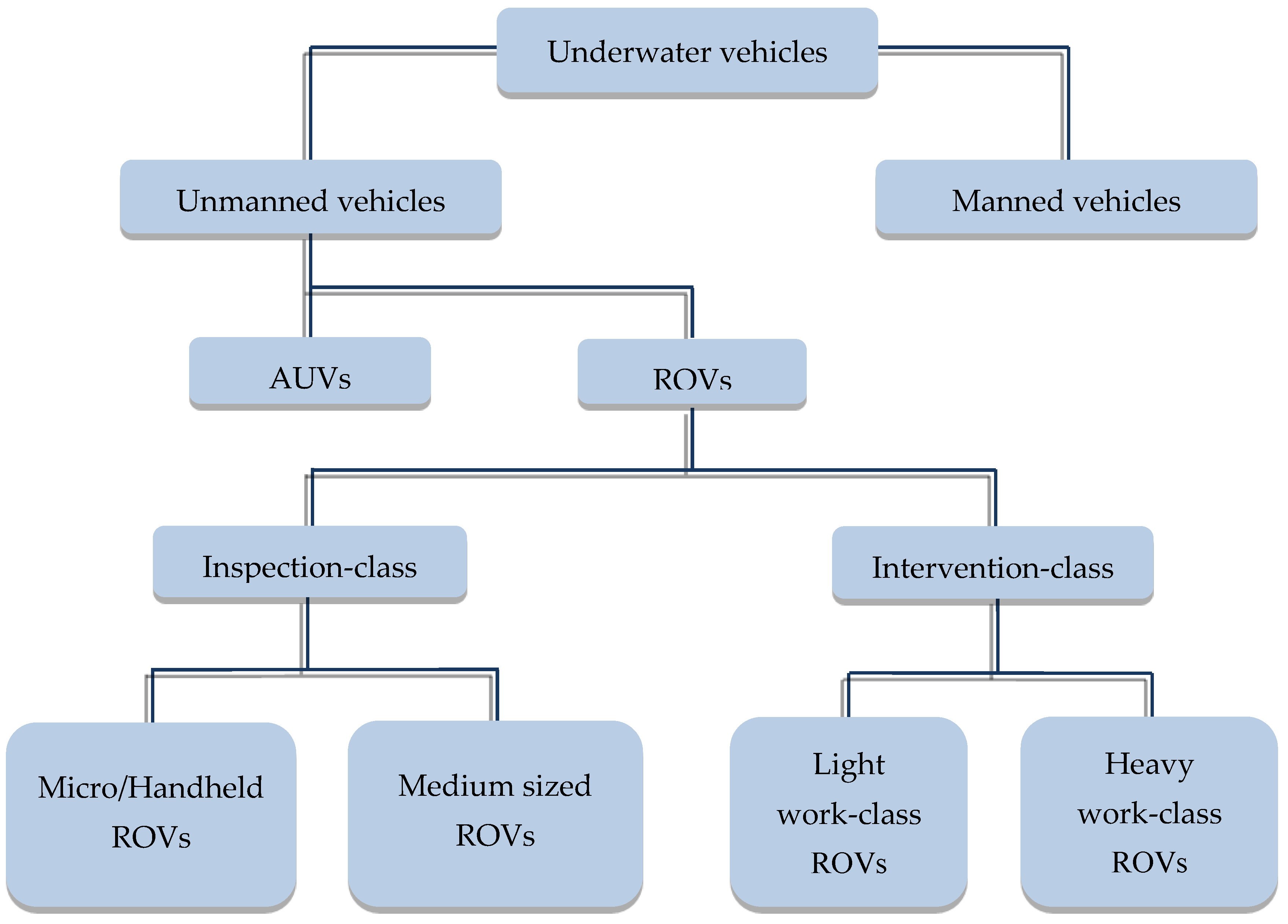
Inspection-class ROV shapes are varied and individual, with the most common design being the open frame type, which is widely used in the medium sized range. Other shapes, particularly in the micro range, can be varied and focused on the hydrodynamics of the vehicle.
The open frame design utilised by the majority of medium size ROVs aids the stability of the vehicle which is related to the distance between the centre of gravity and the centre of buoyancy, otherwise known as the metacentric height [11]. The centre of gravity (CG) of an object is the apparent point at which all of the weight is centred. The centre of buoyancy (CB) relates back to Archimedes’ principle. It is the point at which all the buoyant forces are centred. If the displaced water from the object could keep its shape, then the CG of this displaced water is equal to the CB of the object. The location and values of the CG and CB is related to the shape, weight and volume of the object.
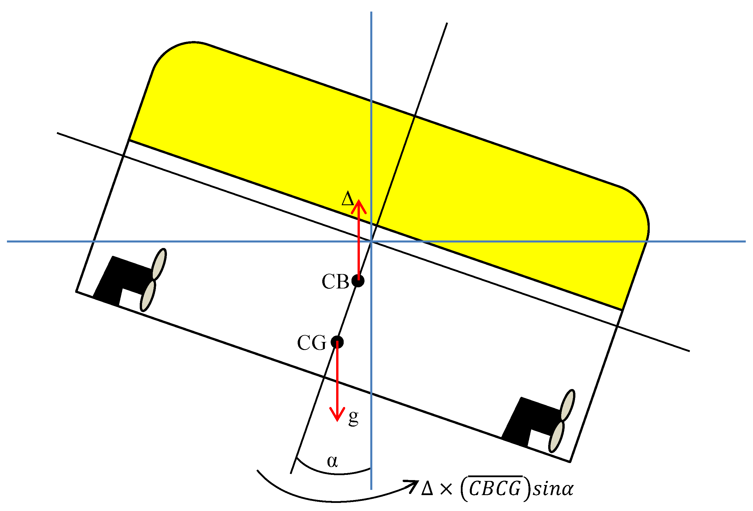
In general, the CB should be located above the CG; otherwise the object will rotate to try to right itself. According to Wang and Lu [12], when an ROV is subjected to changing water flow or changes in thruster forces it can incline along the x or y axis. A righting moment initiated by gravity, g and buoyancy force, Δ restores the vehicle to its upright state as shown in Figure 2.
Ocean Modules [13] represent a new trend in the inspection-class ROV industry by developing an ROV with the CB and CG located at the same point in the vehicle. This design has no restoring forces meaning that it has no inherent stability, allowing for 360° freedom of movement and various operating modes.
The shape of the vehicle is dependent on its buoyancy, frame, function and payload.

4.1.1. Buoyancy

To achieve buoyancy in an ROV, buoyancy blocks or modules, which are constructed of material that have density lower than water, are utilised. The buoyancy material must also be able to withstand the pressure applied when operating at depth.
Rigid polyurethane foam is a low cost material that is extensively used for ROVs with low operational depths, i.e., inspection-class ROVs. Rigid polyurethane foam is the term used to describe the category under which two different types of polymers fall: polyisocyanurate (PIR) and polyurethane (PUR). These two polymers are distinctly different.
For ROVs with the lowest operational depths, PUR is the preferred option as it is inexpensive and can be modified with ease. One constraint is depth rating; according to Trelleborg [14], they only have a depth rating of up to 250 msw (metres of sea water), with a protective, polyurethane elastomer skin. PUR is used primarily in floats for pipelines, pontoons, cables and hoses where they are required to be positioned on the surface of the water.
PIRs are produced using a chemical reaction and mixing isocyanate, catalysts, blowing agent and surfactants, modified with polyurethane. The resulting mixture is poured as a liquid between metal faces. The liquid expands to form solid cellular foam that bonds to metal faces to form a continuous panel [15]. It can then be cut and adjusted such that it meets the specifications of a particular ROV project. As it has a high percentage of closed cells and it is highly cross-linked, PIR offers dimensional integrity over a range of thermal values and pressure values. This is extremely important if an ROV is to “fly” at larger depths [16]. However, a primary disadvantage is its high thermal insulation values which must be accounted for in the design of the ROV.
Another type of polymer that is used for shallow-water applications is polyvinyl chloride (PVC) foam. Oceaneering, the world’s largest ROV manufacturer, uses a type of PVC foam in some of its ROVs. The foam used is called Divinycell HCP by DIAB [17]. The foam is generally coated with high strength skins. These skins offer the foam stiffness and strength while the foam maintains the buoyancy characteristic. The material can be easily machined but careful consideration must be taken to ensure that machining does not cause high temperatures, which can cause plastic deformation. The maximum depth rating of PVC foam is 700 msw.
Co-polymer foam is capable of operating at up to 600 msw due to its rigid, cross-linked, close cell structure. However, careful consideration must be taken in terms of density levels and depth ratings of the material. At lower densities the material may be suitable for short term applications, but if it is left under hydrostatic pressure for long periods, the material will deform, reduce volume and, ultimately, decrease buoyancy. Griffiths et al. observed reductions in buoyancy of the AUV Autosub-1a at depths of 504 m [18]. This reduction in buoyancy was related to the compression of the co-polymer when subjected to pressure and low temperatures. To minimise this creep, the co-polymer foams must be de-rated from their maximum capability. For example, if a co-polymer foam is to have a design life of 25 years, the de-rated value may be as little as 50% of its maximum depth rating. A polyurethane elastomer coating can also be applied to the surface for extra mechanical protection [14]. In more recent years Sakagami et al. [19] developed a human-sized ROV using a co-polymer in the dynamic buoyancy system, which uses a gearing system to rotate the buoyancy blocks for pitch control of the vehicle and manipulator arms.
For deep-water missions more advanced products are employed. After using gasoline-filled chambers for the Trieste mission, where Don Walsh and Jacques Piccard descended to the Challenger Deep in 1960 [20], syntactic foam became the new norm for deep water operations. Syntactic foam is a composite material which is made by inserting large quantities of hollow, glass, microspheres into an epoxy resin to create a single material. The term “composite” is sometimes used to describe this type of foam due to its use of different materials. However, the blocks are formed using dedicated mould tooling and machinery and are often used in multi-build ROV contracts as costs can be high for individual designs [21].
Because of its low density and ability to withstand high pressures without altering its composition, syntactic foam is typically selected for deep and ultra-deep water applications [22,23]. Technology has improved immensely; initial depth ratings of 1800 m were achievable in 1964 [24] compared to depth ratings in excess of 10,000 m, created by BTMI in recent times [25]. Additionally, the vast majority of syntactic foams are rated to 6000 m which represents about 95% of Earth’s ocean depths [26].
A recent study conducted by Poveda et al. [27] found that, after long periods subjected to water immersion, the glass microspheres in syntactic foam can degrade, reducing the strength by about 30%. This effect occurs when water ingress penetrates to the interface between the glass microspheres and the epoxy resin and then de-alkalisation takes place, allowing water to ingress into the glass microspheres. For longer term deployments alkali-free microspheres are available.
Another advancement in buoyancy is ceramic sphere technology, offering extremely large compressive strength and material weighs about half that of stainless steel. The spheres are manufactured by pouring the aluminium oxide mixture into spherical moulds and then passing the sphere through a number of drying and firing stages. They are manufactured so that wall thickness is kept to a minimum and uniform throughout the sphere, negating any weak spots.
Woods Hole Oceanographic Institution developed a deep-sea exploration vehicle Nereus, which successfully dived to Challenger Deep in 2007. This vehicle utilised 1472 spheres with an OD of 91 mm, producing a net buoyancy of 417 kg [28]. These spheres were developed by Deepsea Power & Light [29].
In a 2016 study Jiang et al. [30] noted that they could produce ceramic spheres for 1% of the previous reported product price and that these spheres could replace the use of plastic and glass microspheres.
All of the above technologies mentioned are fixed buoyancy. There is also an option for dynamic buoyancy systems for ROVs and underwater vehicles, sometimes known as active ballast. In a 2013 report Yu et al. [31] proposed the use of active ballast on a handheld ROV which can be deployed from an AUV. This active ballast is used for recovery of heavy items. In 2015, Wood et al. [32] developed an automated buoyancy control system for an underwater crawler. This type of buoyancy is preferred in a vehicle that, inherently, needs to sink in order to operate and then float for recovery. In an ROV, active buoyancy may allow for more efficient use of thrusters and preserve power, which was the motivation for Love et al. [33] to implement the system into the Tethra submersible.
As the inspection-class ROVs are generally used at maximum depths of 300 m the future will see the continued use of PUR materials for low operational depths as it is inexpensive. For slightly deeper applications PIR, PVC or co-polymer material is available. However, if the vehicle is to be docked permanently underwater or spends extended periods underwater, low density co-polymer foam may not be suitable due to the possibility of deformation, thus reducing buoyancy.

4.1.2. Frame

The frame of an ROV is used to mount equipment and provide support and protection during operations. The majority of ROV manufacturers use open frames for stability and ease of addition of auxiliary equipment and these frames offer unobstructed water flows to the thrusters.
Some ROV manufacturers have used novel methods by integrating essential equipment for the ROV to act as (part of the frame. For their Pro 4 ROV, VideoRay use the pressure housing bottle, used to house the control and power equipment for the ROV, as the structural frame. The three thrusters, two lights and skids and the buoyancy block are all attached directly to this pressure housing [34].
Other manufacturers produce their ROVs in one integrated module, meaning that there is no real distinction between the frame, the buoyancy, the pressure housing and the propulsion system. An example of such a system is the AC-ROV 100 that is manufactured by AC-CESS [9]. Often, a disadvantage of this type of frame is the drag it creates due to its block structure. In all directions there is little flow through the frame and the block structure increases form drag as the fluid passing over it separates rapidly causing a turbulent flow regime.
The type of material used for the frame is an important decision to make for the design engineer. The material must be capable of withstanding harsh conditions whilst also providing enough structural strength so that it can support the equipment of the ROV.
Typically, 6061-T6 aluminium or 316 stainless steel is employed on large, heavy vehicles such as the “ABISMO” ROV, developed by JAMSTEC [35], but it is also utilised on smaller inspection-class vehicles; Aras et al. [36] developed a vehicle weighing just 18 kg, with a full aluminium frame and Mariscope [37], the German ROV manufacturer, develop their FO II ROV frame completely in stainless steel and aluminium, which allows for a lifetime warranty to be provided with the ROV.
Using metal for the frame of an inspection-class ROV may not be ideal due to increased weight and degradation after long periods of contact with seawater. For this reason, polymers have become increasingly popular for frame material. Acrylonitrile butadiene styrene (ABS), high density polyethylene (HDPE) and polypropylene (PP) are common among ROV manufacturers. In 2015 Pranesh et al. [38] carried out finite element analysis on a polypropylene material to investigate if the material could be utilised for an ROV. Results were positive but the team also adapted their design to accommodate L-brackets at weak locations. This approach may be undertaken in other ROV design situations. Manufacturers of common inspection class ROVs have been integrating polymer materials into their vehicles, the varieties of which can be seen in Table 2.
An advancement in polymer material is the carbon fibre reinforced plastic (CFRP) which has a higher specific stiffness, strength and material damping than conventional polymers. Recently this material has been utilised in a project carried out by a team in the Korea Institute of Ocean Science & Technology where they constructed a frame for a seabed robot. This frame successfully supported the weight of the overall vehicle, which was 500 kg [39]. The use of CFRP in the ROV industry is expected to grow in years to come.
Since the majority of inspection-class vehicles are man-portable, their weight in air is generally below 70 kg. This weight can be supported with polymer materials. The future will see the continued and expanded use of polymer materials because of the benefits of low weight, no degradation in water and low cost.

4.1.3. Hydrodynamics

For work-class ROVs, little emphasis is put on hydrodynamics. This is because they are not designed for speed through water. They are work horses designed to use their high power to carry out heavy duty work. When the ROV size is reduced and the vehicle has to operate in more energetic environments the need for hydrodynamic analysis in design increases.
Medium class inspection ROVs are of a general box-like shape, with a buoyancy block on top and the thrusters and equipment slung beneath on the vehicle frame. This arrangement provides for good stability providing vertical separation of the centre of gravity and the centre of buoyancy [11]. Additionally, in acoustic imaging surveys, stability is important so that the data recovered has minimised noise due to fluctuations in the vehicle pitch and roll movements. One oddity in this category is the Ocean Modules’ V8 M500 ROV [13], which is designed in a way that the centre of gravity is coincides with the centre of the vehicle, allowing for rapid reaction to disturbance in any direction but reliant on active control systems rather than static stability. Forces due to tether drag, swell and current are automatically compensated for in the control system.
Over the years, developments have been made to decrease the drag experienced by inspection-class ROVs, most evident in the handheld inspection class category [40,41,42]. As the smaller ROVs are generally used as “flying cameras” stability is not the main design constraint so more novel shapes can be employed. One such novel shape is the eyeball ROV that was developed by Rust and Asada [43]. This ROV allowed for movement in any direction using an internal gimbal and eccentric mass mechanism.
In recent years more research has been conducted on the movements of marine mammals and fish. Researchers are looking to imitate the movements of fish for more efficient use of power and for observing fish in their natural environment without frightening them. According to Yu and Wang [44], the propulsion system for some fish is up to 90% efficient, while a conventional screw propeller has an efficiency of 40%–50%.
Most biomimetic fish robots can imitate a type of fish in a specific swimming mode—either cruising or manoeuvring. For advanced control, the robot should have options of switching between swimming modes. At the University of Canterbury, New Zealand, a research team designed a fish robot that could alternate between the two swimming modes by changing the behaviour of the pectoral fins during operation [45]. Akanyeti et al. [46] describes a rainbow trout inspired robot where they mimicked the fish’s lateral line flow sensing organ through use of MEMS strain gauges. The svenning (flow sensing for fish) was then translated into the required actuation for the fish to swim.
Salumäe et al. [47] have developed an AUV that is inspired by the movements of turtles which can be used for shipwreck penetration and assisting archaeologists. In 2016 the U.S. Navy have sanctioned a significant grant to the Florida Atlantic University to develop an underwater robot that mimics a knifefish [48].
Sepios [49] is a cuttlefish inspired ROV with actuation through use of four fins. These fins allow for movement in and around seagrass and other marine vegetation without the risk of entanglement of vegetation in thrusters.
In situations where the current may be too strong for swimming robots, crawling or walking robots may be utilised. Kim and Jun [50] describe the development of a crab-like ROV. This walking ROV would allow for visual inspection at high current sites. At the School of Marine Science and Technology in Newcastle University, UK they developed a multi-legged skid that could be retro-fitted to an ROV for tidal current pipeline inspection [51].
Computational fluid dynamics (CFD) software is now commonly employed during the design process of such ROVs. Nguyen et al. [52] explained how they utilised CFD to verify the coefficients used in design calculations and Long et al. [53] employed CFD for validity measurement of a grey-box based parameter estimation approach to controlling an ROV.
As commercial products are focused on ROV capabilities and increasing applications the near future will continue see ROVs being produced with more emphasis on hydrodynamic analysis during the design process. With the growth in the marine renewable energy industry inspection-class ROV vehicles will be expected to operate in more extreme environments, meaning that, among other design criteria, ROV drag must reduce. Also, for the near future biomimetic robots, will not see any traction in the commercial side of the industry. Although novel, a lot more research needs to be carried out in order for the systems to have a chance of commercialisation. As of now their capabilities are too minimal. They will continue to be developed but for the coming years that development will be in the research field only.

4.2. Power Systems

Power systems for inspection-class ROVs can be subdivided into the tethered systems, employed by the majority of the inspection-class category and the battery fed systems, which are more common in the handheld category.
Hydraulically driven ROVs are outside the scope of this review and are not considered in detail. However, size of the hydraulically driven, light work-class ROVs is being reduced and in the future we may see inspection-class ROVs using hydraulic systems on the ROV wet end with hydraulic power packs converting electrical energy to hydraulic.

4.2.1. Tethered Power System

As the market sector of ROV power systems is small within electrical power systems more generally, many developments in ROV tether power has followed from developments in technology elsewhere being transferred into ROV technology. Much of the wet end equipment on ROVs utilises DC power at low to medium voltages. However, low voltage DC transmission from the top to bottom side would require large conductor cross section choice in the tether to minimise ohmic power losses. AC power transmission systems employing step up transformers at the sending end (top side) and step down transformers at the receiving end (wet end) have facilitated reductions in the cross section of power conductors in tethers. With the large size and weight of conventional 50/60 Hz power transformers, many ROV designs have opted for high frequency AC systems as used in the aircraft industry which give a significant size and weight reduction for a given power rating in transformers. With the development and uptake of solid state DC-DC converters enabling DC voltage step up and step down, recent trends in ROV power systems has adapted high voltage DC transmission through tethers.
According to Whitcomb [54], tethered ROV power systems are dominated by cable limitations and over 50% loss can occur in longer cable runs.
Depending on the type of ROV and the length of the umbilical the power system can be either AC or DC. Generally work-class ROVs send AC through their umbilicals, converting to DC on the bottom side for some components. AC tethers have been used in longer tether transmission runs, resulting in higher operating depths for the ROV. Furthermore, as size of the work-class vehicles is not critical they can easily support the heavy transforming equipment bottom side. High voltages are sent down the umbilical to ensure that electrical losses are minimised. For example, the ROV ROSUB 6000 [36], sends down 6.6 kV at a frequency of 460 Hz through its 6000 m umbilical. As ever, there are exceptions to the voltage applied to work-class vehicles; the LAURS ROV uses a DC power supply which generates 4.5 kW [55].
The use of high frequency AC power is implemented because the size and weight of transforming equipment on the ROV side can be reduced. According to Snary et al. [37] a reduction in transformer mass of up to 66% can be achieved by increasing operating frequency from 60 Hz to 400 Hz. Saab Seaeye produce the Leopard ROV which transmits 3000 VAC at a high 800 Hz, significantly reducing the size of wet end transformer and the cross section of the conductors in the umbilical [56].
In applications where the umbilical is long a winch is required for management. When a winch is employed a slip ring is also required. A slip ring, also known as a rotary joint, is an electro-mechanical/optical-mechanical device that is used to transmit electrical/optical power or signals from a fixed piece of equipment through a rotating joint. This piece of equipment is essential to allow for continued power/telemetry to flow to/from the ROV during the rotation of the winch. If the umbilical is made of purely copper conductors the slip ring is a simpler construction consisting of brushes and rotating metal rings. However, if the umbilical houses fibre optic cores the slip ring becomes more complicated, and expensive. Various manufacturers offer electro and optical slip rings like Moog and Trolex [57]. Slip rings, both electro and optical can allow transmission of various cores, called passes. In many situations additional fibre optic passes on the slip ring/s and cores are introduced to the ROV system to allow for redundancy, e.g., as described by Vedachalam et al. [58] and Zhang et al. [59] in recent studies. This allows for continued operation and communication of ROV if one fibre is damaged.
In the larger ROV systems launch and recovery systems (LARS) and tether management systems (TMS) are employed due to the large size of vehicles and umbilical tether winches.
Bowen et al. [60] describes how WHOI have developed a system which aids in the reduction of large winches and TMS. The system makes use of a combination of optical and acoustic sensors to allow a pilot to carry out intervention applications.
Although less common, inspection-class ROVs with an AC power supply have been designed; the Underwater Systems and Technology Laboratory in the University of Porto developed an ROV that transmits 230 VAC through the tether, converted the AC to 375 VDC on the ROV side and then carried out a further conversion to 48 VDC for thrusters and equipment [61]. The Underwater Robotics Research Group in the University of Malaysia have also developed an inspection-class ROV which sends AC voltage to the vehicle [62]. The use of 230 VAC resulted in reduced current and losses through the umbilical. It is common to use fibre optics in AC umbilicals as the AC power can cause significant noise in the communications lines, unless properly shielded.
DC power in inspection-class vehicles is more common for a number of reasons:
  • Size
  • Cost
  • Depth rating/length of umbilical
  • Power requirements
  • Complexity
Stipanov et al. [63] described how a modified VideoRay Pro II used as an AUV transmitted 48 VDC through to the vehicle, using 48 VDC directly for thrusters and lights and using a DC/DC converter to step down to 5 VDC for electronic components. For vehicles with small power requirements this may be suitable.
However, as power demand is increased the voltage transmitted down the umbilical must also be increased. At the Center for Engineering and Industrial Development in Mexico a team developed the Kaxan ROV, which is in the medium size inspection-class ROV category (90 kg), using a 150 VDC transmission system [64]. Some commercial manufacturers also develop ROV systems with similar transmission voltages. Teledyne Stingray (150–300 VDC) and Outland Technology 1000 (165 VDC) are some examples [65].
In recent years the trend has been to step the 230 VAC up to a 400 or 500 VDC (medium voltage) on the topside and transmit down to the ROV, converting down to the required DC voltages bottom side. This approach has been adopted in many oceanographic observatories with the transmissions down to the primary junction in the order of kVs and then secondary nodes at 400 VDC supply [66,67,68]. The 400 VDC is then converted to the working voltages of electronic equipment and sensors (48 VDC, 24 VDC, 12 VDC, etc.). By stepping the voltages up to higher DC allows for reduced I2R losses in the transmission cables, thus allowing for longer umbilical lengths and/or reduced diameter of umbilical. NETROV, a research ROV designed by Robu et al. [69] transmits 400 VDC down their 300 m umbilical. Seatronics also transmit 400 VDC for their Predator II ROV [70] and Saab Seaeye send down 500 VDC for the Falcon ROV [71].
The benefits of utilising a tethered power system are the unlimited operation times and the ability to use computer resources top-side, reducing mass and volume of the vehicle. There are also drawbacks; a report, carried out by Dowling [72], states that the overall ROV system size is increased, tether management requires additional manpower and/or mechanical equipment and the system and operation costs are increased.

4.2.2. Battery Powered System

Battery powered systems are used extensively in AUVs but are less commonly used in ROVs. However, on board batteries can offer an alternative to tethered power systems. Dictated by life cycles and chemical reaction processes, batteries can be split into two categories:
  • Primary batteries—this type of battery, once discharged, cannot be recharged. The most common type of primary battery is the alkaline. They have an energy density of up to 140 Wh·kg−1. They are inexpensive and safe, however, they have a tendency to outgas hydrogen when stored for long periods [73]. Lithium cells offer energy densities of up to 375 Wh·kg−1. They also have a longer shelf life and endurance. Costs are higher and they should be used with special caution as some types have been seen to explode violently [74]. However, lithium cells are less common in power systems for underwater vehicles today because of cost implications.
  • Secondary batteries—this type of battery can be recharged many times, increasing the usable life. They are used extensively in the AUV market and some ROV/Hybrid ROV systems utilise this type of battery. Different chemical reactions include lead acid cells, silver-zinc cells, nickel-cadmium (ni-cad) cells, and lithium-ion polymer cells. Lead-acid cells are simple and inexpensive, but large and heavy. Silver-zinc cells offer a high energy density, but they are costly and have short with lifetimes, about 100–250 cycles. Nickel-cadmium batteries are ideal for applications where high current is required. They are inexpensive but heavier than the others. Lithium ion cells are small in size, and offer higher energy than other cells. They are the most expensive and careful charging must be employed to ensure that burning or explosions are avoided [12].
For some ROV applications the use of batteries may be more suitable. Bowen et al. [75] designed a battery powered ROV for oceanographic research under ice. The system employs an extremely small diameter fibre optic umbilical of lengths up to 20 km. This allows for the ROV to fly under ice shelves, even when the ship’s movement is constrained by ice.
Another application for battery powered ROVs is in high risk environments. If, for example, the ROV tether became entangled in this environment it could be cut and the ROV, now operating as an AUV could return to a predetermined area for collection. The centre for Marine Environmental Sciences MARUM developed an ROV for such instances [76]. The “Jake and Elwood” ROVs used during the filming of the Titanic movie “Ghosts of the Abyss” also utilised this fibre optic approach, where they would spin a web of biodegradable fibre optic in their wake and, upon returning to their sister ROV, the fibre would be severed.
Due to their small footprint, micro inspection-class ROVs often make use of battery power. The combination of small umbilical and ROV size results in less drag, allowing for longer mission times. Some examples are shown in Table 3.
The major drawback of using a battery operated system is the operating time, which is dependent on the battery output and life. To overcome this challenge wireless charging underwater may be a solution. The research conducted to date has focused on AUV technology. As part of the ALOHA-MARS Mooring (AMM) project a docking system was developed and trialled for AUV battery charging [81]. To allow for prolonged endurance or permanent housing of subsea ROVs this charging approach may be suitable.
The Department of Systems Engineering and Automation in Murcia, Spain developed an AUV that is charged by solar power. The AUV is connected to a surface vehicle via a tether. As the AUV navigates it tows the surface vehicle, which contains PV solar panels [82]. Used in conjunction with an ROV this method could replenish power, aid in navigation and allow for wireless remote communication and control of the vehicle.
Chao [83] describes a novel energy storage station that is powered by ocean thermal energy through the use of Phase Change Materials (PCM) at various temperature gradients. This novel approach could also be utilised for wireless charging as was discussed previously.
For increased endurance fuel cells may be utilised but will require significant research in order to develop the technology for underwater vehicle use. According to Mendez et al. [84] only a handful of AUV prototypes using fuel cells have been developed.
ROV and sensor capabilities are ever increasing. With increasing function the power requirement is generally increased. Future trends will show that the ROVs requiring high power to operate in strong conditions, whilst needing strong control will always require a tethered power system. There will also be a requirement for the battery operated vehicles, not just the hobbyist applications. Under ice exploration is one such application where a battery operated vehicle may be better suited.

4.3. Telemetry/Umbilical

This section is split into the transmission hardware and the communication protocols.

4.3.1. Transmission Hardware

Wireless underwater data transmission cannot be used for control and communication of an ROV due to low transmission rates possible over range through water. Palmeiro et al. [85] state that for underwater electromagnetic signals maximum transmission rates of 10–100 Mb·s−1 are possible at a range of 0.2 m in seawater and when the distance is increased to 200 m the transmission rates are as low as 50–100 b·s−1. There are other forms of underwater communication like acoustic or optical but there are also limitations prohibiting their use for ROV applications.
In general, due to limitations in wireless technologies, communication is usually fed through a tether/umbilical. The transmission mediums for comms are metallic conductors or fibre optics. The metallic conductors are generally made from copper due to cost and can be in the form of twisted pair or coaxial cable.
Twisted pair cables are the most commonly used for comms in ROV applications. They consist of various numbers of wire “pairs” twisted uniformly throughout the cable. The twisting reduces the level of induced crosstalk or noise. This type of cabling is called unshielded twisted pair (UTP). Further reduction in noise can be accomplished by shielding each pair (STP). Twisted pair cables are used for Ethernet networks. The types of cables are differentiated by their category. The types used for Ethernet networks are generally Cat 5 or above. Transmission rates for Cat 5 is in the order of 1 Gb·s−1 [86]. Although these cables have a maximum transmission length recommended by the manufacturers of 100 m, inspection-class ROV designers often employ them at distances of up to 300 m, albeit with reduced bandwidth.
Very-high-bit-rate digital subscriber line (VDSL) technology allows for large bandwidth through standard twisted pair hardware. The technology uses frequency division multiplexing to allow for symmetrical and asymmetrical data transmission. Early systems allowed for up to 25 Mb·s−1 symmetrical data transmission over 740 m [87]. However, with the advancement to VDSL2 technology rates have been increased to 100 Mb·s−1 symmetrically and asymmetric transmission of 100 Mb·s−1 download and 50 Mb·s−1 upload over a distance of 2 km [88]. Further enhancements have been made in more recent years, with research being carried out to bridge the gap from homes to the main fibre node connection of areas where fibre to the home (FTTH) is not possible. Next generation technologies include G.fast, Vplus and XG-fast (prototype) [89,90,91]. Currently these are topside technologies but could overlap into subsea and ROV applications in the near future.
Table 4 summarises the characteristics of the various transmission technologies:
Marine sensor manufacturers are now producing equipment that can utilise the larger VDSL data throughputs. Examples are Kongsberg, Teledyne BlueView and Tritech.
Some underwater sensors are introducing devices that have changed over from serial communication technology to Power Over Ethernet (POE), which provides power and comms over a single Ethernet network cable. The original IEEE 802.3af-2003 POE standard specified 15.4 W at 48 VDC to each device however due to losses in the cables only 12.95 W could be delivered at the device end [92]. In 2009 a revised standard was introduced for POE+, IEEE 802.3at, specifying 30 W at 50 VDC, with working power at 25.5 W after cable losses [93]. These standards use only two of the four pairs available in the network cables. However, IEEE currently have a working group working on proposed standard IEEE 802.3bt, which will allow for the use of all four pairs leading to higher power capabilities [94].
Another form of data transmission is Ethernet over Power also known as Powerline networking technology. It allows the transmission of communication data through power conductors. Power supply companies have been using this idea for years, by sending signals down transmission lines to distinguish between peak and off-peak rates. This technology has been redesigned for home networks where the technology is retrofitted to existing power conductors around the house, making the technology more affordable. The latest adapters are rated for up to 2Gb·s−1 at a range of up to 300 m [95], but in real world tests the data transmission rates are greatly inferior with an independent reviewer finding speeds of just 117 Mb·s−1 over 30 m [96]. In a paper produced by Cazenave et al. [97] they discuss how they used this Ethernet over power technology for an ROV designed for exploration of under-ice environments. They found that the technology had the ability to transmit 60–80 Mb·s−1 across 400 m of 18 AWG twisted pair.
Coaxial cables, because of their construction, are suitable for applications where high frequency transmission is required. Transmission rates of 10–100 Mb·s−1 can be achieved over distances up to 500 m [88]. Some early inspection-class ROVs utilised coaxial umbilicals in their design, like the first GNOM, developed by Rozman and Utyakov [81] but use of these systems have reduced over the past number of years with the advancements of fibre optic technology.
Fibre optic technology has become an industry standard in the work-class ROV field. This is partly due to the immunity from AC power line induced noise on to the fibre optic transmission and partly due to the large bandwidth available at the larger distances.
Single mode (SM) and multimode (MM) fibres are both suited to ROV applications, however limitations in MM transmission systems (Gb·s−1 up to 550 m length and 10 Gb·s−1 capable of distances of 300–400 m) [98,99], and reduced cost of SM systems in recent times means SM has become almost industry standard.
In the past, SM equipment required one fibre for transmitting and one for receiving, termed simplex. Now full duplex systems are utilised that can accommodate bi-directional communications. To allow for bi-directional and increased transmission communications, multiplexing is used, where multiple signals can be sent down a line simultaneously. In the fibre optic field wavelength division multiplexing is a common technique whereby separate signals are transmitted through the core at different wavelengths called channels [100]. As channels increase so too does the transmission rates. There are two wavelength division multiplexing transmission techniques—coarse wavelength division multiplexing (CWDM) and dense wavelength division multiplexing (DWDM) which can be viewed, along with their characteristics, in Table 5 [101,102].
According to Nebeling [103] the cost difference is related to the tighter tolerances related to the manufacture of lasers and transceivers, the larger number of filters required and the operating costs due to active cooling required in the DWDM equipment. Even though there can be huge transmission rates achieved through the DWDM multiplexing it is rarely used for ROV applications as the technology and cooling equipment is large and bulky and transmission rates are largely dictated by the Ethernet or serial output from many sensors (max. 1 Gb·s−1). Instead CWDM multiplexors are utilised for creating numerous channels for sonar, HD camera/s, navigation and control and various other sensors. Choi et al. describe a system based around a CWDM multiplexor to increase efficiency and productivity of a smart ROV [104].
As stated previously, data transmission through fibre optic to/from ROVs is limited by the bottleneck in the system, either the Ethernet or serial output from sensors. HD and 4K cameras are now being produced with allowances for direct connection of fibre to the camera using SFP/SFP+ (small form-factor pluggable) transceivers, Blackmagic Design being an example [105]. SFP transceivers can be used for transmission rates of 1–10 Gb·s−1 over distances up to 10 km for a single core fibre [106], but the limitation may then be at the multiplexor at the higher rates of 10 Gb·s−1. This technology could be integrated into underwater applications and sensors where lack of data throughput is a concern.
Some inspection-class ROVs use multiple HD cameras and/or sonar systems, along with control and navigation equipment. For these ROVs it is important that a large bandwidth is provided for data throughput. Fibre optic is beginning to become more prevalent in inspection-class ROVs. Research driven ROV projects often utilise fibre optics for communications [107] and some manufacturers also offer fibre cores as optional upgrades [108].
Generally, cores of the umbilical are surrounded by a reinforcing material which gives the cable its working strength. At a minimum the cable must be able to withstand the dry weight of the ROV, as the ROV is generally recovered using the umbilical. A number of cable manufacturers, like Macartney, offer Kevlar braiding as the strength member in some of their stock umbilicals [109].
Since the number of sensors that is utilised on ROVs is constantly increasing, the future will see the demand for higher bandwidth increasing. One prediction is the use of sensors with direct fibre connection, thus eliminating the bottleneck of serial or Ethernet transmission. As terrestrial transmission technology continues to push for higher bandwidth through copper material, this may also be utilised in the ROV industry, reducing the need for costly fibre equipment.

4.3.2. Communication Protocols

The field of networking and communications is filled with communication protocols. According to Stallings “Each protocol provides a set of rules for the exchange of data between systems” [110]. The ROV industry has adopted a number of robust standards that have been employed in industrial applications, the most common are discussed here.
Recommended Standard 232, more commonly known as RS-232, was developed in the 1960s for transmission between data terminal equipment (DTE) and data communications equipment (DCE). It defines a logic 1 as a voltage between −3 and −25 V and a logic 0 as a voltage level between +3 and +25 V [111,112].
RS-485, introduced in 1983, defines a logic 1 as a voltage between −1.5 and −5 V and a logic 0 as a voltage level between +1.5 and +5 V. It is a multi-drop configuration, connecting multiple devices together, in a master, slave configuration [112,113].
Ethernet is a physical layer protocol used for transporting data across the physical layer of a network. It is the most widely installed local access network (LAN) technology due to its relative low cost, reliability and adaptability.
Table 6 presents a comparison of the three common communications protocols in use by the ROV industry today [111,112,113,114].

4.4. Thrust

Inspection-class ROVs are almost exclusively propelled by thrusters. Thrusters are essential and allow for the ROV to manoeuver through the water column, station keep, travel to desired locations and control the ROV in dynamic environments, such as operating in strong currents or in the splash zone.
Depending on the type of ROV system, the thrusters used can be driven either electrically or hydraulically. In inspection-class ROVs electric DC thrusters are used extensively and here are a number of different DC motors used:
  • Brushed DC motors
  • Brushless DC motors
  • Magnetically coupled motor
  • Rim driven motors
Brushed DC motors are generally cheap and easy to control. They require periodic maintenance and have a lower speed range because of mechanical limitations on the brushes [115]. ROV manufacturers have used them in the recent past, with Deep Ocean Engineering integrating them into their version III Phantom ROV [116], but advances in other DC motor technologies have made their usage quite rare nowadays. They are not the ideal motor to be used for thrusters as the enclosure needs to be opened to change brushes, thrust output is quite low and there is a high risk of water ingress at the output shaft seal. Nonetheless, brushed DC motor thrusters are still available for purchase today as they offer a low cost alternative.
Permanent magnet brushless DC motors do not require brushes as commutation is achieved through electronic controllers. According to Ishak et al. [117], they are the preferred option over the brushed DC motor when used in extreme conditions. They offer a higher speed range, less maintenance requirement, higher efficiency and better thermal characteristics. However, they do require an electronic speed controller (ESC) for control and are often higher cost. Additionally brushless DC motors generally need gearing to ensure efficiency.
Magnetically coupled DC motors are also known as outrunner DC motors. They operate on the same principle as brushless DC motors; the only difference being the rotor rotates outside the stator and torque is transmitted using magnetic forces, therefore no mechanical connection is required. This arrangement is perfect for marine thrusters as it allows the internal stator and electronic components to be easily sealed from water. The rotor can then slip over the housing and is locked magnetically with the propeller mounted on the rotor. As the magnetic fields in the stator rotate so too does the rotor/propeller. Thruster manufacturer Tecnadyne produces a number of magnetically coupled thrusters and Blue Robotics have recently entered the market producing a low cost, lower thrust version.
Another version of the magnetically coupled thrusters is the rim driven thrusters. They have been in development since the 1940s [118,119]. The design incorporates the stator magnets mounted on the external rim of the thruster. Inside, the rotor magnets are connected to the propeller. According to Cao et al., these motors offer many advantages over conventional shaft driven motors:
  • Compact
  • Higher motor efficiency
  • Higher hydrodynamic efficiency
  • Reduction in secondary systems [120]
The design also allows for the motor to be cooled, as the motor parts that are susceptible to heating have short thermal paths to the cooling water. Recently, rim driven thrusters have been developed by the University of Southampton [118,121] which TSL Technology Ltd. have a licence to produce commercially [122]. They produce thrusters of various sizes, ranging from 50 mm to 700 mm. Enitech are another manufacturer who produce rim driven thrusters [123]. Dunbabin et al. [124] developed flat rim driven thrusters to reduce the horizontal drag of their Starbug AUV. The thrusters are only 16 mm and by using them they have reduced the frontal area of the vehicle by 16%. Although there are benefits to using this technology ROV manufacturers have been reluctant to switch over to them.
Holt and White [125] proposed a design of two rim driven thrusters operating in a counter rotational fashion, eliminating the roll torque produced by a single thruster and Qiu et al. [126] expanded on this idea by prosing a novel single thruster, with the rotor and armature rotating in different directions. This may be a useful solution in single thruster driven vehicles, like AUVs.
Future trends will see the use of magnetically driven (shaft and rim) continue to increase due to their superior benefits over the traditional types of thrusters.

Thruster Configurations/Architectures

The level of control of motion of an ROV is dependent on the thruster configuration used within the vehicle. Factors influencing the type of configuration include size, available power, required thrust, degrees of freedom (DOF) required, payload, etc. DOF describes every combination of a vehicle’s movement. The movements are described as rotations and displacements about the Cartesian axes x, y and z. ROVs can have varying DOFs, depending on the orientation and number of thrusters on board. 
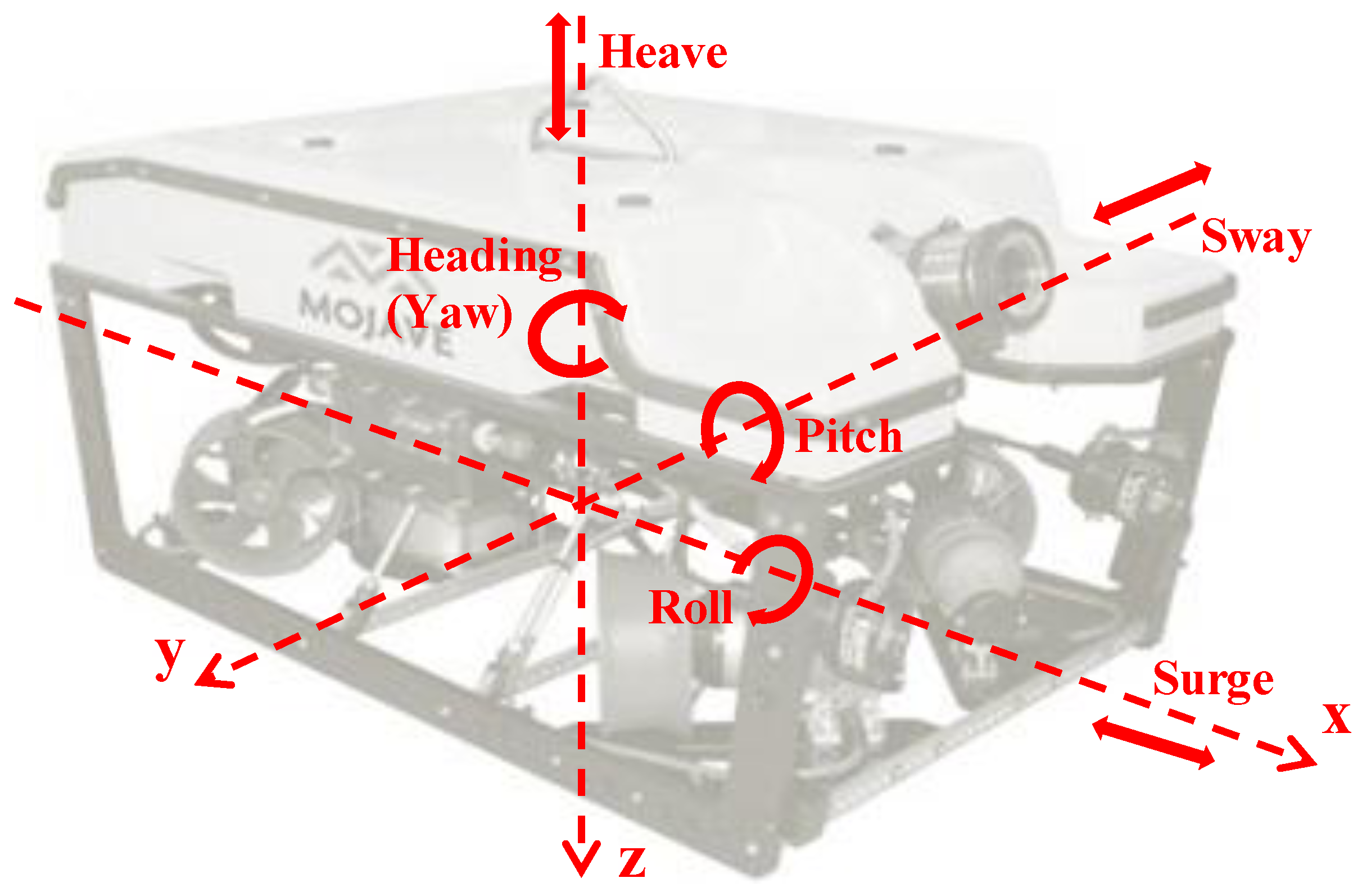
Figure 3 illustrates an ROV with the maximum number of degrees of freedom possible.
As can be seen in Figure 3, the ROV has six DOFs, meaning it is capable of movements in every possible orientation:
  • Heave—movement along the vertical plane
  • Surge—longitudinal travel along horizontal plane
  • Sway—lateral movement along horizontal plane
  • Heading—rotation about the vertical axis (z)
  • Pitch—rotation about the lateral axis (y)
  • Roll—rotation about the longitudinal axis (x)
Generally, ROVs have at least three thrusters, one vertical and two horizontal. This allows for heave, surge and heading control. The low number of thrusters limits power draw and thus umbilical rating and diameter. The VideoRay Pro 4 [34] and the Subsea Tech Sentinel 3.0 [128] employ this configuration of thrusters.
However, Deep Trekker offer an ROV with two thrusters that can be controlled for heave, surge and heading [129]. It makes use of their patented pitching system which is, essentially, a dynamic internal ballast. As the ballast rotates, the ROV can rotate to pitch up or down, allowing for heave control. The ROV is neutrally buoyant so it makes the ROV power usage quite efficient as there is no need for the constant use of vertical thrusters to keep the ROV at a desired water depth.
For extra control four thrusters can be used. The thruster configuration is generally one vertical thruster giving heave authority, one lateral thruster giving sway authority and two horizontal thrusters for surge and heading control. The Teledyne SeaBotix LBV150-4 [130] and the ECA H300 [131] ROVs employ this control architecture.
To enable six DOF at least six thrusters must be utilised. Generally, two horizontal thrusters for surge and heading and one for sway combined with three vertical controlling roll, pitch and heave. However this thruster configuration is not often used as it has limitations in surge and heading control.
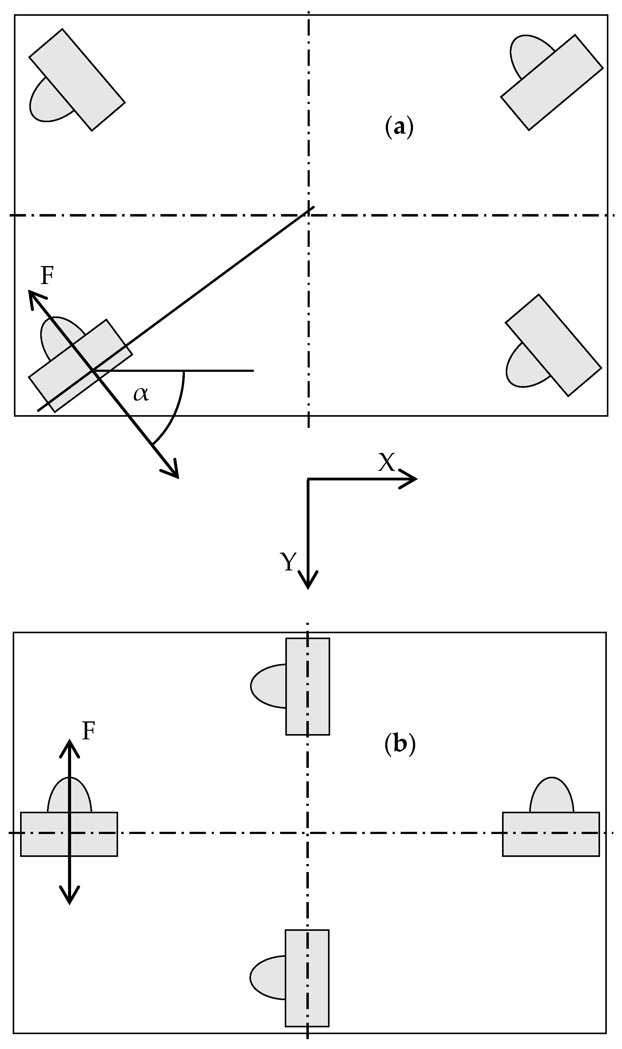
To allow for more accurate surge, sway and heading control, four thrusters, orientated in a vectored configuration can be utilised. This is one of the most popular methods of actuating an ROV today due to increases in control in all horizontal directions. The vectored thruster configuration as shown in Figure 4a shows a marked improvement over the non-vectored configuration (Figure 4b) in terms of surge and sway thrust capability.
The overall thrust in the vectored orientation is shown to be Tx = 4Fcosα, Ty = 4Fsinα, where F is force, and the two forward, two lateral orientation’s thrust can be calculated as Tx = Ty = 2F. If the vectored thrusters were orientated at 45° the thrust would be Tx = Ty = 2 2 F , which shows the greater thrust capabilities [132]. This vectored orientation also gives a higher level of fault tolerance [133]. In a paper by Omerdic et al. [134], they describe fault tolerant control of an ROV with the vectored orientation.
For the vertically orientated thrusters, either one, two, three or four thrusters can be utilised; one providing control over heave; two providing control over heave and roll; three allowing control over heave, roll and pitch; four allowing improved control over the three DOF with fault accommodation possibilities [134]. The vertical thrusters can be orientated either directly vertical or at an angle of 45° or less from the vertical. This allows for further control of movement in the roll or pitch rotations, depending on the orientation of the thrusters as they come closer to an orientation tangential to the centre of rotation. This method of orientation is called vertrans and is utilised by Seamor Marine in their Steelhead and Chinook ROVs [135]. Four vertical thrusters can also be employed if the vehicle is to be used for recovery of items/persons from a water column, allowing for extra thrust for a heavy payload.
Ocean Modules, along with designing their ROVs to be neutrally buoyant, use eight thrusters for complete control over the V8 M500 and V8 Sii models [13].
The number of thrusters and configuration used is totally dependent on the application, level of control required and biasing of control in a particular plane. Some ROVs may need the majority of control in the surge, sway and heading and very little control of the heave of the vehicle whereas other ROVs may need high control of the heave due to lifting and recovery applications.

4.5. Navigation and Positioning Sensors

As ROVs are controlled remotely it is important to understand their location in the water column. GPS signals do not travel through water so other systems are utilised and, depending on accuracy requirements, multiple sensors may be employed in parallel. Practically every ROV has a basic suite of sensors for heading and depth information. A fluxgate compass sensor is used for vehicle heading and often three axis fluxgate sensors are used, which measure the magnetic field in three dimensions. This array is known as a magnetometer and they must be calibrated in each axis so that the magnetic field produced by the ROV is subtracted from Earth’s magnetic field. Dynamic interferences created by rotating thrusters will cause unwanted noise and generally output rates in commercially available compasses are low, with Bandala et al. [136] reporting outputs of a few Hz and Dukan et al. [137] observing a delay of 1 or 2 s. This delay would be too large for real time control applications but they offer a cheap heading solution for less sophisticated ROVs.
Pressure sensors are used for depth feedback. The pressure sensing element may be made from a strain gauge or piezoelectric material which, upon being subjected to pressure, will generate an electric charge, vary resistance or alter the frequency of oscillation from sensor output. For low cost auto control functions on inspection ROVs the options are generally auto-heading and auto depth. The auto-depth function was utilised in an ROV, developed by Aras et al. [138], which utilised the feedback from a pressure sensor in a low cost system. Dubaibabu et al. [139] describe a fibre optic sensor that can be used for pressure and temperature underwater. The sensor was mounted on an ROV for testing and accuracy of between 1 and 3 cm was achieved. If higher tolerances are required, pressure sensors are available that can measure depth change from as little as 1 cm. In high accuracy sensors like this, drift can be an issue so Sasagawa and Zumberge [140] have developed a self-calibrating pressure recorder to reduce drift in a system used for recording crustal deformation on the seafloor.
An altimeter, also known as a single beam echo sounder, can be used for detecting an ROV’s distance from the seafloor using acoustic pulses. This sensor is useful if an ROV operates in an environment with little bathymetry detail. They are standard equipment in ROVs that have moderate positioning or control capabilities. Aras et al. describe a novel approach where they use a low cost fish tracker as an altimeter for an ROV, with accuracy readings of 90% [141]. Optical altimeters, using laser triangulation mapping, have been used for a number of vision based navigation, motion control and real-time mosaicking applications [142,143]. These applications offer very accurate positioning feedback but are only available at near-seafloor altitudes and in locations of low turbidity.
As tasks become more demanding tighter navigation tolerances are required, which demands more sophisticated technology. Use of dead reckoning sensors can assist in meeting this demand. From a known position they can offer robust and high frequency navigation feedback but will accumulate errors over time [144].
The most common form of dead reckoning used in subsea environments is the inertial navigation system (INS) based on micro-electro-mechanical sensor (MEMS) technology. The operating sensor inside an INS is an inertial measurement unit (IMU), which is typically made up of three accelerometers and three gyros. This sensor measures acceleration and rotational velocity. The INS is the complete package of IMU, controller and electronics combined. However, this type of technology can be highly prone to drift. According to De Agostino et al. [145], who carried out a comparative study on different MEMS-based IMUs, the largest drift errors are related to inertial sensor imperfections of the gyro and accelerometer. Bikonis et al. [146] integrated surface GPS positioning with an IMU, using an external Kalman filter, which produced more accurate positioning and Ko et al. [147] propose a system using a combination of depth measurement and MEMS-based IMU to enhance the accuracy attitude estimation.
Further positional accuracy can be obtained by using advanced ring laser (RLG) or fibre optic gyros (FOG). Both technologies are extremely accurate and, when integrated into an INS, offer lower INS drift because they are not affected by distortions to the Earth’s magnetic field, typical around man-made structures [148] and in areas with ferro-magnetic signatures in rock. RLGs have been commonly used in AUV applications, including the Jinbei, developed by JAMSTEC [149] and the Theseus [150]. They offer extremely low drift errors of better than 0.01°/h and mean time between failures (MTBF) in excess of 60,000 h [151]. To prevent a phenomenon known as injection locking where, under slow rotations the gyroscopes will not accurately measure rotation rates, the mirrors in the RLG are mechanically dithered [152]. This is a drawback of the RLG technology because it produces an audible tone, which can interfere with other acoustic sensors in the vehicle.
With recent advances in FOG technology they are becoming widely used in both AUV and ROV applications. Toal et al. [153] integrated a FOG INS into a full navigation sensor suite of an ROV to allow for full auto pilot control and Marsh et al. [154] integrated a FOG into an ROV used for HD image mosaicking at hydrothermal vents. According to Sahu et al. [151], FOG offers the following advantages over RLG:
  • No moving parts
  • Higher resolution
  • Less power consumption
  • Acoustically silent
However, they do state that FOG technology suffers from greater drift. INS drift was also evident in experimental tests undertaken by Pranish and Taylor [152], who compared a Kearfott T-24 RLG and an iXBlue PHINS III FOG that were mounted on AUVs. The experimental results can be seen in Table 7.
From Table 7 it can be noted that the experimental results exceeded the manufacturers’ specifications, with the FOG displaying lower accuracy but higher precision of positioning or less drift.
The implementation of RLG and FOGs in ROVs has been largely conducted in work-class vehicles. This is because of the physical size of the sensors. In recent years, the size of the technology is reducing, particularly with the FOGs, with weights in air available below 10 kg [155,156]. This reduction in size and weight is increasing the availability of more accurate navigation solutions for smaller vehicles. A comparison table of the various dead reckoning INS technologies was produced in a study by Andreas Løberg Carlsen [157] which is shown in Table 8.
From Table 8 it is clear that the RLG and FOG technologies offer superior accuracy and precision over the MEMS technologies. However, in a recent study, Li et al. have argued that, due to continuous improvement, smaller size and lower costs, MEMS technology will gradually replace FOGs in high end applications [158]. Furthermore, a team at NTNU are currently developing a north-seeking strapdown MEMS-based gyrocompass which will increase accuracy further [159].
External sensors provide absolute positioning of the vehicle in its surroundings but at a low frequency. They are normally integrated into the high frequency responses of the dead reckoning INS sensors with a system name of aided INS. The vast majority of external navigation sensors are acoustic based.
A Doppler Velocity Log (DVL) utilises the Doppler Effect to track the vehicle’s velocity with respect to water flow or the seafloor. For bottom tracking the DVL must be within the DVL’s maximum altitude range from the sea floor, which can be up to 300 m [160]. Teledyne RDI produces DVLs with multi-piston or phased array transducers. The phased array transducer offers many advantages over the piston transducers including smaller size, larger altitude range and reduced drag on the system due to the transducer’s single flat surface. This small DVL was successfully integrated to a hand-held inspection-class ROV for recent navigation field tests [161]. A similar small form DVL was integrated onto another hand-held inspection-class ROV for an exercise to discover and characterise unexploded ordnance (UXO). The team discovered that, due to the proximity of the DVL to the thrusters, noise issues resulted in poor navigation readings [162]. DVLs are generally integrated into INS systems for more refined positioning using Kalman filter equations. Henthorn et al. reported that they achieved accuracies of 0.05% dt with a DVL integrated to RLG INS on an AUV [163]. More recently Troni and Whitcomb [164] derived more accurate results when they carried out experiments which integrated a DVL with a low cost MEMS INS and a high end FOG INS on an ROV. Results indicated that the joint integration of sensors produced accuracy of 0.043% dt for the FOG and 0.448% dt for the MEMS system. Nortek [165] have recently released a range of DVLs that improve accuracy when utilised in an INS Kalman filter by including a figure of merit output along with the standard outputs of velocity, time stamp and distance to bottom of each transducer. Algorithms are used to estimate the standard velocity error and can provide warnings for individual beams instead of entire velocity solution thus, through the Kalman filter, errors in data can be significantly reduced.
As DVLs use the Doppler Effect it is necessary to know the speed of sound propagating through the water for accurate measurements. Speed of sound in water is affected by the depth, salinity and temperature, which will change throughout the course of a mission, changing the accuracy of DVL readings. An alternative to a DVL is a Correlation Velocity Log (CVL) which uses a single downward looking wide beam and transmits two or more pulses at a calculated transmit separation in time. As the beam is down looking and the pulses follow the same path through the water they both see the same speed of sound profile and there is no error from sound speed mismatch. To calculate velocity the CVL uses the spatial cross correlation coefficient between two identical pulses whose transmit times are close together. The CVL is measuring the displacement between the two adjacent pulses as seen by two or more receive elements. If the spacing between the receive elements is known, then the distance travelled between the two pulses is known and can therefore calculate the velocity. They can also be used as an altimeter [166].
Another form of absolute position navigation is using various transceivers of known position underwater. When a transponder, located on the ROV, is within range acoustic communication takes place and, through triangulation algorithms, the location of the ROV is calculated. There are a number of transducer configurations but, because of the compact size of the equipment and ease of setup, the ultrashort baseline (USBL) navigation system is the most suitable for the inspection-class ROVs. Dukan et al. [137] installed dynamic positioning (DP) control in a medium size inspection-class ROV using a DVL and USBL integrated into the system’s basic MEMS INS and found that the slow update frequency of the position measurements from the acoustic positioning system resulted in difficulties with the control of the ROV. Zieliński and Zhou [167] conduct a review of USBLs from the leading manufacturers which may be of interest to the reader. They also propose the use of an inverted USBL for navigation of a ROV tethered to seafloor node. An omni-directional transceiver is mounted on the ROV and the transponder is mounted on the node. When the acoustic signal is received at the node it sends data signals down the umbilical to the ROV for control. Watanabe [168] also describes an inverted USBL that will reduce latency by allowing the vehicle control system direct access to the navigational data from the hydrophones on-board.
There are multiple active sonar systems available for underwater mapping and search and rescue of ROV geo referenced navigation. Side scan sonars are primarily used for searching an area. They have two arrays that emit sonar pulses and receive reflections of the emitted pulses and they measure an intensity v time series for the reflections but cannot discriminate arrival angle of the received. This means that they can produce high resolution images for search but no depth information. Alternatively, multibeam sonar produce acoustic “images” of the bathymetry by pulsing multiple acoustic beams in a wide swath under the vehicle. They can be used with an accurate INS to produce large survey maps. They can also be used as an external sensor in an aided INS to reference geophysical objects around the ROV. Carreno et al. [169] carried out an extensive review on terrain based navigation (TBN) or terrain aided navigation (TAN) for AUVs and UUVs. They state that the multibeam sonar is the most utilised sensor in these applications, where the measured terrain profiles are correlated to the stored map to find the robot pose and update the control filter used in the vehicle. According to Carlstrom and Nygren [170], if a multibeam is used in a pre-defined area the vehicle’s position estimate can be accurate to within a few metres. A team at the Norwegian Defence Research Establishment carried out sea trials using TAN on an AUV with a multibeam and DVL. After 7 h of operation the team found that the navigation system was only 4 m out from a USBL system that was attached to a AUV and a research vessel that followed its movements [171]. These solutions can also be used in ROVs. An issue with this method is the reliance on having a prior map database of the location where the mission is being carried out.
Some applications make use of two sonars. Williams et al. [172] describe a vehicle using one sonar for altitude and proximity to obstacles and another dual frequency sonar for imaging and mapping its surroundings. Feature based navigation or simultaneous localisation and mapping (SLAM) is becoming more widespread in underwater vehicles using imaging sonars as systems become more accurate and computational power is increasing [173,174]. In recent years the cost and size of multibeam sonars have dramatically reduced, with the Tritech Gemini and Teledyne BlueView being two examples of small forward looking multibeam sonars (FLS). This allows for integration into the hand-held inspection class ROVs. Hiranandani et al. [175] integrated a small scanning sonar system on a portable ROV to be used for SLAM navigation in ancient underground cisterns in Malta. Feature based navigation offers benefits in that it does not suffer from drift and can be used in aided INS systems for corrections. Kinnaman and Gilliam [176] describe a new INS system specifically for small ROVs that can be integrated with multibeam or scanning sonars to be used for SLAM navigation. However, these systems generally require post processing and real-time SLAM for navigation and control subsea which is not yet resolved in a robust manner.
Myint et al. [177] describe an ROV with visual-based control using two cameras, which is used for sea docking applications.
SeeByte [178] provide software solutions for ROV control systems by integrating inputs from multiple navigation sensors, providing improved user interfaces and allowing semi-automation of the vehicle, thus reducing the level of complexity for piloting. Stewart et al. [179] have also produced a solution that aids pilot navigation and intervention by creating real-time augmented reality on the pilot interface and haptic technologies for force feedback controllers.
Traditionally, inspection-class ROVs have been equipped with a basic navigational sensor suite. As the size, weight and cost of accurate sensors are reducing, the future will see their increasing use throughout the inspection ROV sector, allowing these once basic vehicles to become more sophisticated and capable machines.

5. Conclusions

The state of the art of inspection-class ROVs has been explored in this paper. The research conducted in the review presented the difference between the mid-sized inspection-class ROVs and the handheld ROVs. The vehicles differ not only in size but, typically, in complexity and capability. The authors discussed the standard and novel shapes that can be found commercially and in research applications. A review of various buoyancy and frame materials was conducted. Hydrodynamics and its importance in vehicle design were examined. Different power supplies for ROVs were stated, with options for AC or DC supply through an umbilical or ROV mounted battery supplies available. The numerous opportunities for data transmission through umbilicals have been put forward with different options available using copper or fibre as the transmission medium with the most common ROV communication protocols discussed and compared. The options for thruster technology and thruster architectures have been examined, presenting the DOF available with the various architectures. Finally, the navigation and positioning sensors employed for ROV navigation and control were reviewed, with comparative analysis conducted on different INS technologies.
The paper revealed that, in recent years, the number of sensors utilised on inspection-class ROVs has increased, which requires higher bandwidth transmission necessitating the use of a fibre optic umbilical. However, as is discussed in Section 4.3.1, the data transmission through the fibre is limited by the bottleneck in the system, generally the Ethernet or serial output from sensors. The future may see all sensors allowing for direct fibre connection which will remove the bottleneck. Terrestrial transmission technology, like Vplus, may also be employed by subsea and ROV applications, allowing for data rates of 500–1000 Mb·s−1 over distances of 50–500 m on twisted pair cable. This would allow for high data transmission rates whilst reducing the need for expensive fibre optic equipment, like connectors, fibre umbilical and rotary joints.
On review of the state of the art of inspection-class ROVs the authors also concluded that there is an increase in the trend for improved navigation and positioning in smaller ROV vehicles driven by the reduction in size, weight and cost of sensors, such as FOG INS and DVL technology, and the availability of low cost MEMS based INS which, according to one study, due to continuous improvement, will gradually replace the FOG based INS.
The future will see the trend of inspection-class ROVs becoming more capable of carrying out complex missions in difficult environments. This will be driven by enhancements in power technology, increasing the power available at ROV thrusters, reduced size and increased accuracy of navigation and positional sensors and the increased development in strong control systems which allow for real-time semi-autonomous control and aids pilots in operation in difficult conditions. As costs are driven down in the new or maturing technologies employed by ROVs the possibilities will increase.

Acknowledgments

This paper is based upon works supported by the Science Foundation Ireland under Grant No. 12/RC/2302 for the Marine Renewable and Energy Ireland (MaREI) centre. SFI funding has been in collaboration with industry partners IDS Monitoring, Shannon Foynes Port Company, Commissioners of Irish Lights and Teledyne BlueView.

Author Contributions

R.C. conceived the title, idea and layout of the review paper; G.D. provided direction on the layout and structure of the review paper; E.D. provided guidance on the thrust section of the review; J.C. provided guidance on the navigation and positioning sensors section; T.N. assisted in the telemetry/umbilical section; D.T. and G.D. proof read the review. R.C. wrote the review.

Conflicts of Interest

The authors declare no conflict of interest. The founding sponsors had no role in the design of the study; in the collection, analyses, or interpretation of data; in the writing of the manuscript, and in the decision to publish the results.

References

  1. Hawaii Pacific University Oceanic Institute Aqua Facts. Available online: http://www.oceanicinstitute.org/aboutoceans/aquafacts.html (accessed on 19 September 2016).
  2. National Oceanic and Atmospheric Administration How Much of the Ocean Have We Explored? Available online: http://oceanservice.noaa.gov/facts/exploration.html (accessed on 19 September 2016).
  3. Lemaire, I.P. NOSC and Remotely Operated Vehicles (ROVs) and Autonomous Unmanned Vehicles (AUVs); Naval Ocean Systems Center: San Diego, CA, USA, 1988. [Google Scholar]
  4. Tahir, A.M.; Iqbal, J. Underwater robotic vehicles: Latest development trends and potential challenges. Sci. Int. 2014, 26, 1111–1117. [Google Scholar]
  5. Ho, G.; Pavlovic, N.; Arrabito, R. Human Factors Issues with Operating Unmanned Underwater Vehicles; Defence R&D Canada: Toronto, ON, Canada, 2011; Volume 55. [Google Scholar]
  6. Ocean Modules V8 Sii. Available online: http://www.ocean-modules.com/rov.html (accessed on 13 September 2016).
  7. Lighthouse ROV Perseo. Available online: http://www.lighthouse-geo.com/equipment/rov/rov-perseo/ (accessed on 13 September 2016).
  8. DWTEK Remotely Operated Vehicle, ROV. Available online: http://www.dwtekmarine.com/products.php?sn=11&level=1&menu=11 (accessed on 13 September 2016).
  9. AC-CESS AC-ROV 100. Available online: http://ac-cess.com/index.php/products/ac-rov-100/ac-rov-100-overview (accessed on 2 February 2016).
  10. Outland Technology ROV 1000 Model. Available online: http://www.outlandtech.com/rov100.php (accessed on 13 September 2016).
  11. Lewis, E.V. Principle of Naval Architecture, 2nd ed.; The Society of Naval Architects and Marine Engineers: Jersey City, NJ, USA, 1988. [Google Scholar]
  12. Wang, Y.-L.; Lu, C.-Y. Design and parameter estimation of a remotely operated underwater vehicle. J. Mar. Eng. Technol. 2012, 11, 39–48. [Google Scholar]
  13. Ocean Modules OCEAN MODULES REMOTELY-OPERATED VEHICLE SYSTEMS. Available online: http://www.ocean-modules.com/rov.html (accessed on 28 February 2016).
  14. Trelleborg Subsea Buoyancy Products. Available online: http://www.uniquegroup.com/images/attachment/440_TRELLEBORG_SUBSEA_BROCHURE_low_res.pdf (accessed on 2 February 2016).
  15. Metl Span. Polyurethane with HCFC 22 vs. Polyisocyanurate with HCFC 141b “R-Value Makes the Difference”; Metl Span: Lewisville, TX, USA, 2015. [Google Scholar]
  16. Dyplast Products Customer Bulletin 0510 Polyisocyanurate vs Polyurethane Insulation. Available online: http://www.slideshare.net/jhughes111/polyisocyanurate-vs-polyurethane-insulation (accessed on 13 October 2016).
  17. DIAB Oceaneering—The World’s Largest ROV Manufacturer. Available online: http://www.diabgroup.com/Cases/Subsea/Oceaneering-The-worlds-largest-ROV-manufacturer (accessed on 2 February 2016).
  18. Griffiths, G.; Stevenson, P.; Pebody, M.; Perrett, J.R. Open ocean operational experience with the autosub-1 autonomous underwater vehicle. In International Symposium on Unmanned Untethered Submersible Technology; University of New Hampshire-Marine Systems: Durham, NH, USA, 1999. [Google Scholar]
  19. Sakagami, N.; Shibata, M.; Hashizume, H.; Hagiwara, Y.; Ishimaru, K.; Ueda, T.; Saitou, T.; Fujita, K.; Kawamura, S.; Inoue, T.; et al. Development of a Human-Sized ROV with Dual-Arm. In Proceedings of the OCEANS 2010 IEEE—Sydney, Sydney, Australia, 24–27 May 2010; pp. 1–6.
  20. Humphris, S.E. Vehicles for Deep Sea Exploration. In Elements of Physical Oceanography: A Derivative of the Encyclopedia of Ocean Sciences; Steele, J.H., Thorpe, S.A., Thompson, K.K., Eds.; Elsevier Ltd.: Boston, MA, USA, 2009; pp. 197–210. [Google Scholar]
  21. Offshore Syntactic Foam Takes ROVS to Deeper Depths. Available online: http://www.offshore-mag.com/articles/print/volume-71/issue-4/subsea/syntactic-foam-takes-rovs-to-deeper-depths.html (accessed on 2 February 2016).
  22. Summerfield, P.J.; Fielding, B.J.; Gale, L.S. Method to Maintain Towed Dipole Source Orientation. U.S. Pat. 8183868 B2, 22 May 2012. [Google Scholar]
  23. Gupta, N.; Zeltmann, S.E.; Shunmugasamy, V.C.; Pinisetty, D. Applications of polymer matrix syntactic foams. JOM 2014, 66, 245–254. [Google Scholar] [CrossRef]
  24. Trends, T. Overseas Trends in the Development of Human Occupied Deep Submersibles and a Proposal for Japan’s Way to Take. Sci. Technol. Trends 2008, 26, 104–123. [Google Scholar]
  25. BMTI Syntactic Foams: Deepwater Buoyancy for ROV/AUV. Available online: http://www.bmti-alcen.com/en/syntactic-foams/rovauv-buoyancy (accessed on 2 February 2016).
  26. Bluefin Robotics Power. Available online: http://www.bluefinrobotics.com/power/ (accessed on 14 November 2016).
  27. Poveda, R.L.; Dorogokupets, G.; Gupta, N. Carbon nanofiber reinforced syntactic foams: Degradation mechanism for long term moisture exposure and residual compressive properties. Polym. Degrad. Stab. 2013, 98, 2041–2053. [Google Scholar] [CrossRef]
  28. Bowen, A.D.; Yoerger, D.R.; Taylor, C.; McCabe, R.; Howland, J.; Gomez-Ibanez, D.; Kinsey, J.C.; Heintz, M.; McDonald, G.; Peters, D.; et al. The Nereus hybrid underwater robotic vehicle. Underw. Technol. 2009, 28, 79–89. [Google Scholar] [CrossRef]
  29. Weston, S.; Stachiw, J.; Merewether, R.; Olsson, M.; Jemmott, G. Alumina Ceramic 3.6 in Flotation Spheres for 11 km ROV/AUV Systems. In Proceedings of the OCEANS 2005 MTS/IEEE, Washington, DC, USA, 19–23 September 2005; pp. 172–177.
  30. Jiang, B.; Blugan, G.; Sturzenegger, P.N.; Gonzenbach, U.T.; Misson, M.; Thornberry, J.; Stenerud, R.; Cartlidge, D.; Kuebler, J. Ceramic Spheres—A Novel Solution to Deep Sea Buoyancy Modules. Materials 2016, 9, 529. [Google Scholar] [CrossRef]
  31. Yu, S.C.; Yuh, J.; Kim, J. Armless underwater manipulation using a small deployable agent vehicle connected by a smart cable. Ocean. Eng. 2013, 70, 149–159. [Google Scholar] [CrossRef]
  32. Wood, S.L.; Hendricks, A.; Corbet, M. Automated Buoyancy Control System for a Remotely Operated Underwater Crawler. In Proceedings of the OCEANS 2015 MTS/IEEE-Genova, Genova, Italy, 18–21 May 2015; pp. 1–10.
  33. Love, T.; Toal, D. Colin Flanagan Buoyancy Control for an Autonomous Underwater Vehicle. In IFAC Workshop—Guidance and Control of Underwater Vehicles; IFAC: Newport, UK, 2003. [Google Scholar]
  34. VideoRay Pro 4 ROVs. Available online: http://www.videoray.com/homepage/professional-rovs/videoray-pro-4/pro-4-overview.html (accessed on 2 February 2016).
  35. Ishibashi, S.; Yoshida, H.; Osawa, H.; Inoue, T.; Tahara, J.; Ito, K.; Watanabe, Y.; Sawa, T.; Hyakudome, T.; Aoki, T. A ROV “ABISMO” for the Inspection and Sampling in the Deepest Ocean and Its Operation Support System. In Proceedings of the OCEANS 2008 MTS/IEEE Kobe Techno-Ocean, Kobe, Japan, 8–11 April 2008; pp. 1–6.
  36. Aras, M.S.M.; Ab Azis, F.; Othman, M.N. A Low Cost 4 DOF Remotely Operated Underwater Vehicle Integrated With IMU and Pressure Sensor. In Proceedings of the 4th International Conference on Underwater System Technology: Theory and Applications 2012 (USYS’12), Kuala Lumpur, Wilayah Persekutuan, Malaysia, 4–6 December 2012; pp. 18–23.
  37. Mariscope Underwater Robotics. Available online: http://www.mariscope.net/equipos.php?id=8&area=1&idioma=EN (accessed on 2 February 2016).
  38. Pranesh, S.B.; Sathianarayanan, D.; Chandrasekar, E.; Murugesan, M.; Ramadass, G.A.; Atmanand, M.A. Design and development of polypropylene frame for remotely operated vehicle. In Proceedings of the OCEANS 2015—Genova, Genova, Italy, 18–21 May 2015; pp. 1–6.
  39. Yoo, S.; Jun, B.; Shim, H.; Lee, P.; Kim, B. Finite Element Analysis of Carbon Fiber Reinforced Plastic Body Frame for Seabed Robot, Crabster200. In Proceedings of the 2013 MTS/IEEE OCEANS, Bergen, Norway, 10–13 June 2013; pp. 1–4.
  40. Aquabotix HydroView. Available online: http://www.aquabotix.com/professional-rovs---hydroview.html (accessed on 3 October 2016).
  41. Subsea Tech Observer 4.0. Available online: http://www.subsea-tech.com/html/index.php/en/component/k2/item/4-observer-4-0 (accessed on 3 October 2016).
  42. VideoRay Mission Specialist. Available online: http://www.videoray.com/homepage/new/professional-rovs/mss-rov.html (accessed on 3 October 2016).
  43. Rust, I.C.; Asada, H. The eyeball ROV: Design and control of a spherical underwater vehicle steered by an internal eccentric mass. In Proceedings of the 2011 IEEE International Conference on Robotics and Automation, Shanghai, China, 9–13 May 2011; pp. 5855–5862.
  44. Yu, J.; Wang, L. Parameter Optimization of Simplified Propulsive Model for Biomimetic Robot Fish. In Proceedings of the 2005 IEEE International Conference on Robotics and Automation, Barcalona, Spain, 18–22 April 2015; pp. 3306–3311.
  45. Masoomi, S.F.; Chen, X.Q.; Gutschmidt, S.; Sellior, M. Novel Swimming Mechanism for a Robotic Fish. In Engineering Creative Design in Robotics and Mechatronics; Habib, M.K., Davim, J.P., Eds.; IGI Global: Hershey, PA, USA, 2013; pp. 41–58. [Google Scholar]
  46. Akanyeti, O.; Brown, J.C.; Chambers, L.D.; el Daou, H.; Fiazza, M.-C.; Fiorini, P.; Jezov, J.; Jung, D.S.; Kruusmaa, M.; Listak, M.; et al. FILOSE for Svenning. IEEE Robot. Autom. Mag. 2014, 21, 51–62. [Google Scholar]
  47. Salumäe, T.; Raag, R.; Rebane, J.; Ernits, A.; Toming, G.; Ratas, M.; Kruusmaa, M. Design principle of a biomimetic underwater robot U-CAT. In Proceedings of the OCEANS 2014 MTS/IEEE, St. John’s, NL, Canada, 14–19 September 2014.
  48. PCWorld. A Robot Fish Is Helping the Navy Improve Underwater Movement. Available online: http://www.pcworld.com/article/3123640/a-robot-fish-is-helping-the-navy-improve-underwater-movement.html (accessed on 3 October 2016).
  49. Swiss Federal Institute of Technology (ETH) Sepios—Riding the Wave of Progress. Available online: http://sepios.org/ (accessed on 9 December 2016).
  50. Kim, J.-Y.; Jun, B.-H. Mechanical design of six-legged walking robot, Little Crabster. In Proceedings of the OCEANS 2012 MTS/IEEE, Yeosu, Korea, 21–24 May 2012; pp. 1–8.
  51. Si, J.; Chin, C. An adaptable walking-skid for seabed ROV under strong current disturbance. J. Mar. Sci. Appl. 2014, 13, 305–314. [Google Scholar] [CrossRef]
  52. Nguyen, H.D.; Malalagama, S.; Ranmuthugala, D. Design, Modelling and Simulation of a Remotely Operated Vehicle—Part I. J. Comput. Sci. Cybern. 2014, 29, 299–312. [Google Scholar] [CrossRef]
  53. Long, J.; Wu, B.; Wu, J.; Xiao, T.; Wang, L. Estimation of added mass and drag coefficient for a small remotely operated vehicle. In Proceedings of the International Conference on Information and Automation, Changsha, China, 20–23 June 2008; pp. 337–342.
  54. Whitcomb, L.L. Underwater Robotics: Out of the Research Laboratory and Into the Field. In Proceedings of the 2000 IEEE International Conference on Robotics & Automation (ICRA 2000), San Fransisco, CA, USA, 24–28 April 2000; pp. 709–716.
  55. Avila, J.P.J.; Donha, D.C.; Adamowski, J.C. Experimental model identification of open-frame underwater vehicles. Ocean. Eng. 2013, 60, 81–94. [Google Scholar] [CrossRef]
  56. Hebbeln, D.; Wienberg, C.; Bender, M.; Bergmann, F.; Dullo, W.; Eichstädter, R.; Flöter, S.; Gori, A.; Haberkern, J.; Hoffmann, L.; et al. ANNA: Cold-Water Coral Ecosystems off Angola and Namibia; University of Bremen: Bremen, Germany, 2016. [Google Scholar]
  57. Trolex Engineering Fibre Optic Rotary Joints. Available online: http://www.trolexengineering.co.uk/fibre-optic-rotary-joints.html (accessed on 4 February 2016).
  58. Vedachalam, N.; Ramesh, R.; Ramesh, S.; Sathianarayanan, D.; Subramaniam, A.N.; Harikrishnan, G.; Pranesh, S.B.; Jyothi, V.B.N.; Chowdhury, T.; Ramadass, G.A.; et al. Challenges in realizing robust systems for deep water submersible ROSUB6000. In Proceedings of the 2013 IEEE International Underwater Technology Symposium (UT), Tokyo, Japan, 5–8 March 2013; pp. 1–10.
  59. Zhang, X.; Kirkwood, W.J.; Walz, P.M.; Peltzer, E.T.; Brewer, P.G. A review of advances in deep-ocean Raman spectroscopy. Appl. Spectrosc. 2012, 66, 237–249. [Google Scholar] [CrossRef] [PubMed]
  60. Bowen, A.D.; Jakuba, M.V.; Farr, N.E.; Ware, J.; Taylor, C.; Gomez-ibanez, D.; Machado, R.; Pontbriand, C. An Un-Tethered ROV for Routine Access and Intervention in the Deep Sea. In Proceedings of the OCEANS 2013 MTS/IEEE San Diego, San Diego, CA, USA, 23–27 September 2013; pp. 1–7.
  61. Gomes, R.M.F.; Sousa, A.; Fraga, S.L.; Martins, A.; Sousa, J.B.; Pereira, F.L. A new ROV design: Issues on low drag and mechanical symmetry. In Proceedings of the OCEANS 2005 IEEE—Europe, Le Quartz Conference Center, Brest, France, 20–23 June 2005; pp. 957–962.
  62. Yusoff, M.A.M.; Arshad, M.R. Development of a Remotely Operated Vehicle (ROV) for underwater inspection. Jurutera 2013, 2, 10–13. [Google Scholar]
  63. Stipanov, M.; Fabekovic, Z.; Vukic, Z. Automarine module—The VideoRay Pro II autonomization module. In Proceedings of the ELMAR 2007, Zadar, Croatia, 12–14 September 2007; pp. 93–96.
  64. García-Valdovinos, L.G.; Salgado-Jiménez, T.; Bandala-Sánchez, M.; Nava-Balanzar, L.; Hernández-Alvarado, R.; Cruz-Ledesma, J.A. Modelling, Design and Robust Control of a Remotely Operated Underwater Vehicle. Int. J. Adv. Robot. Syst. 2014, 11, 1. [Google Scholar] [CrossRef]
  65. De Smidt, R. Development of the Power and Communications Distribution for an Underwater Remotely Operated Vehicle; University Of Cape Town: Cape Town, South Africa, 2014. [Google Scholar]
  66. Woodroffe, A.; Wrinch, M.; Pridie, S. Power delivery to subsea cabled observatories. In Proceedings of the OCEANS 2008 MTS/IEEE, Quebec City, QC, Canada, 15–18 September 2008; pp. 1–6.
  67. Greene, M. Opening Opportunities in Subsea Communications. In Proceedings of the OCEANS 2015 MTS/IEEE Washington, Washington, DC, USA, 19–22 October 2015.
  68. Canadian Meteorological and Oceanographic Society. CMOS BULLETIN; Canadian Meteorological and Oceanographic Society: Ottawa, ON, Canada, 2010; pp. 79–122. [Google Scholar]
  69. Robu, O.; Popescu, E.; Constantin, A.; Popa, D.; Costencu, V.; Predescu, M. Netrov Project: Underwater Remote Controlled Minivehicle; University of Constantza: Constantza, Romania, 2008. [Google Scholar]
  70. Seatronics Seatronics Predator II ROV. Available online: http://seatronics-group.com/equipment-rental/video/inspection-class-rov/seatronics-predator-ii-rov/ (accessed on 15 September 2016).
  71. Saab Seaeye Seaeye—Falcon & Falcon DR. Available online: http://www.seaeye.com/falcon.html (accessed on 20 January 2016).
  72. Dowling, K. Power Sources for Small Robots; The Robotics Institute Carnegie Mellon University: Pittsburgh, PA, USA, 1997. [Google Scholar]
  73. Wang, W.H.; Engelaar, R.C.; Chen, X.Q.; Chase, J.G. The State-of-Art of Underwater Vehicles-Theories and Applications. In Mobile Robots—State of the Art in Land, Sea, Air, and Collaborative Missions; Chen, X., Ed.; InTech: Rijeka, Croatia, 2009; Volume 2000, pp. 129–152. [Google Scholar]
  74. Størkersen, N.; Hasvold, Ø. Power Sources for AUVs. In Proceedings of the Science and Defence Conference, Brest, France, 19 October 2004; pp. 1–5.
  75. Bowen, A.D.; Yoerger, D.R.; German, C.C.; Kinsey, J.C.; Jakuba, M.V.; Gomez-Ibanez, D.; Taylor, C.L.; Machado, C.; Howland, J.C.; Kaiser, C.L.; et al. Design of Nereid-UI: A Remotely Operated Underwater Vehicle for Oceanographic Access Under Ice. In Proceedings of the OCEANS 2014 MTS/IEEE St. John’s, St. John’s, NL, Canada, 14–19 September 2014.
  76. Meinecke, G.; Ratmeyer, V.; Renken, J. HYBRID-ROV—Development of a new underwater vehicle for high-risk areas. In Proceedings of the OCEANS 2011 MTS/IEEE, Waikoloa, HI, USA, 19–22 September 2011; pp. 1–6.
  77. Aquabotix Endura Mini ROV. Available online: http://www.aquabotix.com/professional-rovs---endura.html (accessed on 14 September 2016).
  78. Deep Trekker DTG2. Available online: https://www.deeptrekker.com/dtg2/ (accessed on 14 September 2016).
  79. Hydroacoustics Inc. Proteus 500 ROV. Available online: http://hydroacousticsinc.com/products/rov-remote-operated-vehicles/rov-product-specs.html (accessed on 14 September 2016).
  80. Blue Robotics BlueROV2. Available online: http://docs.bluerobotics.com/brov2/#specifications (accessed on 14 September 2016).
  81. McGinnis, T.; Henze, C.P.; Conroy, K. Inductive Power System for Autonomous Underwater Vehicles. In Proceedings of the OCEANS 2007 MTS/IEEE, Vancouver, BC, Canada, 29 September–4 October 2007; pp. 1–5.
  82. Garcia-Cordova, F.; Guerrero-Gonzalez, A. Intelligent Navigation for a Solar Powered Unmanned Underwater Vehicle. Int. J. Adv. Robot. Syst. 2013. [Google Scholar] [CrossRef]
  83. Chao, Y. Autonomous underwater vehicles and sensors powered by ocean thermal energy. In Proceedings of the OCEANS 2016 MTS/IEEE, Shanghai, China, 10–13 April 2016; pp. 16–19.
  84. Mendez, A.; Leo, T.; Herreros, M. Current State of Technology of Fuel Cell Power Systems for Autonomous Underwater Vehicles. Energies 2014, 7, 4676–4693. [Google Scholar] [CrossRef]
  85. Palmeiro, A.; Martin, M.; Crowther, I.; Rhodes, M. Underwater radio frequency communications. In Proceedings of the OCEANS 2011 IEEE—Spain, Santander, Spain, 6–9 June 2011; pp. 1–8.
  86. National Instruments Cable Lengths and Transmission Speeds. Available online: http://www.ni.com/product-documentation/13724/en/ (accessed on 4 October 2016).
  87. Worner, A.; Schenk, M.; Schmucking, D. Hardware design and performance analysis of VDSL transceivers. In Proceedings of Third International Conference on Electronics, Circuits, and Systems, Rodos, Greece, 13–16 October 1996; Volume 1, pp. 17–20.
  88. Aleksić, S.; Lovrić, A. Power consumption of wired access network technologies. In Proceedings of the 2010 7th International Symposium on Communication Systems Networks and Digital Signal Processing (CSNDSP), Newcastle upon Tyne, UK, 21–23 July 2010; pp. 147–151.
  89. Chen, K.-T.; Yang, S.-K.; Kuo, F.-H.; Lee, R.-R. The evaluation of next-generation copper-wire technology. In Proceedings of the 2015 17th Asia-Pacific Network Operations and Management Symposium (APNOMS), Busan, Korea, 19–21 August 2015; pp. 412–415.
  90. Russell, K.; Spruyt, P.; Vanhastel, S. Vplus Gets More out of VDSL2 Vectoring. Available online: https://insight.nokia.com/vplus-gets-more-out-vdsl2-vectoring (accessed on 5 October 2016).
  91. Huawei G.fast: Moving Copper Access into the Gigabit Era. Available online: http://www.huawei.com/ilink/en/solutions/broader-smarter/morematerial-b/HW_278065 (accessed on 30 November 2016).
  92. IEEE Standards Association IEEE SA—802.3af-2003—IEEEE Standard for Information Technology. Available online: https://standards.ieee.org/findstds/standard/802.3af-2003.html (accessed on 4 October 2016).
  93. IEEE Standards Association IEEE SA—802.3at-2009—IEEE Standard for Information Technology. Available online: http://standards.ieee.org/findstds/standard/802.3at-2009.html (accessed on 4 October 2016).
  94. IEEE Standards Association IEEE SA—P802.3bt—Standard for Ethernet Amendment: Physical Layer and Management Parameters for DTE Power via MDI over 4-Pair. Available online: https://standards.ieee.org/develop/project/802.3bt.html (accessed on 20 May 2016).
  95. TP-Link AV2000 2-Port Gigabit Passthrough Powerline Starter Kit. Available online: http://www.tp-link.com/en/products/details/cat-18_TL-PA9020P-KIT.html (accessed on 6 October 2016).
  96. Tech Advisor TP-Link AV2000 Powerline Starter Kit Review. Available online: http://www.pcadvisor.co.uk/review/powerline-adapters/tp-link-av2000-powerline-starter-kit-review-3643494/ (accessed on 6 October 2016).
  97. Cazenave, F.; Zook, R.; Carroll, D.; Flagg, M.; Kim, S. The skinny on SCINI. J. Ocean. Technol. 2011, 6, 39–58. [Google Scholar]
  98. Kalantzis, G. Black Box Network Services. Available online: https://www.blackbox.com/en-us/blogs/preview/technology/2015/04/15/8-advantages-to-choosing-fiber-over-copper-cable (accessed on 8 October 2016).
  99. University of Wisconsin Ethernet Media Standards and Distances. Available online: https://kb.wisc.edu/ns/page.php?id=7829 (accessed on 16 March 2017).
  100. Hecht, J. Understanding Fiber Optics, 5th ed.; Laser Lights Press: Auburndale, FL, USA, 2006. [Google Scholar]
  101. Fibre Optic Solutions Which Option Is Best for You—CWDM or DWDM?—Fiber Optic Solutions. Available online: http://www.fiber-optic-solutions.com/which-option-is-best-for-you-cwdm-or-dwdm.html (accessed on 8 October 2016).
  102. PacketLight Networks DWDM, CWDM Connectivity. Available online: http://www.packetlight.com/technology/cwdm-dwdm-connectivity/ (accessed on 8 October 2016).
  103. Nebeling, M. CWDM: Lower Cost for More Capacity in the Short-Haul; Fiber Network Engineering: Livermore, CA, USA, 2002. [Google Scholar]
  104. Choi, H.-T.; Choi, J.; Lee, Y.; Moon, Y.S.; Kim, D.H. New concepts for smart ROV to increase efficiency and productivity. In Proceedings of the 2015 IEEE Underwater Technology (UT), Chennai, India, 23–25 February 2015; pp. 1–4.
  105. Blackmagic Design Blackmagic Studio Camera Tech Specs. Available online: https://www.blackmagicdesign.com/no/products/blackmagicstudiocamera/techspecs (accessed on 7 October 2016).
  106. Huber+Suhner Cube Optics Transceivers. Available online: http://www.cubeoptics.com/en/products/network-operators/transceivers/ (accessed on 7 October 2016).
  107. Ramirez, J.A.; Vasquez, R.E.; Gutierrez, L.B.; Florez, D.A. Development of an underwater remotely operated vehicle (ROV) for surveillance and inspection of port facilities. In Proceedings of the Asme 2010 International Mechanical Engineering Congress and Exposition, Vancouver, BC, Canada, 12–18 November 2010; pp. 1–10.
  108. Deep Ocean Engineering Phantom L5. Available online: http://www.deepocean.com/phantom-l5.php (accessed on 15 September 2016).
  109. Macartney Stock Cables. Available online: http://www.macartney.com/what-we-offer/systems-and-products/connectivity/stock-cables/ (accessed on 19 September 2016).
  110. Stallings, W. Data And Computer Communications, 8th ed.; Pearson Prentice Hall: Upper Saddle River, NJ, USA, 2007. [Google Scholar]
  111. Moussavi, M. Data Communication and Networking; Delmar: New York, NY, USA, 2012. [Google Scholar]
  112. James, K. PC Interfacing and Data Acquisition, 1st ed.; Newnes: Oxford, UK, 2000. [Google Scholar]
  113. Kleman, A. Interfacing Microprocessors in Hydraulic Systems; Marcel Dekker, Inc.: New York, NY, USA, 1989. [Google Scholar]
  114. Horak, R. Telecommunications and Data Communications Handbook, 1st ed.; John Wiley & Sons, Inc: Hoboken, NJ, USA, 2007. [Google Scholar]
  115. Leen, G. DC Motors. ET4224. Sens. Actuators 2016, unpublished. [Google Scholar]
  116. Rosen, D.; Ballou, P. Development of the Phantom III remotely operated vehicle. In Proceedings of the OCEANS 2000 MTS/IEEE Conference and Exhibition, Providence, RI, USA, 11–14 September 2000; Volume 1, pp. 163–166.
  117. Ishak, D.; Manap, N.; Ahmad, M.; Arshad, M. Electrically Actuated Thrusters for Autonomous Underwater Vehicle. In Proceedings of the 11th IEEE International Workshop on Advanced Motion Control, Nagaoka, Japan, 21–24 March 2010; pp. 619–624.
  118. Lai, S.H. Design Optimisation of a Slotless Brushless Permanent Magnet DC Motor with Helically-Wound Laminations for Underwater Rim-Driven Thrusters; University of Southampton: Southampton, UK, 2006. [Google Scholar]
  119. Haselton, F.R. Submarine Hydrodynamic Control System. U.S. Patent 3101066 A, 20 August 1963. [Google Scholar]
  120. Cao, Q.; Hong, F.; Tang, D.; Hu, F.; Lu, L. Prediction of loading distribution and hydrodynamic measurements for propeller blades in a rim driven thruster. J. Hydrodyn. Ser. B 2012, 24, 50–57. [Google Scholar] [CrossRef]
  121. Kennedy, G.C.; Holt, J.K.; Pierce, F. Developing a High Efficiency Means of Propulsion for Underwater Vehicles. In Proceedings of the Southcon/95, Ft. Lauderdale, FL, USA, 7–9 March 1995; pp. 352–356.
  122. TSL Technology Ltd. Integrated Thrusters. Available online: http://www.tsltechnology.com/marine/thrusters.htm (accessed on 19 September 2016).
  123. Enitech Electric Underwater Motors. Available online: http://www.enitech.de/en/marine-technology/products/electric-underwater-motors/ (accessed on 1 September 2016).
  124. Dunbabin, M.; Roberts, J.; Usher, K.; Winstanley, G.; Corke, P. A Hybrid AUV Design for Shallow Water Reef Navigation. In Proceedings of the 2005 IEEE International Conference on Robotics and Automation, Barcelona, Spain, 18–22 April 2005; pp. 2105–2110.
  125. Holt, J.K.; White, D.G. High efficiency, counter-rotating ring thruster for underwater vehicles. In Proceedings of the IEEE Symposium on Autonomous Underwater Vehicle Technology (AUV’94), Cambridge, MA, USA, 19–20 July 1994; pp. 337–339.
  126. Qiu, J.; Shi, C.; Jin, M.; Lin, R. Counter-Rotating Permanent Magnet Brushless DC Motor for Underwater Propulsion. In Proceedings of the 2006 CES/IEEE 5th International Power Electronics and Motion Control Conference, Shanghai, China, 13–16 August 2006; pp. 1–5.
  127. Forum Energy Technologies Mojave. Available online: https://www.f-e-t.com/products/drilling-and-subsea/subsea-technologies/rovs-observation/mojave (accessed on 7 March 2017).
  128. Subsea Tech Sentinel 3.0. Available online: http://www.subsea-tech.com/html/index.php/en/component/k2/item/58-sentinel-3-0 (accessed on 15 September 2016).
  129. Deep Trekker Deep Trekker Remotely Operated Vehicle Systems. Available online: https://www.deeptrekker.com/remotely-operated-vehicles/ (accessed on 15 September 2016).
  130. Teledyne SeaBotix LBV150-4. Available online: http://www.seabotix.com/products/lbv150-4.htm (accessed on 15 September 2016).
  131. ECA Group H300. Available online: http://www.ecagroup.com/en/solutions/h300-ins-rov-remotely-operated-vehicle (accessed on 15 September 2016).
  132. Li, J.H.; Kim, J.T.; Lee, M.J.; Lee, W.S.; Kang, H.J.; Han, S.C.; Lee, J.W.; Kwak, H.W. Conceptual design of optimal thrust system for efficient cable burying of ROV threncher. In Proceedings of the OCEANS 2014 MTS/IEEE, St. John’s, NL, Canada, 14–19 September 2014; pp. 1–5.
  133. Rubin, S. Mini-ROVs, Going Where No ROV Has Gone Before. In Proceedings of the OCEANS 2013 MTS/IEEE San Diego, San Diego, CA, USA, 23–27 September 2013.
  134. Omerdic, E.; Roberts, G. Thruster fault diagnosis and accommodation for open-frame underwater vehicles. Control Eng. Pract. 2004, 12, 1575–1598. [Google Scholar] [CrossRef]
  135. Seamor Marine Seamor ROV. Available online: http://seamor.com/products/ (accessed on 2 February 2016).
  136. Bandala, M.; Salgado, T.; Chávez, R. Multi-rate sensor fusion for underwater heading estimation. Ind. Robot. An. Int. J. 2014, 41, 347–350. [Google Scholar] [CrossRef]
  137. Dukan, F.; Ludvigsen, M.; Sorensen, A.J. Dynamic positioning system for a small size ROV with experimental results. In Proceedings of the OCEANS 2011 IEEE—Spain, Santander, Spain, 6–9 June 2011; pp. 1–10.
  138. Aras, M.S.M.; Abdullah, S.; Rashid, M.Z.A.; Rahman, A.A.; Aziz, M.A.A. Development and Modeling of Unmanned Underwater Remotely Operated Vehicle Using System Identification for Depth Control. J. Theor. Appl. Inf. Technol. 2013, 56, 136–145. [Google Scholar]
  139. Duraibabu, D.B.; Poeggel, S.; Omerdic, E.; Kalli, K.; Capocci, R.; Lacraz, A.; Dooly, G.; Lewis, E.; Newe, T.; Leen, G.; et al. Novel miniature pressure and temperature optical fibre sensor based on an extrinsic Fabry-Perot Interferometer (EFPI) and Fibre Bragg Gratings (FBG) for the Ocean environment. In Proceedings of the IEEE SENSORS 2014, Valencia, Spain, 2–5 November 2014; pp. 394–397.
  140. Sasagawa, G.; Zumberge, M.A. A Self-Calibrating Pressure Recorder for Detecting Seafloor Height Change. IEEE J. Ocean. Eng. 2013, 38, 447–454. [Google Scholar] [CrossRef]
  141. Aras, M.S.M.; Mohd Nor, A.S.; Abdullah, S.S.; Rashid, M.Z.A.; Jamali, A. Development of Subsea Altimeter Sensor System (SASS) Using Portable Sonar Sensor Fish Finder Alarm for Unmanned Underwater Vehicles. Int. J. Recent Trends Eng. Technol. 2013, 8, 110–115. [Google Scholar]
  142. Caccia, M. Vision-based ROV horizontal motion control: Near-seafloor experimental results. Control Eng. Pract. 2007, 15, 703–714. [Google Scholar] [CrossRef]
  143. Ferreira, F.; Veruggio, G.; Caccia, M.; Zereik, E.; Bruzzone, G. A real-time mosaicking algorithm using binary features for ROVs. In Proceedings of the 21st Mediterranean Conference on Control and Automation, Crete, Greece, 25–28 June 2013; pp. 1267–1273.
  144. Karras, G.C.; Kyriakopoulos, K.J. Localization of an underwater vehicle using an IMU and a laser-based vision system. In Proceedings of the 2007 Mediterranean Conference on Control & Automation, Athens, Greece, 27–29 June 2007; pp. 1–6.
  145. De Agostino, M.; Manzino, A.M.; Piras, M. Performances comparison of different MEMS-based IMUs. In Proceedings of the IEEE/ION Position, Location and Navigation Symposium, Indian Wells, CA, USA, 4–6 May 2010; pp. 187–201.
  146. Bikonis, K.; Demkowicz, J.; Stepnowski, A. Integration of inertial sensors and GPS system data for underwater navigation. Hydroacoustics 2012, 15, 21–26. [Google Scholar]
  147. Ko, N.Y.; Choi, H.T.; Lee, C.; Moon, Y.S. Attitude Estimation Using Depth Measurement and AHRS Data for Underwater Vehicle Navigation. In Proceedings of the OCEANS 2016 MTS/IEEE, Shanghai, China, 10–13 April 2016.
  148. Menon, M.; Dixon, T.; Tena, I. Resolving subsea navigation, tracking and positioning issues by utilising Smart ROV Control system software. In Proceedings of the 2013 MTS/IEEE OCEANS, Bergen, Norway, 10–13 June 2013; pp. 1–8.
  149. Yoshida, H.; Hyakudome, T.; Ishibashi, S.; Ochi, H.; Watanabe, Y.; Sawa, T.; Nakano, Y.; Ohmika, S.; Sugesawa, M.; Nakatani, T. Development of the cruising-AUV “Jinbei”. In Proceedings of the OCEANS 2012 MTS/IEEE, Yeosu, Korea, 21–24 May 2012; pp. 1–4.
  150. Ferguson, J. Under-ice seabed mapping with AUVs. In Proceedings of the OCEANS 2009—EUROPE, Bremen, Germany, 11–14 May 2009; pp. 1–6.
  151. Sahu, V.; Kumar, S.; Kumar, R. Laser and fiber-optic gyros: The status and tendencies of development. Int. J. Innov. Res. Technol. 2014, 1, 1618–1622. [Google Scholar]
  152. Panish, R.; Taylor, M. Achieving high navigation accuracy using inertial navigation systems in autonomous underwater vehicles. In Proceedings of the OCEANS 2011 IEEE—Spain, Santander, Spain, 6–9 June 2011; pp. 1–7.
  153. Toal, D.; Omerdic, E.; Dooly, G. Precision navigation sensors facilitate full auto pilot control of smart ROV for ocean energy applications. In Proceedings of the 2011 IEEE Sensors, Limerick, Ireland, 28–31 October 2011; pp. 1897–1900.
  154. Marsh, L.; Copley, J.T.; Huvenne, V.A.I.; Tyler, P.A. The Isis ROV Facility Getting the bigger picture: Using precision Remotely Operated Vehicle (ROV) videography to acquire high-definition mosaic images of newly discovered hydrothermal vents in the Southern Ocean. Deep Sea Res. Part II Top. Stud. Oceanogr. 2013, 92, 124–135. [Google Scholar] [CrossRef]
  155. Teledyne Marine DL TOGS-S. Available online: http://www.teledynemarine.com/cdl-togs-s (accessed on 15 October 2016).
  156. iXBlue ROVINS NANO. Available online: https://www.ixblue.com/products/rovins-nano (accessed on 15 October 2016).
  157. Løberg Carlsen, A. Navigational Assistance for Mini-ROV; Norwegian University of Science and Technology: Trondheim, Norway, 2010. [Google Scholar]
  158. Li, X.; Xiao, W.; Fei, Y. Status Quo and Developing Trend of MEMS-Gyroscope Technology. In Proceedings of the 2015 Fifth International Conference on Instrumentation and Measurement, Computer, Communication and Control (IMCCC), Qinhuangdao, China, 18–20 September 2015; pp. 727–730.
  159. Nornes, S.M. Integrated observer design with North-seeking strapdown MEMS-based gyrocompass. In Proceedings of the Nortek Summer Seminars, Rud, Norway, 16–17 June 2016; pp. 13–15.
  160. Yildiz, O.; Yilmaz, A.E.; Gokalp, B. State-of-the-Art System Solutions for Unmanned Underwater Vehicles. Radioengineering 2009, 18, 590–600. [Google Scholar]
  161. Snyder, J. Doppler Velocity Log (DVL) navigation for observation-class ROVs. In Proceedings of the 2010 MTS/IEEE Oceans—Seattle, Seattle, WA, USA, 2010; pp. 1–9.
  162. Keranen, J.; Schultz, G.; Bassani, C.; Segal, S.; Kinnaman, B. Remotely-Operated Vehicle applications in port and harbor site characterization: Payloads, platforms, sensors, and operations. In Proceedings of the 2012 OCEANS, Hampton Roads, VA, USA, 14–19 October 2012; pp. 1–9.
  163. Henthorn, R.; Caress, D.; Thomas, H.; McEwen, R.; Kirkwood, W.; Paull, C.; Keaten, R. High-Resolution Multibeam and Subbottom Surveys of Submarine Canyons, Deep-Sea Fan Channels, and Gas Seeps Using the MBARI Mapping AUV. In Proceedings of the OCEANS 2006, Boston, MA, USA, 18–21 September 2006; pp. 1–6.
  164. Troni, G.; Whitcomb, L.L. Experimental evaluation of a MEMS inertial measurements unit for Doppler navigation of underwater vehicles. In Proceedings of the 2012 Oceans, Hampton Roads, VA, USA, 14–19 October 2012; pp. 1–7.
  165. Nortek Nortek and DVLs. Available online: http://www.nortek-as.com/en/products/dvl (accessed on 16 November 2016).
  166. Tritech International Ltd. AquaTrakTM Correlation Velocity Log (CVL). Available online: http://www.tritech.co.uk/uploaded_files/FAQs.pdf (accessed on 15 October 2016).
  167. Zieliński, A.; Zhou, L. Precision acoustic navigation for remotely operated vehicles (ROV). Hydroacoustics 2005, 8, 255–264. [Google Scholar]
  168. Watanabe, Y. An Experimental Consideration On Accuracy Of Inverse Super Short Baseline Underwater Positioning Using Acoustic Data Transmission. In Proceedings of the ASME 2016 35th International Conference on Ocean, Offshore and Artic Engineering, Busan, Korea, 19–24 June 2016; pp. 1–8.
  169. Carreno, S.; Wilson, P.; Ridao, P.; Petillot, Y. A survey on Terrain Based Navigation for AUVs. In Proceedings of the OCEANS 2010 MTS/IEEE, Seattle, WA, USA, 20–23 September 2010; pp. 1–7.
  170. Carlstrom, J.; Nygren, I. Terrain Navigation of the Swedish AUV62F Vehicle. In Proceedings of the Unmanned Untethered Submersible Technology Conference (UUST), Durham, NH, USA, 23–26 August 2005.
  171. Anonsen, K.B.; Hagen, O.K. An analysis of real-time terrain aided navigation results from a HUGIN AUV. In Proceedings of the OCEANS 2010 MTS/IEEE, Seattle, WA, USA, 20–23 September 2010; pp. 1–9.
  172. Williams, S.B.; Newman, P.; Dissanayake, G.; Rosenblatt, J.; Durrant-Whyte, H. A decoupled, distributed AUV control architecture. In Proceedings of the International Symposium on Robotics, Sydney, Australia, 2000; pp. 246–251.
  173. Ribas, D.; Ridao, P.; Tardos, J.D.; Neira, J. Underwater SLAM in Man-Made Structured Environments. J. Field Robot. 2008, 25, 898–921. [Google Scholar] [CrossRef]
  174. Guth, F.A.; Silveira, L.; Amaral, M.; Botelho, S.; Drews, P. Underwater Visual 3D SLAM Using a Bio-inspired System. In Proceedings of the 2013 Symposium on Computing and Automation for Offshore Shipbuilding, Rio Grande, Brazil, 14–15 March 2013; pp. 87–92.
  175. Hiranandani, D.; White, C.; Clark, C.; Gambin, T.; Buhagiar, K. Underwater Robots with Sonar and Smart Tether for Underground Cistern Mapping and Exploration. In Proceedings of the 10th International Symposium on Virtual Reality, Archaeology and Cultural Heritage VAST, St. Julians, Malta, 22–25 September 2009.
  176. Kinnaman, B.W.; Gilliam, M. Practical feature-based navigation using Forward Looking Sonar for ROV positioning. In Proceedings of the OCEANS 2015—MTS/IEEE Washington, Washington, DC, USA, 19–23 September 2015; pp. 1–7.
  177. Myint, M.; Yonemori, K.; Yanou, A.; Lwin, K.N.; Minami, M.; Ishiyama, S. Visual-based deep sea docking simulation of underwater vehicle using dual-eyes cameras with lighting adaptation. In Proceedings of the OCEANS 2016 MTS/IEEE, Shanghai, China, 10–13 April 2016.
  178. Seebyte. Automating ROV Operations; Seebyte: Edinburgh, UK, 2015. [Google Scholar]
  179. Stewart, A.; Cox, R. An Interactive Interface for Multi-Pilot ROV Intervention. In Proceedings of the OCEANS 2016 MTS/IEEE, Shanghai, China, 10–13 April 2016.
Figure 1. Outline of underwater vehicles.
Jmse 05 00013 g001
Figure 2. Righting moment of stable ROV. The righting moment is a function of the buoyancy force, distance between centre of buoyancy (CB) and centre of gravity (CG), angle from upright position and gravity.
Jmse 05 00013 g002
Figure 3. ROV with six degrees of freedom [127].
Jmse 05 00013 g003
Figure 4. Comparison of horizontal thruster configuration. (a) Vectored horizontal thruster configuration; (b) Non-vectored thruster configuration.
Jmse 05 00013 g004
Table 1. Sample applications for inspection-class Remotely Operated Vehicles (ROVs).
ApplicationExamples
EnvironmentalCoastal monitoring, habitat monitoring, pollution assessments
SecurityHull inspections, unexploded (UXO) ordnance surveys, contraband detection
Hydro powerDam wall inspections, blockage detection at penstock intake
AquacultureNet inspection, removal of dead fish
MilitaryMine hunting and disposal
SciencesSeabed investigation, marine life studies, water and sediment sampling
Offshore oil and gasPipe and structure inspection, visual leak detection, diver buddy operations
Marine renewable energyStructure inspection
Nuclear energyInspection and operation in areas causing danger to humans
Search and rescueSearch and recovery operations
ArchaeologyArea mapping, diving buddy
CivilsBridge and pier structure monitoring, foundation inspection
Table 2. Inspection-class ROV polymer frame varieties.
ManufacturerModelPolymer Frame
Deep Ocean EngineeringPhantom T5Polypropylene
ECA HytecH300 MIIPolypropylene
LighthouseSirioH.D. Polyethylene
SeaBotixL200-4H.D. Polyethylene
Saab SeaeyeFalconPolypropylene
Teledyne BenthosMiniROVERH.D. Polyethylene
Table 3. Run times for micro inspection-class ROVs battery fed.
ROV BrandModelRun Time
Aquabotix 1Endura3–4 h [77]
Deep TrekkerDTG24–8 h [78]
Hydroacoustics Inc.Proteus 5006–8 h [79]
Blue RoboticsBlueROV21–4 h [80]
1 Aquabotix Endura also offers an option of AC continuous power to the ROV.
Table 4. Characteristics of data transmission technology.
TechnologyMax. Data RatesMax. Distance
VDSL25 Mb·s−1740 m
VDSL2100 Mb·s−12000 m
Vplus200–300 Mb·s−1200–500 m
G.fast500–1000 Mb·s−150–500 m
XG-fast2–10 Gb·s−130–70 m
Table 5. Techniques for wavelength division multiplexing.
TechniqueAvailable ChannelsWavelength SpacingWorking DistancesCost
CWDMUp to 1820 nm80 kmLow
DWDMUp to 800.2–1.6 nm3000 kmHigh
Table 6. Comparison of ROV communications protocols.
CharacteristicsProtocol
RS-232RS-485Gb Ethernet
Network TopologySingle endedMulti-dropMulti-drop
Comms ModeFull duplexHalf or fullHalf or full
Max. Distance15 m1200 m100 m
Max. Transmission20 kb·s−110 Mb·s−1 (15 m)1 Gb·s−1
Typical Logic Level±5 to ±15 V±1.5 to ±5 V±0.5 to ±2 V
Table 7. Ring laser gyros (RLG) and fibre optic gyros (FOG) comparison [152].
CharacteristicsINS
SpecsRLGFOG
Circular Error Probability (CEP)0.1% dt 10.05% dt 10.07% dt 1
Percentage of dives with drift <0.1%50%81%83%
1 Distance travelled.
Table 8. Comparison of inertial navigation system (INS) technologies [157].
ParameterRLGFOGMEMS
Input range (°/s)>1000>1000>1000
Bias (°/h)0.001–100.01–500.5–3600 1
Scale factor error (%)0.00001–0.010.0002–0.50.5–2
Bandwidth (Hz)500>200>100
1 Bias stability characteristic for the MEMS has been obtained from a more recent study [158].

