A Validation of Symmetric 2D + T Model Based on Single-Stepped Planing Hull Towing Tank Tests

 , , ,
, , ,
Abstract
:1. Introduction
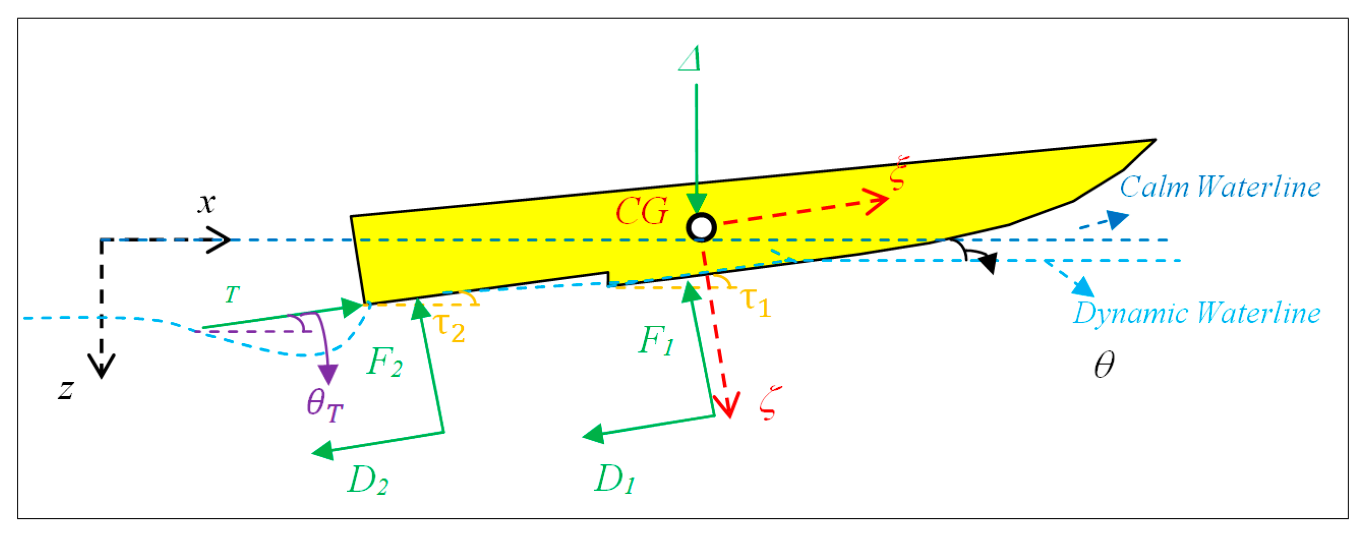
2. Mathematical Model
- The speed, V, was assumed to be constant for all two planing surfaces. In reality, the speed of the water would decrease aft of each step due to disturbances from the hull and turbulence. This would implicate that the lift from the middle and aft planing surface would be slightly exaggerated. By applying the effects of the transom and the steps, the forces will be calculated with a more accurate value.
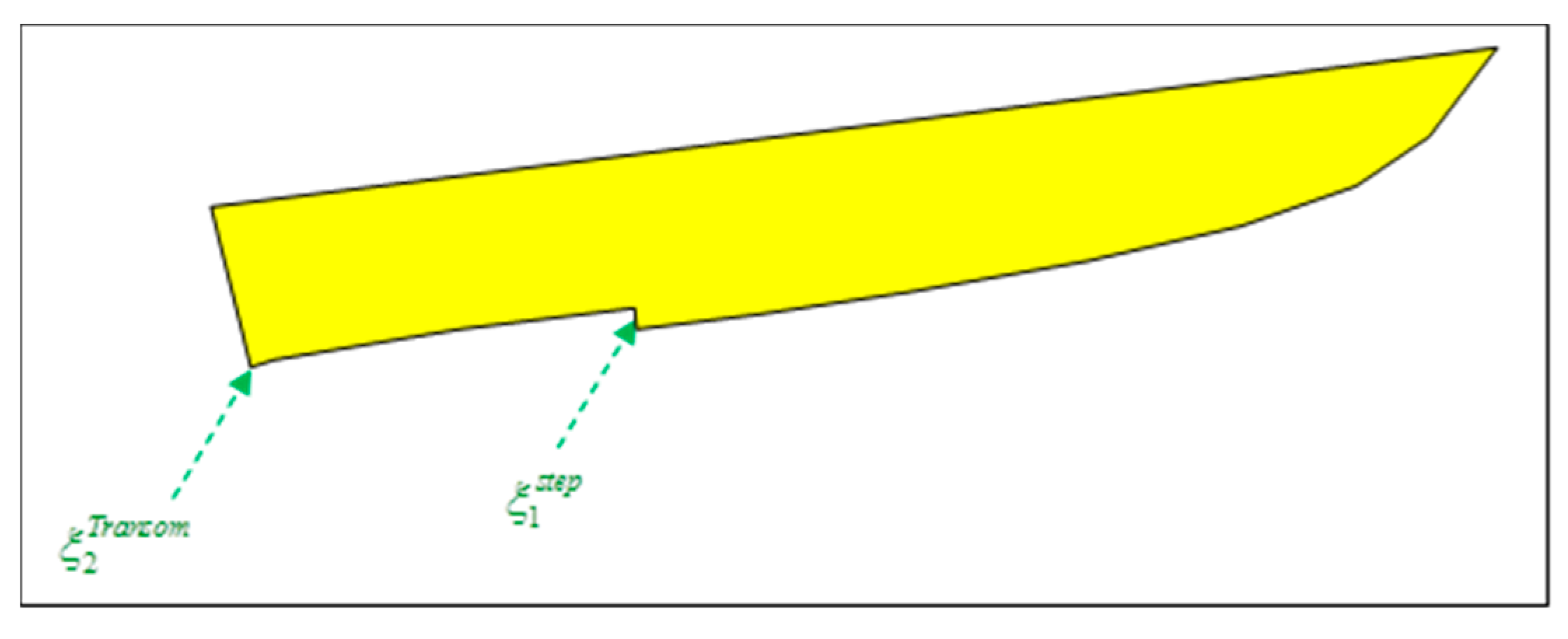
- The planing surfaces are assumed to have triangular shapes.
- The sweep-back of the steps is not included in the model.
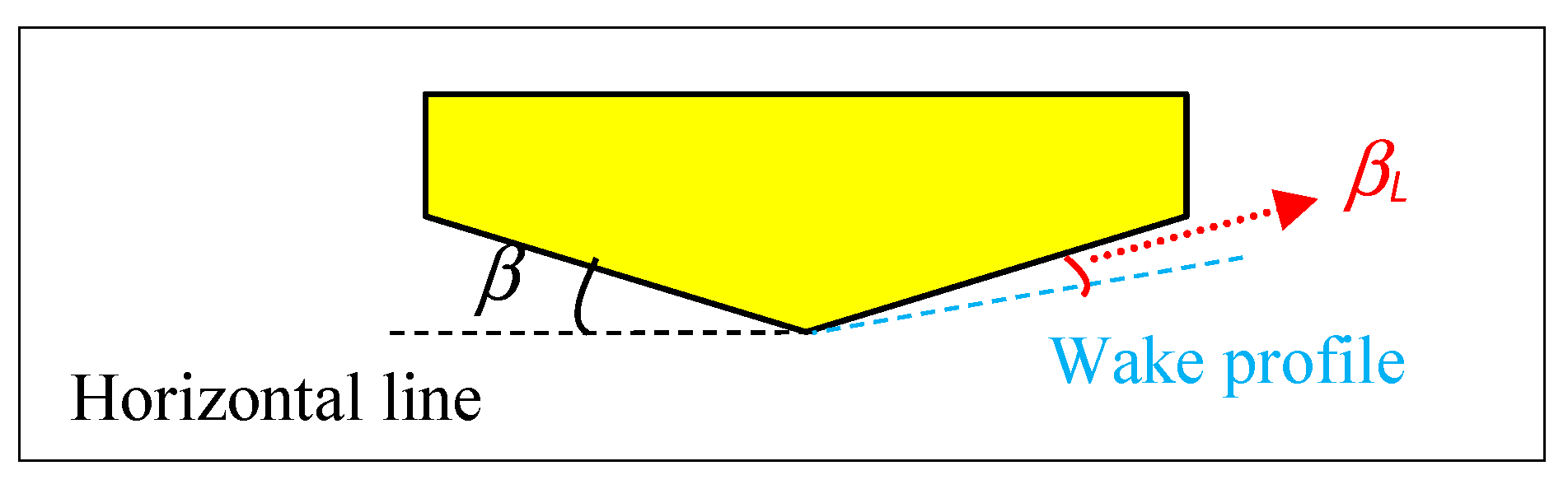
- The local deadrise angle has been assumed to be 2 degrees for each planing surface. This value depends on the ventilation length and has effects on the trim and resistance of the vessel because it affects the lift coefficients.
- The local trim angle, , has also been assumed to be 2 degrees. This value is measured using the slope of the planing surface in relation to the horizon, which has a straightforward relationship with step height.
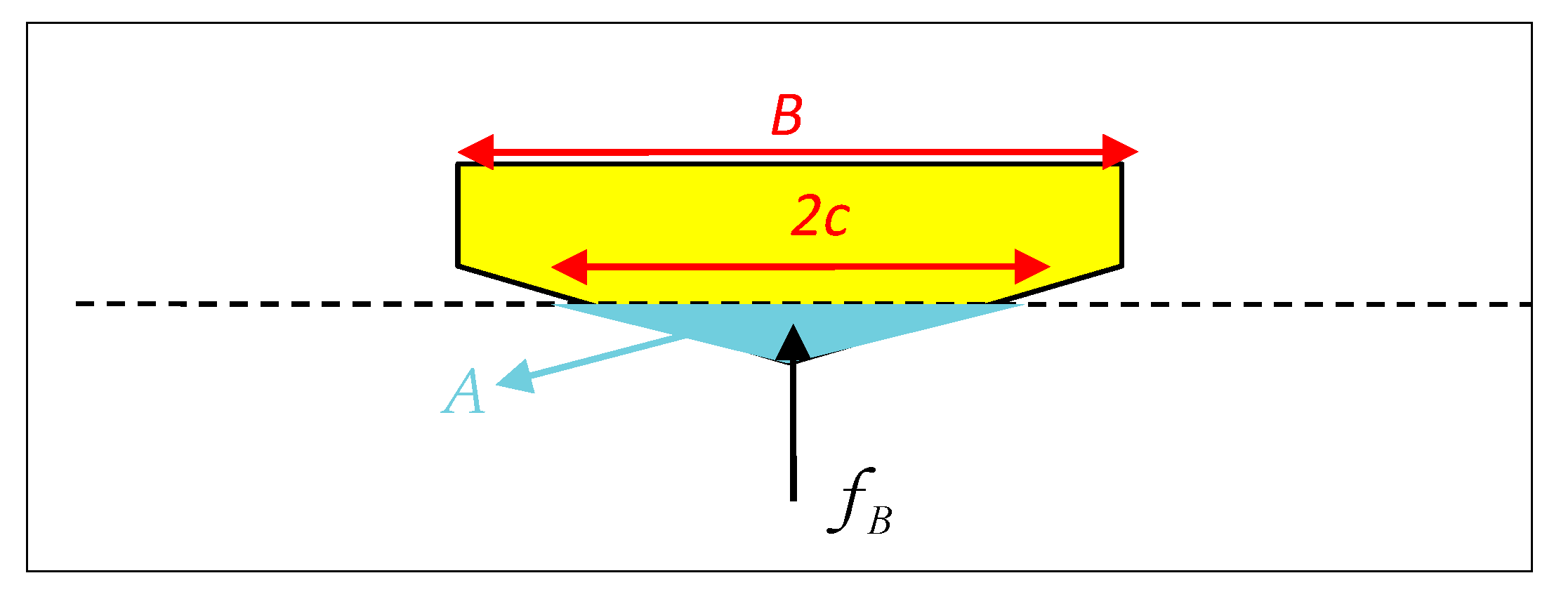
2.1. Two Dimensional Forces
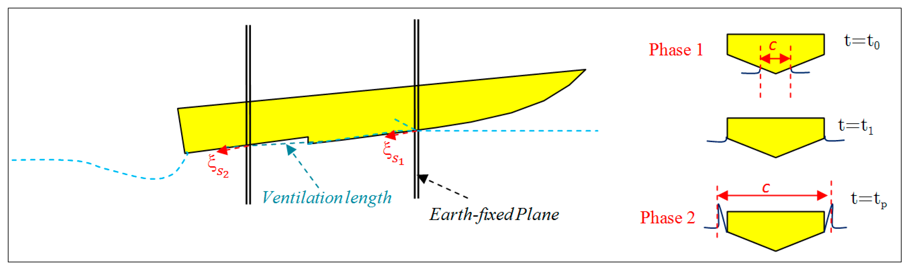
2.2. Phase 1—The Dry-Chine Condition
2.3. Phase 2—The Wet-Chine Condition
2.4. Three Dimensional Forces
2.5. Frictional Forces
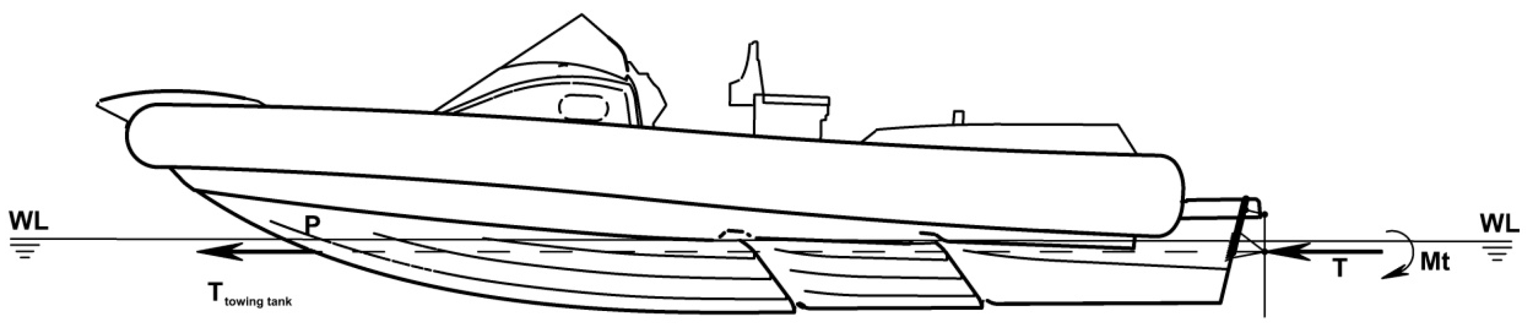
2.6. Resistance and Thrust
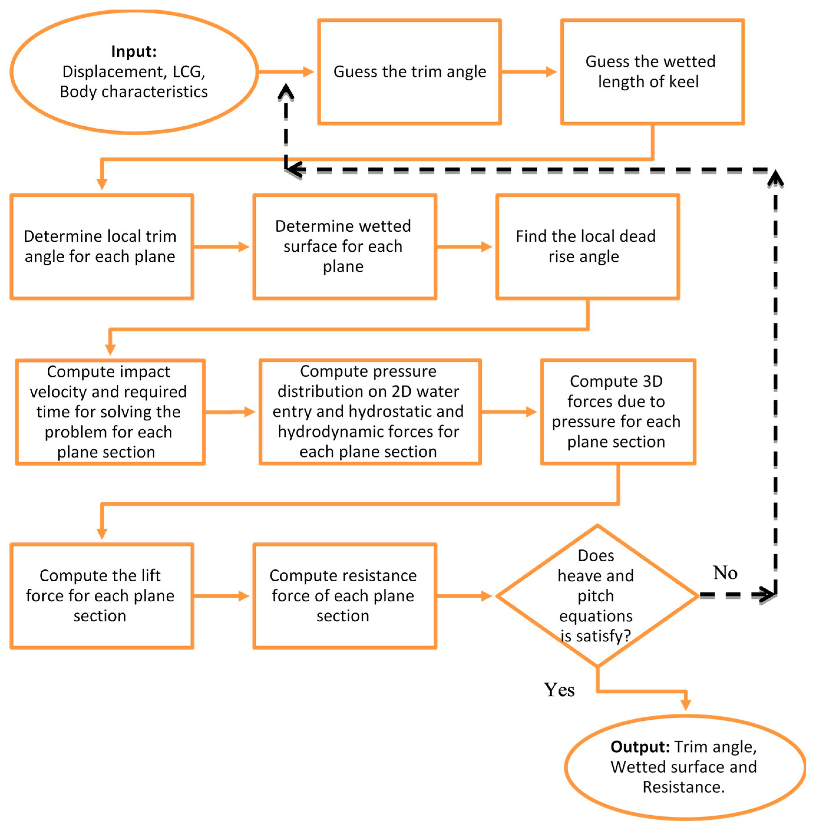
2.7. Computational Procedure
3. Validation and Results
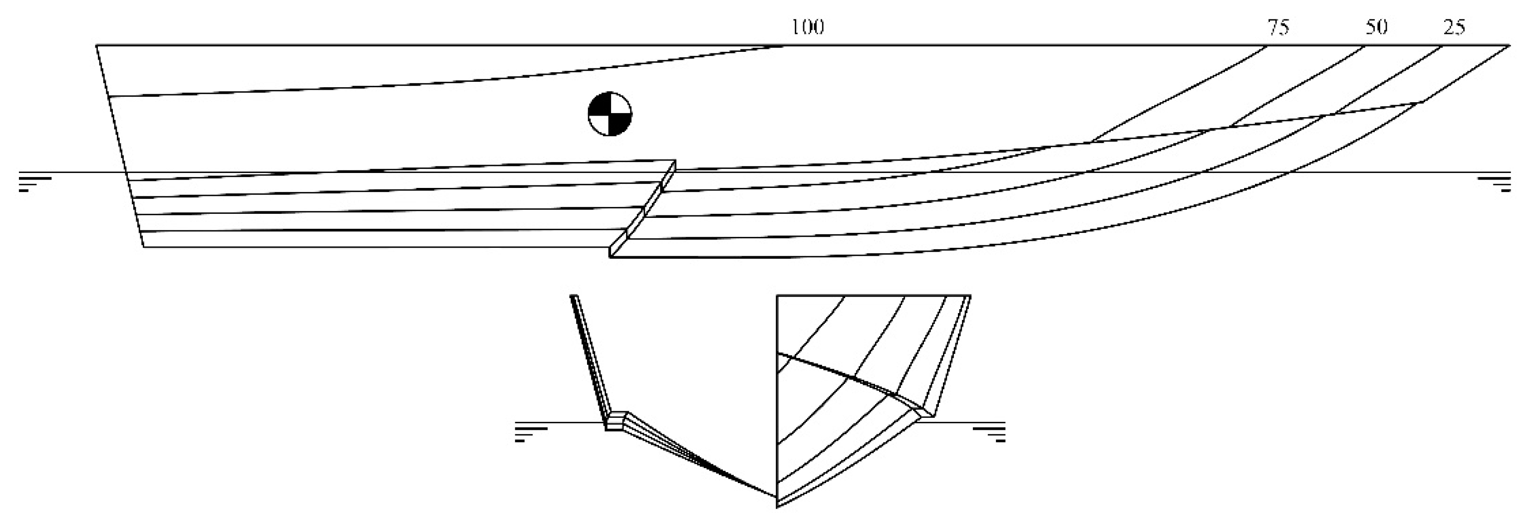
3.1. Model Tested and Experimental Details
3.2. Towing Tank vs. 2D + T Method Results
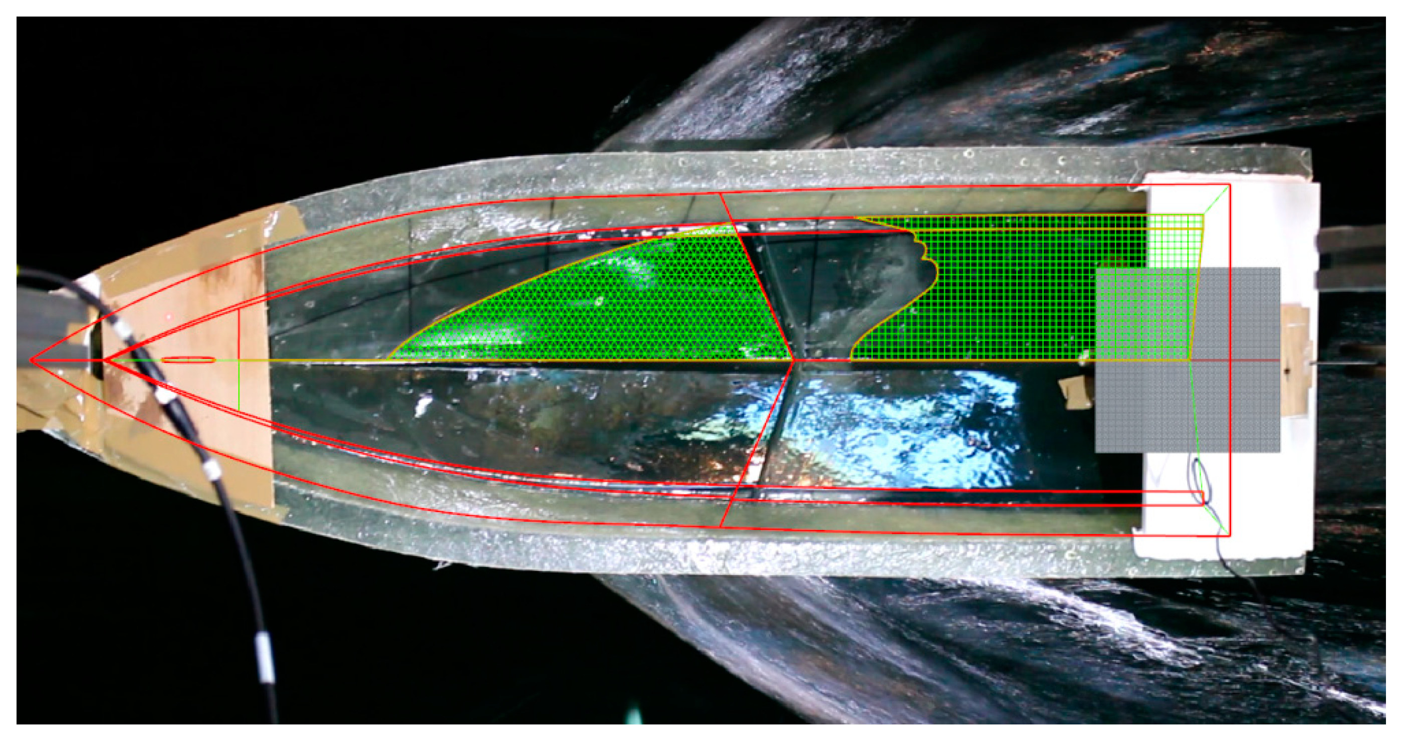
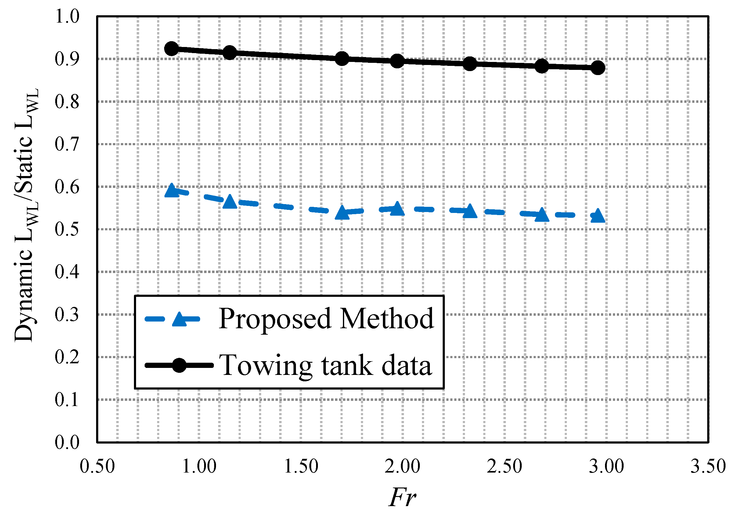
3.3. Wetted Surfaces and Wetted Length Analysis
4. Conclusions
Author Contributions
Funding
Conflicts of Interest
Nomenclature
| Boat Characteristics | |
| B | Beam of the boat (m) |
| Cfi | Frictional coefficient of the ith body |
| Froude number | |
| Beam Froude number | |
| Height of step (m) | |
| L | Length of the boat (m) |
| Chine wetted length of the ith body (m) | |
| LCG | Longitudinal Center of Gravity (m) |
| Wetted length of body ith body (m) | |
| Rni | Reynolds Number of the ith body |
| Wetted area of the ith body | |
| V | Forward moving velocity of the boat (m s‒1) |
| αi | stagnation line angle of the ith body |
| βi | Deadrise angle of the boat |
| Local deadrise angle of the boat of the ith body | |
| Δ | Weight of boat (N) |
| λi | Mean wetted length of the ith body |
| τi | Local trim angle of the ith body |
| θ | Dynamic trim angle of the hull |
| Distance | |
| anon | Non-dimensional distance at which transom reduction appears |
| Distance of step from the transom (m) | |
| Dry length of step from the transom | |
| x, y, z | Longitudinal (positive forward), transverse (positive starboard), and vertical distances (positive downward) from CG (Oxyz) (m) |
| ξ, η, ζ | Longitudinal (positive forward), transverse (positive starboard), and vertical distances (positive downward) (m) |
| ξi′ | Distance of section from the step or transom just located behind the section (m) |
| Distance of section from intersection of the keel and calm water of the ith body (m) | |
| Force and Moments | |
| Df | Frictional drag on pressure area (N) |
| Fi | Pressure force on ith body (N) |
| Drag acting on the spray area (N) | |
| R | Total resistance of the vessel |
| frictional drag of Whisker spray of the ith body | |
| Subscript x | Force component in surge direction (N) |
| Subscript z | Force component in heave direction (N) |
| Subscript θ | Force component in pitch direction (N) |
| Physical Parameters | |
| g | Gravitational constant |
| Pi | Pressure of the ith body (Pa) |
| ρ | Fluid density (kg m−3) |
| Sectional Parameters Related to 2.5D Theory | |
| Ai | Submerged area of the ith body (N m−1) |
| ci | Half beam of spray in transverse plane (m) |
| Time derivation of c (m s−2) | |
| Transom reduction at the section of the ith body (N m−1) | |
| Hydrodynamic force of each section of the ith body (N m−1) | |
| Hydrostatic force of each section of the ith body (N m−1) | |
| l | Distance from wedge apex in the direction of wedge wall (m) |
| t | Time |
| Chine wetting time of the ith body (s) | |
| Solution time for water entry problem of the ith body | |
| wi | Impact velocity of the ith body |
| yi | Lateral distance from wedge apex of the ith body |
| Subscript H | component in horizontal direction |
| Subscript V | component in vertical direction |
References
- Taunton, D.J.; Hudson, D.A.; Shenoi, R.A. Characteristics of a Series of High-speed Hard Chine Planing Hulls Part 1: Performance in Calm Water. Int. J. Small Craft Technol. 2010, 152, B55–B75. [Google Scholar]
- Lee, E.; Pavkov, M.; Mccue Weil, W. The Systematic Variation of Step Configuration and Displacement for a Double-Step Planing Craft. J. Ship Prod. Des. 2014, 30, 89–97. [Google Scholar] [CrossRef]
- De Marco, A.; Mancini, S.; Miranda, S.; Vitiello, L.; Scognamiglio, R. Experimental and numerical hydrodynamic analysis of a stepped planing hull. Appl. Ocean Res. 2017, 64, 135–154. [Google Scholar] [CrossRef]
- Savitsky, D. Hydrodynamic Design of Planing Hull. Mar. Technol. 1964, 1, 71–95. [Google Scholar]
- Dashtimanesh, A.; Tavakoli, S.; Sahoo, P. A simplified method to calculate trim and resistance of a two-stepped planing hull. Ships Offshore Struct. 2017, 12 (Suppl. 1), S317–S329. [Google Scholar] [CrossRef]
- Niazmand Bilandi, R.; Dashtimanesh, A.; Tavakoli, S. Development of a 2D + T theory for performance prediction of double-stepped planing hulls in calm water. J. Eng. Mar. Environ. 2018. [Google Scholar] [CrossRef]
- Di Caterino, F.; Niazmand Bilandi, R.; Mancini, S.; Dashtimanesh, A.; De Carlini, M. Numerical Way for a Stepped Planing Hull Design and Optimization. In Proceedings of the 19th International Conference on Ship & Maritime Research, Trieste, Italy, 20–22 June 2018. [Google Scholar]
- Dashtimanesh, A.; Esfandiari, A.; Mancini, S. Performance Prediction of Two-Stepped Planing Hulls Using Morphing Mesh Approach. J. Ship Prod. Des. 2018, 1–13. [Google Scholar] [CrossRef]
- Von Karman, T. The Impact on Seaplane Floats during Landing (National Advisory Committee for Aeronautics No. 321); NACA Translation: Washington, DC, USA, 1929. [Google Scholar]
- Wagner, H. Phenomena Associated with Impacts and Sliding on Liquid Surfaces; NACA Translation: Washington, DC, USA, 1932. [Google Scholar]
- Svahn, D. Performance Prediction of Hulls with Transverse Steps. Master’s Thesis, Marina System Centre for Naval Architecture, KTH University, Stockholm, Sweden, 2009. [Google Scholar]
- Savitsky, D.; Morabito, M. Surface wave contours associated with the fore body wake of stepped planing hulls. Mar. Technol. 2010, 47, 1–16. [Google Scholar]
- Danielsson, J.; Strømquist, J. Conceptual Design of a High Speed Superyacht Tender Hull Form Analysis and Structural Optimization. Master’s Thesis, Marina System Centre for Naval Architecture, KTH University, Stockholm, Sweden, 2012. [Google Scholar]
- Zarnick, E. A Nonlinear Mathematical Model of Motions of a Planing Boat in Regular Waves Technical Report; Report No. DTNSRDC-78/032; Bethesda, David W Taylor Naval Ship Research and Development Center: Rockville, MD, USA, 1978. [Google Scholar]
- Ghadimi, P.; Dashtimanesh, A.; Djeddi, S.R.; Maghrebi, Y.F. Development of a mathematical model for simultaneous heave, pitch and roll motions of planing vessel in regular waves. Int. J. Sci. World 2013, 1, 44–56. [Google Scholar] [CrossRef]
- Ghadimi, P.; Dashtimanesh, A.; Faghfoor Maghrebi, Y. Initiating a mathematical model for prediction of 6-DOF motion of planing crafts in regular waves. Int. J. Eng. Math. 2013, 2013, 853793. [Google Scholar] [CrossRef]
- Ghadimi, P.; Tavakoli, S.; FeiziChekab, M.A.; Dashtimanesh, A. Introducing a Particular Mathematical Model for Predicting the Resistance and Performance of Prismatic Planing Hulls in Calm Water by Means of Total Pressure Distribution. J. Nav. Arch. Mar. Eng. 2015, 12, 73–94. [Google Scholar] [CrossRef]
- Ghadimi, P.; Tavakoli, S.; Dashtimanesh, A. Coupled heave and pitch motions of planing hulls at non-zero heel angle. Appl. Ocean Res. 2016, 59, 286–303. [Google Scholar] [CrossRef]
- Ghadimi, P.; Tavakoli, S.; Dashtimanesh, A. An analytical procedure for time domain simulation of roll motion of the warped planing hulls. Proc. Inst. Mech. Eng. Part M J. Eng. Mar. Environ. 2016, 230, 600–615. [Google Scholar] [CrossRef]
- Tavakoli, S.; Ghadimi, P.; Dashtimanesh, A.; Sahoo, P. Determination of hydrodynamic coefficients in roll motion of high-speed planing hulls. In Proceedings of the 13th International Conference on Fast Sea Transportation, Washington, DC, USA, 1–4 September 2015. [Google Scholar]
- Tavakoli, S.; Ghadimi, P.; Dashtimanesh, A. A nonlinear mathematical model for coupled heave, pitch, and roll motions of a high-speed planing hull. J. Eng. Math. 2017, 104, 157–194. [Google Scholar] [CrossRef]
- Tavakoli, S.; Ghadimi, P.; Sahoo, P.K.; Dashtimanesh, A. A hybrid empirical–analytical model for predicting the roll motion of prismatic planing hulls. Proc. Inst. Mech. Eng. Part M J. Eng. Mar. Environ. 2018, 232, 155–175. [Google Scholar] [CrossRef]
- Tavakoli, S.; Dashtimanesh, A.; Sahoo, P.K. An oblique 2D + T approach for hydrodynamic modeling of yawed planing boats in calm water. J. Ship Prod. Des. 2017. [Google Scholar] [CrossRef]
- Algarin, R.; Tascon, O. Hydrodynamic modeling of planing boats with asymmetry and steady condition. In Proceedings of the 9th International Conference on High Performance Marine Vehicles (HIPER 11), Naples, Italy, 25–27 May 2011. [Google Scholar]
- Garme, K. Improved time domain simulation of planing hulls in waves by correction of the near-transom lift. Int. Shipbuild. Prog. 2005, 52, 201–230. [Google Scholar]
- The International Towing Tank Conference. ITTC Recommended Procedures and Guidelines: Ship Models; ITTC: Rio de Janeiro, Brazil, 2011. [Google Scholar]
- Vitiello, L.; Miranda, S. Propulsive performance analysis of a stepped hull by model test results and sea trial data. In Proceedings of the 10th Symposium on High Speed Marine Vehicles (HSMV 2014), Naples, Italy, 15–17 October 2014; ISBN 9788890611216. [Google Scholar]
- De Luca, F.; Mancini, S.; Pensa, C.; Miranda, S. An Extended Verification and Validation Study of CFD Simulations for Planing Hulls. J. Ship Res. 2016, 60, 101–118. [Google Scholar] [CrossRef]
- Mancini, S.; De Luca, F.; Ramolini, A. Towards CFD guidelines for planing hull simulations based on the Naples Systematic Series. In Proceedings of the Computational Methods in Marine Engineering VII (Marine 2017), Nantes, France, 15–17 May 2017. [Google Scholar]


| Description | |
|---|---|
| Length overall: LOA (m) | 0.935 |
| Breadth max: BMAX (m) | 0.335 |
| Deadrise angle at transom (°) | 23 |
| Step height (mm) | 6 |
| Displacement (N) | 30.705 |
| LCG (%L) | 33 |
| Model scale | 1:10 |
| Fr | RTM/Δ | Trim | WS/∇2/3 | ||||||
|---|---|---|---|---|---|---|---|---|---|
| Exp. | 2D + T Approach | Error | Exp. | 2D + T Approach | Error | Exp. | 2D + T Approach | Error | |
| (-) | (-) | (%) | (deg) | (deg) | (%) | (-) | (-) | (%) | |
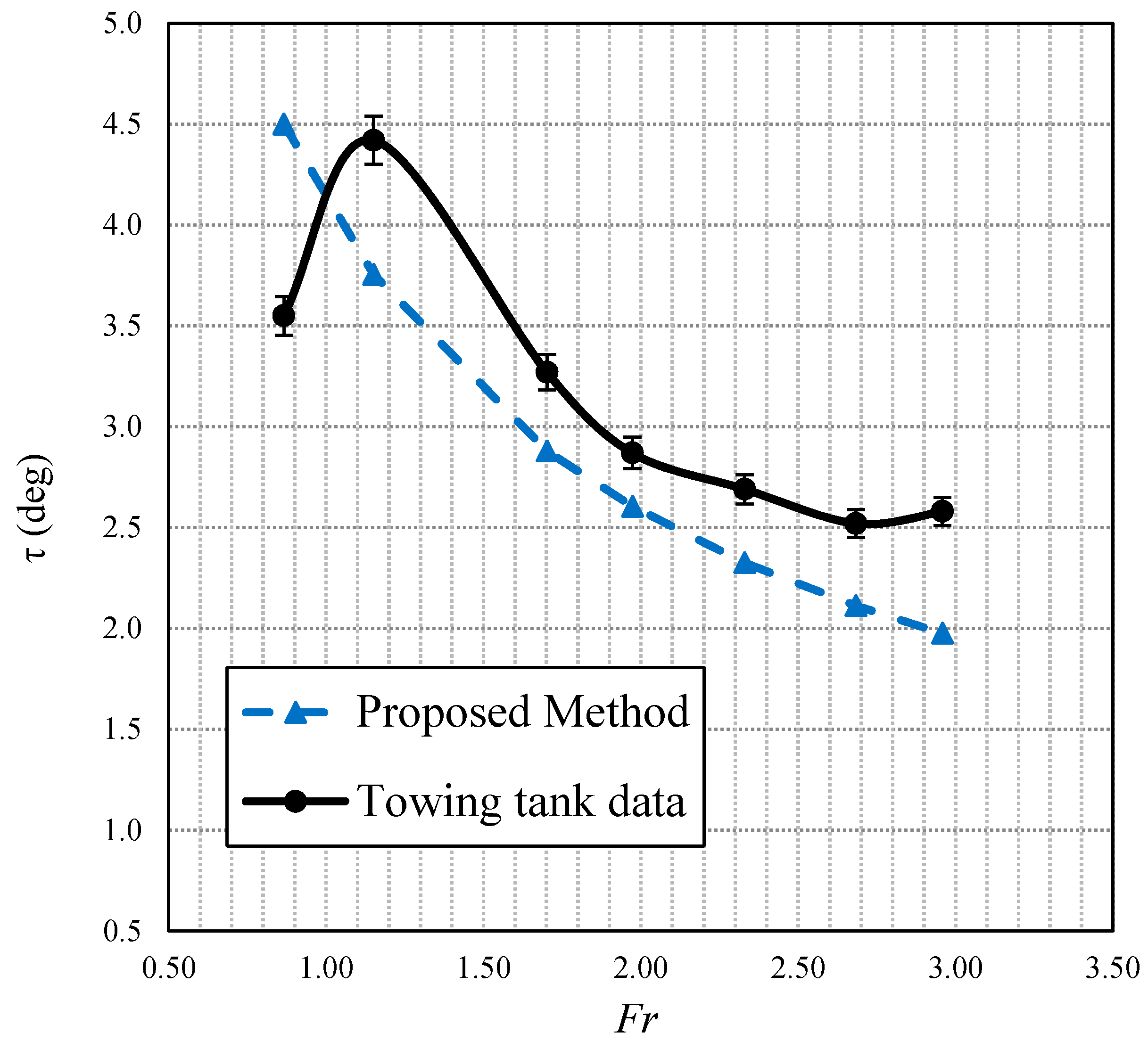
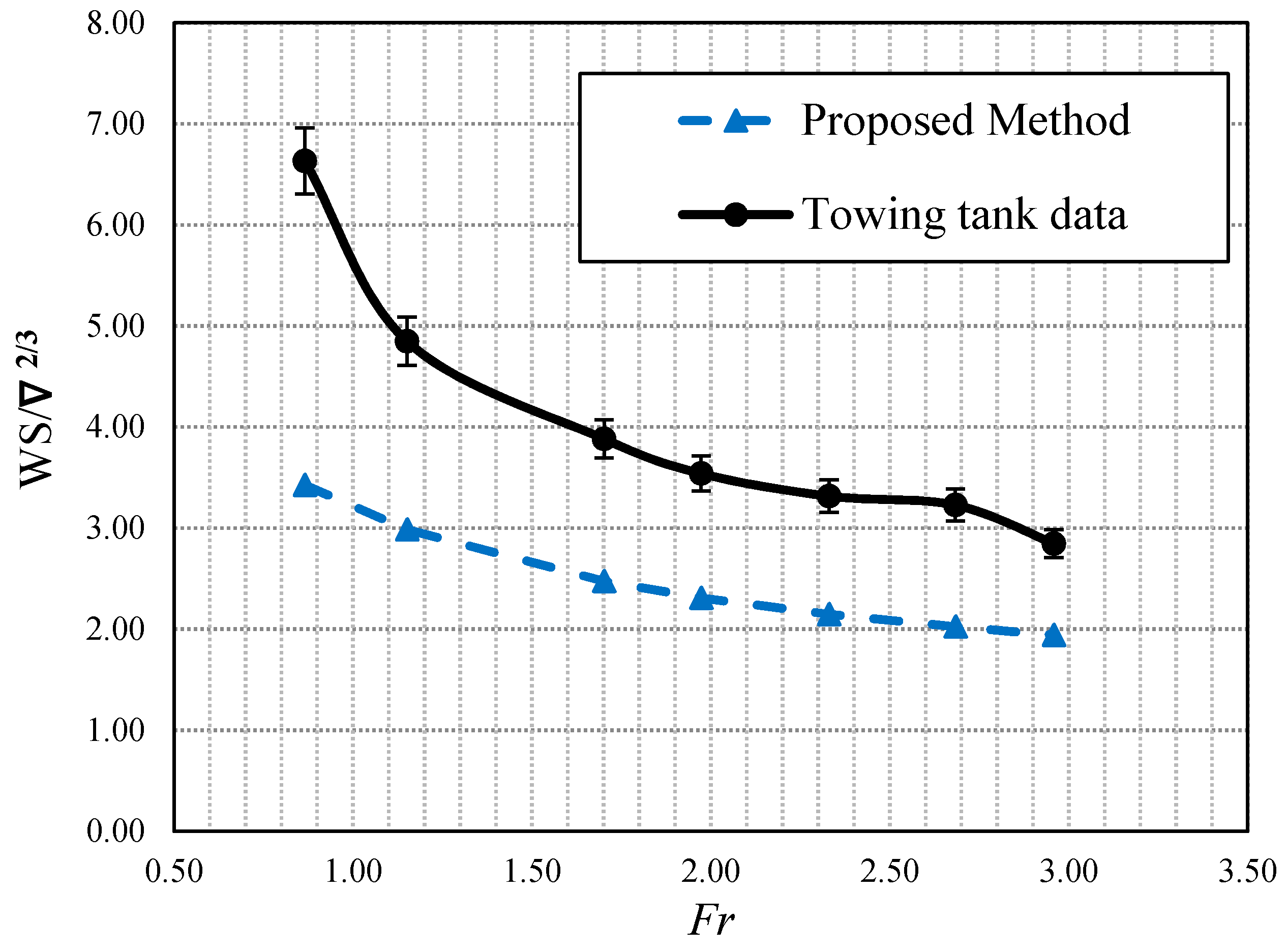
| 0.866 | 0.182 | 0.181 | 0.2 | 3.550 | 4.500 | −26.8 | 6.63 | 3.43 | 48.3 |
| 1.151 | 0.208 | 0.201 | 3.1 | 4.420 | 3.755 | 15.0 | 4.85 | 2.99 | 38.4 |
| 1.702 | 0.261 | 0.255 | 2.3 | 3.270 | 2.880 | 11.9 | 3.88 | 2.47 | 36.2 |
| 1.973 | 0.318 | 0.288 | 9.5 | 2.870 | 2.605 | 9.2 | 3.54 | 2.31 | 34.7 |
| 2.330 | 0.415 | 0.336 | 19.1 | 2.690 | 2.326 | 13.5 | 3.32 | 2.15 | 35.2 |
| 2.683 | 0.501 | 0.389 | 22.3 | 2.520 | 2.113 | 16.2 | 3.23 | 2.03 | 37.3 |
| 2.958 | 0.566 | 0.434 | 23.5 | 2.580 | 1.976 | 23.4 | 2.85 | 1.94 | 31.7 |
| Fr | RTM/Δ | Trim | WS/∇2/3 | |||
|---|---|---|---|---|---|---|
| EXP–CFD | EXP–2D + T | EXP–CFD | EXP–2D + T | EXP–CFD | EXP–2D + T | |
| (%) | (%) | (%) | (%) | (%) | (%) | |
| 0.866 | 5.46 | 0.20 | −9.01 | −26.76 | −8.14 | 48.33 |
| 1.702 | −1.90 | 2.32 | −1.22 | 11.93 | −31.20 | 36.24 |
| 2.330 | 9.33 | 19.07 | −0.37 | 13.53 | −31.15 | 35.19 |
| 2.958 | 5.26 | 23.46 | −3.10 | 23.41 | −36.13 | 31.71 |
| Fr | Analytical Wetted Surface | Experimental Wetted Surface |
|---|---|---|
| 0.866 |  |  |
| 1.151 |  |  |
| 1.702 |  |  |
| 1.973 |  |  |
| 2.330 |  |  |
| 2.683 |  |  |
| 2.958 |  |  |
© 2018 by the authors. Licensee MDPI, Basel, Switzerland. This article is an open access article distributed under the terms and conditions of the Creative Commons Attribution (CC BY) license (http://creativecommons.org/licenses/by/4.0/).
Share and Cite
Bilandi, R.N.; Mancini, S.; Vitiello, L.; Miranda, S.; De Carlini, M. A Validation of Symmetric 2D + T Model Based on Single-Stepped Planing Hull Towing Tank Tests. J. Mar. Sci. Eng. 2018, 6, 136. https://doi.org/10.3390/jmse6040136
Bilandi RN, Mancini S, Vitiello L, Miranda S, De Carlini M. A Validation of Symmetric 2D + T Model Based on Single-Stepped Planing Hull Towing Tank Tests. Journal of Marine Science and Engineering. 2018; 6(4):136. https://doi.org/10.3390/jmse6040136
Chicago/Turabian StyleBilandi, Rasul Niazmand, Simone Mancini, Luigi Vitiello, Salvatore Miranda, and Maria De Carlini. 2018. "A Validation of Symmetric 2D + T Model Based on Single-Stepped Planing Hull Towing Tank Tests" Journal of Marine Science and Engineering 6, no. 4: 136. https://doi.org/10.3390/jmse6040136