Investigating the Pre-Damaged PZT Sensors under Impact Traction


1
Mechanical Engineering Department, University of Tabriz, Tabriz 51666-14766, Iran
2
Department of Design and Mathematics, University of the West of England, Bristol BS16 1QY, UK
3
Department of Industrial Engineering, University of Bologna, Viale Risorgimento 2, 40136 Bologna, Italy
4
Institute of Materials and Manufacturing, College of Engineering, Design and Physical Sciences, Brunel University London, UB8 3PN London, UK
*
Author to whom correspondence should be addressed.
J. Mar. Sci. Eng. 2018, 6(4), 142; https://doi.org/10.3390/jmse6040142
Submission received: 2 October 2018
/
Revised: 11 November 2018
/
Accepted: 11 November 2018
/
Published: 19 November 2018
(This article belongs to the Special Issue Engineering Mathematics in Ship Design)
Abstract
:Ships are usually under vibration, impact, and other kinds of static and dynamic loads. These loads arise from water flow across the hull or surfaces, the propeller cavitation, and so on. For optimal design purposes and reliable performance, experimental measurements are necessary. These sensors are often used under or near the water, working conditions that improve the risk of sensor damage. This paper aims at investigating, by the use of finite elements, the behavior of damaged piezoelectric sensors under traction and impact loads. The numerical method was calibrated using results available in the literature regarding piezoelectric and elastic plates with a central crack. After calibration, the simulation was used on two types of Lead-Zirconium-Titanium oxide (PZT) sandwich panel structures reinforced by aluminum skins. The results proved that the damage size and impact energy are important factors affecting the response of piezoelectric sensors; therefore, special attention might be considered when using these sensors for marine applications.
1. Introduction
Lead-Zirconium-Titanium oxide (PZT) is a piezoelectric ceramic often used for actuator and sensor applications. PZTs have been widely used in underwater transducers and sensors. PZTs have sensory application in marine and other engineering application industries [1,2,3,4,5,6]. However, PZTs are very brittle and susceptible to damage during service [7]. Therefore, it is important to understand the fracture behavior of these materials with the existence of damage, and also in comparison with other conventional techniques [8,9,10]. As PZT ceramics are brittle and sensitive, they are usually made in sandwich panel (or composite) forms. There are many studies about the fracture behavior of the piezoelectric composites. In References [11,12,13,14,15], antiplane strain of damaged PZT strips and composites were investigated. Recently, there have been some applicable analytical solutions for the fracture behavior in PZTs. For example, Shindo et al. [16] analyzed an infinite orthotropic PZT plate with a Griffith crack under shear impact loading. Chen and Meguid [17] studied a cracked piezoelectric strip influenced by electromechanical loading. Wanga and Noda [18] studied a piezoelectric layer bonded to the surface of an elastic structure with a crack under transient load in a piezoelectric layer bonded to a dissimilar elastic layer under transient load. Ueda [19] studied the dynamic response of a central cracked piezoelectric composite plate with impact loading. Garcıa-Sanchez et al. [20,21] used a Boundary Element Method (BEM) for analyses of the transient response of cracked linear piezoelectric solids. Fotouhi et al. used Finite Element Modelling (FEM) to investigate the thickness and material properties of piezoelectric layer influence on the fracture response of PZT composite. The results proved that the stress intensity factor is influenced by these parameters [22].
2. Materials and Methods
2.1. Aim and Scope
To improve the situational awareness, obstacle avoidance of marine vehicles and energy harvesting, thin-film piezoelectric pressure sensors are used widely for underwater sensing. Most of these piezoelectric sensors/actuators are manufactured with a sandwich structure [23]. This study aims to investigate the dynamic behavior of a sandwich piezoelectric panel, piezoelectric layers between two Aluminum skins, with a central crack under impact traction and dynamic stress intensity factor (DSIF) near the tip of the crack. The research analyzes, in particular, the effect of the pre-existing crack on the response of a piezoelectric layered composite plate with finite dimensions. The results are useful to (a) develop an optimum sensor design; (b) consider the crack effects on the piezoelectric behavior, and (c) verify if PZT sensors are suitable or not for the use.
2.2. Validation
The results were obtained using numerical simulations. At first, the computational model, developed in accordance with previous researches [22,24,25,26], was checked using two samples from literature: a pure piezoelectric plate of BaTiO3 [27], and a pure elastic sample [28,29] with a crack. A brief characteristic of these cases is illustrated in Figure 1. The numerical results were compared with the available information, and an acceptable matching was observed (Table 1). The error percentage (Error (%)) is calculated by 100*((Our simulation value—Previous study’s value)/Previous study’s value)). Figure 2 illustrates the efficiency of the simulation method.
After the validation phase, the procedure was applied to simulate the finite PZT composite plates illustrated in Figure 3. Numerical results for the DSIF were observed for several piezoelectric layered composite plates. The main objective of this paper is to investigate the effect of impact energy level and a pre-existing crack length on fracture response of a PZT composite plate.
2.3. Simulation of the Piezoelectric Composite Plate
In this article, PZT composite contains a PZT core layer of 2h1 thickness that interleaved between two elastic layers of thickness h2–h1 with a crack in the center as shown in Figure 3. These piezoelectric materials have a wide application in real marine structure as sensors/actuators. The crack length is 2c [19]. PZT composite is subjected to an impact traction of the form (according to Figure 3), where is 2 . The width of the PZT composite is defined by h = 20 mm [29]. The h1 is equal to 5 mm and the and c changed in the simulation according to the aims. The needed materials’ properties are in Table 2. The Poisson’s ratio of aluminum is 0.28. In addition, all of these needed parameters are listed in Table 3.
The size and property of the piezoelectric materials depend on their application. This case study assumes a damaged piezoelectric sensor in marine, ocean, and other underwater structures. To examine the effect of damaged sensors, the FEM is used. Two samples are considered: Aluminum/PZT-4/Aluminum and Aluminum/PZT-5H/Aluminum. The piezoelectric plate was simulated with a shell planer part as an anisotropic plate with properties listed in Table 2. A uniform traction load with a defined amplitude (according to Figure 3) was applied on the piezoelectric laminate. Free edge boundary condition was used for the plate’s boundaries to simulate the real-world application of the sensors. Standard, linear, and plane strain mesh type were used for the modeling. Sweep quad-dominated mesh was utilized for the crack tips, and free quad-dominated mesh with medium mesh size was used for the other regions. The influence of two variations, i.e., the crack length and impact energy levels, on DSIF under impact loadings in the PZT composite plates, are reported in Table 3.
3. Results
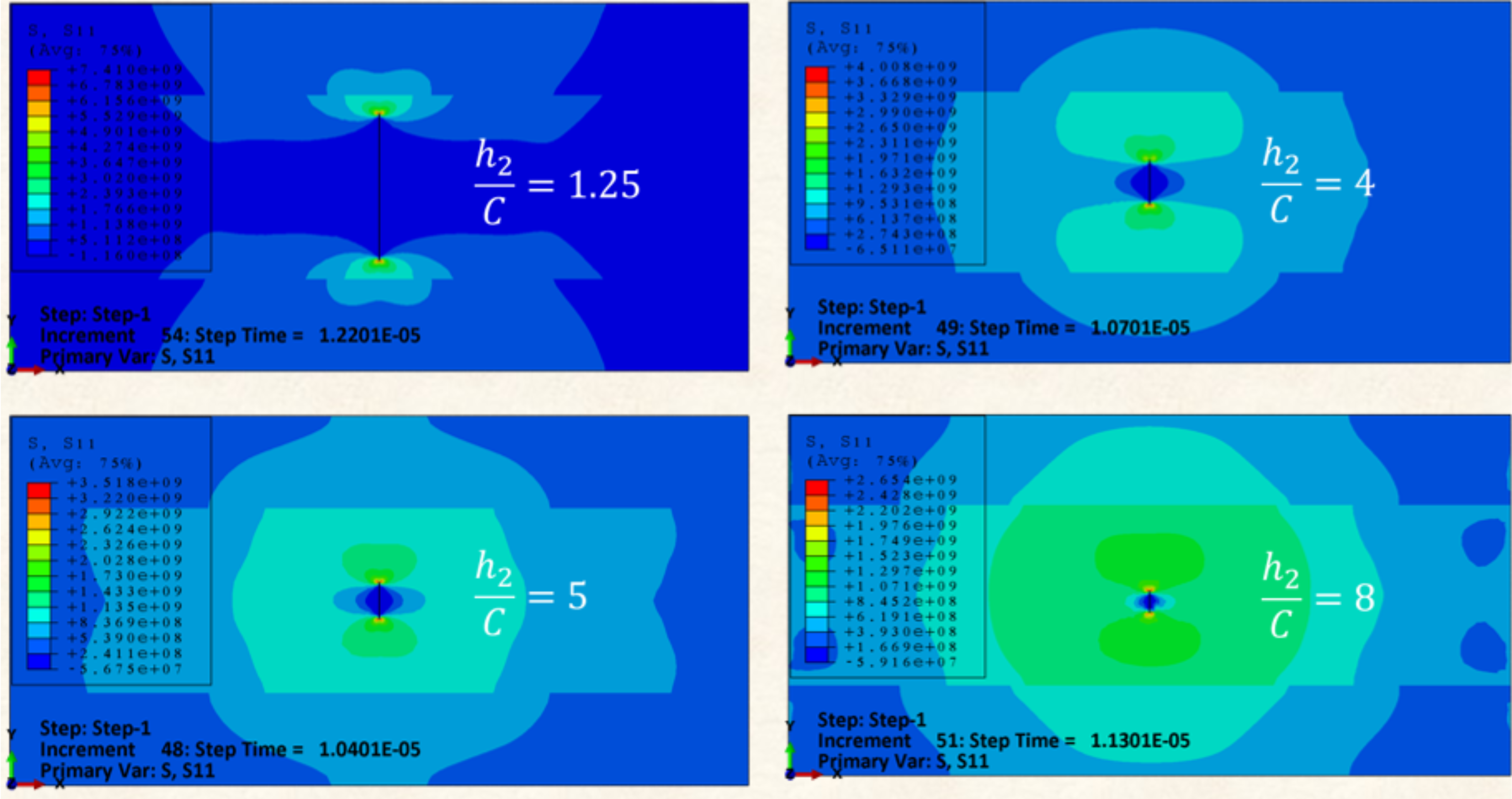
3.1. The Crack Length of the Piezoelectric Composite Plate
3.2. The Impact Energy Effect on the Piezoelectric Composite Plate
Piezoelectric sensors are used for marine applications for detection of the applied loads, stresses etc. These sensors usually are in different loads, such as impact, with different energy levels. To investigate the effect of impact energy level on stress distribution and DSIF, the piezoelectric composites with constant ratios of piezoelectric layer thickness (h1) to crack length (c) and the composite thickness (h2) to the piezoelectric layer thickness (h1) equal 2 (i.e., h2/h1 = 2), were subjected to different loading conditions (100, 200, 300, and 400 MPa) and the results are shown in Figure 8. Some of the results show negative DSIF. It observed that when the crack is oriented vertically or almost vertically, the DSIF becomes negative, indicating that the crack closes because of compressive loading normal to the crack surface [30] and it is a good topic to investigate widely in the related study.
4. Discussion
The DSIF and Tmax increase by increasing the crack length. There are some fluctuations for higher numbers of h1/c, but in reality, these situations are rarely observable and are not real case studies. It is also observed that by increasing the impact level the DSIF increases significantly, but there is almost no change in the Tmax. This is in accordance with a usual fracture response of a laminated composite plate under impact or indentation load, where there is no difference between the rise time of the maximum load under different impact energy levels [19]. So, there is a good agreement between the fracture response of the investigated piezoelectric layered composites in this paper and conventional laminated composite plates with different stacking sequences, despite the multi-functionality of the piezoelectric composites.
5. Conclusions
This study aimed to investigate the effect of an existed damage in laminated PZT sensors that are often used under or near the water working conditions, i.e., the marine industry. For this reason, the fracture response of a PZT composite sensor with a central crack was considered under impact traction, which is a typical loading condition in the marine industry. The fracture response of the PZT composite sensor with a central crack, under impact traction, was considered. DSIF of the crack tip was analyzed. FEM was used to simulate the problem. The numerical results illustrated that DSIF and stress distribution of the PZT composite depends on the crack length and impact energy. The rise time of the stress intensity factor and stress distribution pattern changes with crack length, but the level of impact energy does not affect the rise time (Tmax). It can be concluded that the proposed modeling procedure was very useful for the understanding of the dynamic behavior of piezoelectric materials with existent damage and can help to increase our knowledge for a better design and manufacturing of piezoelectric materials for engineering applications and more specifically marine industry.
Author Contributions
Conceptualization, S.F. and M.F.; methodology, M.F.; software, S.F. and A.P.; validation, M.F.; formal analysis, N.D.; investigation, S.F. and M.F.; resources, X.X.; data curation, A.P. and N.D.; writing-original draft preparation, S.F. and M.F.; writing-review and editing, S.F. and A.P.; supervision, N.D. and M.F.
Funding
This research received no external funding.
Acknowledgments
Special thanks to the Faculty of Environment and Technology, University of the West of England, for funding the researchers’ mobility at the University of Bologna.
Conflicts of Interest
The authors declared no potential conflict of interest with respect to the research, authorship, and/or publication of this article.
References
- Huidong, L.; Zhiqun, D.D.; Yong, Y.; Thomas, J.C. Design Parameters of a Miniaturized Piezoelectric Underwater Acoustic Transmitter. Sensors 2012, 12, 9098–9109. [Google Scholar] [CrossRef]
- Akdogan, E.K.; Allahverdi, M.; Safari, A. Piezoelectric composites for sensor and actuator applications. IEEE Trans. Ultrason. Ferroelectr. Freq. Control 2005, 52, 746–775. [Google Scholar] [CrossRef] [PubMed]
- Galassi, C.; Roncari, E.; Capiani, C.; Fabbri, G.; Piancastelli, A.; Peselli, M.; Silvano, F. Processing of Porous PZT Materials for Underwater Acoustics. Ferroelectrics 2002, 268, 42–57. [Google Scholar] [CrossRef]
- Fotouhi, M.; Saeedifar, M.; Yousefi, J.; Fotouhi, S. The application of an acoustic emission technique in the delamination of laminated composites. In Focus on Acoustic Emission Research; NOVA Publishers: Hauppauge, NY, USA, 2016. [Google Scholar]
- Fotouhi, M.; Najafabadi, M.A. Acoustic emission-based study to characterize the initiation of delamination in composite materials. J. Thermoplast. Compos. Mater. 2016, 29, 519–537. [Google Scholar] [CrossRef]
- Fotouhi, M.; Suwarta, P.; Jalalvand, M.; Czel, G.; Wisnom, M.R. Detection of fibre fracture and ply fragmentation in thin-ply UD carbon/glass hybrid laminates using acoustic emission. Compos. Part A Appl. Sci. Manuf. 2016, 86, 66–76. [Google Scholar] [CrossRef]
- Mamoru, M.; Yuta, E.; Mitsuhiro, O. Fatigue life of piezoelectric ceramics and evaluation of internal damage. Procedia Eng. 2010, 2, 291–297. [Google Scholar]
- Fragassa, C.; Minak, G. Measuring deformations in a rigid-hulled inflatable boat. Key Eng. Mater. 2017, 754, 295–298. [Google Scholar] [CrossRef]
- Heidary, H.; Sadri, M.; Karimi, N.Z.; Fragassa, C. Numerical Study of Plasticity Effects in Uniform Residual Stresses Measurement by Ring-Core Technique. J. Serb. Soc. Comput. Mech. 2017, 11, 17–26. [Google Scholar] [CrossRef]
- Zivkovic, I.; Pavlovic, A.; Fragassa, C.; Brugo, T. Influence of moisture absorption on the impact properties of flax, basalt and hybrid flax/basalt fiber reinforced green composites. Compos. Part B Eng. 2017, 111, 148–164. [Google Scholar] [CrossRef]
- Shindo, Y.; Narita, F.; Tanaka, K. Electroelastic intensification near anti-plane shear crack in orthotropic piezoelectric ceramic strip. Theor. Appl. Fract. Mech. 1996, 25, 65–71. [Google Scholar] [CrossRef]
- Shindo, Y.; Tanaka, K.; Narita, F. Singular Stress and electric fields of a piezoelectric ceramic strip with a finite crack under longitudinal shear. Acta Mech. 1997, 120, 31–45. [Google Scholar] [CrossRef]
- Shindo, Y.; Watanabe, K.; Narita, F. Electroelastic analysis of a piezoelectric ceramic strip with a central crack. Int. J. Eng. Sci. 2000, 38, 1–19. [Google Scholar] [CrossRef]
- Narita, F.; Shindo, Y. Layered piezoelectric medium with interface crack under anti-plane shear. Theor. Appl. Fract. Mech. 1998, 30, 119–126. [Google Scholar] [CrossRef]
- Narita, F.; Shindo, Y. The interface crack problem for bonded piezoelectric and orthotropic layers under antiplane shear loading. Int. J. Fract. 1999, 98, 87–102. [Google Scholar] [CrossRef]
- Shindo, Y.; Narita, F.; Ozawa, E. Impact response of a finite crack in an orthotropic piezoelectric ceramic. Acta Mech. 1999, 137, 99–107. [Google Scholar] [CrossRef]
- Chen, Z.T.; Meguid, S.A. The transient response of a piezoelectric strip with a vertical crack under electromechanical impact load. Int. J. Solids Struct. 2000, 37, 6051–6062. [Google Scholar] [CrossRef]
- Wang, B.L.; Noda, N.A. Crack in a piezoelectric layer bonded to a dissimilar elastic layer under transient load. Arch. Appl. Mech. 2001, 71, 487–494. [Google Scholar] [CrossRef]
- Ueda, S. Impact response of a piezoelectric layered composite plate with a crack. Theor. Appl. Fract. Mech. 2002, 38, 221–242. [Google Scholar] [CrossRef]
- Garcıa-Sanchez, F.; Zhang, Ch.; Sladek, J.; Sladek, V. 2D transient dynamic crack analysis in piezoelectric solids by BEM. Comput. Mater. Sci. 2007, 39, 179–186. [Google Scholar] [CrossRef]
- Garcıa-Sanchez, F.; Zhang, C.; Saez, A. 2-D transient dynamic analysis of cracked piezoelectric solids by a time-domain BEM. Comput. Methods Appl. Mech. Eng. 2008, 197, 3108–3121. [Google Scholar] [CrossRef]
- Fotouhi, S.; Khalili, M.R.S. Analysis of dynamic stress intensity factor of finite piezoelectric composite plate under a dynamic load. FME Trans. 2016, 44, 348–352. [Google Scholar] [CrossRef]
- Safari, A. Development of Piezoelectric Composites for Transducers. J. Phys. III 1994, 4, 1129–1149. [Google Scholar] [CrossRef]
- Fragassa, C.; De Camargo, F.V.; Pavlovic, A.; Silveira, A.C.F.; Minak, G.; Bergmann, C.P. Mechanical Characterization of Grés Porcelain and Low-Velocity Impact Numerical Modelling. Materials 2018, 11, 1082. [Google Scholar] [CrossRef] [PubMed]
- Pavlovic, A.; Fragassa, C.; Minak, G. Buckling Analysis of Telescopic Boom: Theoretical and Numerical Verification of Sliding Pads. Tehnicki Vjesn. 2017, 24, 729–735. [Google Scholar] [CrossRef]
- Boria, S.; Pavlovic, A.; Fragassa, C.; Santulli, C. Modeling of Falling Weight Impact Behavior of Hybrid Basalt/Flax Vinylester Composites. Procedia Eng. 2016, 167, 223–230. [Google Scholar] [CrossRef]
- Enderlein, M.; Ricoeur, A.; Kuna, M. Finite element techniques for dynamic crack analysis in piezoelectrics. Int. J. Fract. 2005, 134, 191–208. [Google Scholar] [CrossRef]
- Chen, Y.M. Numerical computation of dynamic stress intensity factors by a Lagrangian finite-difference method (the HEMP code). Eng. Fract. Mech. 1975, 7, 653–660. [Google Scholar] [CrossRef] [Green Version]
- Garcıa-Sanchez, F.; Zhang, C.; Saez, A. A two-dimensional time-domain boundary element method for dynamic crack problems in anisotropic solids. Eng. Fract. Mech. 2008, 75, 1412–1430. [Google Scholar] [CrossRef]
- Chen, C.S.; Chen, C.H.; Pan, E. Three-dimensional stress intensity factors of a central square crack in a transversely isotropic cuboid with arbitrary material orientations. Eng. Anal. Bound. Elem. 2009, 33, 128–136. [Google Scholar] [CrossRef]

Figure 2.
Dynamic stress intensity factor (DSIF) (kI) versus time of (a) BaTiO3 and (b) steel plates.
Figure 2.
Dynamic stress intensity factor (DSIF) (kI) versus time of (a) BaTiO3 and (b) steel plates.

Figure 3.
Schematic of (a) the Lead-Zirconium-Titanium oxide (PZT) cracked composite plate and (b) the applied stress.
Figure 3.
Schematic of (a) the Lead-Zirconium-Titanium oxide (PZT) cracked composite plate and (b) the applied stress.

Figure 4.
Crack length effect on stress distribution for PZT-4 composite.

Figure 5.
DSIF curves versus time of PZT-4 composite.

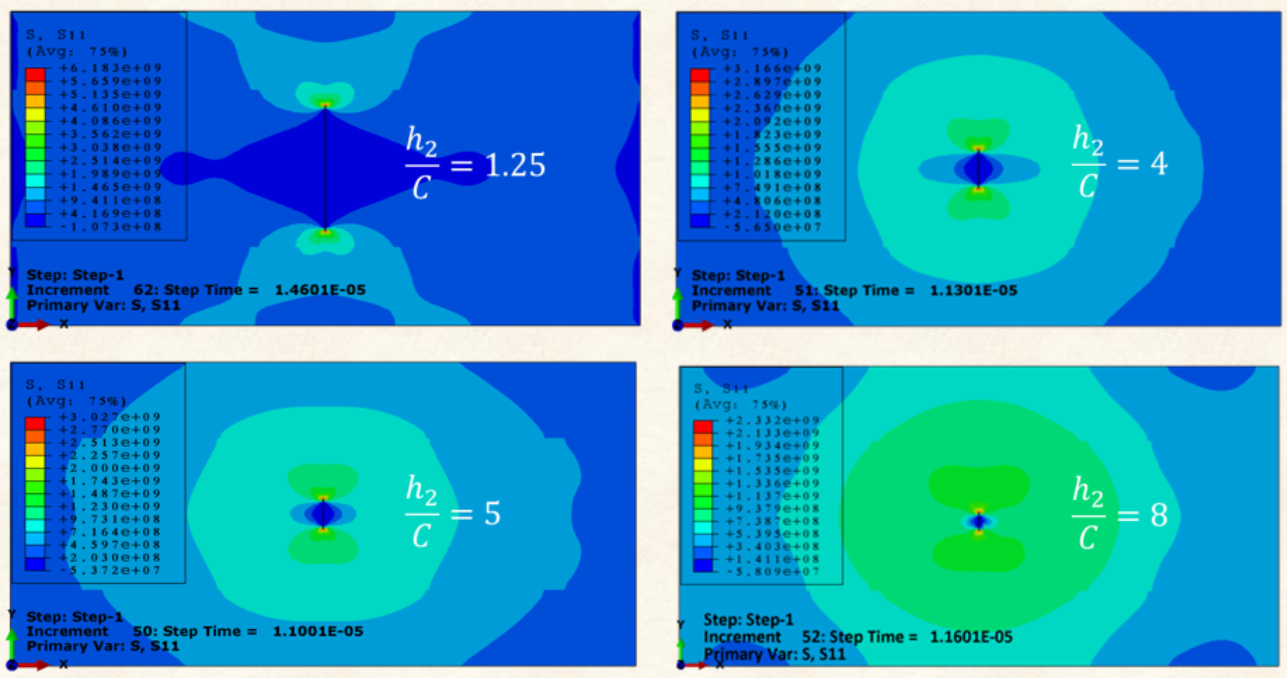
Figure 6.
Crack length effect on stress distribution for PZT-5H composite.

Figure 7.
DSIF curves versus time of PZT-5H composite.

Figure 8.
Effect of impact energy level on DSIF of (a) PZT-5H composite and (b) PZT-4 composite.


Table 1.
Comparison of the results (present results and previous works [22,24,25,26]) for the investigated case studies.
| BaTiO3 Plate’ Results Comprehension | Kmax (MPa) | Tmax (μs) | Steel Plate’ Results Comprehension | Kmax (MPa) | Tmax (μs) |
|---|---|---|---|---|---|
| Obtained results | 1.15 | 9.5 | Obtained results | 2.559 | 7 |
| Enderlein’s work | 1.15 | 9.5 | Chen’s work | 2.698 | 6 |
| Error (%) | 0.41 | 0.115 | Error (%) | 5.13 | −6.06 |
Table 2.
Materials’ properties.
| Material | Elastic Stiffnesses (× 1010 N/m2) | Piezoelectric Coefficients (C/m2) | Dielectric Constants (× 10−10 C/Vm) | ||||||
|---|---|---|---|---|---|---|---|---|---|
| PZT-4 | 13.9 | 11.3 | 2.56 | 7.43 | −6.98 | 13.8 | 12.7 | 60 | 54.7 |
| PZT-5H | 12.6 | 11.7 | 2.3 | 8.41 | −6.5 | 23.3 | 17 | 150.4 | 130 |
| Al | 8.84 | 8.84 | 2.7 | 3.43 | 0 | 0 | 0 | - | - |
| BaTiO3 | 15 | 14.6 | 4.4 | 6.6 | −4.35 | 17.5 | 11.4 | 98.7 | 112 |
| Steel (Elastic) | : 5000 kg/m3 | Poisson ratio : 0.3 | Young’s modulus : 76.923 GPa | ||||||
Table 3.
Value of the piezoelectric plates’ simulation parameters.
| h2 (mm) | h1 (mm) | h (mm) | c (mm) | ||
|---|---|---|---|---|---|
| 10 | 5 | 20 | variable | variable | 2 |
© 2018 by the authors. Licensee MDPI, Basel, Switzerland. This article is an open access article distributed under the terms and conditions of the Creative Commons Attribution (CC BY) license (http://creativecommons.org/licenses/by/4.0/).
Share and Cite
MDPI and ACS Style
Fotouhi, S.; Fotouhi, M.; Pavlovic, A.; Djordjevic, N. Investigating the Pre-Damaged PZT Sensors under Impact Traction. J. Mar. Sci. Eng. 2018, 6, 142. https://doi.org/10.3390/jmse6040142
AMA Style
Fotouhi S, Fotouhi M, Pavlovic A, Djordjevic N. Investigating the Pre-Damaged PZT Sensors under Impact Traction. Journal of Marine Science and Engineering. 2018; 6(4):142. https://doi.org/10.3390/jmse6040142
Chicago/Turabian StyleFotouhi, Sakineh, Mohamad Fotouhi, Ana Pavlovic, and Nenad Djordjevic. 2018. "Investigating the Pre-Damaged PZT Sensors under Impact Traction" Journal of Marine Science and Engineering 6, no. 4: 142. https://doi.org/10.3390/jmse6040142
Note that from the first issue of 2016, this journal uses article numbers instead of page numbers. See further details here.