
Gallium-Telluride-Based Composite as Promising Lithium Storage Material

Department of Chemical and Biological Engineering, Gachon University, Seongnam 13120, Gyeonggi, Korea
*
Authors to whom correspondence should be addressed.
Nanomaterials 2022, 12(19), 3362; https://doi.org/10.3390/nano12193362
Submission received: 18 August 2022
/
Revised: 18 September 2022
/
Accepted: 23 September 2022
/
Published: 27 September 2022
(This article belongs to the Special Issue Functionalized Nanostructures for Novel Energy Storage Systems)
Abstract
:Various applications of gallium telluride have been investigated, such as in optoelectronic devices, radiation detectors, solar cells, and semiconductors, owing to its unique electronic, mechanical, and structural properties. Among the various forms of gallium telluride (e.g., GaTe, Ga3Te4, Ga2Te3, and Ga2Te5), we propose a gallium (III) telluride (Ga2Te3)-based composite (Ga2Te3-TiO2-C) as a prospective anode for Li-ion batteries (LIBs). The lithiation/delithiation phase change mechanism of Ga2Te3 was examined. The existence of the TiO2-C hybrid buffering matrix improved the electrical conductivity as well as mechanical integrity of the composite anode for LIBs. Furthermore, the impact of the C concentration on the performance of Ga2Te3-TiO2-C was comprehensively studied through cyclic voltammetry, differential capacity analysis, and electrochemical impedance spectroscopy. The Ga2Te3-TiO2-C electrode showed high rate capability (capacity retention of 96% at 10 A g−1 relative to 0.1 A g−1) as well as high reversible specific capacity (769 mAh g−1 after 300 cycles at 100 mA g−1). The capacity of Ga2Te3-TiO2-C was enhanced by the synergistic interaction of TiO2 and amorphous C. It thereby outperformed the majority of the most recent Ga-based LIB electrodes. Thus, Ga2Te3-TiO2-C can be thought of as a prospective anode for LIBs in the future.
1. Introduction
In recent decades, the rapidly growing desire for portable electronics, electric vehicles, and smart grids has resulted in innovative Li-ion batteries (LIBs) with high energy densities. However, the conventional carbonaceous anodes utilized in LIB systems have low capacities and rate capabilities, making LIBs unsuitable for meeting the requirements of advanced devices. This has necessitated the discovery of new high-performance electrode materials [1,2,3,4,5,6,7]. Li alloys containing components, for instance, Ge, Si, Sb, and Sn, have been proposed as attractive alternatives to high-performance LIBs because their theoretical capacities are considerably higher (Li-Ge: 1384 mAh g−1, Li-Si: 3590 mAh g−1, Li-Sn: 993.4 mAh g−1, Li-Sb: 660 mAh g−1) than those of commercial graphite anodes (372 mAh g−1) [8,9,10,11,12,13,14,15,16,17,18,19,20,21,22]. However, the cycling instabilities of these alloys, which are associated with significant volume changes during Li insertion/extraction, have limited their commercialization [23,24,25,26,27,28].
With the ability to alloy with two Li-ions ((Li2Ga), Ga is deemed a feasible anode material for LIB. This provides theoretical Li-storage specific capacities of 769 mAh g−1, respectively. Furthermore, Ga anodes have high theoretical volumetric Li-storage capacities (4545 mAh cm−3) due to the high density of Ga (5.91 g cm−3 at ambient temperature) [29,30]. As a result, various Ga-based anodes have been studied; however, they generally experience liquid agglomeration during cycling because of the low melting temperature of Ga (29.8 °C), leading to low cycling performance [31,32,33,34,35,36].
Among the chalcogenide elements, S- and Se-based alloys or composite materials have been widely selected as anode materials in rechargeable LIB systems [37,38,39,40,41,42,43,44,45,46,47,48]. Te has recently been investigated as a viable electrode material for LIBs [49,50,51]. When utilized as an electrode material, Te has various advantages over other chalcogen group elements. Te possesses the highest electronic conductivity among all nonmetallic materials (approximately 2 × 10⁻² S cm−1), which is significantly greater than those of S (approximately 5 × 10⁻¹⁶ S cm−1) and Se (approximately 1 × 10⁻⁴ S cm−1). Furthermore, Te retains a high theoretical volumetric capacity (Li: 2621 mAh cm−3), which is associated with its high density (6.24 g cm−3) [51]. However, Te cannot overcome the capacity fading attributed to the large volume variation during cycling [52,53,54,55,56,57,58,59,60,61].
Various applications of gallium telluride, which is a binary compound of Ga and Te, have been studied, such as optoelectronic devices, radiation detectors, solar cells, and semiconductors, owing to its unique electronic, mechanical, and structural properties [62,63,64,65]. Among various gallium tellurides (GaTe, Ga3Te4, Ga2Te3, and Ga2Te5), Ga2Te3 is a steady compound that is odorless, black, brittle, and non-toxic. Because Ga2Te3 has a high melting point of 789 °C, and it does not undergo Ga dissolution and agglomeration during cycling, it can be safely used as a LIB anode material [66]. In addition, the high density (5.57 cm−3) of Ga2Te3 allows for high theoretical volumetric capacities for LIBs (2858 mAh cm−3) [67]. Despite these suitable features, the application of Ga2Te3 as an LIB anode material has not been studied in detail. In addition, ordinary considerations such as unstable stability, irreversible capacity, and inferior Coulombic efficiency remain significant challenges due to the large volume expansion during electrochemical reactions. Thus, an efficient strategy is needed to achieve stable and high-performance anode materials. To this end, many approaches have been investigated to resolve the aforementioned issues. The employment of diverse carbonaceous materials (including graphite, carbon nanotubes, porous carbon, carbon black, carbon fiber, and graphene (or reduced graphene oxide)) to active materials has been demonstrated as an effective approach [68,69,70,71,72,73]. The carbon-based materials not only buffer the large volume change of active materials and prevent electrode pulverization but also enhance the electrical conductivity. Nevertheless, the presence of excess carbon concentration leads to a specific capacity reduction due to its low theoretical capacity. Another strategy is to create a composite or compound that contains passive metal elements (such as Ni, Cu, Fe, Co, V, and Mo) that are alloyed with the active material to improve its mechanical and electrical conductivity [74,75,76,77,78,79]. As a last effective strategy for preventing volume change, ceramic-based materials such as TiO2, TiC, Al2O3, Si3N4, and MgO are cooperated with active materials [80,81,82,83,84]. Although certain ceramics possess low specific capacities, they can prevent agglomeration and volume changes in the active material owing to their great mechanical properties.
In this work, we synthesized a Ga2Te3-based composite electrode (Ga2Te3-TiO2-C) using simple high-energy ball milling (HEBM) and demonstrated its suitability for LIB anodes. The feasibility of the Ga2Te3-TiO2-C anode for LIBs was examined by performing galvanostatic measurements, differential capacity analysis, and electrochemical impedance spectroscopy (EIS). More importantly, the Li insertion/extraction electrochemical phase-change mechanism of Ga2Te3-TiO2-C anodes was studied via ex situ X-ray diffraction (XRD) analysis. The optimal C concentration of the Ga2Te3-TiO2-C composite was determined through various electrochemical measurements of the as-prepared LIBs. Ga2Te3-TiO2-C (10%) exhibited high cycling and rate performances comparable to those of the most recent Ga-based electrodes.
2. Experimental Materials and Methods
2.1. Material Synthesis
Ga2Te3 was synthesized using simple HEBM, as shown in Figure 1. In the first step, a mixture of Ga2O3 (99.99%, Sigma Aldrich, St. Louis, MI, USA), Te powder (99.8%, Alfa Aesar, Haverhill, MA, USA), and Ti (325 mesh, 99.99%, Alfa Aesar), in a molecular ratio of 2:3:6 was placed in a bowl containing zirconium oxide balls. The ratio of the balls and powder mixture was 20:1. The powder compound was ball milled for 10 h at 300 rpm under an Ar atmosphere. In the second step, the obtained powder (Ga2Te3-TiO2) was mixed with acetylene carbon black powder (C) (99.9+%, Alfa Aesar, bulk density: 170–230 g L−1, S.A.: 75 m2 g−1) in mass ratios of 9:1, 8:2, and 7:3 (denoted as Ga2Te3-TiO2-C (10%), Ga2Te3-TiO2-C (20%), and Ga2Te3-TiO2-C (30%), respectively). These combinations were manually ground and then subjected to a 10-h ball milling process under identical conditions as the initial milling. The following is the mechanochemical reaction route for synthesizing Ga2Te3-TiO2-C:
First step:
2Ga2O3 + 6Te + 3Ti → 2Ga2Te3 + 3TiO2 (Ga2Te3-TiO2)
Second step:
Ga2Te3-TiO2 + C → Ga2Te3-TiO2-C
2.2. Material Characterization
Ga2Te3-TiO2 and Ga2Te3-TiO2-C crystal structures were determined using powder XRD (D/MAX-2200 Rigaku, Japan) with Cu Kα (λ = 1.54 Ả) radiation at a scan rate of 2° min−1. High-resolution transmission electron microscopy (HRTEM, JEOL JEM-2100F), scanning electron microscopy (SEM, Hitachi S4700, Japan), and energy-dispersive X-ray spectroscopy (EDXS) were employed to examine the microscopic morphology of the as-synthesized composite materials. The chemical states of the produced materials were assessed using X-ray photoelectron (XP) spectroscopy (XPS, Kratos Axis Anova). Ga2Te3-TiO2-C anode reaction process was investigated using ex situ XRD.
2.3. Electrochemical Measurements
A conventional casting technique was used to prepare all of the electrodes. Briefly, a slurry including the active material, poly (acrylic acid) (PAA, Mw 450000, Sigma Aldrich) binder, and conductive carbon (Super-P, 99.9%, Alfa Aesar) in a ratio of 7.0:1.5:1.5 (w/w) was dissolved into the N-methyl-2-pyrolidone (NMP) solution with the solid-to-liquid ratio of 1:12.5, and then casted on a Cu foil current collector. The cast electrodes were transferred to an Ar gas-filled glove box for cell assembly after being dried in a vacuum oven overnight at 70 °C to completely eliminate the solvent residue. For half-cell testing, a coin-type cell (CR2032) was utilized with Li metal foil as a counter electrode, polyethylene as a separating membrane, and 1 M LiPF6 in diethyl carbonate/ethylene carbonate (1:1 by v/v) as an electrolyte. Using a battery-testing device ((WBCS3000, WonATech, South Korea), the electrochemical performance of Ga2Te3-TiO2-C was assessed. When compared to Li/Li+, a 0.01 to 2.5 V voltage range was applied to establish the galvanostatic charge–discharge (GCD) profile. To describe the electrochemical responses of the electrodes with Li+, cyclic voltammetry (CV) analyses were conducted at a scanning rate of 0.1 mV s−1. A battery cycler (WBCS3000, WonATech) was used to measure the rate capability at various current densities (0.1, 0.5, 1, 3, 5, and 10 A g−1), and the current densities are calculated based on the per gram Ga2Te3. The EIS was conducted using a ZIVE MP1 (WonaTech) analyzer in the frequency range of 100 kHz–100 MHz at an AC amplitude of 10 mV.
3. Results and Discussion
The XRD pattern of the as-synthesized Ga2Te3-TiO2 obtained by HEBM is shown in Figure 2a. The XRD pattern was the same as that of monoclinic Ga2Te3. The peaks at 26.2°, 30.3°, 43.4°, 51.4°, 53.8°, 63.0°, 69.4°, and 79.5° corresponded to the (111), (200), (220), (311), (222), (400), (331), and (422) planes of Ga2Te3, respectively. The relatively small peaks observed at 28.6°, 33.3°, 44.5°, and 75.6° were attributed to the (002), (311), (601), and (623) planes of TiO2, respectively. The insignificant TiO2 peaks below 20° are associated with the low TiO2 content in the composite (as shown in Figure S1) [85,86]. The addition of amorphous C decreased the crystallinity of Ga2Te3 and TiO2 in Ga2Te3-TiO2-C (Figure S2) [87]. It was clear that the target product had been completely transformed from the raw elements by a solid-state reaction because there were no impurity peaks for the precursor components (Ga, Ti, Te or Ga2O3). The chemical bonding of Ga2Te3-TiO2-C (10%) was assessed using XPS (Figure 2b–g). The presence of Ga, Te, O, Ti, and C in Ga2Te3-TiO2-C (10%) was shown in the XPS survey spectrum in Figure 2b, along with their specific binding energies. The Ga 3d orbital level signal in Figure 2c corresponded to Ga 3d3/2 (20.9 eV) and Ga 3d5/2 (19.8 eV), whereas the peaks in Figure 2d were ascribed to Te 3d3/2 (583.9 eV) and Te 3d5/2 (573.6 eV), which confirms the formation of Ga2Te3 alloy after the HEBM process. Furthermore, the existence of Te-O bonding with signals at 576.0 and 586.4 eV (Figure 2d) on the Ga2Te3-TiO2-C (10%) surface implied that partial surface oxidation of active Ga2Te3 [88,89]. Although obvious oxidation is observed for Ga2Te3, the air does not seem to have too much of an effect on anode composites. Indeed, there were no impurities nor significant compositional changes for the composite anode (Figure S7) compared with the as-synthesized Ga2Te3-TiO2-C (10%) powder (Figure S4). In addition, oxidation was mainly observed for Te due to the Te-rich compound of Ga2Te3. As shown in Figure S1, the atomic percent of Te (27%) was greater than that of Ga (17%). Therefore, Te sites seem to be more affected by the rapid oxidation in air [90]. Ga 3D hybridization was found because of the constitution of the O 2 s peak at 23.7 eV [86,91]. Regarding the formation of TiO2, Ti-O binding was demonstrated through the detection of the orbital level signals of Ti 2p3/2 (458.9 eV) and Ti 2p1/2 (464.6 eV) (Figure 2e) along with the O 1 s peak (530.9 eV) (Figure 2f). More importantly, the binding energy level in the O 1 s spectrum at 532.3 eV (Figure 2f) showed the formation of hydroxide groups on the active surface of Ga2Te3, implying hydrogen bond formation with functional moieties (carboxylate functional groups) of PAA binder due to its possessing high affinity. The strong binding between the PAA binder and hydroxides on Ga2Te3 is expected to prevent particle agglomeration and maintain good contact between the current collector and electrode [86,92]. The XPS results of C 1 s in Figure 2g showed binding energies at 284.6, 285.0, and 285.9 eV, which indicate C–C, C–O–C, and C–O=C bonds, respectively. These results confirmed the constitution of the target ternary composites (Ga2Te3, TiO2, and C for Ga2Te3-TiO2-C (10%)).
Morphological and structural analyses of Ga2Te3-TiO2-C (10%) were investigated using SEM, HRTEM, and EDXS, as shown in Figure 3. The SEM images showed that the particle size ranged from submicrometers to a few micrometers (Figure 3a,b). The HRTEM images (Figure 3c and Figure S3) revealed crystalline lattice spacings of 0.340, 0.294, 0.208, and 0.170 nm, which corresponded to the (111), (200), (220), and (222) planes of Ga2Te3, respectively, and 0.311 nm attributed to the (002) plane of TiO2. Additionally, amorphous C was created as a flat surface layer around Ga2Te3 and TiO2, and it was anticipated to serve as a buffering matrix for the active material. In the Ga2Te3-TiO2-C (10%) sample, the EDXS mapping analysis of the scanning transmission electron microscopy image (Figure 3d) revealed a homogeneous dispensation of each element (Ga, Te, Ti, O, and C). Furthermore, the SEM–EDXS analysis results (Figure S4) of Ga2Te3-TiO2-C (10%) consistently showed that the component elements were uniformly scattered throughout the composite. Additionally, the quantitative examination of the EDS results demonstrated that the stoichiometric ratio of the component elements was nearly similar to the theoretical values.
Ga2T3-TiO2-C with various C content for LIBs was investigated electrochemically using half-cells electrode systems (Figure 4). The GCD voltage profiles of Ga2Te3-TiO2-C (10%), Ga2Te3-TiO2-C (20%), and Ga2Te3-TiO2-C (30%) are shown in Figure 4a and Figure S8. The first discharge/charge performance of Ga2Te3-TiO2-C (10%), Ga2Te3-TiO2-C (20%), and Ga2Te3-TiO2-C (30%) were 892/677, 837/586, and 789/568 mAh g−1, respectively, which corresponded to initial Coulombic efficiencies (ICEs) of 75.9%, 70.0%, and 71.9%, respectively. The three electrodes experienced irreversible capacity losses in the initial cycle that were attributed to the development of a solid electrolyte interfacial (SEI) layer. On the basis of the EDXS results (Figure S4) and the computed theoretical capacities of the separate elements (Table S1), the capacity contributions of C and TiO2 to Ga2Te3-TiO2-C (10%) were estimated to be ~9% and ~16%, respectively. Therefore, active Ga2Te3 (75% of the total capacity) was the principal source of the capacity of the electrode. The primary role of C and TiO2 was as a buffering matrix (25% capacity involvement), which reduced the volume variation of the active material. Furthermore, the theoretical capacity contribution of different components in Ga2Te3-TiO2-C (20 and 30%) was also determined (Tables S2 and S3). Compared with Ga2Te3-TiO2-C (10%), increase in the C concentration results in a decrease in the capacity contribution of active material. Based on Figures S4–S6 and Tables S1–S3, the calculated capacity contribution of the active material Ga2Te3 was 75, 61, and 53%, resulting in the actual Ga2Te3 capacity of ~576, ~401, and ~314 mAh g−1 for the Ga2Te3-TiO2-C (10%), Ga2Te3-TiO2-C (20%), and Ga2Te3-TiO2-C (30%), respectively. Notably, the measured capacities of Ga2Te3-TiO2-C (10%) and Ga2Te3-TiO2 (455 and 477 mAh g−1, respectively, as computed in Table S4) that were higher than their theoretical capacities are most likely ascribed to the interfacial Li-ion storage and electrolyte decomposition. The specific performance of the lowest C content electrode (Ga2Te3-TiO2-C (10%)) was the highest in terms of stability and capacity. It reached 768.9 mAh g−1 with capacity retention (CR) of 99.8% after 300 cycles at 100 mA g−1 (Figure 4b). The specific capacities of Ga2Te3-TiO2-C (20%) and Ga2Te3-TiO2-C (30%) were 587.3 and 585.3 mAh g−1 after 300 cycles at 100 mA g−1, respectively, which corresponded to a CR of 89.2% and 98.7%, respectively. This behavior was further explained using Coulombic efficiency (CE, Table S5) and differential capacity plot (DCP) analyses of the first 300 cycles (Figure S9). The CE increased gradually and steadily. Particularly, the CE achieved almost 99.13% after 150 cycles, with the possibility that side reactions were involved until this point. Then, the CE decreased slightly and stabilized at 98.5% after 300 cycles. The DCP analysis showed that the main reduction peaks (at ~1.22 and ~1.69 V) remained unchanged for 300 cycles. However, the oxidation peaks (at ~0.41, ~0.98, and ~1.25 V) were stable for 100 cycles, after which they became broader and shifted toward a high voltage. Nevertheless, this polarization had an almost negligible effect on the lithiation/delithiation, resulting in a stable capacity after 300 cycles. This was because the TiO2 matrix and lowest C content (10%) effectively prevented the side reactions that could result from good electrode–electrolyte contact at 100 mA g−1. At 500 mA g−1, a similar trend was observed (Figure 4c). In this instance, the performance increased until 250 cycles, then slightly decreased, and finally became saturated (~600 mAh g−1). The CE variation (Table S6) and DCP analysis both showed this tendency (Figures S10 and S11). According to Figure S10, the magnitudes of the reduction (at ~0.98 and ~1.69 V) and the oxidation (at ~0.41, ~1.58, and ~1.85 V) rose for 200 cycles with a decrease in polarization and then reduced after 200 cycles with a minor increase in polarization. This was followed by a reduction in polarization after 400 cycles (Figure S11). Therefore, although the capacity decreased from 250 cycles to 400 cycles, it saturated after 400 cycles. Under a high current density, an electrode requires demanding lithiation/delithiation conditions (500 mA g−1). This makes it more difficult to achieve steady and stable cycling [93,94,95]. To comprehend the steady rise in the performance, the variations in the DCP curves, as a function of the cycle number, were studied at 100 and 500 mA g−1 (Figure S12). The DCP curves of the Ga2Te3-TiO2-C (10%) electrode showed that the overall intensity of the redox peaks were relatively stable as the cycle number increased at 100 mA g−1, indicating a stable capacity until 300 cycles. However, at 500 mA g−1, the overall magnitudes of the redox peaks rose with the cycle number until 300 cycles, reduced from 300 cycles to 400 cycles, and became saturated after 400 cycles. The CE variations at 100 and 500 mA g−1 of Ga2Te3-TiO2-C with varied C concentrations were compared in Figure S13. The detailed CE values for the Ga2Te3-TiO2-C (10%), Ga2Te3-TiO2-C (20%), and Ga2Te3-TiO2-C (30%) electrodes over the first ten cycles are described in Table S7 (at 100 mA g−1) and Table S8 (at 500 mA g−1). As displayed in Table S7, the ICE of the Ga2Te3-TiO2-C (10%) electrode (75.9%) were slightly higher than those of the Ga2Te3-TiO2-C (20%) (ICE = 69.9%) and Ga2Te3-TiO2-C (30%) electrodes (ICE = 72.1%). The CE of the Ga2Te3-TiO2-C (10%) electrode was the highest after ten cycles. At 500 mA g−1, it revealed a similar tendency (Table S8). After the first cycle, the high CE of the Ga2Te3-TiO2-C (10%) electrode suggested that lithiation/delithiation was highly reversible. The Ga2Te3-TiO2-C (10%) CV curves for the first five cycles in the voltage range of 0.01–2.5 V vs. Li/Li+ were shown in Figure 4d. Due to SEI layer formed on the electrode surface, the CV curve in the first cycle was noticeably different from that of the subsequent cycles. The intercalation of Li into Ga2Te3 to form Li2Te and Ga is indicated by a substantial reduction peak at 1.37 V in the first discharge. The peak at 0.98 V was responsible for the interaction between Ga and Li to generate Li2Ga. Thus, Li2Te and Li2Ga were the final products after the discharge step was completed. The three oxidation peaks were shown at 0.92, 1.56, and 1.88 V in the charge process. The first peak was caused by the complete exclusion of Li, turning Li2Ga into Ga. Ga began to intrude into Li2Te to form Ga2Te3 when the anode was charged to 1.56 and 1.88 V. In the ex situ analyses, this phase change is examined in detail. After the second cycle, the curves nearly overlapped, indicating the excellent reversibility and stability of Ga2Te3-TiO2-C (10%). Compared to Ga2Te3-TiO2-C (10%), Ga2Te3-TiO2-C (20%) and Ga2Te3-TiO2-C (30%) showed similar stability in terms of the polarization of the reduction and oxidation peaks after the second cycle (Figure S14). The control experiments of Ga2Te3-TiO2-C (10%) with PVDF were conducted to better define the role of the PAA binder. The oxidation occurring on the Ga2Te3 surface positively affects the electrochemical performance by stabilizing the electrode structure through hydrogen bonding between hydroxyl groups in Ga2Te3 and carboxylate groups in the PAA binder. As shown in Figure S15, the cyclic performance of the composite with PAA binder showed significantly enhanced performance compared to the composite with PVDF. Besides, CV curves do not overlap with the increase in the cycle number for the composite with PVDF, indicating the irreversible cycling behavior. This result is consistent with the previous study in which the cycling performance of oxidized active material was enhanced with PAA binder [86]. The rate performances (Figure 4e) and normalized capacity retention values (Figure 4f) of the electrodes were studied at different current densities. In Figure 4e, the average discharge capacities of Ga2Te3-TiO2-C (10%) were significantly greater than those of Ga2Te3-TiO2-C (20%) and Ga2Te3-TiO2-C (30%), which were 708, 706, 687, 665, 636, and 613 mAh g−1 at current densities of 0.1, 0.5, 1.0, 3.0, 5.0, and 10.0 A g−1, respectively. Surprisingly, even at a high current density of 10 A g−1, Ga2Te3-TiO2-C (10%) had capacity retention of up to 96% (Figure 4f). Furthermore, Ga2Te3-TiO2-C (10%) showed high rate performance when the discharge rate was reduced from 10 A g−1 to 0.1 A g−1, resulting in high-capacity retention (99%).
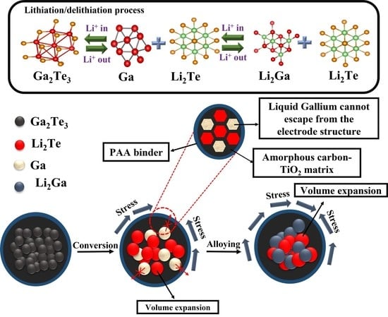
The phase change mechanism during the lithiation/delithiation process of the Ga2Te3-TiO2-C(10%) electrode was investigated using ex situ XRD (Figure 5a). Peaks corresponding to Li2Te and Ga were observed at a discharge voltage of 1.37 V (D-1.37 V). When the electrode was completely discharged (D-5 mV), Li2Ga peaks emerged and Li2Te peaks remained. The Li2Ga phase partly disappeared when the electrode was charged to 0.92 V (C-0.92 V). In the charging state at 1.56 V, the Li2Te phase partly disappeared, Ga was observed, and Li2Ga completely disappeared. Only the peaks corresponding to Ga2Te3 were observed again when the electrode was completely charged to 2.5 V (C-2.5 V). Ga2Te3 undergoes structural changes during first lithiation/delithiation as follows:
Discharging:
Ga2Te3 → Li2Te + Ga → Li2Te + Li2Ga
Charging:
Li2Te + Li2Ga → Li2Te + Ga → Ga2Te3
It is noteworthy that after the first cycle, the Ga2Te3 phase (major peaks at 51.4°, 53.8°, and 69.4°) was completely restored with no impurity peaks, showing the highly reversible interaction of Ga2Te3 with Li-ions. The active material was well shielded from pulverization and delamination because of volume expansion thanks to the strong binding between Ga2Te3 and TiO2-C. As schematically shown in Figure 5b, the ex situ XRD result demonstrated the alloying/dealloying and conversion mechanism of the Ga2Te3 electrode during the first charge/discharge process.
At the 1st, 5th, and 20th cycles, the EIS profiles of the Ga2Te3-TiO2-C (10%), Ga2Te3-TiO2-C (20%), and Ga2Te3-TiO2-C (30%) electrodes were obtained (Figure 6). The equivalent circuit to fit EIS profile shown in Figure 6d includes the SEI layer resistance (RSEI), charge–transfer resistance (Rct), electrolyte resistance (Rb), interfacial double-layer capacitance (Cdl), constant phase element (CPE), and Warburg impedance (Zw). Rct at the electrode–electrolyte interface is shown by compressed semicircles in the mid-frequency region of the Nyquist plots. As the number of cycles grew from 1 to 20, cells containing various concentrations of C displayed decreasing sizes of semicircles, suggesting that Rct decreased (Figure 6a–c). Ga2Te3-TiO2-C (10%) showed the lowest value of Rct after 20 cycles (Table S9), indicating the optimal charge transport circumstances, which resulted in the highest electrochemical performance.
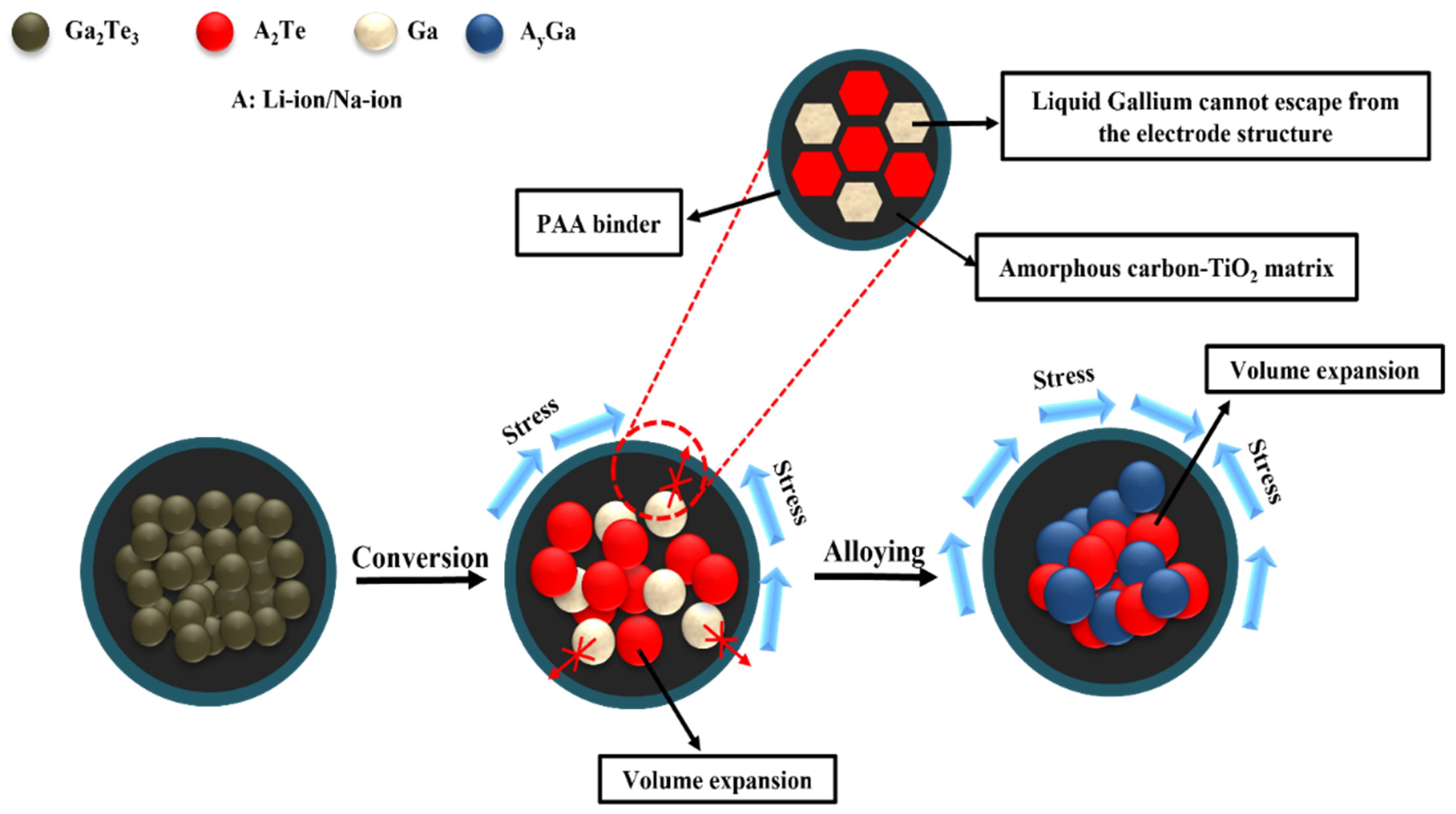
The electrochemical Li-storage behaviors were determined from the above results. Because amorphous C was delivered as a buffer to limit volume expansion during the lithiation/delithiation process, the cyclic performance was stable. Nevertheless, the regulation of the C content played an important role. A C content of 10% was sufficient to achieve high electrochemical efficiency for the LIBs. When the C content was increased, the specific capacity was rather decreased due to the reduced active material in the composite. In addition, TiO2 synergistically prevented electrode pulverization and improved Li-ion diffusion. Therefore, the Ga2Te3-TiO2-C (10%) electrode showed high electrochemical performance and fast kinetics due to the cooperative impact of the TiO2-C hybrid matrix, as demonstrated in Figure 7. Accordingly, the capacity of the Ga2Te3-TiO2-C (10%) electrode was higher than those of recently reported Ga-based anodes for LIBs (Table 1).
4. Conclusions
Ga2Te3-TiO2-C was successfully prepared via HEBM and investigated as a propitious anode material for LIBs. The morphology, chemical state, and crystal structure of Ga2Te3-TiO2-C were investigated through XRD analysis, SEM, EDXS, HRTEM, and XPS. To identify the conversion/recombination reaction mechanism of the Ga2Te3 anode during the lithiation/delithiation processes, ex situ XRD analysis was studied. The major strategy for achieving high capacity and long-term cycling performance for the Ga2Te3-TiO2-C nanocomposite was to homogeneously embed nanoconfined Ga2Te3 crystallites within an electronically conductive TiO2-C matrix. This promoted Li-ion diffusion kinetics and improved the mechanical stability by accommodating the change in the volume of the Ga2Te3 particles and preventing the agglomeration of Ga. As a result, the Ga2Te3-TiO2-C electrode showed high rate capability (CR of 96% at 10 A g−1 compared to 0.1 A g−1), as well as great reversible specific capacity (769 mAh g−1 at 100 mA g−1 after 300 cycles). It thereby outperformed the majority of the most recent Ga-based LIB electrodes. The electrochemical performance of Ga2Te3-TiO2-C was enhanced by the synergistic interaction of TiO2 and amorphous C. Thus, Ga2Te3-TiO2-C can be thought of as a prospective anode material for LIBs of the future.
Supplementary Materials
The following supporting information can be downloaded at: https://www.mdpi.com/article/10.3390/nano12193362/s1, Figure S1: EDX spectrum of as-synthesized Ga2Te3-TiO2, Figure S2: XRD pattern of Ga2Te3-TiO2-C with different concentration of C, Figure S3: HRTEM image of Ga2Te3-TiO2-C(10%), Figure S4: EDX spectrum of as-synthesized Ga2Te3-TiO2-C(10%), Figure S5: EDX spectrum of as-synthesized Ga2Te3-TiO2-C(20%), Figure S6: EDX spectrum of as-synthesized Ga2Te3-TiO2-C(30%), Figure S7: EDX spectrum of Ga2Te3-TiO2-C(10%) anode, FigureS8: Galvanostatic discharge-charge profiles of (a) Ga2Te3-TiO2-C(20%) and (b) Ga2Te3-TiO2-C(30%), Figure S9: DCP profiles of Ga2Te3-TiO2-C(10%) during 300 cycles measured at 100 mA g−1: (a) 1−150 cycles and (b) 150−300 cycle. Enlarged view of (c) reduction and (d) oxidation peaks, Figure S10: (a) DCP profiles of Ga2Te3-TiO2-C(10%) during initial 200 cycles measured at 500 mA g−1. Enlarged view of (b) oxidation and (c) reduction peaks, Figure S11: DCP profiles of Ga2Te3-TiO2-C(10%) from 300 cycle to 500 cycles measured at 500 mA g−1. Enlarged view of (b) oxidation and (c) reduction peaks, Figure S12: DCP profiles of Ga2Te3-TiO2-C(10%) at current density (a) at 100 mA g−1 and during 300 cycles and (b) at 500 mA g−1 during 500 cycles, Figure S13: Coulombic efficiency of Ga2Te3-TiO2 with different C content at current densities of (a) 100 and (b) 500 mA g−1, Figure S14: CV curves of (a) Ga2Te3-TiO2-C(20%) and (b) Ga2Te3-TiO2-C(30%) for LIBs, Figure S15: (a) Cycling performance of Ga2Te3-TiO2-C (10%) with PAA and PVDF binder, (b) CV curves of Ga2Te3-TiO2-C(10%) with PVDF binder, Table S1: Calculation of capacity contribution of Ga2Te3, TiO2 and C in the Ga2Te3-TiO2-C(10%) composite in LIB, Table S2: Calculation of capacity contribution of Ga2Te3, TiO2 and C in the Ga2Te3-TiO2-C(20%) composite in LIB, Table S3: Calculation of capacity contribution of Ga2Te3, TiO2 and C in the Ga2Te3-TiO2-C(30%) composite in LIB, Table S4: Calculation of theoretical capacity of Ga2Te3-TiO2-C(10%) and Ga2Te3-TiO2 in LIB, Table S5: Coulombic efficiency variation of Ga2Te3-TiO2-C (10%) at various cycle numbers measured at 100 mA g−1 for LIB, Table S6: Coulombic efficiency variation of Ga2Te3-TiO2-C(10%) at various cycle numbers measured at 500 mA g−1 for LIB, Table S7: Coulombic efficiency of Ga2Te3-TiO2-C at current density of 100 mA g−1 during initial 10 cycles for LIB, Table S8: Coulombic efficiency of Ga2Te3-TiO2-C at current density of 500 mA g−1 during initial 10 cycles for LIB, Table S9: Charge-transfer resistance (Rct) of Ga2Te3-TiO2-C for LIB.
Author Contributions
Conceptualization, J.H. and I.T.K.; methodology, J.H. and V.P.H.H.; validation, V.P.H.H.; investigation, V.P.H.H.; data curation, V.P.H.H.; writing—original draft preparation, V.P.H.H.; writing—review and editing, J.H. and I.T.K.; supervision, J.H. and I.T.K.; funding acquisition, J.H. All authors have read and agreed to the published version of the manuscript.
Funding
This work was supported by the Gachon University research fund of 2019 (GCU-2019-0805) and the Basic Science Research Capacity Enhancement Project through a Korea Basic Science Institute (National Research Facilities and Equipment Center) grant funded by the Ministry of Education (2019R1A6C1010016).
Institutional Review Board Statement
Not applicable.
Informed Consent Statement
Not applicable.
Data Availability Statement
The data is available on reasonable request from the corresponding author.
Conflicts of Interest
The authors declare no competing interests.
References
- Dunn, B.; Kamath, H.; Tarascon, J.M. Electrical energy storage for the grid: A battery of choices. Science 2011, 334, 928–935. [Google Scholar] [CrossRef]
- Etacheri, V.; Marom, R.; Elazari, R.; Salitra, G.; Aurbach, D. Challenges in the development of advanced Li-ion batteries: A review. Energy Environ. Sci. 2011, 4, 3243–3262. [Google Scholar] [CrossRef]
- Armand, M.; Tarascon, J.M. Building better batteries. Nature 2008, 451, 652–657. [Google Scholar] [CrossRef] [PubMed]
- Huggins, R.A. Advanced Batteries: Materials Science Aspects; Springer Science & Business Media: Berlin, Germany, 2009; pp. 1–474. [Google Scholar]
- Reddy, M.V.; Rao, G.V.S.; Chowdari, B.V.R. Metal Oxides and Oxysalts as Anode Materials for Li Ion Batteries. Chem. Rev. 2013, 113, 5364–5457. [Google Scholar] [CrossRef]
- Weng, W.; Li, J.; Du, Y.; Ge, X.; Zhou, X.; Bao, J. Template-free synthesis of metal oxide hollow micro-/nanospheres via Ostwald ripening for lithium-ion batteries. J. Mater. Chem. A 2018, 6, 10168–10175. [Google Scholar] [CrossRef]
- Zou, R.; Xu, M.; He, S.-A.; Han, X.; Lin, R.; Cui, Z.; He, G.; Brett, D.J.L.; Guo, Z.X.; Hu, J.; et al. Cobalt nickel nitride coated by a thin carbon layer anchoring on nitrogen-doped carbon nanotube anodes for high-performance lithium-ion batteries. J. Mater. Chem. A 2018, 6, 19853–19862. [Google Scholar] [CrossRef]
- Chen, X.; Zhou, J.; Li, J.; Luo, H.; Mei, L.; Wang, T.; Zhang, Y. A germanium and zinc chalcogenide as an anode for a high-capacity and long cycle life lithium battery. RSC Adv. 2019, 9, 35045–35049. [Google Scholar] [CrossRef] [PubMed]
- Ashuri, M.; He, Q.; Shaw, L.L. Silicon as a potential anode material for Li-ion batteries: Where size, geometry and structure matter. Nanoscale 2016, 8, 74–103. [Google Scholar] [CrossRef]
- Mou, H.; Xiao, W.; Miao, C.; Li, R.; Yu, L. Tin and Tin Compound Materials as Anodes in Lithium-Ion and Sodium-Ion Batteries: A Review. Front. Chem. 2020, 8, 141. [Google Scholar] [CrossRef]
- He, J.; Wei, Y.; Zhai, T.; Li, H. Antimony-based materials as promising anodes for rechargeable lithium-ion and sodium-ion batteries. Mater. Chem. Front. 2018, 2, 437–455. [Google Scholar] [CrossRef]
- Nguyen, T.P.; Kim, I.T. Ag Nanoparticle-Decorated MoS2 Nanosheets for Enhancing Electrochemical Performance in Lithium Storage. Nanomaterials 2021, 11, 626. [Google Scholar] [CrossRef] [PubMed]
- Nguyen, T.P.; Kim, I.T. Self-Assembled Few-Layered MoS2 on SnO2 Anode for Enhancing Lithium-Ion Storage. Nanomaterials 2020, 10, 2558. [Google Scholar] [CrossRef] [PubMed]
- Preman, A.N.; Lee, H.; Yoo, J.; Kim, I.T.; Saito, T.; Ahn, S.-K. Progress of 3D network binders in silicon anodes for lithium ion batteries. J. Mater. Chem. A 2020, 8, 25548–25570. [Google Scholar] [CrossRef]
- Nguyen, T.P.; Kim, I.T. W2C/WS2 Alloy Nanoflowers as Anode Materials for Lithium-Ion Storage. Nanomaterials 2020, 10, 1336. [Google Scholar] [CrossRef]
- Kim, W.S.; Vo, T.N.; Kim, I.T. GeTe-TiC-C Composite Anodes for Li-Ion Storage. Materials 2020, 13, 4222. [Google Scholar] [CrossRef] [PubMed]
- Vo, T.N.; Kim, D.S.; Mun, Y.S.; Lee, H.J.; Ahn, S.-K.; Kim, I.T. Fast charging sodium-ion batteries based on Te-P-C composites and insights to low-frequency limits of four common equivalent impedance circuits. Chem. Eng. J. 2020, 398, 125703. [Google Scholar] [CrossRef]
- Hoang Huy, V.P.; Kim, I.T.; Hur, J. The Effects of the Binder and Buffering Matrix on InSb-Based Anodes for High-Performance Rechargeable Li-Ion Batteries. Nanomaterials 2021, 11, 3420. [Google Scholar] [CrossRef]
- Nguyen, Q.H.; Phung, V.D.; Kidanu, W.G.; Ahn, Y.N.; Nguyen, T.L.; Kim, I.T. Carbon-free Cu/SbxOy/Sb nanocomposites with yolk-shell and hollow structures as high-performance anodes for lithium-ion storage. J. Alloys Compd. 2021, 878, 160447. [Google Scholar] [CrossRef]
- Nguyen, P.T.; Kim, I.T. In Situ Growth of W2C/WS2 with Carbon-Nanotube Networks for Lithium-Ion Storage. Nanomaterials 2022, 12, 1003. [Google Scholar] [CrossRef]
- Nguyen, T.P.; Kim, I.T. Boron Oxide Enhancing Stability of MoS2 Anode Materials for Lithium-Ion Batteries. Materials 2022, 15, 2034. [Google Scholar] [CrossRef]
- Phan Nguyen, T.; Giang, T.T.; Kim, I.T. Restructuring NiO to LiNiO2: Ultrastable and reversible anodes for lithium-ion batteries. Chem. Eng. J. 2022, 437, 135292. [Google Scholar] [CrossRef]
- Park, C.-M.; Kim, J.-H.; Kim, H.; Sohn, H.-J. Li-alloy based anode materials for Li secondary batteries. Chem. Soc. Rev. 2010, 39, 3115–3141. [Google Scholar] [CrossRef] [PubMed]
- Obrovac, M.N.; Chevrier, V.L. Alloy Negative Electrodes for Li-Ion Batteries. Chem. Rev. 2014, 114, 11444–11502. [Google Scholar] [CrossRef]
- Zhou, X.; Guo, Y.-G. A PEO-assisted electrospun silicon–graphene composite as an anode material for lithium-ion batteries. J. Mater. Chem. A 2013, 1, 9019–9023. [Google Scholar] [CrossRef]
- Su, X.; Wu, Q.; Li, J.; Xiao, X.; Lott, A.; Lu, W.; Sheldon, B.W.; Wu, J. Silicon-Based Nanomaterials for Lithium-Ion Batteries: A Review. Adv. Energy Mater. 2014, 4, 1300882. [Google Scholar] [CrossRef]
- Seo, J.-U.; Park, C.-M. Nanostructured SnSb/MOx (M = Al or Mg)/C composites: Hybrid mechanochemical synthesis and excellent Li storage performances. J. Mater. Chem. A 2013, 1, 15316–15322. [Google Scholar] [CrossRef]
- Li, H.; Yamaguchi, T.; Matsumoto, S.; Hoshikawa, H.; Kumagai, T.; Okamoto, N.L.; Ichitsubo, T. Circumventing huge volume strain in alloy anodes of lithium batteries. Nat. Commun. 2020, 11, 1584. [Google Scholar] [CrossRef] [PubMed]
- Moskalyk, R. Gallium: The Backbone of the Electronics Industry. Miner. Eng. 2003, 16, 921–929. [Google Scholar] [CrossRef]
- Lee, K.T.; Jung, Y.S.; Kim, T.; Kim, C.H.; Kim, J.H.; Kwon, J.Y.; Oh, S.M. Liquid Gallium Electrode Confined in Porous Carbon Matrix as Anode for Lithium Secondary Batteries. Electrochem. Solid-State Lett. 2008, 11, A21. [Google Scholar] [CrossRef]
- Yang, W.; Zhang, X.; Tan, H.; Yang, D.; Feng, Y.; Rui, X.; Yu, Y. Gallium-based anodes for alkali metal ion batteries. J. Energy Chem. 2021, 55, 557–571. [Google Scholar] [CrossRef]
- Deshpande, R.D.; Li, J.; Cheng, Y.-T.; Verbrugge, M.W. Liquid Metal Alloys as Self-Healing Negative Electrodes for Lithium Ion Batteries. J. Electrochem. Soc. 2011, 158, A845. [Google Scholar] [CrossRef]
- Yarema, M.; Wörle, M.; Rossell, M.D.; Erni, R.; Caputo, R.; Protesescu, L.; Kravchyk, K.V.; Dirin, D.N.; Lienau, K.; von Rohr, F.; et al. Monodisperse Colloidal Gallium Nanoparticles: Synthesis, Low Temperature Crystallization, Surface Plasmon Resonance and Li-Ion Storage. J. Am. Chem. Soc. 2014, 136, 12422–12430. [Google Scholar] [CrossRef] [PubMed]
- Liang, W.; Hong, L.; Yang, H.; Fan, F.; Liu, Y.; Li, H.; Li, J.; Huang, J.Y.; Chen, L.-Q.; Zhu, T.; et al. Nanovoid Formation and Annihilation in Gallium Nanodroplets under Lithiation–Delithiation Cycling. Nano Lett. 2013, 13, 5212–5217. [Google Scholar] [CrossRef]
- Guo, X.; Zhang, L.; Ding, Y.; Goodenough, J.B.; Yu, G. Room-temperature liquid metal and alloy systems for energy storage applications. Energy Environ. Sci. 2019, 12, 2605–2619. [Google Scholar] [CrossRef]
- Zhu, J.; Wu, Y.; Huang, X.; Huang, L.; Cao, M.; Song, G.; Guo, X.; Sui, X.; Ren, R.; Chen, J. Self-healing liquid metal nanoparticles encapsulated in hollow carbon fibers as a free-standing anode for lithium-ion batteries. Nano Energy 2019, 62, 883–889. [Google Scholar] [CrossRef]
- Yan, Y.; Yin, Y.; Guo, Y.; Wan, L.-J. Effect of cations in ionic liquids on the electrochemical performance of lithium-sulfur batteries. Sci. China Chem. 2014, 57, 1564–1569. [Google Scholar] [CrossRef]
- Xin, S.; Gu, L.; Zhao, N.-H.; Yin, Y.-X.; Zhou, L.-J.; Guo, Y.-G.; Wan, L.-J. Smaller Sulfur Molecules Promise Better Lithium–Sulfur Batteries. J. Am. Chem. Soc. 2012, 134, 18510–18513. [Google Scholar] [CrossRef]
- Yang, C.-P.; Xin, S.; Yin, Y.-X.; Ye, H.; Zhang, J.; Guo, Y.-G. An Advanced Selenium–Carbon Cathode for Rechargeable Lithium–Selenium Batteries. Angew. Chem. Int. Ed. 2013, 52, 8363–8367. [Google Scholar] [CrossRef]
- Xin, S.; Yin, Y.-X.; Guo, Y.-G.; Wan, L.-J. A High-Energy Room-Temperature Sodium-Sulfur Battery. Adv. Mater. 2014, 26, 1261–1265. [Google Scholar] [CrossRef]
- Zeng, L.; Wei, X.; Wang, J.; Jiang, Y.; Li, W.; Yu, Y. Flexible one-dimensional carbon–selenium composite nanofibers with superior electrochemical performance for Li–Se/Na–Se batteries. J. Power Sources 2015, 281, 461–469. [Google Scholar] [CrossRef]
- Yang, C.-P.; Yin, Y.-X.; Guo, Y.-G. Elemental Selenium for Electrochemical Energy Storage. J. Phys. Chem. Lett. 2015, 6, 256–266. [Google Scholar] [CrossRef] [PubMed]
- Yan, J.; Huang, H.; Zhang, J.; Liu, Z.; Yang, Y. A study of novel anode material CoS2 for lithium ion battery. J. Power Sources 2005, 146, 264–269. [Google Scholar] [CrossRef]
- Yin, J.; Cao, H.; Zhou, Z.; Zhang, J.; Qu, M. SnS2@reduced graphene oxide nanocomposites as anode materials with high capacity for rechargeable lithium ion batteries. J. Mater. Chem. 2012, 22, 23963–23970. [Google Scholar] [CrossRef]
- Zhang, Z.; Zhao, X.; Li, J. SnSe/carbon nanocomposite synthesized by high energy ball milling as an anode material for sodium-ion and lithium-ion batteries. Electrochim. Acta 2015, 176, 1296–1301. [Google Scholar] [CrossRef]
- Zhang, Z.; Zhao, X.; Li, J. Robust nanocube framework CoS2-based composites as high-performance anodes for Li- and Na-ion batteries. Compos. Part B Eng. 2022, 231, 109592. [Google Scholar]
- Nam, K.-H.; Park, C.-M. 2D layered Sb2Se3-based amorphous composite for high-performance Li- and Na-ion battery anodes. J. Power Sources 2019, 433, 126639. [Google Scholar] [CrossRef]
- Park, A.-R.; Jeon, K.-J.; Park, C.-M. Electrochemical mechanism of Li insertion/extraction in ZnS and ZnS/C anodes for Li-ion batteries. Electrochim. Acta 2018, 265, 107–114. [Google Scholar] [CrossRef]
- Zhang, J.; Yin, Y.-X.; You, Y.; Yan, Y.; Guo, Y.-G. A High-Capacity Tellurium@Carbon Anode Material for Lithium-Ion Batteries. Energy Technol. 2014, 2, 757–762. [Google Scholar] [CrossRef]
- Nagulapati, V.M.; Kim, D.S.; Oh, J.; Lee, J.H.; Hur, J.; Kim, I.T.; Lee, S.G. Enhancing the Electrochemical Performance of SbTe Bimetallic Anodes for High-Performance Sodium-Ion Batteries: Roles of the Binder and Carbon Support Matrix. Nanomaterials 2019, 9, 1134. [Google Scholar] [CrossRef]
- Zhang, J.; Yin, Y.-X.; Guo, Y.-G. High-Capacity Te Anode Confined in Microporous Carbon for Long-Life Na-Ion Batteries. ACS Appl. Mater. Interfaces 2015, 7, 27838–27844. [Google Scholar] [CrossRef]
- Seo, J.-U.; Seong, G.-K.; Park, C.-M. Te/C nanocomposites for Li-Te Secondary Batteries. Sci. Rep. 2015, 5, 7969. [Google Scholar] [CrossRef] [PubMed] [Green Version]
- Li, Y.; Wang, M.-Q.; Chen, Y.; Hu, L.; Liu, T.; Bao, S.; Xu, M. Muscle-like electrode design for Li-Te batteries. Energy Storage Mater. 2018, 10, 10–15. [Google Scholar] [CrossRef]
- He, J.; Chen, Y.; Lv, W.; Wen, K.; Wang, Z.; Zhang, W.; Li, Y.; Qin, W.; He, W. Three-Dimensional Hierarchical Reduced Graphene Oxide/Tellurium Nanowires: A High-Performance Freestanding Cathode for Li–Te Batteries. ACS Nano 2016, 10, 8837–8842. [Google Scholar] [CrossRef] [PubMed]
- Ding, N.; Chen, S.-F.; Geng, D.-S.; Chien, S.-W.; An, T.; Hor, T.S.A.; Liu, Z.-L.; Yu, S.-H.; Zong, Y. Tellurium@Ordered Macroporous Carbon Composite and Free-Standing Tellurium Nanowire Mat as Cathode Materials for Rechargeable Lithium–Tellurium Batteries. Adv. Energy Mater. 2015, 5, 1401999. [Google Scholar] [CrossRef]
- Park, A.-R.; Park, C.-M. Cubic Crystal-Structured SnTe for Superior Li- and Na-Ion Battery Anodes. ACS Nano 2017, 11, 6074–6084. [Google Scholar] [CrossRef]
- Nam, K.-H.; Park, C.-M. Layered Sb2Te3 and its nanocomposite: A new and outstanding electrode material for superior rechargeable Li-ion batteries. J. Mater. Chem. A 2016, 4, 8562–8565. [Google Scholar] [CrossRef]
- Sun, D.; Liu, S.; Zhang, G.; Zhou, J. NiTe2/N-doped graphitic carbon nanosheets derived from Ni-hexamine coordination frameworks for Na-ion storage. Chem. Eng. J. 2019, 359, 1659–1667. [Google Scholar] [CrossRef]
- Nam, K.H.; Sung, G.K.; Choi, J.H.; Youn, J.S.; Jeon, K.J.; Park, C.M. New high-energy-density GeTe-based anodes for Li-ion batteries. J. Mater. Chem. A 2019, 7, 3278–3288. [Google Scholar] [CrossRef]
- Seo, J.-U.; Park, C.-M. ZnTe and ZnTe/C nanocomposite: A new electrode material for high-performance rechargeable Li-ion batteries. J. Mater. Chem. A 2014, 2, 20075–20082. [Google Scholar] [CrossRef]
- Ganesan, V.; Nam, K.-H.; Park, C.-M. Robust Polyhedral CoTe2–C Nanocomposites as High-Performance Li- and Na-Ion Battery Anodes. ACS Appl. Energy Mater. 2020, 3, 4877–4887. [Google Scholar] [CrossRef]
- Abed Al- Abbas, S.S.; Muhsin, M.K.; Jappor, H.R. Tunable optical and electronic properties of gallium telluride monolayer for photovoltaic absorbers and ultraviolet detectors. Chem. Phys. Lett. 2018, 713, 46–51. [Google Scholar] [CrossRef]
- Bose, D.N.; De Purkayastha, S. Dielectric and photoconducting properties of Ga2Te3 and In2Te3 crystals. Mater. Res. Bull. 1981, 16, 635–642. [Google Scholar] [CrossRef]
- Aydoğan, Ş.; Karacalı, T.; Yoğurtçu, Y.K. Investigation of the switching phenomena in Ga2Te3 single crystals. J. Cryst. Growth 2005, 279, 110–113. [Google Scholar] [CrossRef]
- Huang, G.-Y.; Abdul-Jabbar, N.M.; Wirth, B.D. Theoretical study of Ga2Se3,Ga2Te3 and Ga2(Se1−xTex)3: Band-gap engineering. Acta Mater. 2014, 71, 349–369. [Google Scholar] [CrossRef]
- Antonopoulos, J.G.; Karakostas, T.; Bleris, G.L.; Economou, N.A. On the phase diagram of the Ga-Te system in the composition range 55 at % Te. J. Mater. Sci. 1981, 16, 733–738. [Google Scholar] [CrossRef]
- David, R. (Ed.) CRC Handbook of Chemistry and Physics, 87th ed.; Lide (National Institute of Standards and Technology); CRC Press/Taylor and Francis Group: Boca Raton, FL, USA, 2006; Volume 2608, ISBN 0-8493-0487-3. [Google Scholar]
- Gnanamuthu, R.M.; Lee, C.W. Electrochemical properties of Super P carbon black as an anode active material for lithium-ion batteries. Mater. Chem. Phys. 2011, 130, 831–834. [Google Scholar] [CrossRef]
- Ko, M.; Chae, S.; Ma, J.; Kim, N.; Lee, H.-W.; Cui, Y.; Cho, J. Scalable synthesis of silicon-nanolayer-embedded graphite for high-energy lithium-ion batteries. Nat. Energy 2016, 1, 16113. [Google Scholar] [CrossRef]
- Ng, S.; Wang, J.; Guo, Z.; Chen, J.; Wang, G.; Liu, H. Single wall carbon nanotube paper as anode for lithium-ion battery. Electrochim. Acta 2005, 51, 23–28. [Google Scholar] [CrossRef]
- Qin, S.; Liu, D.; Lei, W.; Chen, Y. Synthesis of an indium oxide nanoparticle embedded graphene three-dimensional architecture for enhanced lithium-ion storage. J. Mater. Chem. A 2015, 3, 18238–18243. [Google Scholar] [CrossRef]
- Xu, Y.; Zhu, Y.; Liu, Y.; Wang, C. Electrochemical Performance of Porous Carbon/Tin Composite Anodes for Sodium-Ion and Lithium-Ion Batteries. Adv. Energy Mater. 2013, 3, 128–133. [Google Scholar] [CrossRef]
- Moyer, K.; Meng, C.; Marshall, B.; Assal, O.; Eaves, J.; Perez, D.; Karkkainen, R.; Roberson, L.; Pint, C.L. Carbon fiber reinforced structural lithium-ion battery composite: Multifunctional power integration for CubeSats. Energy Storage Mater. 2020, 24, 676–681. [Google Scholar] [CrossRef]
- Ni, S.; Li, T.; Lv, X.; Yang, X.; Zhang, L. Designed constitution of NiO/Ni nanostructured electrode for high performance lithium ion battery. Electrochim. Acta 2013, 91, 267–274. [Google Scholar] [CrossRef]
- Taberna, P.-L.; Mitra, S.; Poizot, P.; Simon, P.; Tarascon, J.-M. High rate capabilities Fe3O4-based Cu nano-architectured electrodes for lithium-ion battery applications. Nat. Mater. 2006, 5, 567–573. [Google Scholar] [CrossRef] [PubMed]
- Na, Z.; Huang, G.; Liang, F.; Yin, D.; Wang, L. A Core—Shell Fe/Fe2O3 Nanowire as a High-Performance Anode Material for Lithium-Ion Batteries. Chem. A Eur. J. 2016, 22, 12081–12087. [Google Scholar] [CrossRef]
- Mahmood, N.; Zhang, C.; Liu, F.; Zhu, J.; Hou, Y. Hybrid of Co3Sn2@Co Nanoparticles and Nitrogen-Doped Graphene as a Lithium Ion Battery Anode. ACS Nano 2013, 7, 10307–10318. [Google Scholar] [CrossRef] [PubMed]
- Kim, K.-H.; Jung, C.-H.; Kim, W.-S.; Hong, S.-H. V4P7@C nanocomposite as a high performance anode material for lithium-ion batteries. J. Power Sources 2018, 400, 204–211. [Google Scholar] [CrossRef]
- Lee, H.J.; Shim, H.W.; Kim, J.C.; Kim, D.W. Mo-MoO3-graphene nanocomposites as anode materials for lithium-ion batteries: Scalable, facile preparation and characterization. Electrochim. Acta 2017, 251, 81–90. [Google Scholar] [CrossRef]
- Lee, G.; Kim, S.; Kim, S.; Choi, J. SiO2/TiO2 Composite Film for High Capacity and Excellent Cycling Stability in Lithium-Ion Battery Anodes. Adv. Funct. Mater. 2017, 27, 1703538. [Google Scholar] [CrossRef]
- Allcorn, E.; Manthiram, A. FeSb2–Al2O3–C Nanocomposite Anodes for Lithium-Ion Batteries. ACS Appl. Mater. Interfaces 2014, 6, 10886–10891. [Google Scholar] [CrossRef] [PubMed]
- Yao, Y.; Huo, K.; Hu, L.; Liu, N.; Cha, J.J.; McDowell, M.T.; Chu, P.K.; Cui, Y. Highly Conductive, Mechanically Robust, and Electrochemically Inactive TiC/C Nanofiber Scaffold for High-Performance Silicon Anode Batteries. ACS Nano 2011, 5, 8346–8351. [Google Scholar] [CrossRef]
- Xu, B.; Shen, H.; Ge, J.; Tang, Q. Improved cycling performance of SiOx/MgO/Mg2SiO4/C composite anode materials for lithium-ion battery. Appl. Surf. Sci. 2021, 546, 148814. [Google Scholar] [CrossRef]
- Xiao, Z.; Lei, C.; Yu, C.; Chen, X.; Zhu, Z.; Jiang, H.; Wei, F. Si@Si3N4@C composite with egg-like structure as high-performance anode material for lithium ion batteries. Energy Storage Mater. 2020, 24, 565–573. [Google Scholar] [CrossRef]
- So, S.; Ko, J.; Ahn, Y.N.; Kim, I.T.; Hur, J. Unraveling improved electrochemical kinetics of In2Te3-based anodes embedded in hybrid matrix for Li-ion batteries. Chem. Eng. J. 2022, 429, 132395. [Google Scholar] [CrossRef]
- Huy, V.P.H.; So, S.; Kim, I.T.; Hur, J. Self-healing gallium phosphide embedded in a hybrid matrix for high-performance Li-ion batteries. Energy Storage Mater. 2021, 34, 669–681. [Google Scholar] [CrossRef]
- Voevodin, A.A.; Zabinski, J.S. Load-adaptive crystalline–amorphous nanocomposites. J. Mater. Sci. 1998, 33, 319–327. [Google Scholar] [CrossRef]
- Zhang, W.; Zhang, Q.; Shi, Q.; Xin, S.; Wu, J.; Zhang, C.; Qiu, L.; Zhang, C. Facile Synthesis of Carbon-Coated Porous Sb2Te3 Nanoplates with High Alkali Metal Ion Storage. ACS Appl. Mater. Interfaces 2019, 11, 29934–29940. [Google Scholar] [CrossRef] [PubMed]
- Cho, J.S.; Ju, H.S.; Lee, J.-K.; Kang, Y.C. Carbon/two-dimensional MoTe2 core/shell-structured microspheres as an anode material for Na-ion batteries. Nanoscale 2017, 9, 1942–1950. [Google Scholar] [CrossRef]
- Bondino, F.; Duman, S.; Nappini, S.; D'Olimpio, G.; Ghica, C.; Menteş, T.O.; Mazzola, F.; Istrate, M.C.; Jugovac, M.; Vorokhta, M.; et al. Improving the Efficiency of Gallium Telluride for Photocatalysis, Electrocatalysis, and Chemical Sensing through Defects Engineering and Interfacing with its Native Oxide. Adv. Funct. Mater. 2022, 2205923. [Google Scholar] [CrossRef]
- Huang, C.; Mu, W.; Zhou, H.; Zhu, Y.; Xu, X.; Jia, Z.; Zheng, L.; Tao, X. Effect of OH− on chemical mechanical polishing of β-Ga2O3 (100) substrate using an alkaline slurry. RSC Adv. 2018, 8, 6544–6550. [Google Scholar] [CrossRef]
- Kang, W.; Tang, Y.; Li, W.; Yang, X.; Xue, H.; Yang, Q.; Lee, C.S. High interfacial storage capability of porous NiMn2O4/C hierarchical tremella-like nanostructures as the lithium ion battery anode. Nanoscale 2015, 7, 225–231. [Google Scholar] [CrossRef]
- Zeng, Z.; Zhao, H.; Lv, P.; Zhang, Z.; Wang, J.; Xia, Q. Electrochemical properties of iron oxides/carbon nanotubes as anode material for lithium ion batteries. J. Power Sources 2015, 274, 1091–1099. [Google Scholar] [CrossRef]
- Zhu, X.J.; Guo, Z.P.; Zhang, P.; Du, G.D.; Zeng, R.; Chen, Z.X.; Li, S.; Liu, H.K. Highly porous reticular tin–cobalt oxide composite thin film anodes for lithium ion batteries. J. Mater. Chem. 2009, 19, 8360–8365. [Google Scholar] [CrossRef]
- Jung, J.-W.; Kim, C.; Cheong, J.Y.; Kim, I.-D. Gallium Nitride Nanoparticles Embedded in a Carbon Nanofiber Anode for Ultralong-Cycle-Life Lithium-Ion Batteries. ACS Appl. Mater. Interfaces 2019, 11, 44263–44269. [Google Scholar] [CrossRef]
- Ni, S.; Chen, Q.; Liu, J.; Yang, S.; Li, T.; Yang, X.; Zhao, J. New insights into the Li-storage mechanism in α-Ga2O3 anode and the optimized electrode design. J. Power Sources 2019, 433, 126681. [Google Scholar] [CrossRef]
- Wang, K.; Ye, W.; Yin, W.; Chai, W.; Rui, Y.; Tang, B. Several carbon-coated Ga2O3 anodes: Efficient coating of reduced graphene oxide enhanced the electrochemical performance of lithium ion batteries. Dalton Trans. 2021, 50, 3660–3670. [Google Scholar] [CrossRef] [PubMed]
- Wang, K.; Ye, W.; Yin, W.; Chai, W.; Tang, B.; Rui, Y. One-step synthesis of MOF-derived Ga/Ga2O3@C dodecahedra as an anode material for high-performance lithium-ion batteries. Dalton Trans. 2019, 48, 12386–12390. [Google Scholar] [CrossRef]
- Guo, X.; Ding, Y.; Xue, L.; Zhang, L.; Zhang, C.; Goodenough, J.B.; Yu, G. A Self-Healing Room-Temperature Liquid-Metal Anode for Alkali-Ion Batteries. Adv. Funct. Mater. 2018, 28, 1804649. [Google Scholar] [CrossRef]
- Sun, C.; Yang, M.; Wang, T.; Shao, Y.; Wu, Y.; Hao, X. A self-healing CuGa2 anode for high-performance Li ion batteries. J. Power Sources 2019, 437, 226889. [Google Scholar]
- Sun, C.; Yang, M.; Wang, T.; Shao, Y.; Wu, Y.; Hao, X. Graphene-Oxide-Assisted Synthesis of GaN Nanosheets as a New Anode Material for Lithium-Ion Battery. ACS Appl. Mater. Interfaces 2017, 9, 26631–26636. [Google Scholar] [CrossRef]
- Tang, X.; Huang, X.; Huang, Y.; Gou, Y.; Pastore, J.; Yang, Y.; Xiong, Y.; Qian, J.; Brock, J.D.; Lu, J.; et al. High-Performance Ga2O3 Anode for Lithium-Ion Batteries. ACS Appl. Mater. Interfaces 2018, 10, 5519–5526. [Google Scholar] [CrossRef]
- Gómez-Cámer, J.L.; Novák, P. Polyacrylate bound TiSb2 electrodes for Li-ion batteries. J. Power Sources 2015, 273, 174–179. [Google Scholar] [CrossRef]
- Senoh, H.; Kageyama, H.; Takeuchi, T.; Nakanishi, K.; Ohta, T.; Sakaebe, H.; Yao, M.; Sakai, T.; Yasuda, K. Gallium (III) sulfide as an active material in lithium secondary batteries. Lancet 2011, 196, 5631–5636. [Google Scholar] [CrossRef]
- Meng, X.; He, K.; Su, D.; Zhang, X.; Sun, C.; Ren, Y.; Wang, H.-H.; Weng, W.; Trahey, L.; Canlas, C.P.; et al. Gallium Sulfide–Single-Walled Carbon Nanotube Composites: High-Performance Anodes for Lithium-Ion Batteries. Adv. Funct. Mater. 2014, 24, 5435–5442. [Google Scholar] [CrossRef]
- Jeong, J.-H.; Jung, D.-W.; Oh, E.-S. Lithium storage characteristics of a new promising gallium selenide anodic material. J. Alloys Compd. 2014, 613, 42–45. [Google Scholar] [CrossRef]
- Lee, Y.-H.; Hwa, Y.; Park, C.-M. Novel high-performance Ga2Te3 anodes for Li-ion batteries. J. Mater. Chem. A 2021, 9, 20553–20564. [Google Scholar] [CrossRef]
Figure 1.
Schematic of Ga2Te3-TiO2-C synthesis using two-step HEBM process.
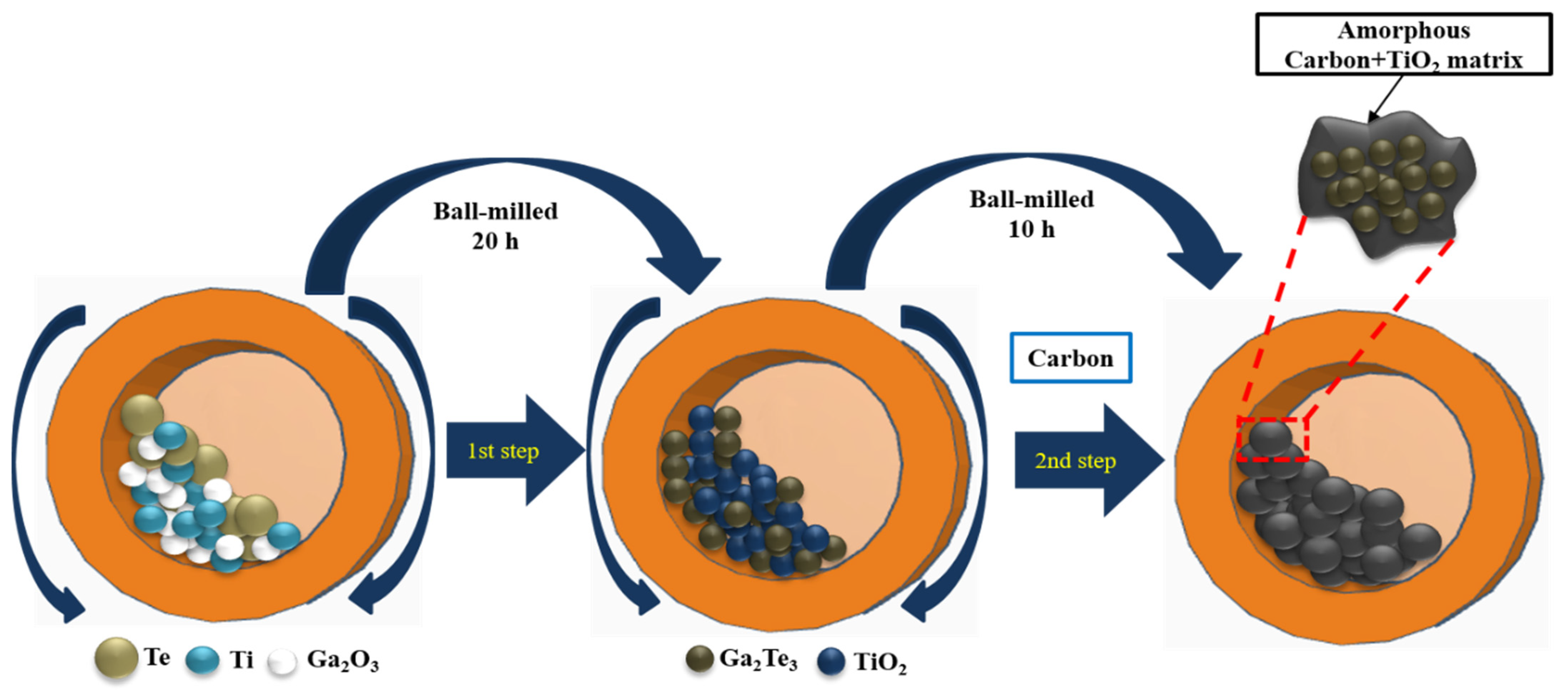
Figure 2.
(a) XRD pattern of Ga2Te3-TiO2; (b) XPS survey spectrum; (c) high-resolution XP spectra of Ga 3d; (d) Te 3d; (e) Ti 2p; (f) O 1 s and (g) C 1 s for Ga2Te3-TiO2-C (10%).
Figure 2.
(a) XRD pattern of Ga2Te3-TiO2; (b) XPS survey spectrum; (c) high-resolution XP spectra of Ga 3d; (d) Te 3d; (e) Ti 2p; (f) O 1 s and (g) C 1 s for Ga2Te3-TiO2-C (10%).
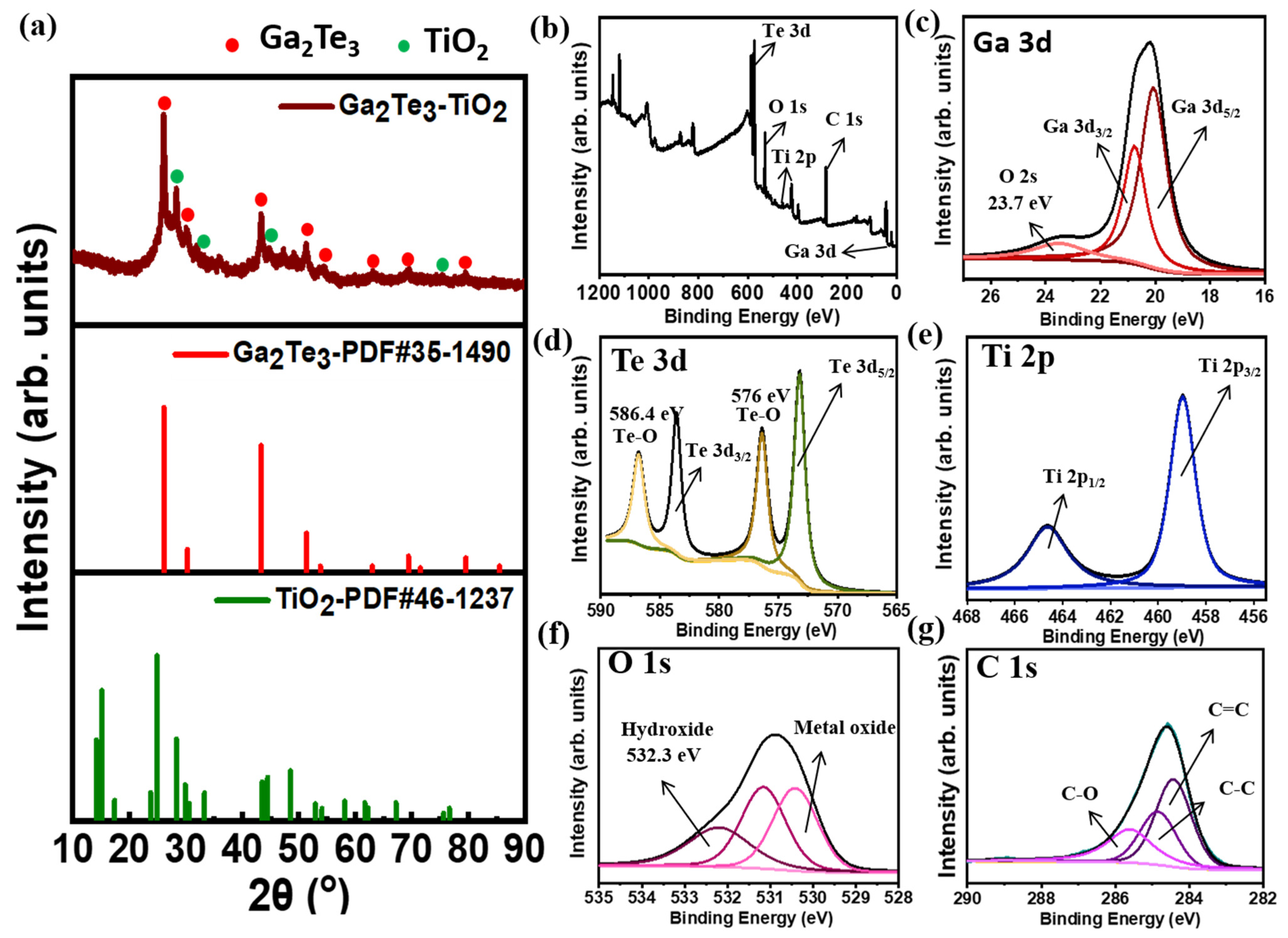
Figure 3.
(a) SEM image; (b) particle size distribution; (c) HRTEM image and (d) EDXS elemental mappings of Ga, Te, Ti, O, and C for Ga2Te3-TiO2-C (10%).
Figure 3.
(a) SEM image; (b) particle size distribution; (c) HRTEM image and (d) EDXS elemental mappings of Ga, Te, Ti, O, and C for Ga2Te3-TiO2-C (10%).
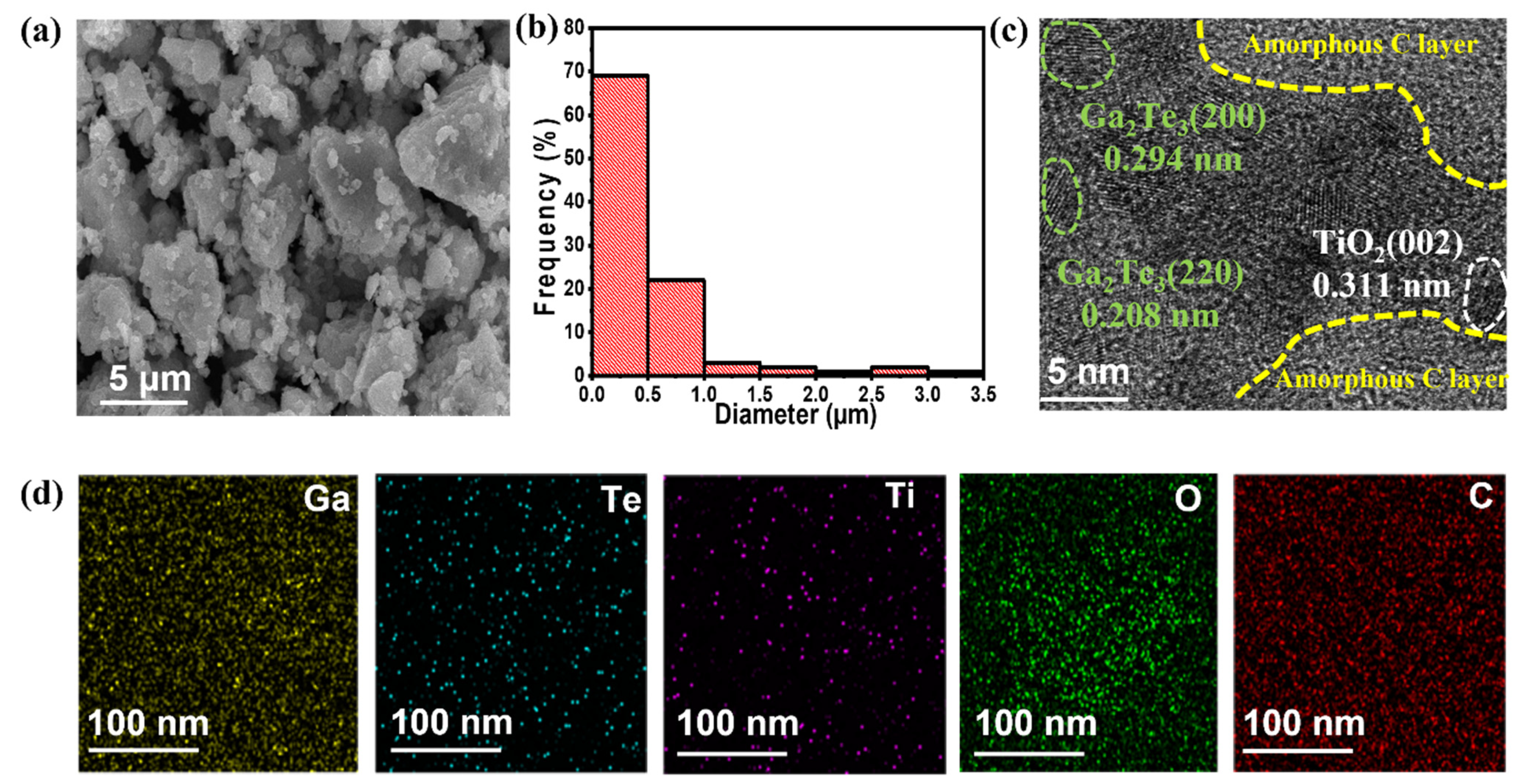
Figure 4.
Electrochemical performance of Ga2Te3-TiO2-C composites for LIBs: (a) GCD curves of Ga2Te3-TiO2-C (10%) at 100 mA g−1; (b) cycling performance of Ga2Te3-TiO2-C composites at 100 mA g−1 and (c) 500 mA g−1; (d) CV curves of Ga2Te3-TiO2-C (10%); (e) rate capabilities of Ga2Te3-TiO2-C composites; and (f) capacity retention of Ga2Te3-TiO2-C composites from 0.1 to 10 A g−1.
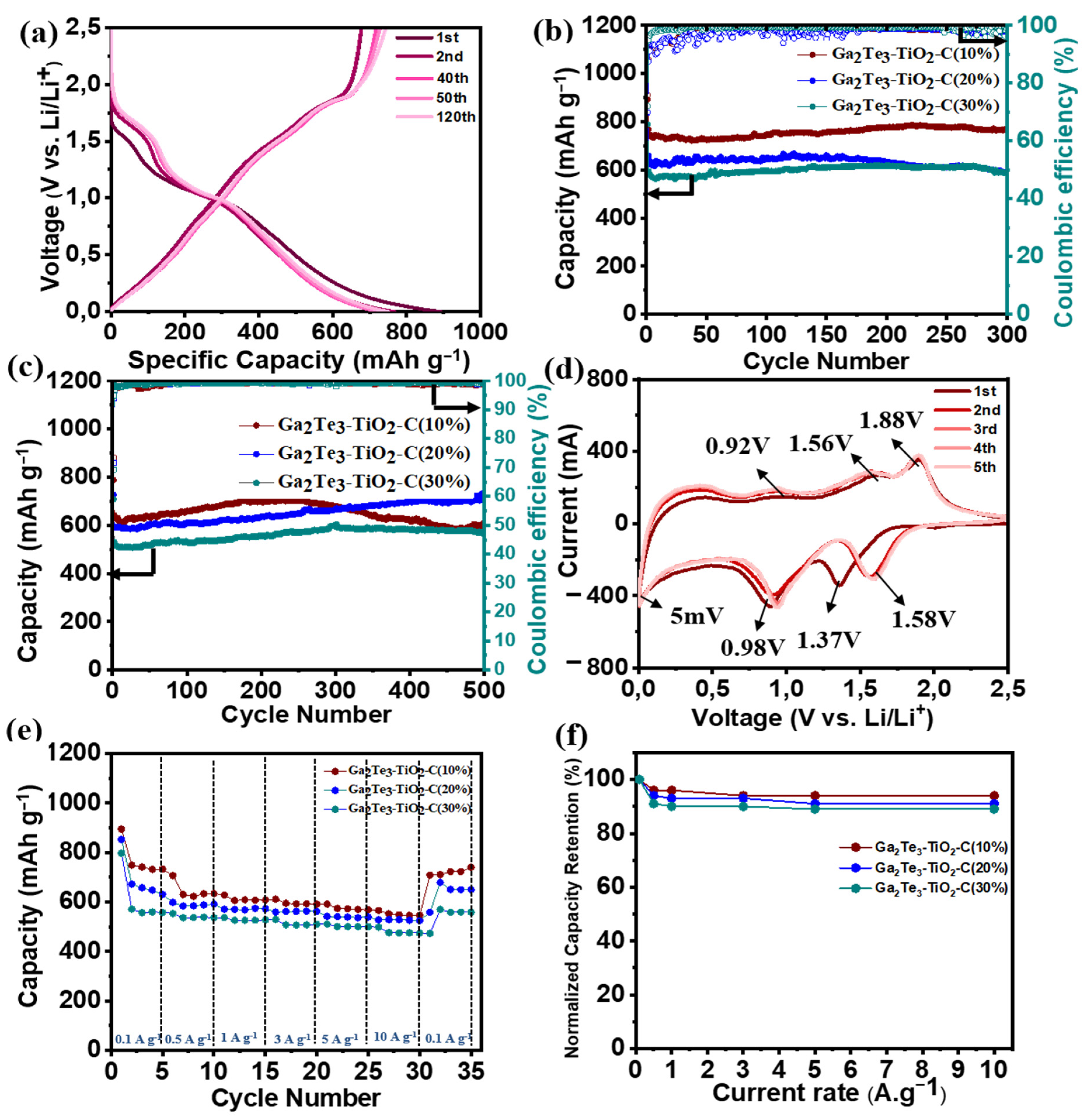
Figure 5.
(a,b) Ex situ XRD patterns obtained at selected cutoff potentials in the initial discharge/charge process, and (c) schematics of phase change of Ga2Te3-TiO2-C (10%) electrode during cycling.
Figure 5.
(a,b) Ex situ XRD patterns obtained at selected cutoff potentials in the initial discharge/charge process, and (c) schematics of phase change of Ga2Te3-TiO2-C (10%) electrode during cycling.
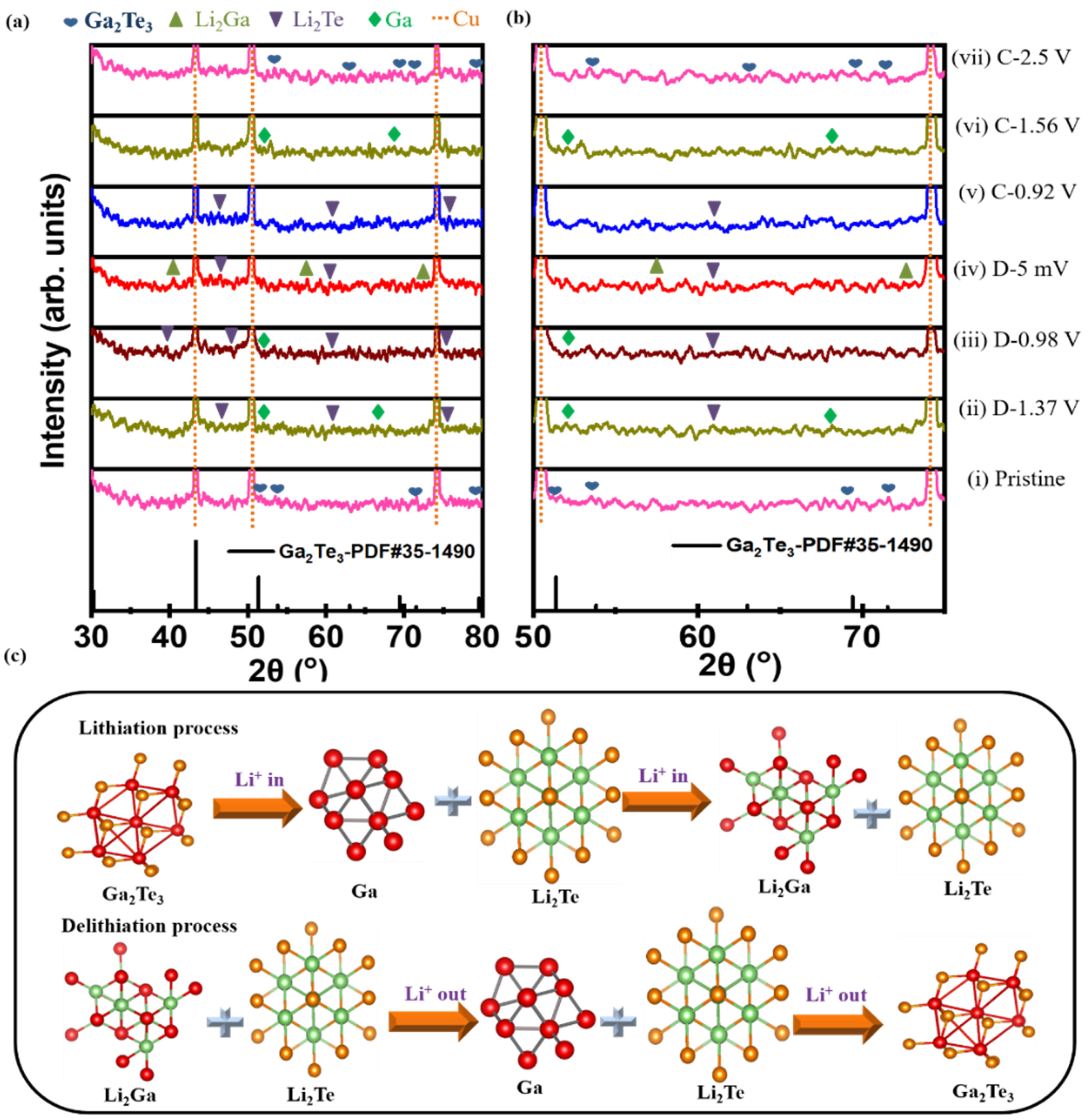
Figure 6.
EIS-based Nyquist plots for (a) Ga2Te3-TiO2-C (10%), (b) Ga2Te3-TiO2-C (20%), (c) Ga2Te3-TiO2-C (30%) after 1, 5, and 20 cycles; and (d) equivalent circuit.
Figure 6.
EIS-based Nyquist plots for (a) Ga2Te3-TiO2-C (10%), (b) Ga2Te3-TiO2-C (20%), (c) Ga2Te3-TiO2-C (30%) after 1, 5, and 20 cycles; and (d) equivalent circuit.
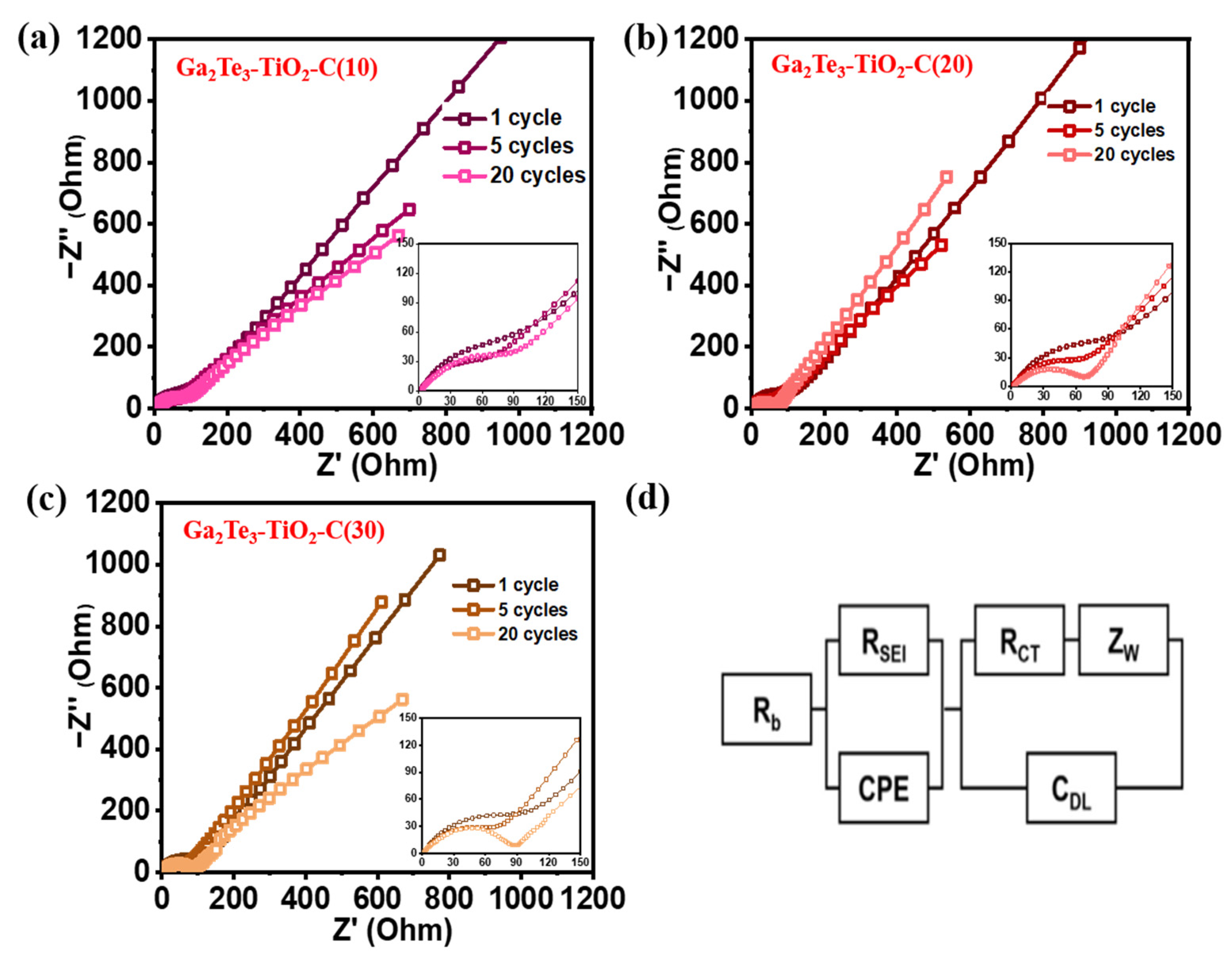
Figure 7.
Schematic of reaction mechanism of Ga2Te3-TiO2-C (10%).

Table 1.
Performances of Ga-based intermetallic electrode for LIBs.
| Anode | Cycling Performance | Rate Capability | Synthesis Method | Ref. |
|---|---|---|---|---|
| GaN-CNFs | 405 mAh g−1 after 1200 cycles at 3 A g−1 | 310 mAh g−1 at 5 A g−1 | Electrospinning | [95] |
| α-Ga2O3@G | 350 mAh g−1 after 50 cycles at 0.15 A g−1 | 344 mAh g−1 at 0.5 A g−1 | Hydrothermal and sintering process | [96] |
| Ga2O3/rGO | 411 mAh g−1 after 600 cycles at 1 A g−1 | 222 mAh g−1 at 2 A g−1 | Sol–gel method | [97] |
| Ga2O3/C | 542 mAh g−1 after 200 cycles at 1 A g−1 | 192 mAh g−1 at 5 A g−1 | One-step hydrogen reduction | [98] |
| Ga-Ni | 420 mAh g−1 after 500 cycles at 3 C | 410 mAh g−1 at 5C | Heating process | [99] |
| CuGa2 | 510 mAh g−1 after 65 cycles at 2 A g−1 | 440 mAh g−1 at 4 A g−1 | Painting liquid Ga onto Cu foil | [100] |
| GaN/G | 600 mAh g−1 after 1000 cycles at 1 A g−1 | 200 mAh g−1 at 10 A g−1 | Wet chemical method | [101] |
| Ga2O3 NPs | 721 mAh g−1 after 200 cycles at 0.5 A g−1 | 280 mAh g−1 at 2 A g−1 | Hydrothermal carbonization method | [102] |
| Ga2S3 | 400 mAh g−1 after 20 cycles at 0.1 A g−1 | - | Commercial material | [103,104] |
| SWCNT-GaSx | 590 mAh g−1 after 100 cycles at 0.6 A g−1 | - | Atomic layer deposition | [105] |
| GaSe | 760 mAh g−1 after 50 cycles at 0.1 A g−1 | 450 mAh g−1 at 5 A g−1 | Chemical reduction method | [106] |
| Ball-milled Ga2Te3/C | 590 mAh g−1 after 500 cycles at 0.1 A g−1 | 495 mAh g−1 at 1C | Ball milling | [107] |
| Ga2Te3-TiO2-C | 769 mAh g−1 after 300 cycles at 0.1 A g−1 | 600 mAh g−1 at 10 Ag−1 | Ball milling | This work |
Publisher’s Note: MDPI stays neutral with regard to jurisdictional claims in published maps and institutional affiliations. |
© 2022 by the authors. Licensee MDPI, Basel, Switzerland. This article is an open access article distributed under the terms and conditions of the Creative Commons Attribution (CC BY) license (https://creativecommons.org/licenses/by/4.0/).
Share and Cite
MDPI and ACS Style
Hoang Huy, V.P.; Kim, I.T.; Hur, J. Gallium-Telluride-Based Composite as Promising Lithium Storage Material. Nanomaterials 2022, 12, 3362. https://doi.org/10.3390/nano12193362
AMA Style
Hoang Huy VP, Kim IT, Hur J. Gallium-Telluride-Based Composite as Promising Lithium Storage Material. Nanomaterials. 2022; 12(19):3362. https://doi.org/10.3390/nano12193362
Chicago/Turabian StyleHoang Huy, Vo Pham, Il Tae Kim, and Jaehyun Hur. 2022. "Gallium-Telluride-Based Composite as Promising Lithium Storage Material" Nanomaterials 12, no. 19: 3362. https://doi.org/10.3390/nano12193362
Note that from the first issue of 2016, this journal uses article numbers instead of page numbers. See further details here.