Effect of Hybrid Carbon Fillers on the Electrical and Morphological Properties of Polystyrene Nanocomposites in Microinjection Molding


Abstract
1. Introduction
2. Materials and Methods
2.1. Materials
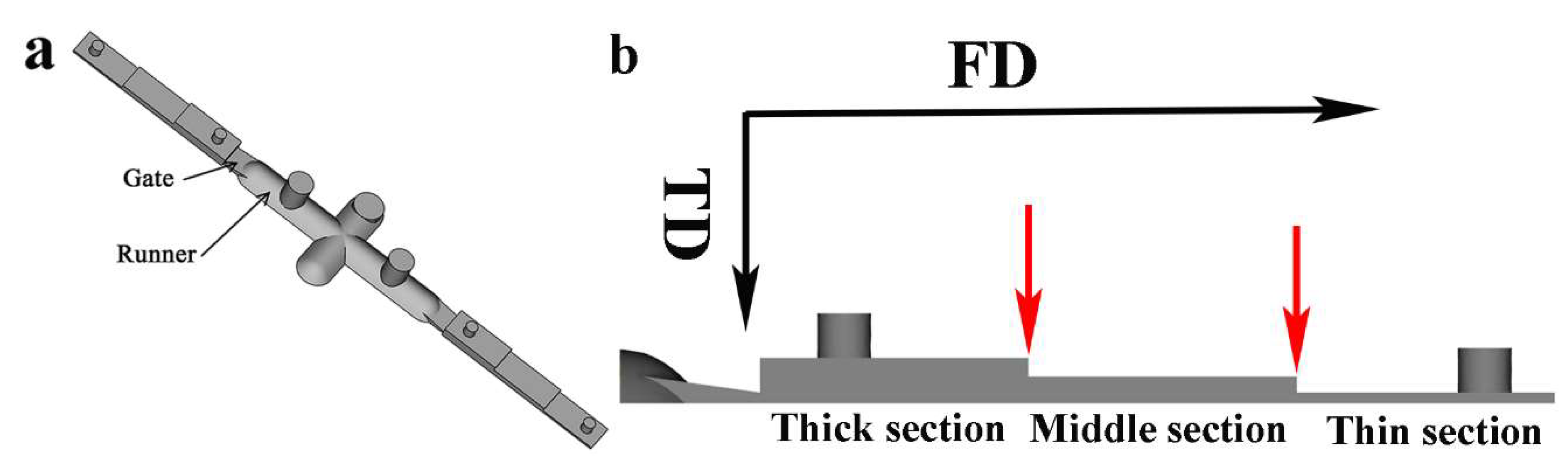
2.2. Preparation of Microparts
2.3. Characterizations
2.3.1. Electrical Conductivity
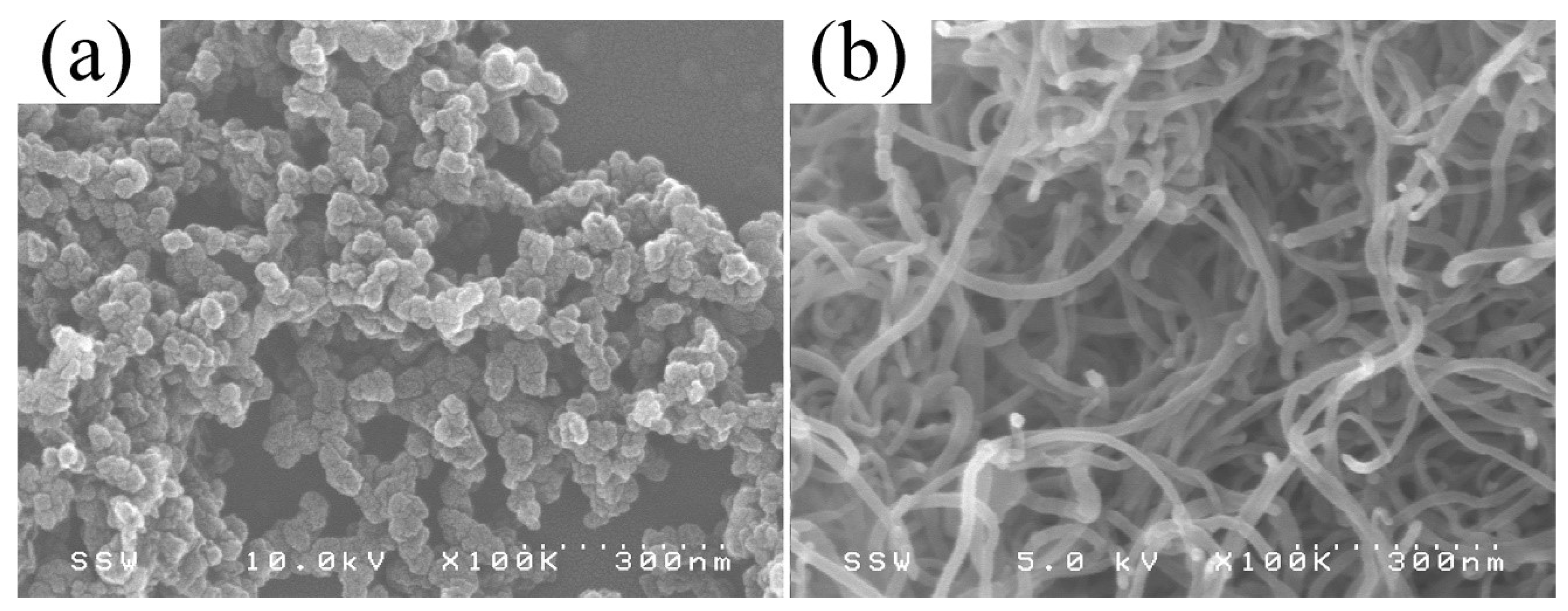
2.3.2. Morphology
3. Results and Discussion
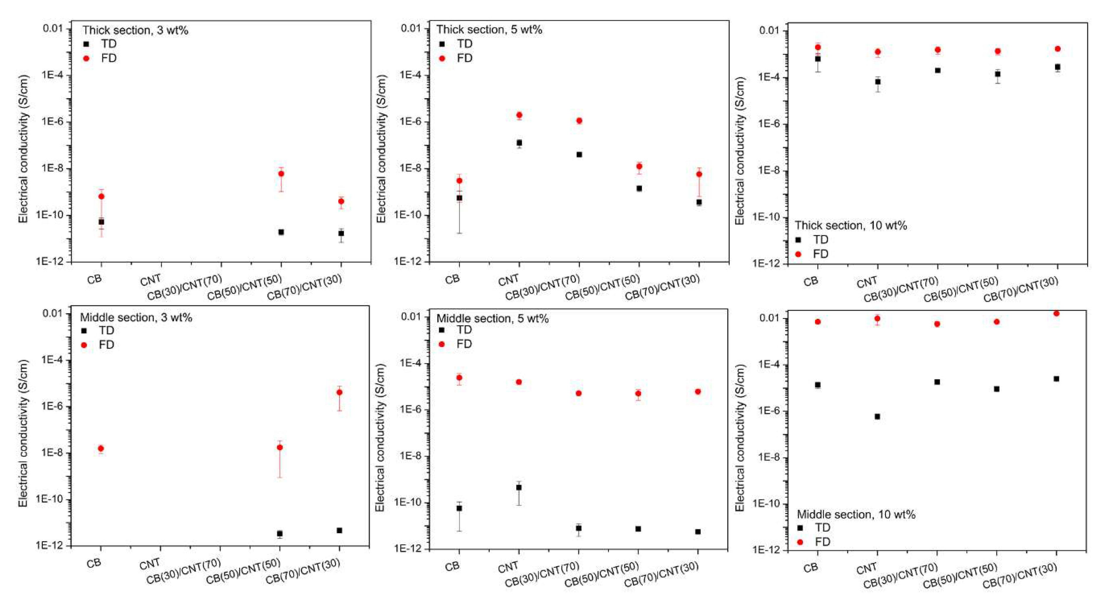
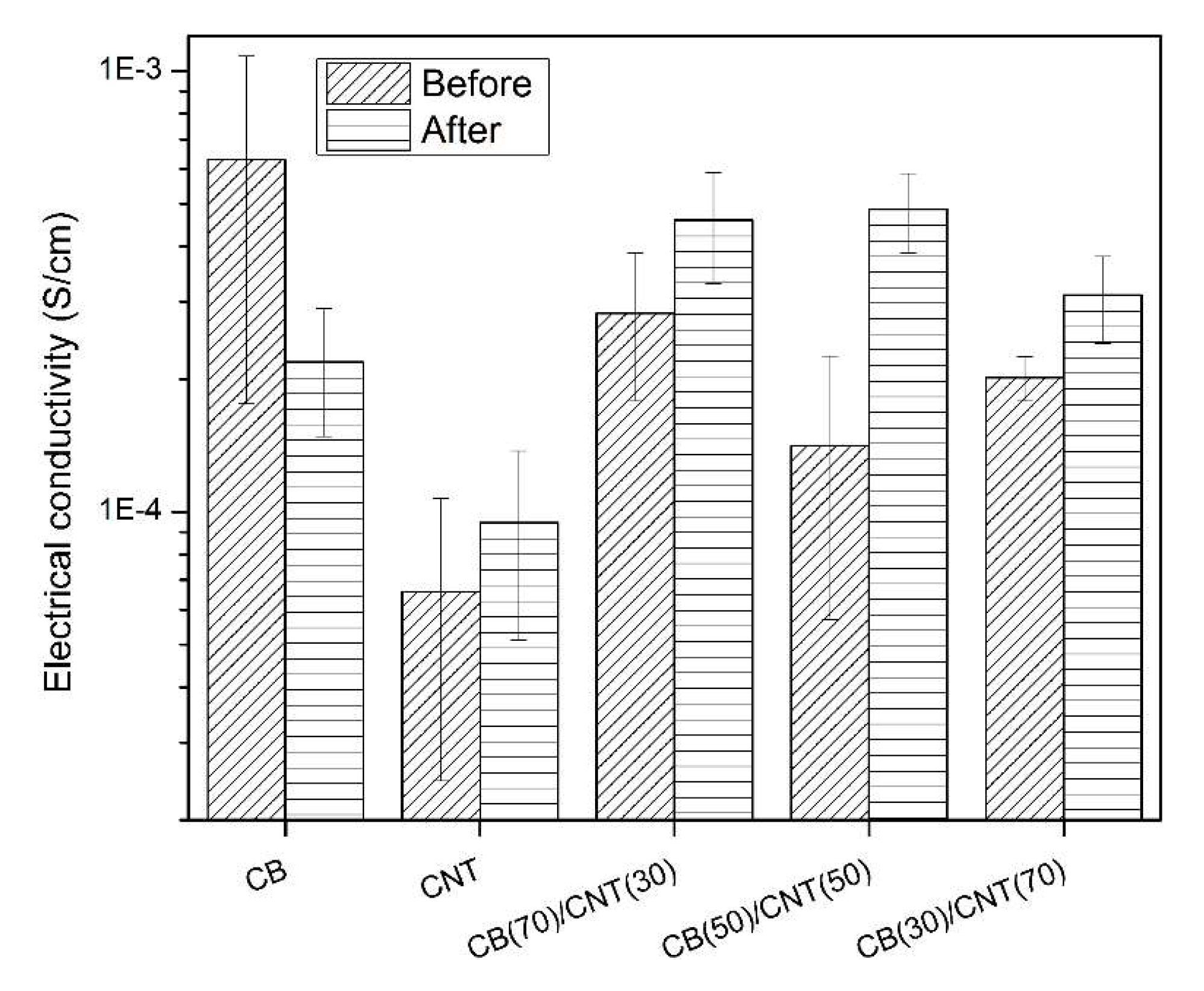
3.1. Electrical Conductivity
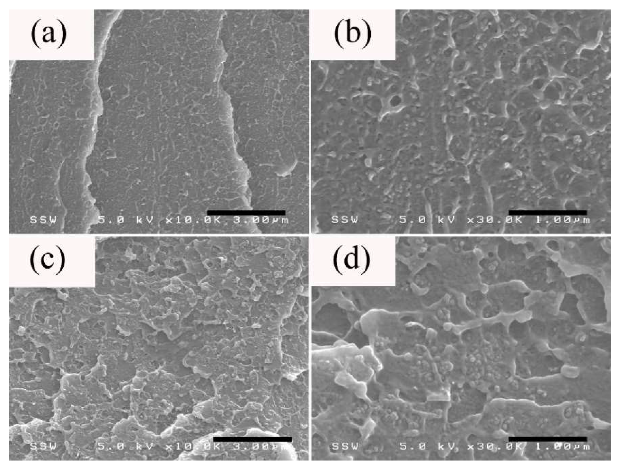
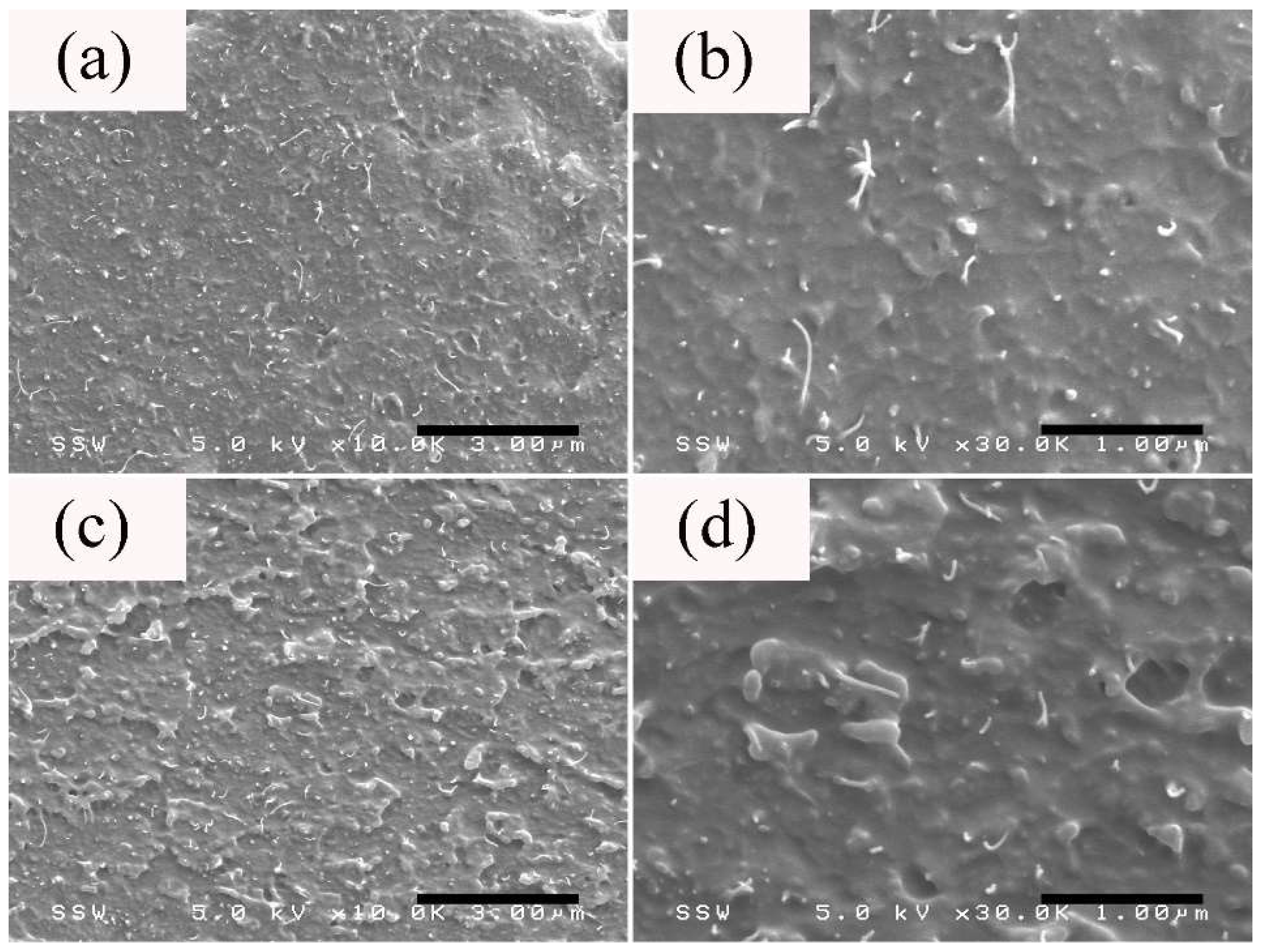
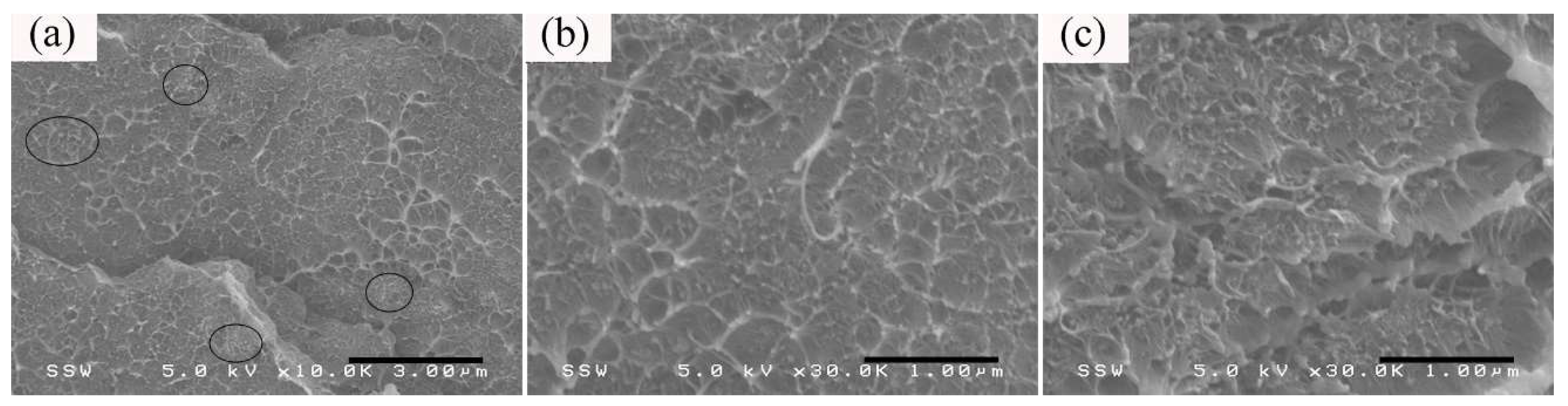
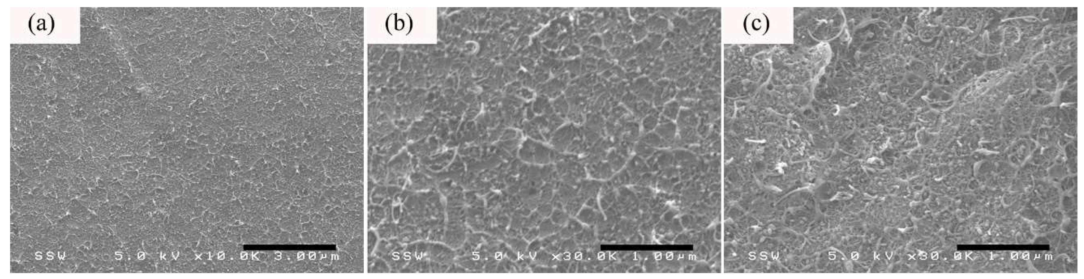
3.2. Morphology
4. Conclusions
Author Contributions
Funding
Conflicts of Interest
References
- Zhang, S.M.; Lin, L.; Deng, H.; Gao, X.; Bilotti, E.; Peijs, T.; Zhang, Q.; Fu, Q. Synergistic effect in conductive networks constructed with carbon nanofillers in different dimensions. Express Polym. Lett. 2012, 6, 159–168. [Google Scholar] [CrossRef]
- Yang, S.Y.; Lin, W.N.; Huang, Y.L.; Tien, H.W.; Wang, J.Y.; Ma, C.C.M.; Li, S.M.; Wang, Y.S. Synergetic effects of graphene platelets and carbon nanotubes on the mechanical and thermal properties of epoxy composites. Carbon 2011, 49, 793–803. [Google Scholar] [CrossRef]
- Etika, K.C.; Liu, L.; Hess, L.A.; Grunlan, J.C. The influence of synergistic stabilization of carbon black and clay on the electrical and mechanical properties of epoxy composites. Carbon 2009, 47, 3128–3136. [Google Scholar] [CrossRef]
- Arjmand, M.; Mahmoodi, M.; Gelves, G.A.; Park, S.; Sundararaj, U. Electrical and electromagnetic interference shielding properties of flow-induced oriented carbon nanotubes in polycarbonate. Carbon 2011, 49, 3430–3440. [Google Scholar] [CrossRef]
- Zhou, S.; Chen, Y.; Zou, H.; Liang, M. Thermally conductive composites obtained by flake graphite filling immiscible Polyamide 6/Polycarbonate blends. Thermochim. Acta 2013, 566, 84–91. [Google Scholar] [CrossRef]
- Zhou, S.; Yu, L.; Song, X.; Chang, J.; Zou, H.; Liang, M. Preparation of highly thermally conducting polyamide 6/graphite composites via low-temperature in situ expansion. J. Appl. Polym. Sci. 2014, 131, 39596. [Google Scholar] [CrossRef]
- Tang, W.; Santare, M.H.; Advani, S.G. Melt processing and mechanical property characterization of multi-walled carbon nanotube/high density polyethylene (MWNT/HDPE) composite films. Carbon 2003, 41, 2779–2785. [Google Scholar] [CrossRef]
- Zhou, S.; Hrymak, A.N.; Kamal, M.R. Microinjection molding of polypropylene/multi-walled carbon nanotube nanocomposites: The influence of process parameters. Polym. Eng. Sci. 2018, 58, E226–E234. [Google Scholar] [CrossRef]
- Bauhofer, W.; Kovacs, J.Z. A review and analysis of electrical percolation in carbon nanotube polymer composites. Compos. Sci. Technol. 2009, 69, 1486–1498. [Google Scholar] [CrossRef]
- Ma, P.C.; Siddiqui, N.A.; Marom, G.; Kim, J.K. Dispersion and functionalization of carbon nanotubes for polymer-based nanocomposites: A review. Compos. Part A Appl. Sci. Manuf. 2010, 41, 1345–1367. [Google Scholar] [CrossRef]
- Shen, L.; Wang, F.Q.; Yang, H.; Meng, Q.R. The combined effects of carbon black and carbon fiber on the electrical properties of composites based on polyethylene or polyethylene/polypropylene blend. Polym. Test. 2011, 30, 442–448. [Google Scholar] [CrossRef]
- Liang, G.D.; Bao, S.P.; Tjong, S.C. Microstructure and properties of polypropylene composites filled with silver and carbon nanotube nanoparticles prepared by melt-compounding. Mater. Sci. Eng. B 2007, 142, 55–61. [Google Scholar] [CrossRef]
- Chu, J.; Kamal, M.R.; Derdouri, S.; Hrymak, A. Characterization of the microinjection molding process. Polym. Eng. Sci. 2010, 50, 1214–1225. [Google Scholar] [CrossRef]
- Giboz, J.; Copponnex, T.; Mélé, P. Microinjection molding of thermoplastic polymers: A review. J. Micromech. Microeng. 2007, 17, R96–R109. [Google Scholar] [CrossRef]
- Ferreira, T.; Lopes, P.E.; Pontes, A.J.; Paiva, M.C. Microinjection molding of polyamide 6. Polym. Adv. Technol. 2014, 25, 891–895. [Google Scholar] [CrossRef]
- Giboz, J.; Spoelstra, A.B.; Portale, G.; Copponnex, T.; Meijer, H.E.H.; Peters, G.W.M.; Mélé, P. On the origin of the “core-free” morphology in microinjection-molded HDPE. J. Polym. Sci. Part B Polym. Phys. 2011, 49, 1470–1478. [Google Scholar] [CrossRef]
- Zhang, N.; Su, Q.; Choi, S.Y.; Gilchrist, M.D. Effects of gate design and cavity thickness on filling, morphology and mechanical properties of microinjection mouldings. Mater. Des. 2015, 83, 835–847. [Google Scholar] [CrossRef]
- Abbasi, S.; Derdouri, A.; Carreau, P.J. Properties of microinjection molding of polymer multiwalled carbon nanotube conducting composites. Polym. Eng. Sci. 2011, 51, 992–1003. [Google Scholar] [CrossRef]
- Zhou, S.; Hrymak, A.; Kamal, M. Electrical and morphological properties of microinjection molded polypropylene/carbon nanocomposites. J. Appl. Polym. Sci. 2017, 134, 45462. [Google Scholar] [CrossRef]
- Chavan, V.; Anandraj, J.; Joshi, G.M.; Cuberes, M.T. Structure, morphology and electrical properties of graphene oxide: CuBis reinforced polystyrene hybrid nanocomposites. J. Mater. Sci. Mater. Electron. 2017, 28, 16415–16425. [Google Scholar] [CrossRef]
- Patole, A.S.; Patole, S.P.; Jung, S.Y.; Yoo, J.B.; An, J.H.; Kim, T.H. Self assembled graphene/carbon nanotube/polystyrene hybrid nanocomposite by in situ microemulsion polymerization. Eur. Polym. J. 2012, 48, 252–259. [Google Scholar] [CrossRef]
- Zhang, B.; Fu, R.; Zhang, M.; Dong, X.; Zhao, B.; Wang, L.; Pittman, C.U., Jr. Studies of the vapor-induced sensitivity of hybrid composites fabricated by filling polystyrene with carbon black and carbon nanotubes. Compos. Part A Appl. Sci. Manuf. 2006, 37, 1884–1889. [Google Scholar] [CrossRef]
- Kamal, M.R.; El Otmani, R.; Derdouri, A.; Chu, J.S. Flow and thermal history effects on morphology and tensile behavior of poly(oxymethylene) micro injection molded parts. Int. Polym. Process. 2017, 32, 590–605. [Google Scholar] [CrossRef]
- López Gaxiola, D.; Jubinski, M.M.; Keith, J.M.; King, J.A.; Miskioglu, I. Effects of carbon fillers on tensile and flexural properties in polypropylene-based resins. J. Appl. Polym. Sci. 2010, 118, 1620–1633. [Google Scholar] [CrossRef]
- Motaghi, A.; Hrymak, A.; Motlagh, G.H. Electrical conductivity and percolation threshold of hybrid carbon/polymer composites. J. Appl. Polym. Sci. 2015, 132, 41744. [Google Scholar] [CrossRef]
- Mavridis, H.; Hrymak, A.N.; Vlachopoulos, J. The Effect of fountain flow on molecular orientation in injection molding. J. Rheol. 1988, 32, 639–663. [Google Scholar] [CrossRef]
- Zhou, S.; Hrymak, A.N.; Kamal, M.R. Electrical and morphological properties of microinjection molded polystyrene/multiwalled carbon nanotubes nanocomposites. Polym. Eng. Sci. 2016, 56, 1182–1190. [Google Scholar] [CrossRef]
- Zamani, M.M.; Fereidoon, A.; Sabet, A. Multi-walled carbon nanotube-filled polypropylene nanocomposites: High velocity impact response and mechanical properties. Iran. Polym. J. 2012, 21, 887–894. [Google Scholar] [CrossRef]
- Jiang, Z.; Chen, Y.; Liu, Z. The morphology, crystallization and conductive performance of a polyoxymethylene/carbon nanotube nanocomposite prepared under microinjection molding conditions. J. Polym. Res. 2014, 21, 451. [Google Scholar] [CrossRef]
- Abbasi, S.; Carreau, P.J.; Derdouri, A. Flow induced orientation of multiwalled carbon nanotubes in polycarbonate nanocomposites: Rheology, conductivity and mechanical properties. Polymer 2010, 51, 922–935. [Google Scholar] [CrossRef]
- Arjmand, M.; Apperley, T.; Okoniewski, M.; Sundararaj, U. Comparative study of electromagnetic interference shielding properties of injection molded versus compression molded multi-walled carbon nanotube/polystyrene composites. Carbon 2012, 50, 5126–5134. [Google Scholar] [CrossRef]
- Ma, P.C.; Liu, M.Y.; Zhang, H.; Wang, S.Q.; Wang, R.; Wang, K.; Wong, Y.K.; Tang, B.Z.; Hong, S.H.; Paik, K.W.; et al. Enhanced electrical conductivity of nanocomposites containing hybrid fillers of carbon nanotubes and carbon black. ACS Appl. Mater. Interfaces 2009, 1, 1090–1096. [Google Scholar] [CrossRef] [PubMed]
- Dang, Z.M.; Shehzad, K.; Zha, J.W.; Mujahid, A.; Hussain, T.; Nie, J.; Shi, C.Y. Complementary percolation characteristics of carbon fillers based electrically percolative thermoplastic elastomer composites. Compos. Sci. Technol. 2011, 72, 28–35. [Google Scholar] [CrossRef]
- Clingerman, M.L.; Weber, E.H.; King, J.A.; Schulz, K.H. Development of an additive equation for predicting the electrical conductivity of carbon-filled composites. J. Appl. Polym. Sci. 2003, 88, 2280–2299. [Google Scholar] [CrossRef]
- Mamunya, E.P.; Davidenko, V.V.; Lebedev, E.V. Effect of polymer-filler interface interactions on percolation conductivity of thermoplastics filled with carbon black. Compos. Interfaces 1996, 4, 169–176. [Google Scholar] [CrossRef]
- Al-Saleh, M.H.; Sundararaj, U. Electromagnetic interference (EMI) shielding effectiveness of PP/PS polymer blends containing high structure carbon black. Macromol. Mater. Eng. 2008, 293, 621–630. [Google Scholar] [CrossRef]
- Chandavasu, C.; Xanthos, M.; Sirkar, K.K.; Gogos, C.C. Polypropylene blends with potential as materials for microporous membranes formed by melt processing. Polymer 2002, 43, 781–795. [Google Scholar] [CrossRef]
- Barber, A.H.; Cohen, S.R.; Daniel Wagner, H. Static and dynamic wetting measurements of single carbon nanotubes. Phys. Rev. Lett. 2004, 92, 186103. [Google Scholar] [CrossRef] [PubMed]
- Zhou, S.; Hrymak, A.N.; Kamal, M.R. Electrical, morphological and thermal properties of microinjection molded polyamide6/multi-walled carbon nanotubes nanocomposites. Compos. Part A Appl. Sci. Manuf. 2017, 103, 84–95. [Google Scholar] [CrossRef]
- Szeluga, U.; Kumanek, B.; Trzebicka, B. Synergy in hybrid polymer/nanocarbon composites. A review. Compos. Part A Appl. Sci. Manuf. 2015, 73, 204–231. [Google Scholar] [CrossRef]
- Motlagh, G.H.; Hrymak, A.N.; Thompson, M.R. Properties of a carbon filled cyclic olefin copolymer. J. Polym. Sci. Part B Polym. Phys. 2007, 45, 1808–1820. [Google Scholar] [CrossRef]
- Wei, T.; Song, L.; Zheng, C.; Wang, K.; Yan, J.; Shao, B.; Fan, Z.J. The synergy of a three filler combination in the conductivity of epoxy composites. Mater. Lett. 2010, 64, 2376–2379. [Google Scholar] [CrossRef]
- Sumfleth, J.; Adroher, X.C.; Schulte, K. Synergistic effects in network formation and electrical properties of hybrid epoxy nanocomposites containing multi-wall carbon nanotubes and carbon black. J. Mater. Sci. 2009, 44, 3241–3247. [Google Scholar] [CrossRef]
- Zhou, S.; Hrymak, A.N.; Kamal, M.R. Microinjection molding of multiwalled carbon nanotubes (CNT)–filled polycarbonate nanocomposites and comparison with electrical and morphological properties of various other CNT-filled thermoplastic micromoldings. Polym. Adv. Technol. 2018, 29, 1753–1764. [Google Scholar] [CrossRef]
- Liang, G.D.; Tjong, S.C. Electrical properties of percolative polystyrene/carbon nanofiber composites. IEEE Trans. Dielectr. Electr. Insul. 2008, 15, 214–220. [Google Scholar] [CrossRef]
- Fei, G.; Tuinea-Bobe, C.; Li, D.; Li, G.; Whiteside, B.; Coates, P.; Xia, H. Electro-activated surface micropattern tuning for microinjection molded electrically conductive shape memory polyurethane composites. RSC Adv. 2013, 3, 24132–24139. [Google Scholar] [CrossRef]
- Li, D.; Fei, G.; Xia, H.; Spencer, P.E.; Coates, P.D. Micro-contact reconstruction of adjacent carbon nanotubes in polymer matrix through annealing-induced relaxation of interfacial residual stress and strain. J. Appl. Polym. Sci. 2015, 132, 42416. [Google Scholar] [CrossRef]
- Pan, Y.; Cheng, H.K.F.; Li, L.; Chan, S.H.; Zhao, J.; Juay, Y.K. Annealing induced electrical conductivity jump of multi-walled carbon nanotube/polypropylene composites and influence of molecular weight of polypropylene. J. Polym. Sci. Part B Polym. Phys. 2010, 48, 2238–2247. [Google Scholar] [CrossRef]
- Alig, I.; Pötschke, P.; Lellinger, D.; Skipa, T.; Pegel, S.; Kasaliwal, G.R.; Villmow, T. Establishment, morphology and properties of carbon nanotube networks in polymer melts. Polymer 2012, 53, 4–28. [Google Scholar] [CrossRef]
- Yui, H.; Wu, G.; Sano, H.; Sumita, M.; Kino, K. Morphology and electrical conductivity of injection-molded polypropylene/carbon black composites with addition of high-density polyethylene. Polymer 2006, 47, 3599–3608. [Google Scholar] [CrossRef]
- Jana, S.C. Loss of surface and volume electrical conductivities in polymer compounds due to shear-induced migration of conductive particles. Polym. Eng. Sci. 2003, 43, 570–579. [Google Scholar] [CrossRef]
- Hong, C.M.; Kim, J.; Jana, S.C. Shear-induced migration of conductive fillers in injection molding. Polym. Eng. Sci. 2004, 44, 2101–2109. [Google Scholar] [CrossRef]
- Navas, I.O.; Arjmand, M.; Sundararaj, U. Effect of carbon nanotubes on morphology evolution of polypropylene/polystyrene blends: Understanding molecular interactions and carbon nanotube migration mechanisms. RSC Adv. 2017, 7, 54222–54234. [Google Scholar] [CrossRef]
- Wu, D.; Lv, Q.; Feng, S.; Chen, J.; Chen, Y.; Qiu, Y.; Yao, X. Polylactide composite foams containing carbon nanotubes and carbon black: Synergistic effect of filler on electrical conductivity. Carbon 2015, 95, 380–387. [Google Scholar] [CrossRef]
- Pegel, S.; Pötschke, P.; Petzold, G.; Alig, I.; Dudkin, S.M.; Lellinger, D. Dispersion, agglomeration, and network formation of multiwalled carbon nanotubes in polycarbonate melts. Polymer 2008, 49, 974–984. [Google Scholar] [CrossRef]
- Reidy, R.F.; Simkovich, G. Anomalous electrical behaviour of polymer-carbon composites as a function of temperature. J. Mater. Sci. 1993, 28, 799–804. [Google Scholar] [CrossRef]
- Tiusanen, J.; Vlasveld, D.; Vuorinen, J. Review on the effects of injection moulding parameters on the electrical resistivity of carbon nanotube filled polymer parts. Compos. Sci. Technol. 2012, 72, 1741–1752. [Google Scholar] [CrossRef]


| Sample | (FD/TD)σ | |
|---|---|---|
| Thick Section | Middle Section | |
| PS/CB 3 wt % | 12.6 | N/A |
| PS/CB 5 wt % | 5.6 | 4.3 × 10⁵ |
| PS/CB 10 wt % | 3.2 | 527 |
| γ | ||||
|---|---|---|---|---|
| mN/m | mN/m | mN/m | mN/m | |
| PS a) | 23.44 | 23.272 | 0.168 | |
| CB b) | 21.77 | 19.59 | 2.18 | |
| CNT c) | 27.8 | 17.6 | 10.2 | |
| PS/CB | 3.29 | |||
| PS/CNT | 11.82 |
| Sample ID | Thick Section-TD (×10−5 S/cm) | Thick Section-FD (×10−5 S/cm) |
|---|---|---|
| PS/CNT 10 wt % | 6.59 | 127 |
| 10 wt %-PS/CNT70/CB30 | 20.2 | 155 |
| 10 wt %-PS/CNT50/CB50 | 14.1 | 137 |
| 10 wt %-PS/CNT30/CB70 | 28.2 | 172 |
| PS/CB 10 wt % | 62.9 | 201 |
© 2018 by the authors. Licensee MDPI, Basel, Switzerland. This article is an open access article distributed under the terms and conditions of the Creative Commons Attribution (CC BY) license (http://creativecommons.org/licenses/by/4.0/).
Share and Cite
Zhou, S.; Hrymak, A.N.; Kamal, M.R. Effect of Hybrid Carbon Fillers on the Electrical and Morphological Properties of Polystyrene Nanocomposites in Microinjection Molding. Nanomaterials 2018, 8, 779. https://doi.org/10.3390/nano8100779
Zhou S, Hrymak AN, Kamal MR. Effect of Hybrid Carbon Fillers on the Electrical and Morphological Properties of Polystyrene Nanocomposites in Microinjection Molding. Nanomaterials. 2018; 8(10):779. https://doi.org/10.3390/nano8100779
Chicago/Turabian StyleZhou, Shengtai, Andrew N. Hrymak, and Musa R. Kamal. 2018. "Effect of Hybrid Carbon Fillers on the Electrical and Morphological Properties of Polystyrene Nanocomposites in Microinjection Molding" Nanomaterials 8, no. 10: 779. https://doi.org/10.3390/nano8100779
APA StyleZhou, S., Hrymak, A. N., & Kamal, M. R. (2018). Effect of Hybrid Carbon Fillers on the Electrical and Morphological Properties of Polystyrene Nanocomposites in Microinjection Molding. Nanomaterials, 8(10), 779. https://doi.org/10.3390/nano8100779