Article

Tailoring of Perpendicular Magnetic Anisotropy in Dy13Fe87 Thin Films with Hexagonal Antidot Lattice Nanostructure

1
Physics Department, Faculty of Science, Sohag University, 82524 Sohag, Egypt
2
Depto. Física, Universidad de Oviedo, C/Federico Garcia Lorca 18, 33007 Oviedo, Asturias, Spain
3
Laboratorio Membranas Nanoporosas, Servicios Científico-Técnicos, Universidad de Oviedo, Campus El Cristo s/n, 33006 Oviedo, Asturias, Spain
4
Instituto de Ciencia de Materiales de Madrid, CSIC, Cantoblanco, 28049 Madrid, Spain
*
Author to whom correspondence should be addressed.
Nanomaterials 2018, 8(4), 227; https://doi.org/10.3390/nano8040227
Submission received: 10 March 2018 / Revised: 31 March 2018 / Accepted: 5 April 2018 / Published: 8 April 2018
(This article belongs to the Special Issue Electrochemically Engineering of Nanoporous Materials)

Abstract

:
In this article, the magnetic properties of hexagonally ordered antidot arrays made of Dy13Fe87 alloy are studied and compared with corresponding ones of continuous thin films with the same compositions and thicknesses, varying between 20 nm and 50 nm. Both samples, the continuous thin films and antidot arrays, were prepared by high vacuum e-beam evaporation of the alloy on the top-surface of glass and hexagonally self-ordered nanoporous alumina templates, which serve as substrates, respectively. By using a highly sensitive magneto-optical Kerr effect (MOKE) and vibrating sample magnetometer (VSM) measurements an interesting phenomenon has been observed, consisting in the easy magnetization axis transfer from a purely in-plane (INP) magnetic anisotropy to out-of-plane (OOP) magnetization. For the 30 nm film thickness we have measured the volume hysteresis loops by VSM with the easy magnetization axis lying along the OOP direction. Using magnetic force microscopy measurements (MFM), there is strong evidence to suggest that the formation of magnetic domains with OOP magnetization occurs in this sample. This phenomenon can be of high interest for the development of novel magnetic and magneto-optic perpendicular recording patterned media based on template-assisted deposition techniques.

Graphical Abstract

1. Introduction

The engineering of magnetic systems based on planar patterned nanostructures by properly controlling the shape and size of the patterned nano-objects allows obtaining magnetic films with non-collinear magnetization distribution, thus enabling the development of magnetic data processing devices with vertical architecture and spin-based electronics [1]. Nanoscale antidot arrays lattices in magnetic materials, i.e., periodic spatial arrangements of nanometric holes in thin metal films, have been studied in a wide scientific and technical scope. Tuned magnetic frustration in spin ice [2,3] and spin glass [4] behavior have been investigated and detected in magnetic nanoscale antidot arrays. The extraordinary features exhibited by these nanostructured materials comes from their relatively large surface to volume ratio, which influences the shape, morphology, crystalline structure, and surface roughness of the material in the nanoscale range [5,6]. These artificial arrays have been recently used in ultra-high density data storage applications [7], where the antidot lattices allow to define a peculiar type of bit patterned media that can overcome the superparamagnetic limit due to the non-formation of isolated magnetic domains [8], in addition to magnetic bio-sensing applications [9], among many others. Moreover, they attract notable attention due to their capacity to act as metamaterials (magnonic crystals), where the antidots exhibit a periodic potential for magnons, allowing for the control of spin wave dispersion [10,11]. The recently reported nanostructured material based on the exchange coupled bicomposite formed by Co. dots embedded in a matrix of NiFe antidot arrays, where the soft ferromagnetic properties of the NiFe antidots influence the vortex nucleation field of Co. dots, can modify the magnetotransport and spin wave properties of the system [12]. Therefore, a wide range of applications in the field of spintronics and spin wave filtering are available by using antidots arrays. The competition between the intrinsic thin film and local shape anisotropies, together with the local effects created by the antidots arrays, generates a new scenario for tailoring the magnetic properties of the thin films by suitably tuning their geometric parameters [13,14]. Furthermore, antidot lattices strongly influence the magnetic properties of the hosting materials and can be used for artificially engineering the magnetic anisotropy and tuning the coercivity in thin films [15]. In this work, we report on the observation of an interesting phenomenon, consisting of the easy magnetization axis transfer from a purely in-plane (INP) magnetic anisotropy to out-of-plane (OOP) magnetization, for a 30 nm thick layer of Dy13Fe87 thin film with hexagonally ordered antidots lattice.

2. Materials and Methods

Experimental Procedure of Sample Fabrication and Characterization

The former patterned film substrate formed by a hexagonally ordered nanoporous alumina membrane was synthesized by following a well-established two-step electrochemical anodization procedure in oxalic acid, as reported elsewhere [16,17]. In brief, 0.5 mm thick, high purity Al foils (99.999%, Goodfellow, Huntingdon, UK) were cleaned by sonication in ethanol and isopropyl alcohols and electropolished at 20 V in perchloric acid and ethanol solution (1:3 vol., 5 °C) for 5 min. The polished Al foils were then employed as starting substrates for the anodic synthesis of nanoporous alumina templates. The two-step electrochemical anodization was performed in 0.3 M oxalic acid, at a temperature of 1–3 °C and under a potentiostatic applied voltage of 40 V, measured versus a Pt counter electrode. Between the two anodization steps, the samples were immersed in 0.2 M CrO3 and 0.6 M H3PO4 aqueous solution. This selective chemical etching step allowed for the selective removal of the first grown anodic alumina layer, which contained randomly disordered nanopores at its top surface. In the second anodization step, which lasted for 5 h, the nanopores grew following a highly self-ordered hexagonal pattern. Afterwards, in order to increase the pore size, the samples were chemically etched in 5 wt % orthophosphoric acid at 30 °C, for 30 min.
The controlled deposition of the metallic alloy formed by highly pure metal pieces of Dy (99.99%) and Fe (99.9%) was completed by a high vacuum thermal evaporation technique using an E306A thermal vacuum coating unit (Edwards, Crawley, UK) with an ultimate vacuum better than 7 × 10⁻⁷ mbar (5.2 × 10⁻⁷ mbar), having a diffusion pump backed by rotary pumping together with a liquid nitrogen trap [18]. The pure element metal pieces were placed inside two water cooled copper crucibles and heated by the action of magnetically focused electron beams. The evaporated target metals were deposited on the top-surface of the hexagonally ordered nanoporous alumina membranes, which acted as templates to obtain the thin film antidot arrays [19]. The control of the film thickness and the alloy composition was achieved by using two independent quartz crystal controllers that monitored simultaneously the deposition rates of both evaporation sources. This equipment allowed for obtaining both the film thickness and final alloy composition from the measurements displayed in both of the quartz crystal control monitors. Each one of these quartz crystal controllers received the evaporation beam coming from a unique evaporation source. The source to substrate distances were maintained constant at about 18 cm. The deposition rate was around 0.1–0.15 nm s−1. The alloy composition was controlled through the quartz crystal control, and the values obtained by this procedure are in good agreement with the ones analyzed by energy dispersive X-ray spectroscopy (EDX) (Inca Energy 200, Oxford Instruments, Abingdon, UK) with a scanning electron microscope (SEM) (JSM 5600, JEOL, Akishima, Tokyo, Japan).
High resolution transmission electron microscopy (HR-TEM) (JEM 2100, JEOL, Akishima, Tokyo, Japan) operating at 200 kV was employed to obtain high magnification images of the antidots thin films, as well as to study their microstructure by performing a selected area electron diffraction (SAED) spectra. For that purpose, the nanoporous alumina membrane that acts as a template for the fabrication of the antidot arrays was previously and selectively dissolved in a 0.5 M NaOH solution, thus releasing freestanding flakes of the nanostructured thin film, which were then washed with distilled water and ethanol, deposited into conventional transmission electron microscopy (TEM) copper grid sample holders and dried in air.
The surface topography and magnetic domain configuration were studied by Atomic Force Microscopy (AFM) and Magnetic Force Microscopy (MFM) measurements, respectively, performed with a Cervantes system from Nanotec Electronica S.L. (Tres Cantos, Madrid, Spain ) in amplitude modulation mode with the Phase Locked Loop (PLL) feedback enabled. Commercial probes from Budget Sensors MagneticMulti75-G, with CoCr coating were used.
The surface magneto-optic properties of the thin film antidot arrays were obtained making use of a scanning laser Magneto-Optical Kerr Effect (MOKE) magnetometer, NanoMOKE3® (Durham Magneto Optics Ltd., Durham, UK), being able to apply up to 0.125 T by using the quadrupole electromagnet option or 0.5 T, with the dipole electromagnet option. The NanoMOKE3 magnetometer is suited with p-polarized laser beam and it is sensitive to the longitudinal, transversal, and polar magneto-optical Kerr effects. Complementary bulk magnetic measurements were carried out by using a vibrating sample magnetometer (VSM-QD-Versalab, San Diego, CA, USA), with applied magnetic fields up to ±3 T at room temperature and in both, parallel (In Plane, INP) and perpendicular (Out of Plane, OOP) directions to the film plane, respectively.

3. Results and Discussion

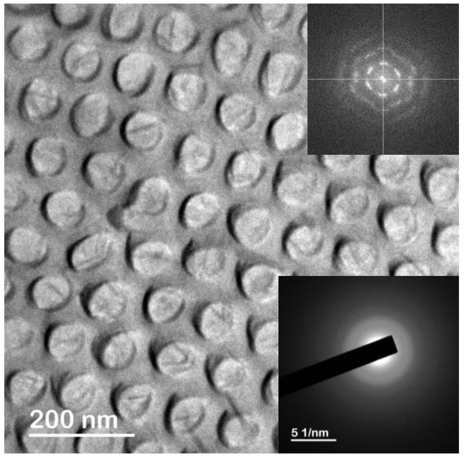
3.1. Scaning Electron Microscopy Analysis

Figure 1a displays the highly ordered, hexagonally centered nanopores of the alumina template after being synthesized by two-step electrochemical anodization in oxalic acid and further pore widening by chemical etching, as explained in detail in the experimental section. The resulting lattice parameters of the so-synthesized nanoporous alumina membrane employed as a starting template for the thin film deposition are around 75 nm of nanopores diameter, dp, and 105 nm of the interpore distance, Dint. Hexagonal-ordered array of Dy13Fe87 antidot thin films having an interpore distance of Dint = 105 nm, hole diameter d = 45 nm, and thickness t = 30 nm, are shown in Figure 1b. The antidot thin film displayed in Figure 1b replicates the same hexagonal nanoholes ordering of the starting nanoporous alumina membrane used as a patterned template, as shown in Figure 1a. Therefore, the antidot array structure exhibits two main distinguished directions [13]: first, the nearest neighbors (nn) direction, which corresponds to the in-plane easy anisotropy axis; and second, the next-nearest neighbors (nnn) direction along which lies the in-plane hard anisotropy axis, at an angle of 30° referred to the previous nn direction (see Figure 1b). Figure 1c shows a 50 nm thick antidot thin film, deposited onto the surface of the patterned nanoporous alumina template as shown in Figure 1a. It becomes evident from the comparison of both SEM images displayed in Figure 1a–c that there is a nearly inversed linear dependence between the diameter of the antidots, d, and the film thickness, t, for a given pore diameter of the nanoporous alumina template, dp. In other words, as the thin film thickness increases, the nanoholes decrease their manifest diameter due to the deposition of hosting material on the top part of the hole wall [20,21].

3.2. Transmission Electron Microscopy Characterization

The TEM micrograph of the Dy13Fe87 antidots thin film after being released from the nanoporous alumina membrane, which is displayed in Figure 2, demonstrates that the nanometric holes successfully replicated the structure of the highly hexagonal ordered nanoporous alumina template, in good agreement with the findings revealed by the SEM images. The Fast Fourier Transform (FFT) shown in the upper inset of Figure 2, which is characteristic of a system with hexagonal periodic symmetry, reinforces this observation. In addition, the SAED spectrum, shown as the lower inset in Figure 2, indicates the amorphous structure of the Dy13Fe87 alloy, evidenced by the presence of diffused rings and the absence of clear spots in the electron diffraction spectrum.

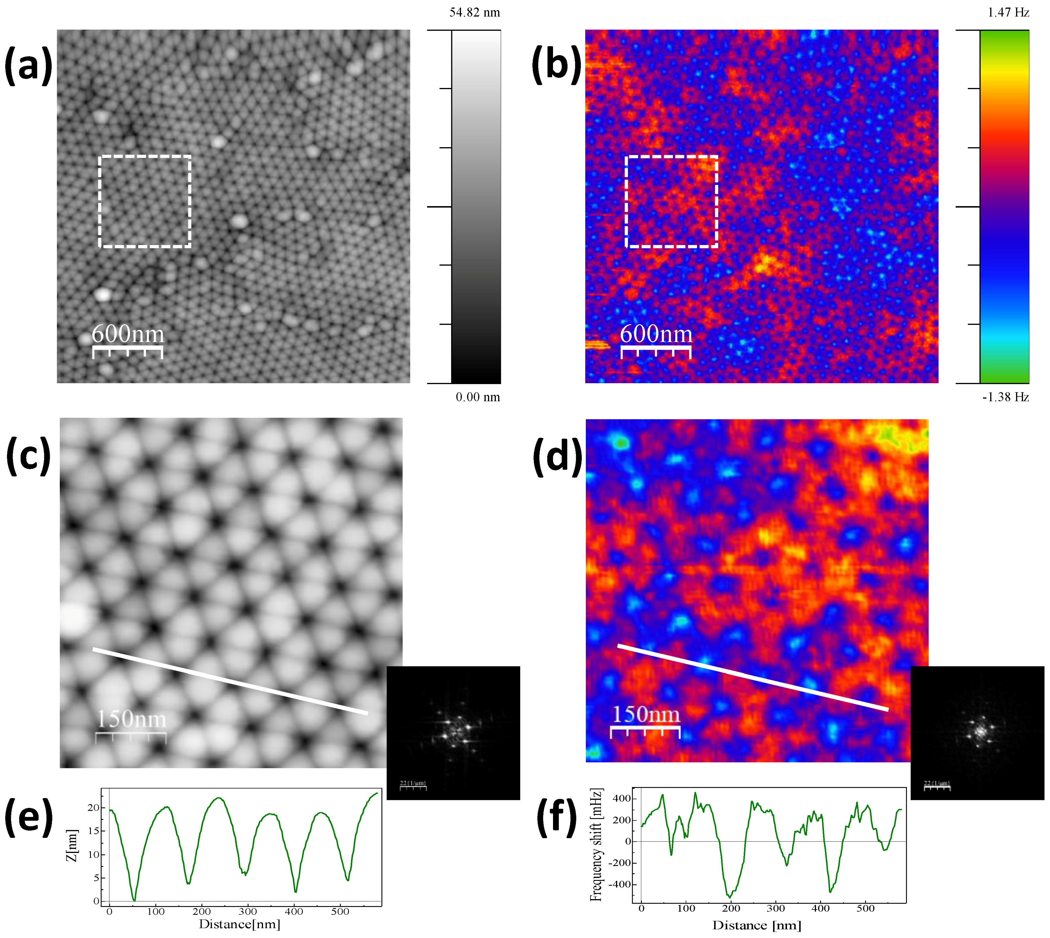
3.3. Atomic Force Microscopy and Magnetic Force Microscopy Imaging

The AFM image of the surface topography of the Dy13Fe87 antidot sample, with thickness of 30 nm, can be observed in Figure 3a. The nanometric hole structure of the magnetic film is clearly visible and replicates the hexagonal geometry of the nanoporous alumina membrane used as template. The MFM signal is mainly sensitive to the out of plane component of the magnetization and to the magnetic-poles accumulation around the domain walls. The MFM image obtained in the same region in the as prepared state (see Figure 3b) presents a magnetic configuration with positive and negative contrast corresponding to the out of plane magnetization. As shown in Figure 3a, the sample presents different morphological domains. Figure 3c,d are the zooms performed in the marked regions in Figure 3a,b, respectively, in order to study the topographic periodicity and its correlation with the magnetic signal. The profiles along the nn direction are displayed in Figure 3e,f. From the profile scan in Figure 3e, as well as from the FFT data shown in the inset, the lattice constant of the hexagonal antidot arrangement is estimated to be around 110 nm, in good agreement with SEM and TEM characterization. The corresponding MFM signal in Figure 3d,f allows us to distinguish the superposition of two kinds of contrast, one correlated with the topographic signal (always negative) and a positive/negative contrast corresponding to the out of plane magnetization, which is not correlated with the holes’ position. Notice that the FFT of the MFM signal presents a set of peaks corresponding to the hexagonal lattice and an additional contrast associated to the larger structures. Such component of the magnetic signal is due to the local magnetic anisotropy induced by the antidot thin film geometry.

3.4. Magneto-Optical Kerr Effect Hysteresis Loops

The surface magnetic properties of the Dy13Fe87 antidot thin films were characterized making use of the MOKE. In the Figure 4a it is represented, in black line, the longitudinal MOKE hysteresis loop of a continuous Dy13Fe87 thin film, with 30 nm in thickness. It shows a square shape that matches with an in-plane easy magnetization axis. Red and blue plots in Figure 4a show the longitudinal MOKE hysteresis loops for 30 nm thick antidot thin film, measured along both, the nn and nnn directions, respectively. By comparison of these two later measurements, we can observe that these directions act as easy (nn) and hard (nnn) in-plane magnetization axes. Furthermore, both longitudinal hysteresis loops for the antidot thin film measured along the in-plane nn and nnn directions have lost the squared shape and acquired a shape bending in slope, if compared with the one from the continuous thin film. This fact shows that the magnetization is not aligned along an easy axis direction, indicating that the easy magnetization axis does not totally lie in the in-plane direction. Coercivity of Dy13Fe87 antidots thin film also noticeably increases with respect to the one for the continuous film, caused by the presence of holes that act as pinning centers of domain wall displacement [15].
Figure 4b shows the hysteresis loop obtained by polar MOKE for the same antidot thin film with an out-of-plane applied magnetic field. In the polar MOKE configuration, the response of the polar Kerr effect is sensitive to the out of plane magnetization signal, while the longitudinal Kerr measurement is sensitive to any magnetization along the intersection of the film surface plane with the incidence plane of the laser beam, and thus the longitudinal Kerr response is dominated by the in-plane magnetization [22]. The hysteresis loop plotted in Figure 4b shows a dominant magnetization component perpendicular to the surface plane in pseudo magnetization saturation. This fact proves the dropping of the magnetization onto the out of plane direction [22].

3.5. Vibrating Sample Magnetometer Hysteresis Loops

The global magnetic behavior of antidots thin film has been investigated by measuring the bulk sample hysteresis loops, employing a VSM, at room temperature and with applied magnetic field values up to ±3 T. Two common magnetic field configurations were considered for the applied magnetic field, in-plane (INP, when the magnetic field is applied parallel to the film plane) and out of plane (OOP, for the magnetic field perpendicularly applied to film plane). Figure 5a shows both, the INP and OOP hysteresis loops for a continuous thin film having 30 nm in thickness and Figure 5b shows the corresponding ones for the antidot thin film with the same thickness.
It can be observed from Figure 5a that the magnetization is laying along the INP direction for the Dy13Fe87 continuous film. In contrast, the OOP magnetization direction for antidot arrays is dominating, as it can be deduced from Figure 5b and confirmed by the polar-MOKE measurement. In addition, it can be observed the INP shape anisotropy deduced for the continuous thin film, while a more complex magnetic structure is ascribed for the antidot thin film, where its OOP component clearly differs from that of the continuous film. Similar magnetic behavior was also detected by J. Gräfe et al. in Fe antidot arrays with hexagonal ordering [23].
It is expected that the magnetic anisotropy contributes to the appearance of the OOP magnetization component. The antidot arrays can induce strong local shape anisotropy. This can overcome any kind of intrinsic anisotropy of the host materials, moreover it prefers an OOP orientation of the magnetization [24]. In addition, theoretical studies about the magnetic anisotropy of antidot arrays performed by Monte Carlo [25] and in micro-magnetic simulations [26] illustrate that the INP preferred orientation of the magnetization in a thin film of antidots array can be, at least partially, lifted. Furthermore, the magnetic surface anisotropy contributes to the partial OOP magnetization found here [27].
The local geometry of antidot plays a major important role on the magnetization reversal of the antidot films [28,29,30,31]. Such kind of nanohole arrays are usually described by a parameter named the antidot aspect ratio, r, which is defined by [32,33]:
r = (d + dp)/2t,
Aiming to further investigate the rise of OOP magnetization phenomena, we have estimated the effective in-plane anisotropy, Keff, for antidots and thin film samples with the same Dy13Fe87 composition and different thicknesses. Keff values were calculated from INP and OOP VSM hysteresis loops according to ref. [29], and they are given by:
K e f f = 4 π [ 0 _ O O P M S H d M 0 _ I N P M S H d M ]
where M is the magnetization, MS is the saturation magnetization and H is the applied magnetic field. These effective anisotropy values obtained for samples with different thickness of the Dy13Fe87 film are given in Table 1, together with the antidot hole diameter and the corresponding aspect ratio.
For the t = 20 nm sample, the aspect ratio, r, takes values of around three, indicating that the antidots display larger diameter than thickness, and therefore, the magnetization preferred direction remains in plane. Nevertheless, the effect of antidots in this sample becomes evident, if we compare the Keff values for 20 nm thick antidot and thin film samples shown in Table 1. The difference in one order of magnitude between them can be ascribed to the competition between INP and OOP anisotropies. In contrast, for the 30 nm thick sample, the aspect ratio is closer to two, that is, the thickness of the thin film is near to the average antidot diameters. Therefore, the magnetostatic energy accumulated by the surface poles, in the film plane, and that due to magnetic poles on the nanohole surfaces starts to be of the same order of magnitude. Thus, the resulting magnetization lies in the OOP direction, as the thickness, t, increases, in order to reduce the whole magnetostatic energy of the system [32,33], leading to a negative value of Keff. Finally, when the film thickness is further increased, the antidot hole diameter is greatly reduced, due to the deposition of material in the pore walls. As a consequence, the antidot film behaves similarly to the continuous thin film, as evidenced by the positive sign of Keff, which takes values of the same order of magnitude than for the continuous thin films.

4. Conclusions

In this work, we report on the transfer of the easy magnetization axis from the in plane, in the case of Dy13Fe87 thin film, to out of plane, for the antidot arrays film with the same thickness condition.
The antidot arrays introduce a drastic change in the morphology and magnetic behavior of the magnetic thin film if we compare it with that one of the continuous thin film. It increases the magnetostatic energy associated to the antidot arrays, if the magnetization lays in the film plane. This energy might be due to the appearance of magnetic poles on the antidot surfaces in competition with the magnetostatic energy due to the magnetic poles on the film surface when the magnetization is OOP. Obviously, the magnetostatic energy associated to the antidot array, increases with the film thickness. When the layer thickness increases well enough to counterbalance the energy associated to the magnetic poles on the film surface, the preferred direction of magnetization should change from INP to OOP direction. This effect has been observed for t = 30 nm, whereas for samples with lower or higher film thickness, the magnetization remains INP, which is ascribed to the high value of antidots aspect ratio and to the reduction in hole size with the increase in layer thickness, respectively.
Additionally, by suitably controlling the antidot aspect ratio parameter, it also allows for tailoring the magnetization process of the magnetic materials and controlling the direction of easy magnetization axis from the in plane or out of plane directions.
Furthermore, the change of INP to an OOP magnetization signal may open up new directions in magnetic sensing or spintronic applications at the nanoscale by combining two devices that need different orientations of the magnetic signal. Finally, the transformation of in-plane magnetic information to an out-of-plane magnetic signal may advance 2D magnetic logic to the third dimension.

Acknowledgments

This work was supported by the Ministerio de Economia y Competitividad (MINECO) from Spain, under grants MAT2013-48054-C2-2-R, MAT2016-76824-C3-1-R and MAT2016-76824-C3-3-R; together with the Principado de Asturias (Spain) under grant FC-15-GRUPIN14-085. M. Jaafar wishes also to acknowledge her funding grant from Spanish MINECO under MAT2015-73775-JIN research project. The scientific support from the SCTs of the University of Oviedo is also gratefully recognized.

Author Contributions

A.F. and V.M.P. conceived and designed the experiments; V.V. synthesized the nanoporous alumina membranes and performed SEM characterization; M.S. and A.F. deposited the antidot thin films; M.S. and V.V. performed the magnetic characterization; A.I., M.J. and A.A. carried out the AFM/MFM studies; M.S., V.M.P. and A.F. analyzed the data. All authors have contributed in co-writing of the manuscript and gave approval to the final revision.

Conflicts of Interest

The authors declare no conflict of interest. The founding sponsors had no role in the design of the study; in the collection, analyses, or interpretation of data; in the writing of the manuscript, and in the decision to publish the results.

References

  1. Stamps, R.L.; Breitkreutz, S.; Akerman, J.; Chumak, A.V.; Otani, Y.; Bauer, G.E.W.; Thiele, J.-U.; Bowen, M.; Majetich, S.A.; Klaui, M.; et al. The 2014 Magnetism Roadmap. J. Phys. D Appl. Phys. 2014, 47, 333001. [Google Scholar] [CrossRef] [Green Version]
  2. Zhang, S.; Gilbert, I.; Nisoli, C.; Chern, G.W.; Erickson, M.J.; O’Brien, L.; Leighton, C.; Lammenrt, P.E.; Crespi, V.H.; Schiffer, P. Crystallites of magnetic charges in artificial spin ice. Nature 2013, 500, 553–557. [Google Scholar] [CrossRef] [PubMed]
  3. Heyderman, L.J. Artificial spin ice: Crystal-clear order. Nat. Nanotechnol. 2013, 8, 705–706. [Google Scholar] [CrossRef] [PubMed]
  4. Laguna, M.F.; Balseiro, C.A.; Domínguez, D.; Nori, F. Vortex structure and dynamics in kagomé and triangular pinning potentials. Phys. Rev. B 2001, 64, 104505. [Google Scholar] [CrossRef]
  5. Abad, A.; Corma, A.; García, H. Supported gold nanoparticles for aerobic, solventless oxidation of allylic alcohols. Pure Appl. Chem. 2007, 79, 1847–1854. [Google Scholar] [CrossRef]
  6. Mengotti, E.; Heyderman, L.J.; Rodriguez, A.F.; Nolting, F.; Hugli, R.V.; Braun, H.B. Real-space observation of emergent magnetic monopoles and associated Dirac strings in artificial kagome spin ice. Nat. Phys. 2011, 7, 68–74. [Google Scholar] [CrossRef]
  7. Ünal, A.A.; Valencia, S.; Radu, F.; Marchenko, D.; Merazzo, K.J.; Vázquez, M.; Sánchez-Barriga, J. Ferrimagnetic DyCo5 Nanostructures for Bits in Heat-Assisted Magnetic Recording. Phys. Rev. Appl. 2016, 5, 064007. [Google Scholar] [CrossRef]
  8. Cowburn, R.P.; Adeyeye, A.O.; Bland, J.A.C. Magnetic domain formation in lithographically defined antidot Permalloy arrays. Appl. Phys. Lett. 1997, 70, 2309–2311. [Google Scholar] [CrossRef]
  9. Metaxas, P.J.; Sushruth, M.; Begley, R.A.; Ding, J.; Woodward, R.C.; Maksymov, I.S.; Albert, M.; Wang, W.; Fangohr, H.; Adeyeye, A.O.; et al. Sensing magnetic nanoparticles using nano-confined ferromagnetic resonances in a magnonic crystal. Appl. Phys. Lett. 2015, 106, 232406. [Google Scholar] [CrossRef]
  10. Yu, H.; Duerr, G.; Huber, R.; Bahr, M.; Schwarze, T.; Brandl, F.; Grundler, D. Omni directional spin-wave nanograting coupler. Nat. Commun. 2013, 4, 2702. [Google Scholar] [CrossRef] [PubMed]
  11. Zhang, W.; Li, J.; Ding, X.; Pernod, P.; Tiercelin, N.; Song, Y. Tunable Magneto-Optical Kerr Effect of Nanoporous Thin Films. Sci. Rep. 2017, 7, 2888. [Google Scholar] [CrossRef] [PubMed]
  12. Coïsson, M.; Federica Celegato, F.; Gabriele Barrera, G.; Gianluca Conta, G.; Alessandro Magni, A.; Paola Tiberto, P. Bi-Component Nanostructured Arrays of Co Dots Embedded in Ni80Fe20 Antidot Matrix: Synthesis by Self-Assembling of Polystyrene Nanospheres and Magnetic Properties. Nanomaterials 2017, 7, 232. [Google Scholar] [CrossRef] [PubMed]
  13. Haering, F.; Wiedwald, U.; Nothelfer, S.; Koslowski, B.; Ziemann, P.; Lechner, L.; Wallucks, A.; Lebecki, K.; Nowak, U.; Gräfe, J.; et al. Switching modes in easy and hard axis magnetic reversal in a self-assembled antidot array. Nanotechnology 2013, 24, 465709. [Google Scholar] [CrossRef] [PubMed]
  14. Prida, V.M.; Salaheldeen, M.; Pfitzer, G.; Hildalgo, A.; Vega, V.; González, S.; Teixeira, J.M.; Fernández, A.; Hernando, B. Template Assisted Deposition of Ferromagnetic Nanostructures: From Antidot Thin Films to Multisegmented Nanowires. Acta Phys. Pol. A 2017, 131, 822–827. [Google Scholar] [CrossRef]
  15. Gräfe, J.; Schütz, G.; Goering, E.J. Coercivity scaling in antidot lattices in Fe, Ni, and NiFe thin films. J. Magn. Magn. Mater. 2016, 419, 517–520. [Google Scholar] [CrossRef]
  16. Masuda, H.; Fukuda, K. Ordered metal nanohole arrays made by a two-step replication of honeycomb structures of anodic alumina. Science 1995, 268, 1466–1468. [Google Scholar] [CrossRef] [PubMed]
  17. Prida, V.M.; Pirota, K.R.; Navas, D.; Asenjo, A.; Hernández-Vélez, M.; Vázquez, M. Self-organized magnetic nanowire arrays based on alumina and titania templates. J. Nanosci. Nanotechnol. 2007, 7, 272–285. [Google Scholar] [CrossRef] [PubMed]
  18. Béron, F.; Pirota, K.R.; Vega, V.; Prida, V.M.; Fernández, A.; Hernando, B.; Knobel, M. An effective method to probe local magnetostatic properties in a nanometric FePd antidot array. New J. Phys. 2011, 13, 013035. [Google Scholar] [CrossRef]
  19. López-Antón, R.; Vega, V.; Prida, V.M.; Fernández, A.; Pirota, K.R.; Vázquez, M. Magnetic properties of hexagonally ordered arrays of Fe antidots by vacuum thermal evaporation on nanoporous alumina templates. Solid State Phenom. 2009, 152–153, 273–276. [Google Scholar] [CrossRef]
  20. Rahman, M.T.; Shams, N.N.; Wang, D.S.; Lai, C.H. Enhanced exchange bias in sub-50-nm IrMn/CoFe nanostructure. Appl. Phys. Lett. 2009, 94, 082503. [Google Scholar] [CrossRef]
  21. Xiao, Z.L.; Han, C.Y.; Welp, U.; Wang, H.H.; Vlasko-Vlasov, V.K.; Kwok, W.K.; Miller, D.J.; Hiller, J.M.; Cook, R.E.; Willing, G.A.; et al. Nickel antidot arrays on anodic alumina substrates. Appl. Phys. Lett. 2002, 81, 2869. [Google Scholar] [CrossRef]
  22. Mansuripur, M.J. Analysis of multilayer thin-film structures containing magneto-optic and anisotropic media at oblique incidence using 2 × 2 matrices. Appl. Phys. 1990, 67, 6466. [Google Scholar] [CrossRef]
  23. Gräfe, J.; Haering, F.; Tietze, T.; Audehm, P.; Weigand, M.; Wiedwald, U.; Ziemann, P.; Gawroński, P.; Schütz, G.; Goering, E.J. Perpendicular magnetisation from in-plane fields in nano-scaled antidot lattices. Nanotechnology 2015, 26, 225203. [Google Scholar] [CrossRef] [PubMed]
  24. Cowburn, R.P.; Adeyeye, A.O.; Bland, J.A.C. Magnetic switching and uniaxial anisotropy in lithographically defined anti-dot Permalloy arrays. J. Magn. Magn. Mater. 1997, 173, 193–201. [Google Scholar] [CrossRef]
  25. Ambrose, M.C.; Stamps, R.L. Magnetic stripe domain pinning and reduction of in-plane magnet order due to periodic defects in thin magnetic films. J. Magn. Magn. Mater. 2013, 344, 140–147. [Google Scholar] [CrossRef]
  26. Van de Wiele, B.; Manzin, A.; Vansteenkiste, A.; Bottauscio, O.; Dupre, L.; De Zutter, D. A micromagnetic study of the reversal mechanism in permalloy antidot arrays. J. Appl. Phys. 2012, 111, 053915. [Google Scholar] [CrossRef] [Green Version]
  27. Weller, D.; Stohr, J.; Nakajima, R.; Carl, A.; Samant, M.G.; Chappert, C.; Megy, R.; Beauvillain, P.; Veillet, P.; Held, G.A. Microscopic origin of magnetic anisotropy in Au/Co/Au probed with X-ray magnetic circular dichroism. Phys. Rev. Lett. 1995, 75, 3752–3755. [Google Scholar] [CrossRef] [PubMed]
  28. Baudelet, F.; Lin, M.T.; Kuch, W.; Meinel, K.; Choi, B.; Schneider, C.M.; Kirschner, J. Perpendicular anisotropy and spin reorientation in epitaxial Fe/Cu3Au(100) thin films. Phys. Rev. B 1995, 51, 12563–12578. [Google Scholar] [CrossRef]
  29. Navas, D.; Hernández-Vélez, M.; Vázquez, M.; Lee, W.; Nielsch, K. Ordered Ni nanohole arrays with engineered geometrical aspects and magnetic anisotropy. Appl. Phys. Lett. 2007, 90, 192501. [Google Scholar] [CrossRef]
  30. Vavassori, P.; Gubbiotti, G.; Zangari, G.; Yu, C.T.; Yin, H.; Jiang, H.; Mankey, G.J. Lattice symmetry and magnetization reversal in micron-size antidot arrays in Permalloy film. J. Appl. Phys. 2002, 91, 7992. [Google Scholar] [CrossRef]
  31. Wang, C.C.; Adeyeye, A.O.; Singh, N. Magnetic antidot nanostructures: Effect of lattice geometry. Appl. Phys. Lett. 2006, 88, 222506. [Google Scholar] [CrossRef]
  32. Merazzo, K.J.; Castan-Guerrero, C.; Herrero-Albillos, J.; Kronast, F.; Bartolome, F.; Bartolome, J.; Sese, J.; del Real, R.P.; Garcia, L.M.; Vazquez, M. X-ray photoemission electron microscopy studies of local magnetization in Py antidot array thin films. Phys. Rev. B 2012, 85, 184427. [Google Scholar] [CrossRef]
  33. Merazzo, K.J.; Leitao, D.C.; Jimenéz, E.; Araujo, J.P.; Camarero, J.; del Real, R.P.; Asenjo, A.; Vázquez, M. Geometry-dependent magnetization reversal mechanism in ordered Py antidot arrays. J. Phys. D Appl. Phys. 2011, 44, 505001. [Google Scholar] [CrossRef]
Figure 1. (a) Top-view surface Scanning Electron Microscope (SEM) image of a nanoporous alumina membrane employed as patterned substrate for depositing the antidots arrays showing the hexagonal ordering of the nanopores, (interpore distance Dint = 105 nm, pore diameter dp = 75 nm); (b) SEM top-view image of the surface of 30 nm thick Dy13Fe87 thin film antidot array, obtained by replicating the alumina template shown in (a). The in-plane easy anisotropy axis, nn, and in-plane hard anisotropy direction, nnn, are indicated by red and yellow arrows, respectively; (c) SEM top-view of the antidot array Dy13Fe87 sample with 50 nm in thickness.
Nanomaterials 08 00227 g001
Figure 2. Transmission Electron Microscopy (TEM) image of a small region of Dy13Fe87 antidots thin film after being released from the nanoporous alumina template. The Fast Fourier Transform (FFT) analysis shown in the upper inset reveals the highly hexagonal ordering degree of the antidots by replicating the nanoporous structure of the patterned alumina membrane, while the electron diffraction pattern displayed in the lower inset demonstrates the amorphous character of the deposited Dy13Fe87 alloy.
Nanomaterials 08 00227 g002
Figure 3. (a) Topography and (b) Magnetic Force Microscopy (MFM) images corresponding to the Dy13Fe87 antidot sample with 30 nm in thickness; (c,d) are zooms corresponding to the marked region in (a,b), respectively. Insets correspond to the FFT of each image; (e,f) are the profiles obtained along the marked lines in (c,d). The magnetic state of the sample is as prepared.
Nanomaterials 08 00227 g003
Figure 4. (a): Longitudinal Magneto-Optical Kerr Effect (MOKE) hysteresis loops of a 30 nm thick Dy13Fe87 thin film (black line) and antidot film of the same thickness and composition, measured along the nn (red line) and nnn (blue line) directions of the hexagonal lattice. (b): Polar MOKE hysteresis loop with an out of plane applied magnetic field for the same antidot thin film.
Nanomaterials 08 00227 g004
Figure 5. (a) Vibrating Sample Magnetometer In Plane (VSM INP) and Out Of Plane (OOP) hysteresis loops for the continuous Dy13Fe87 thin film with 30 nm thickness. The inset shows the low field scale of INP and OOP hysteresis loops; (b) INP and OOP VSM hysteresis loops for Dy13Fe87 antidot film with 30 nm thickness, Dint = 105 nm and d = 45 nm. The inset shows the magnification of the low field region.
Nanomaterials 08 00227 g005
Table 1. Effective INP anisotropy constants, Keff, for Dy13Fe87 thin films and antidot arrays with different thicknesses (t), antidot hole diameters (d) and antidot aspect ratios (r).
t (nm)d (nm)rKeff (erg/cm3)
AntidotsThin Film
20563.32.7 × 1053.5 × 106
30452.2−1.2 × 1067.4 × 106
50150.91.2 × 1068.0 × 106

