Carbon Nitride Materials as Efficient Catalyst Supports for Proton Exchange Membrane Water Electrolyzers

 ,
,  , , and
Abstract
:
1. Introduction
2. Results and Discussion
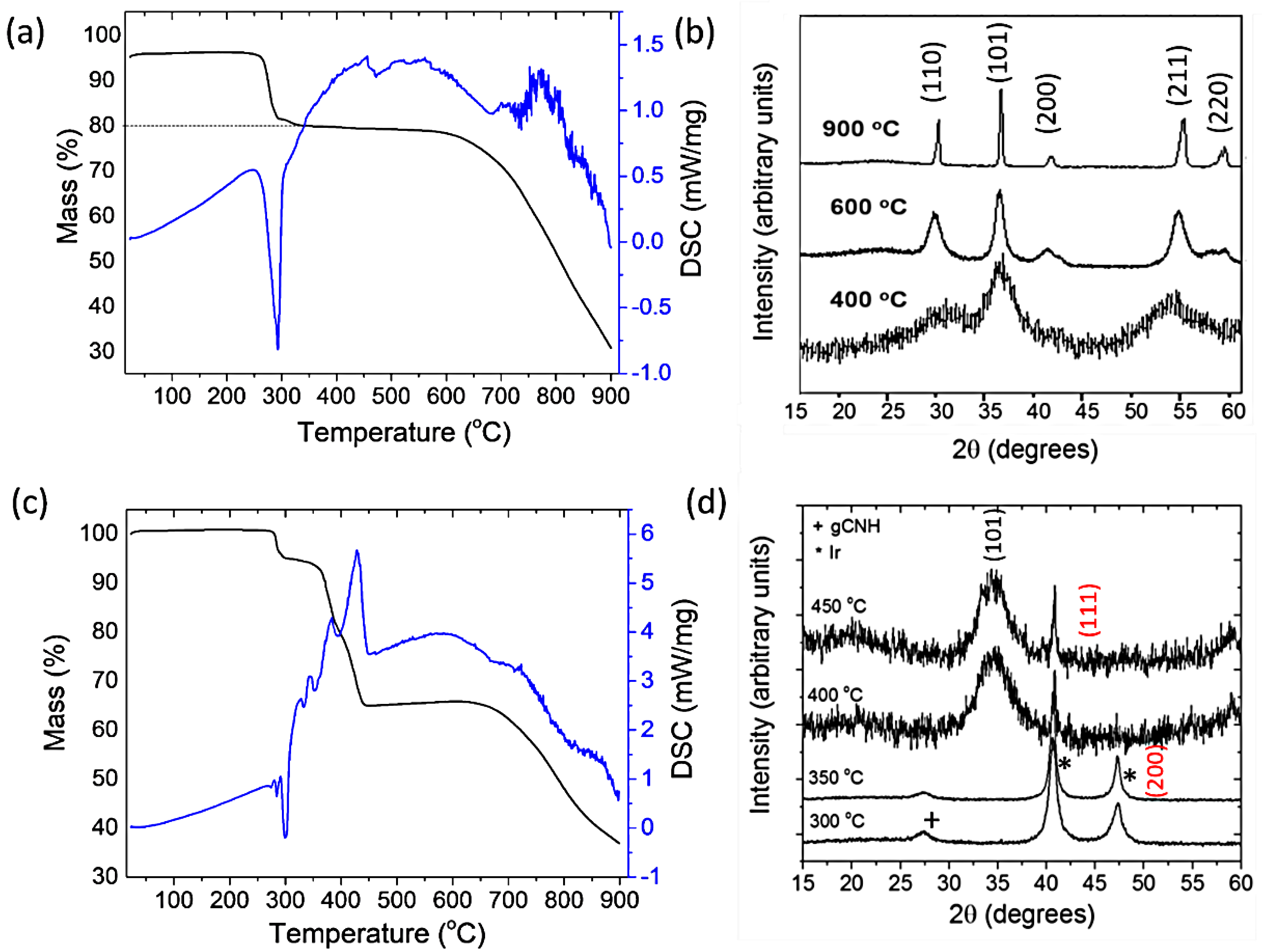
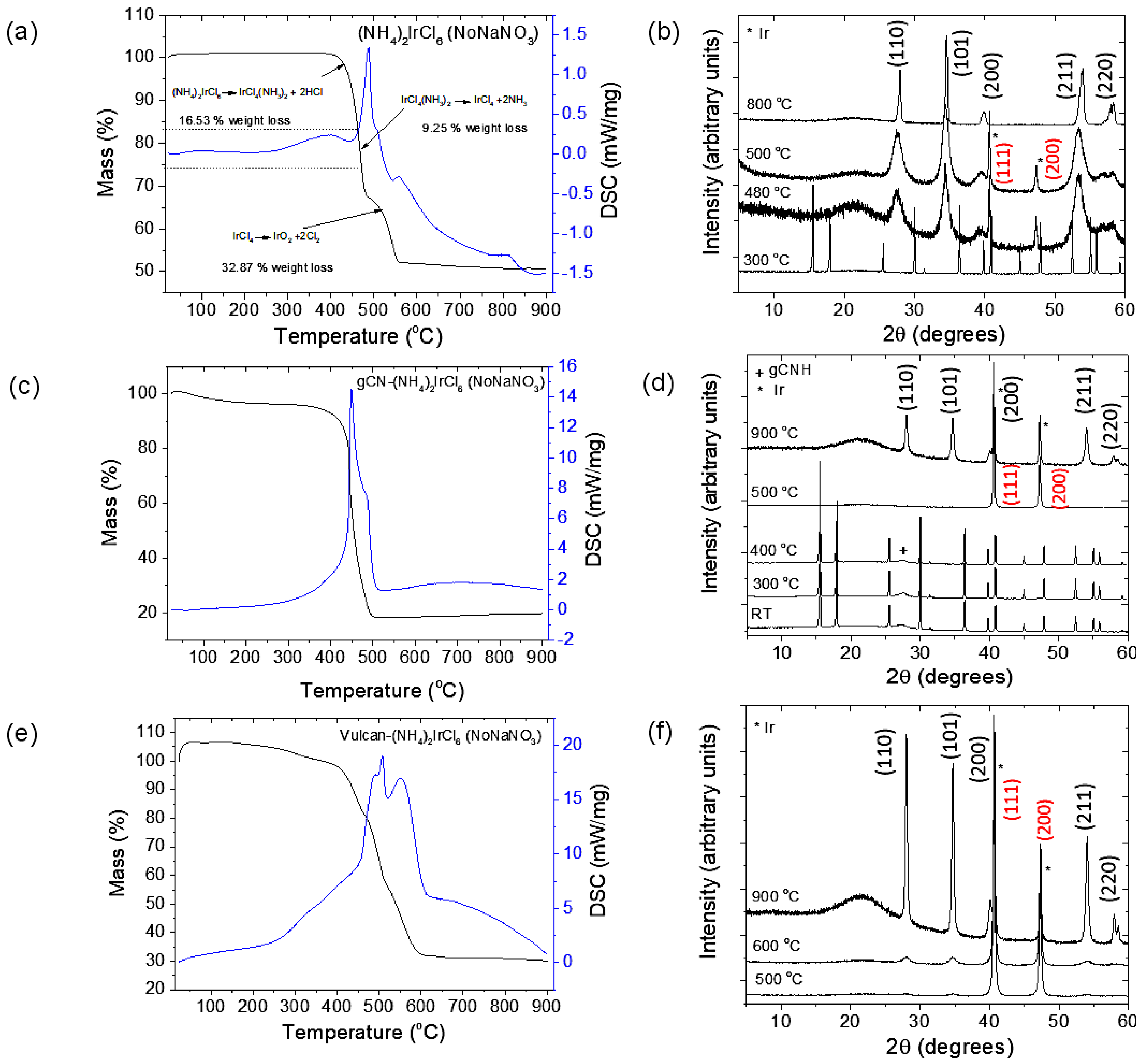
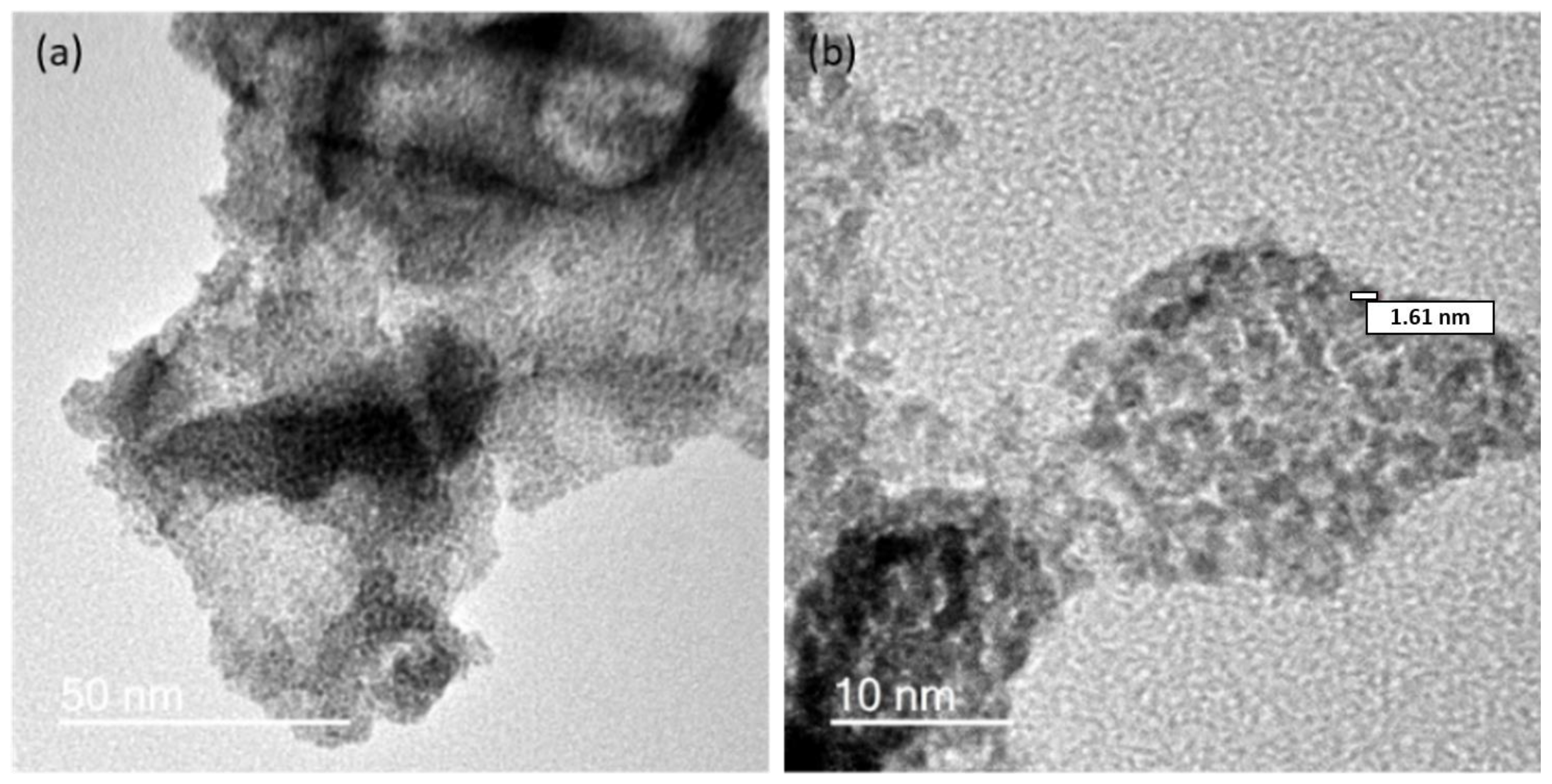
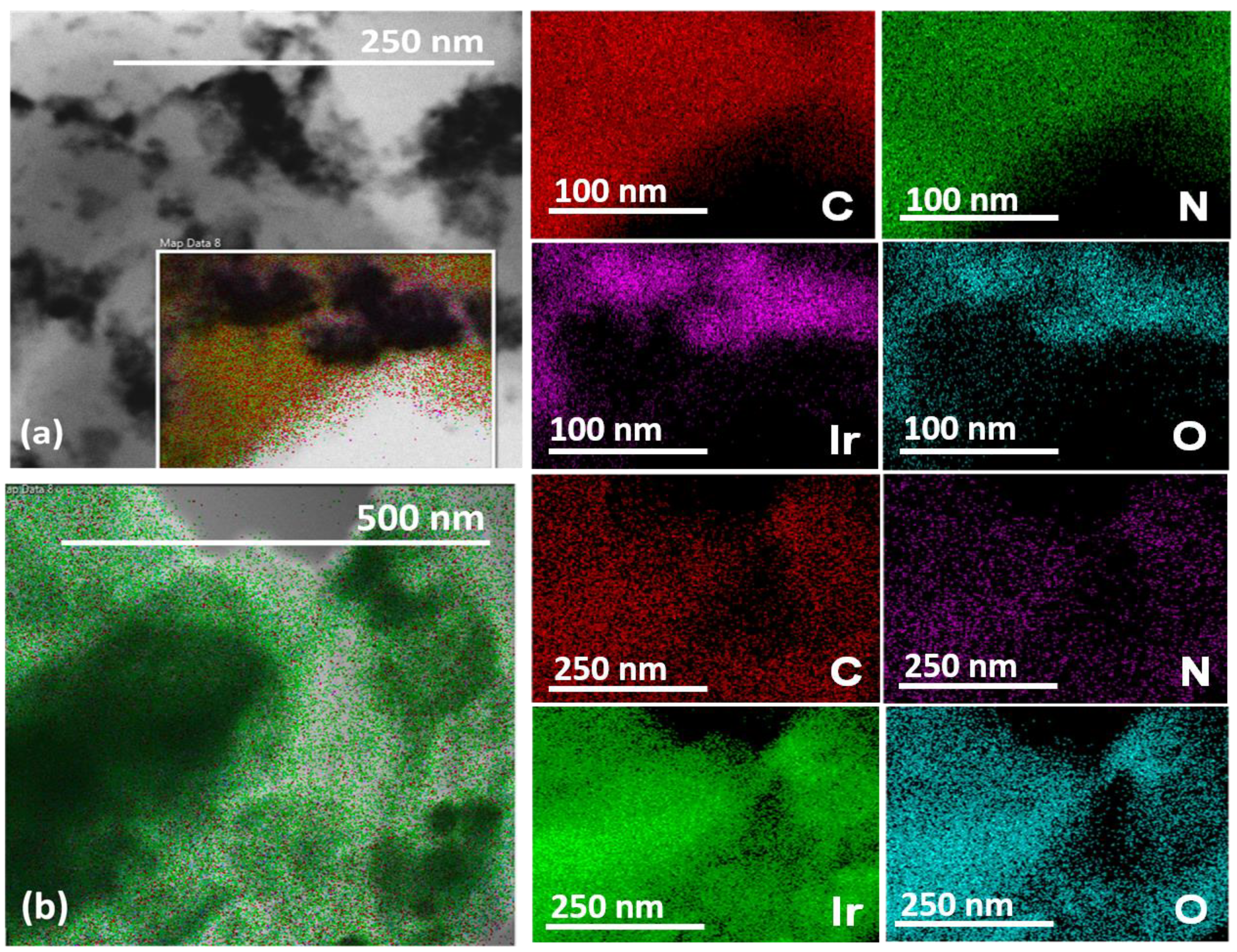
2.1. Preparation of IrO2 and gCNH-IrO2 Electrocatalysts
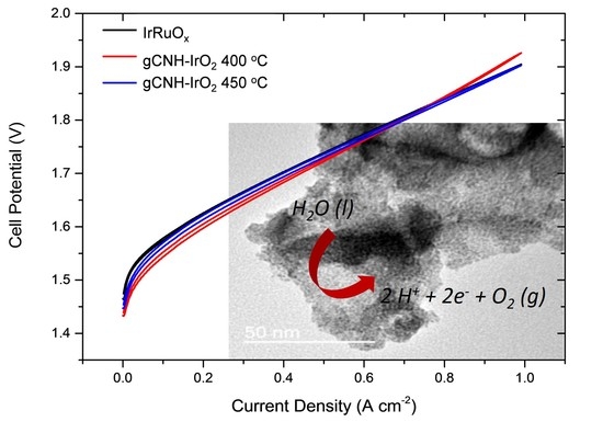
2.2. Electrochemical Performance of gCNH-IrO2 Composites
3. Materials and Methods
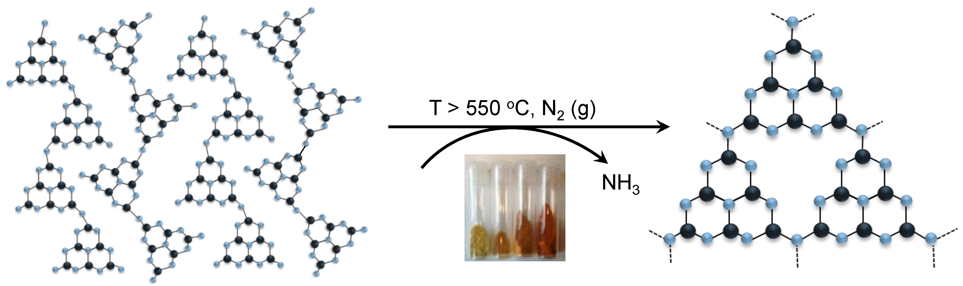
3.1. Synthesis of gCNH
3.2. Synthesis of IrO2 Nanoparticles
3.3. Synthesis of gCNH-IrO2
3.4. Membrane Electrode Assembly (MEA) Preparation
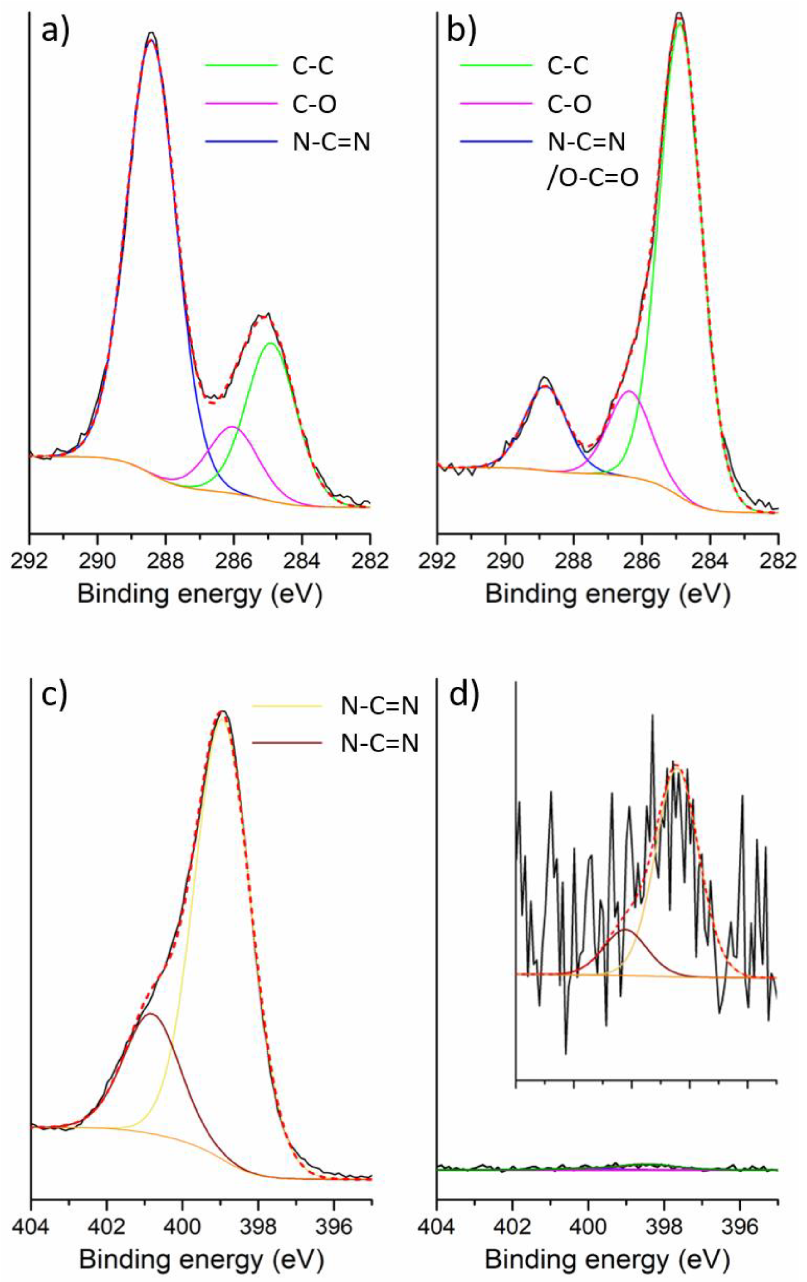
3.5. Structural and Compositional Characterization
3.6. Electrochemical Performance Evaluation
4. Conclusions
Author Contributions
Funding
Conflicts of Interest
References
- Russell, J.H.; Nuttall, L.J.; Fickett, A.P. Hydrogen generation by solid polymer electrolyte water electrolysis. Am. Chem. Soc. Div. Fuel Chem. Prepr. 1973, 18, 24–40. [Google Scholar]
- Haryanto, A.; Fernando, S.; Murali, N.; Adhikari, S. Current status of hydrogen production techniques by steam reforming of ethanol: A review. Energy Fuels 2005, 19, 2098–2106. [Google Scholar] [CrossRef]
- Fabbri, E.; Habereder, A.; Waltar, K.; Kötz, R.; Schmidt, T.J. Developments and perspectives of oxide-based catalysts for the oxygen evolution reaction. Catal. Sci. Technol. 2014, 4, 3800–3821. [Google Scholar] [CrossRef] [Green Version]
- De Pauli, C.P.; Trasatti, S. Electrochemical surface characterization of IrO2+SnO2 mixed oxide electrocatalysts. J. Electroanal. Chem. 1995, 396, 161–168. [Google Scholar] [CrossRef]
- Morimitsu, M.; Otogawa, R.; Matsunaga, M. Effects of cathodizing on the morphology and composition of IrO2-Ta2O5/Ti anodes. Electrochim. Acta 2000, 46, 401–406. [Google Scholar] [CrossRef]
- Terezo, A.J.; Bisquert, J.; Pereira, E.C.; Garcia-Belmonte, G. Separation of transport, charge storage and reaction processes of porous electrocatalytic IrO2 and IrO2/Nb2O5 electrodes. J. Electroanal. Chem. 2001, 508, 59–69. [Google Scholar] [CrossRef]
- Chanda, D.; Hnát, J.; Bystron, T.; Paidar, M.; Bouzek, K. Optimization of synthesis of the nickel-cobalt oxide based anode electrocatalyst and of the related membrane-electrode assembly for alkaline water electrolysis. J. Power Sources 2017, 347, 247–258. [Google Scholar] [CrossRef]
- Marshall, A.T.; Sunde, S.; Tsypkin, M.; Tunold, R. Performance of a PEM water electrolysis cell using IrxRuyTazO2 electrocatalysts for the oxygen evolution electrode. Int. J. Hydrogen Energy 2007, 32, 2320–2324. [Google Scholar] [CrossRef]
- Audichon, T.; Mayousse, E.; Napporn, T.W.; Morais, C.; Comminges, C.; Kokoh, K.B. Elaboration and characterization of ruthenium nano-oxides for the oxygen evolution reaction in a Proton Exchange Membrane Water Electrolyzer supplied by a solar profile. Electrochim. Acta 2014, 132, 284–291. [Google Scholar] [CrossRef]
- Fuentes, R.E.; Rau, S.; Smolinka, T.; Weidner, J.W. Bimetallic electrocatalysts supported on TiO2 for PEM water electrolyzer. ECS Trans. 2010, 28, 23–35. [Google Scholar]
- Reier, T.; Pawolek, Z.; Cherevko, S.; Bruns, M.; Jones, T.; Teschner, D.; Selve, S.; Bergmann, A.; Nong, H.N.; Schlögl, R.; et al. Molecular insight in structure and activity of highly efficient, low-Ir Ir–Ni oxide catalysts for electrochemical water splitting (OER). J. Am. Chem. Soc. 2015, 137, 13031–13040. [Google Scholar] [CrossRef] [PubMed]
- Tunold, R.; Marshall, A.; Rasten, E.; Tsypkin, M.; Owe, L.; Sunde, S. Materials for Electrocatalysis of Oxygen Evolution in PEM Water Electrolysis. Ph.D. Thesis, University of Canterbury, New York, NY, USA, 2010. [Google Scholar]
- Chen, D.; Chen, C.; Baiyee, Z.M.; Shao, Z.; Ciucci, F. Nonstoichiometric oxides as low-cost and highly-efficient oxygen reduction/evolution catalysts for low-temperature electrochemical devices. Chem. Rev. 2015, 115, 9869–9921. [Google Scholar] [CrossRef] [PubMed]
- Zhang, Y.; Ouyang, B.; Xu, J.; Jia, G.; Chen, S.; Rawat, R.S.; Fan, H.J. Rapid Synthesis of Cobalt Nitride Nanowires: Highly Efficient and Low-Cost Catalysts for Oxygen Evolution. Angew. Chem. Int. Ed. 2016, 55, 8670–8674. [Google Scholar] [CrossRef] [PubMed]
- McAteer, D.; Godwin, I.J.; Ling, Z.; Harvey, A.; He, L.; Boland, C.S.; Vega-Mayoral, V.; Szydłowska, B.; Rovetta, A.A.; Backes, C.; et al. Liquid Exfoliated Co(OH)2 Nanosheets as Low-Cost, Yet High-Performance, Catalysts for the Oxygen Evolution Reaction. Adv. Energy Mater. 2018. [Google Scholar] [CrossRef]
- Anantharaj, S.; Ede, S.R.; Sakthikumar, K.; Karthick, K.; Mishra, S.; Kundu, S. Recent trends and perspectives in electrochemical water splitting with an emphasis on sulfide, selenide, and phosphide catalysts of Fe, Co, and Ni: A review. ACS Catal. 2016, 6, 8069–8097. [Google Scholar] [CrossRef]
- Han, L.; Dong, S.; Wang, E. Transition-Metal (Co, Ni, and Fe)-Based Electrocatalysts for the Water Oxidation Reaction. Adv. Mater. 2016, 28, 9266–9291. [Google Scholar] [CrossRef] [PubMed]
- Wang, J.; Cui, W.; Liu, Q.; Xing, Z.; Asiri, A.M.; Sun, X. Recent Progress in Cobalt-Based Heterogeneous Catalysts for Electrochemical Water Splitting. Adv. Mater. 2016, 28, 215–230. [Google Scholar] [CrossRef] [PubMed]
- Galán-Mascarós, J.R. Water oxidation at electrodes modified with earth-abundant transition-metal catalysts. ChemElectroChem 2015, 2, 37–50. [Google Scholar] [CrossRef]
- Su, D.S.; Perathoner, S.; Centi, G. Nanocarbons for the development of advanced catalysts. Chem. Rev. 2013, 113, 5782–5816. [Google Scholar] [CrossRef] [PubMed]
- Xu, J.; Liu, G.; Li, J.; Wang, X. The electrocatalytic properties of an IrO2/SnO2 catalyst using SnO2 as a support and an assisting reagent for the oxygen evolution reaction. Electrochim. Acta 2012, 59, 105–112. [Google Scholar] [CrossRef]
- Mazúr, P.; Polonský, J.; Paidar, M.; Bouzek, K. Non-conductive TiO2 as the anode catalyst support for PEM water electrolysis. Int. J. Hydrogen Energy 2012, 37, 12081–12088. [Google Scholar] [CrossRef]
- Park, S.; Shao, Y.; Liu, J.; Wang, Y. Oxygen electrocatalysts for water electrolyzers and reversible fuel cells: Status and perspective. Energy Environ. Sci. 2012, 5, 9331–9344. [Google Scholar] [CrossRef]
- Xu, J.; Aili, D.; Li, Q.; Christensen, E.; Jensen, J.O.; Zhang, W.; Hansen, M.K.; Liu, G.; Wang, X.; Bjerrum, N.J. Oxygen evolution catalysts on supports with a 3-D ordered array structure and intrinsic proton conductivity for proton exchange membrane steam electrolysis. Energy Environ. Sci. 2014, 7, 820–830. [Google Scholar] [CrossRef]
- Marshall, A.T.; Haverkamp, R.G. Electrocatalytic activity of IrO2–RuO2 supported on Sb-doped SnO2 nanoparticles. Electrochim. Acta 2010, 55, 1978–1984. [Google Scholar] [CrossRef]
- Linse, N.; Gubler, L.; Scherer, G.G.; Wokaun, A. The effect of platinum on carbon corrosion behavior in polymer electrolyte fuel cells. Electrochim. Acta 2011, 56, 7541–7549. [Google Scholar] [CrossRef]
- Antolini, A.; Gonzalez, E.R. Ceramic materials as supports for low-temperature fuel cell catalysts. Solid State Ion. 2009, 180, 746–763. [Google Scholar] [CrossRef]
- Rabis, A.; Rodriguez, P.; Schmidt, T.J. Electrocatalysis for polymer electrolyte fuel cells: Recent achievements and future challenges. ACS Catal. 2012, 2, 864–889. [Google Scholar] [CrossRef]
- Chetty, R.; Kundu, S.; Xia, W.; Bron, M.; Schuhmann, W.; Chirila, V.; Brandl, W.; Reinecke, T.; Muhler, M. PtRu nanoparticles supported on nitrogen-doped multiwalled carbon nanotubes as catalyst for methanol electrooxidation. Electrochim. Acta 2009, 54, 4208–4215. [Google Scholar] [CrossRef]
- Kundu, S.; Nagaiah, T.C.; Xia, W.; Wang, Y.; Dommele, S.V.; Bitter, J.H.; Santa, M.; Grundmeier, G.; Bron, M.; Schuhmann, W.; et al. Electrocatalytic activity and stability of nitrogen-containing carbon nanotubes in the oxygen reduction reaction. J. Phys. Chem. C 2009, 113, 14302–14310. [Google Scholar] [CrossRef]
- Lei, Z.; An, L.; Dang, L.; Zhao, M.; Shi, J.; Bai, S.; Cao, Y. Highly dispersed platinum supported on nitrogen-containing ordered mesoporous carbon for methanol electrochemical oxidation. Microporous Mesoporous Mater. 2009, 119, 30–38. [Google Scholar] [CrossRef]
- Ozaki, J.-I.; Anahara, T.; Kimura, N.; Oya, A. Simultaneous doping of boron and nitrogen into a carbon to enhance its oxygen reduction activity in proton exchange membrane fuel cells. Carbon 2006, 44, 3358–3361. [Google Scholar] [CrossRef]
- Wu, G.; Li, D.; Dai, C.; Wang, D.; Li, N. Well-dispersed high-loading Pt nanoparticles supported by shell-core nanostructured carbon for methanol electrooxidation. Langmuir 2008, 24, 3566–3575. [Google Scholar] [CrossRef] [PubMed]
- Roy, S.C.; Christensen, P.A.; Hamnett, A.; Thomas, K.M.; Trapp, V. Direct methanol fuel cell cathodes with sulfur and nitrogen-based carbon functionality. J. Electrochem. Soc. 1996, 143, 3073–3079. [Google Scholar] [CrossRef]
- Negro, E.; Vezzù, K.; Bertasi, F.; Schiavuta, P.; Toniolo, L.; Polizzi, S.; Di Noto, V. Interplay between nitrogen concentration, structure, morphology, and electrochemical performance of PdCoNi “core-shell” carbon nitride electrocatalysts for the oxygen reduction reaction. ChemElectroChem 2014, 1, 1359–1369. [Google Scholar] [CrossRef]
- Di Noto, V.; Negro, E.; Polizzi, S.; Vezzù, K.; Toniolo, L.; Cavinato, G. Synthesis, studies and fuel cell performance of “core-shell” electrocatalysts for oxygen reduction reaction based on a PtNix carbon nitride “shell” and a pyrolyzed polyketone nanoball “core”. Int. J. Hydrogen Energy 2014, 39, 2812–2827. [Google Scholar] [CrossRef] [Green Version]
- Zhou, Y.; Pasquarelli, R.; Holme, T.; Berry, J.; Ginley, D.; O’Hayre, R. Improving PEM fuel cell catalyst activity and durability using nitrogen-doped carbon supports: Observations from model Pt/HOPG systems. J. Mater. Chem. 2009, 19, 7830–7838. [Google Scholar] [CrossRef]
- Mansor, N.; Jorge, A.B.; Corà, F.; Gibbs, C.; Jervis, R.; McMillan, P.F.; Wang, X.; Brett, D.J.L. Graphitic carbon nitride supported catalysts for polymer electrolyte fuel cells. J. Phys. Chem. C 2014, 118, 6831–6838. [Google Scholar] [CrossRef] [PubMed]
- Mansor, N.; Jorge, A.B.; Corà, F.; Gibbs, C.; Jervis, R.; McMillan, P.F.; Wang, X.; Brett, D.J.L. Development of graphitic-carbon nitride materials as catalyst supports for polymer electrolyte fuel cells. ECS Trans. 2013, 58, 1767–1778. [Google Scholar] [CrossRef]
- Zheng, Y.; Liu, J.; Liang, J.; Jaroniec, M.; Qiao, S.Z. Graphitic carbon nitride materials: Controllable synthesis and applications in fuel cells and photocatalysis. Energy Environ. Sci. 2012, 5, 6717–6731. [Google Scholar] [CrossRef]
- Jorge, A.B.; Dedigama, I.; Mansor, N.; Jervis, R.; Miller, T.S.; Corà, F.; Shearing, P.; Gibbs, C.; McMillan, P.F.; Brett, D.J.L. Graphitic carbon nitride materials for energy applications. ECS Trans. 2015, 64, 13–30. [Google Scholar] [CrossRef]
- Mansor, N.; Jia, J.; Miller, T.; Suter, T.; Jorge, A.B.; Gibbs, C.; Shearing, P.R.; McMillan, P.M.; Mattevi, C.; Shaffer, M.; et al. Graphitic carbon nitride-graphene hybrid nanostructure as a catalyst support for polymer electrolyte membrane fuel cells. ECS Trans. 2016, 75, 885–897. [Google Scholar] [CrossRef]
- Mansor, M.; Miller, T.S.; Dedigama, I.; Jorge, A.B.; Jia, J.; Brázdová, V.; Mattevi, C.; Gibbs, C.; Hodgson, D.; Shearing, P.R.; et al. Graphitic carbon nitride as a catalyst support in fuel cells and electrolyzers. Electrochim. Acta 2016, 222, 44–57. [Google Scholar] [CrossRef]
- Miller, T.S.; Jorge, A.B.; Suter, T.M.; Sella, A.; Cora, F.; McMillan, P.F. Carbon nitrides: Synthesis and characterization of new class of functional materials. Phys. Chem. Chem. Phys. 2017, 19, 15613–15638. [Google Scholar] [CrossRef] [PubMed]
- Wang, X.; Maeda, K.; Thomas, A.; Takanabe, K.; Xin, G.; Carlsson, J.M.; Domen, K.; Antonietti, M. A metal-free polymeric photocatalyst for hydrogen production from water under visible light. Nat. Mater. 2009, 8, 76–80. [Google Scholar] [CrossRef] [PubMed]
- Jorge, A.B.; Martin, D.J.; Dhanoa, M.T.S.; Rahman, A.S.; Makwana, N.; Tang, J.; Sella, A.; Corà, F.; Firth, S.; Darr, J.A.; et al. H2 and O2 evolution from water half-splitting reactions by graphitic carbon nitride materials. J. Phys. Chem. C 2013, 117, 7178–7185. [Google Scholar] [CrossRef]
- Wang, X.; Blechert, S.; Antonietti, M. Polymeric graphitic carbon nitride for heterogeneous photocatalysis. ACS Catal. 2012, 2, 1596–1606. [Google Scholar] [CrossRef]
- Su, F.; Mathew, S.C.; Möhlmann, L.; Antonietti, M.; Wang, X.; Blechert, S. Aerobic oxidative coupling of amines by carbon nitride photocatalysis with visible light. Angew. Chem. Int. Ed. 2011, 50, 657–660. [Google Scholar] [CrossRef] [PubMed]
- Liu, J.; Wang, H.; Antonietti, M. Graphitic carbon nitride “reloaded”: Emerging applications beyond (photo) catalysis. Chem. Soc. Rev. 2016, 45, 2308–2326. [Google Scholar] [CrossRef] [PubMed]
- Ong, W.-J.; Tan, L.L.; Ng, Y.H.; Yong, S.T.; Chai, S.P. Graphitic carbon nitride (g-C3N4)-based photocatalysts for artificial photosynthesis and environmental remediation: Are we a step closer to achieving sustainability? Chem. Rev. 2016, 116, 7159–7329. [Google Scholar] [CrossRef] [PubMed]
- Adams, R.; Shriner, R.L. Platinum oxide as a catalyst in the reduction of organic compounds. III. Preparation and properties of the oxide of platinum obtained by the fusion of chloroplatinic acid with sodium nitrate. J. Am. Chem. Soc. 1923, 45, 2171–2179. [Google Scholar] [CrossRef]
- Keenan, C.W.; Giesemann, B.W.; Smith, H.A. Platinum oxide catalysts. J. Am. Chem. Soc. 1954, 76, 229–232. [Google Scholar] [CrossRef]
- Bruce, W.F. The preparation of platinum oxide for catalytic hydrogenations. J. Am. Chem. Soc. 1936, 58, 687–688. [Google Scholar] [CrossRef]
- Voorhees, V.; Adams, R. The use of the oxides of platinum for the catalytic reduction of organic compounds. I. J. Am. Chem. Soc. 1922, 44, 1397–1405. [Google Scholar] [CrossRef]
- Felix, C.; Maiyalagan, T.; Pasupathi, S.; Bladergroen, B.; Linkov, V. Synthesis and optimisation of IrO2 electrocatalysts by Adams’ fusion method for solid polymer electrolyte electrolysers. Micro Nanosyst. 2012, 4, 186–191. [Google Scholar] [CrossRef]


| IrRuOx | gCNH-IrO2-400 °C | gCNH-IrO2-450 °C | ||||
|---|---|---|---|---|---|---|
| 0.1 A cm−2 | 0.7 A cm−2 | 0.1 A cm−2 | 1 A cm−2 | 0.1 A cm−2 | 1 A cm−2 | |
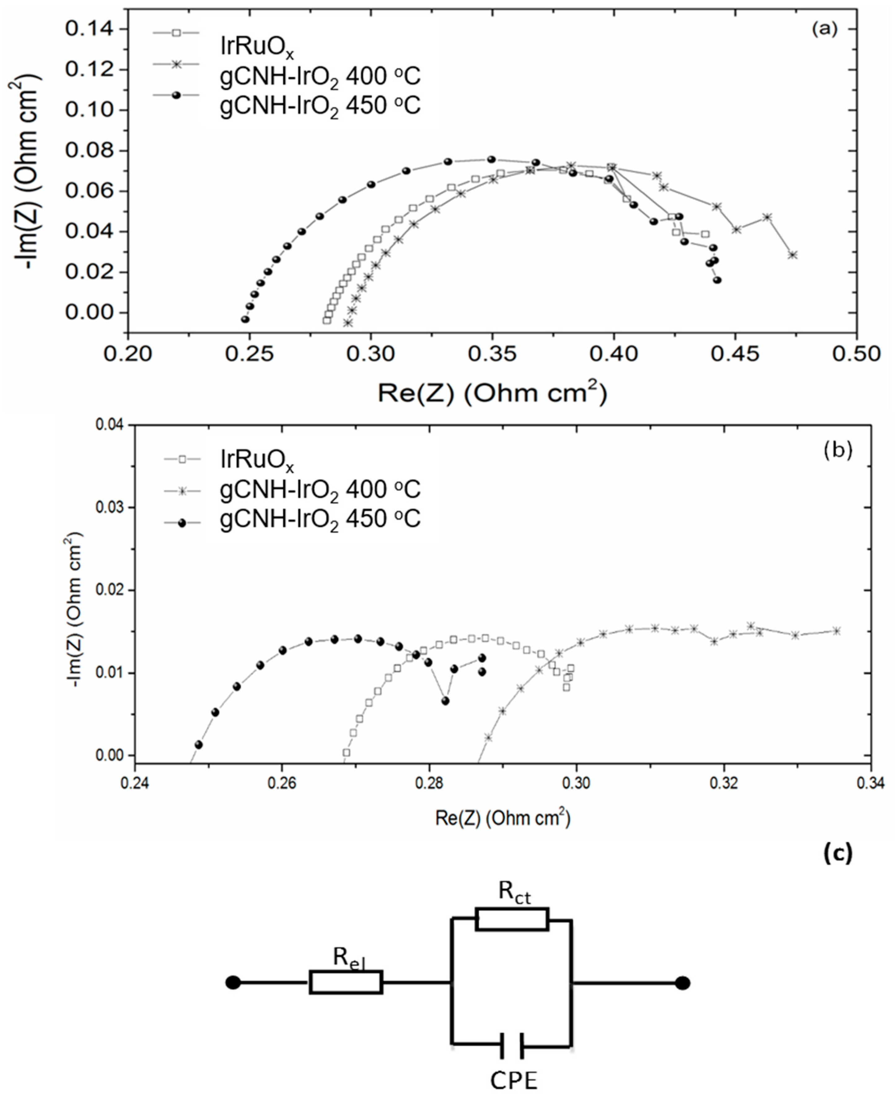
| Rel (Ω cm2) | 0.277 | 0.263 | 0.285 | 0.273 | 0.243 | 0.235 |
| Rct (Ω cm2) | 0.216 | 0.048 | 0.200 | 0.070 | 0.210 | 0.058 |
| CPE (Ω−1sn) | 0.238 | 0.518 | 0.038 | 0.209 | 0.033 | 0.054 |
| n | 0.72 | 0.65 | 0.79 | 0.55 | 0.79 | 0.66 |
© 2018 by the authors. Licensee MDPI, Basel, Switzerland. This article is an open access article distributed under the terms and conditions of the Creative Commons Attribution (CC BY) license (http://creativecommons.org/licenses/by/4.0/).
Share and Cite
Jorge, A.B.; Dedigama, I.; Miller, T.S.; Shearing, P.; Brett, D.J.L.; McMillan, P.F. Carbon Nitride Materials as Efficient Catalyst Supports for Proton Exchange Membrane Water Electrolyzers. Nanomaterials 2018, 8, 432. https://doi.org/10.3390/nano8060432
Jorge AB, Dedigama I, Miller TS, Shearing P, Brett DJL, McMillan PF. Carbon Nitride Materials as Efficient Catalyst Supports for Proton Exchange Membrane Water Electrolyzers. Nanomaterials. 2018; 8(6):432. https://doi.org/10.3390/nano8060432
Chicago/Turabian StyleJorge, Ana Belen, Ishanka Dedigama, Thomas S. Miller, Paul Shearing, Daniel J. L. Brett, and Paul F. McMillan. 2018. "Carbon Nitride Materials as Efficient Catalyst Supports for Proton Exchange Membrane Water Electrolyzers" Nanomaterials 8, no. 6: 432. https://doi.org/10.3390/nano8060432
APA StyleJorge, A. B., Dedigama, I., Miller, T. S., Shearing, P., Brett, D. J. L., & McMillan, P. F. (2018). Carbon Nitride Materials as Efficient Catalyst Supports for Proton Exchange Membrane Water Electrolyzers. Nanomaterials, 8(6), 432. https://doi.org/10.3390/nano8060432