Increasing the Efficiency of Dye-Sensitized Solar Cells by Adding Nickel Oxide Nanoparticles to Titanium Dioxide Working Electrodes

Department of Opto-Electronic Engineering, National Dong Hwa University, Hualien 97401, Taiwan
*
Author to whom correspondence should be addressed.
Coatings 2020, 10(2), 195; https://doi.org/10.3390/coatings10020195
Submission received: 31 January 2020
/
Revised: 20 February 2020
/
Accepted: 21 February 2020
/
Published: 24 February 2020
(This article belongs to the Special Issue Mesoporous Metal Oxide Films)
Abstract
:In this study, nickel oxide (NiO) nanoparticles were added to a titanium dioxide (TiO2) nanoparticle paste to fabricate a dye-sensitized solar cell (DSSC) working electrode by using a screen-printing method. The effects of the NiO proportion in the TiO2 paste on the TiO2 working electrode, DSSC devices, and electron transport characteristics were comprehensively investigated. The results showed that adding NiO nanoparticles to the TiO2 working electrode both inhibited electron transport (a negative effect) and prevented electron recombination with the electrolyte (a positive effect). The electron transit time was extended following an increase in the amount of NiO nanoparticles added, confirming that NiO inhibited electron transport. Furthermore, the energy level difference between TiO2 and NiO generated a potential barrier that prevented the recombination of the electrons in the TiO2 conduction band with the I3- ions in the electrolyte. When the TiO2–NiO ratio was 99:1, the positive effects outweighed the negative effects. Therefore, this ratio was the optimal TiO2–NiO ratio in the electrode for electron transport. The DSSCs with a TiO2–NiO (99:1) working electrode exhibited an optimal power conversion efficiency of 8.39%, which was higher than the DSSCs with a TiO2 working electrode.
1. Introduction
The advancement of science and technology has increased the demand for energy over the years, resulting in a continuous reduction in oil reserves. Carbon dioxide produced by burning fossil fuels has caused global warming and has induced various anomalies in the global climate. Therefore, the development of green energy has attracted scientists’ attention. Grätzel and colleagues introduced dye-sensitized solar cells (DSSCs) in 1991 [1]. Research related to solar cells immediately caught the public’s attention because DSSCs have many advantages such as high efficiency, low cost, and simple fabrication [2,3,4,5,6]. Typical components of a DSSC include a titanium dioxide (TiO2) working electrode, a dye, a platinum (Pt) counter electrode (CE), and an electrolyte [7,8,9,10]. The TiO2 working electrode, which is used for transporting photoelectrons and exhibits a large surface area for dye adsorption and holes for injecting electrolytes, is a key component of a DSSC [11,12,13]. Although other types of wide bandgap oxides can achieve the same effects (e.g., ZnO [14], SnO2 [15], Fe2O3 [16], and Nb2O5 [17]), TiO2 is presently the optimal material for fabricating working electrodes. Previously, DSSCs contained planar TiO2 working electrodes, which exhibit an efficiency of less than 1% because they rely on dye molecules adsorbed on the electrode surface for effective photocurrent generation [18]. Grätzel proposed porous electrodes comprising TiO2 nanoparticles; each micrometer of thickness increases the surface area 100-fold, and the photocurrent generation efficiency can exceed 7% when dye molecules are adsorbed on the electrode surface. Accordingly, the fabrication of TiO2, working electrodes is crucial in manufacturing high-efficiency DSSCs. Arakawa et al. designed six types of electrodes using three types of TiO2 particles (23, 50, and 100 nm) and different mix proportions of TiO2 particles, thereby revealing that a multilayered electrode achieved the optimal performance in photoelectron transport [19]. Kim et al. fabricated TiO2 nanorods and mixed 10% of the nanorods with 90% of the TiO2 nanoparticles; the authors reported that the photocurrent of DSSCs improved considerably when nanorods were added [20]. Recently, novel TiO2 structures, such as nanowires and nanotubes, have been implemented to enhance the performance of TiO2 working electrodes [21,22,23,24]. Various studies have been conducted to improve the design of TiO2 working electrodes [25,26,27].
When light is irradiated on a DSSC, the dye converts from the ground state to the excited state and injects electrons into the conduction band of the TiO2 working electrode, which then transports the electrons to the Pt counter electrode through the fluorine-doped tin oxide (FTO) conductive glass and external circuit. However, the transport does not thoroughly abide by scientific theory; reactions may occur during this procedure to affect the photocurrent and device efficiency. Studies have reported that the following cause a decreased photocurrent: (1) the reverse current caused by the reverse reaction between the dye and the electrolyte, (2) the recombination of electrons in the TiO2 conduction band with the dye molecules, (3) the recombination of electrons in the TiO2 conduction band with the electrolyte, and (4) the spontaneous recombination caused by a decline in the energy of the excited dye molecules [28]. Studies have indicated that barriers can be used to prevent the reverse current and recombination of electrons in the TiO2 conduction band with the dye and electrolyte. Moreover, metal oxides can be applied as electron barriers to improve the transport efficiency of photoelectrons [29,30,31].
Nickel oxide (NiO), a transition metal oxide with a cubic lattice structure, can be synthesized through the solvothermal synthesis, precipitation calcination, chemical precipitation, microwave-assisted hydrothermal method, thermal decomposition, or sol–gel process. NiO is a p-type semiconductor material that is capable of electrocatalysis, high chemical stability, superconductivity, and electron transport. NiO has been widely researched and applied in catalysts, battery cathodes, gas detectors, electrochromic elements, magnetic materials, and photocathodes or counter electrodes in DSSCs [32,33,34,35,36]. Furthermore, the energy-level difference between p-type NiO and n-type TiO2 may generate a potential barrier, which can prevent the recombination of the electrons in the TiO2 conduction band with the I3- ions in the electrolyte, thus enhancing the efficiency of the DSSCs [37]. In this study, NiO nanoparticles were added to the TiO2 nanoparticle solution to create a DSSC working electrode through screen printing, and the effects of the proportion of NiO in the TiO2 solution on the TiO2 working electrode, DSSC devices, and electron transport were investigated.
2. Experiments
2.1. Preparing the Materials
To prepare the ethyl cellulose (EC) solution, 5 g of EC (5–15 mPa∙s, Sigma-Aldrich, St. Louis, MO, USA), 5 g of EC (30–60 mPa∙s, Sigma-Aldrich), and 100 g of absolute alcohol (99.5%) were placed in a serum bottle, evenly mixed with a stir bar at 200 rpm, maintained at 40 °C for 3 days, and cooled to room temperature. To prepare the TiO2 paste, 1.15 g of TiO2 nanoparticles (particle size: 15–20 nm, Aeroxide TiO2 P90), 3.4 g of terpineol (Merck, Darmstadt, Germany), and 4.5 g of the EC solution were placed in a container, combined with an appropriate amount of absolute alcohol, evenly mixed with a stir bar at 200 rpm, maintained at 40 °C for 3 days, and cooled to room temperature. To prepare the TiO2–NiO combined paste, TiO2 and NiO nanoparticles (particle size: 10–20 nm, US Research Nanomaterials, Inc., Houston, TX, USA) were added in proportions of 99:1 (1.1385 g, 0.0115 g), 98:2 (1.127 g, 0.023 g), and 97:3 (1.1155 g, 0.0345 g), respectively, to containers with 3.4 g of terpineol and 4.5 g of the EC solution. Subsequently, an appropriate amount of absolute alcohol was added to the solutions, which were then evenly mixed using stir bars at 200 rpm, maintained at 40 °C for 3 days, and later cooled to room temperature, thus yielding three TiO2–NiO combined pastes in the following proportions: 99:1, 98:2, and 97:3. To prepare a 0.5-mM N719 dye solution, 11.87 mg of N719 dye, 3.92 mg of chenodeoxycholic acid (CDCA), 10 mL of acetonitrile (ACN), and 10 mL of tert-butanol were placed in a sample bottle and subjected to ultrasonic oscillation for 5 min.
2.2. Preparing the DCCS Devices
The FTO conductive glass substrate was cleaned and ultrasonically oscillated in acetone, deionized water, and alcohol (anhydrous ethanol, 99.5%, Echo Chemical Co., Ltd., Taiwan) for 5 min each and dried using nitrogen gas. The working electrode was then prepared by using the screen-printing method. The dried substrate was placed on the screen printer and the TiO2 or TiO2–NiO paste was printed evenly on the screen. A scraper was used to print from top to bottom so that the nanoparticle paste could pass through the screen and could reach the substrate. The printed substrate was placed in a culture dish, covered with another culture dish, sprayed with alcohol (anhydrous ethanol, 99.5%, Echo Chemical Co., Ltd., Taiwan), and rested for 10 min. The substrate was then heated at 100 °C for 10 min and cooled down to room temperature, thus completing the first screen-printing process. A second screen-printing process was then conducted through the repetition of the aforementioned steps on the same substrate. After the substrate was printed with the TiO2 paste twice and cooled to room temperature, the substrate was placed on the screen printer and printed with a TiO2 paste with a 200-nm particle diameter twice to fabricate a scattering layer. The working electrode was placed into a high-temperature furnace and thermal annealed at 500 °C for 30 min, cooled to room temperature, and immersed in the N719 dye solution for 24 h to adsorb the dye. The surface of the working electrode was then cleansed of excess dye with alcohol, thus completing the production of the working electrode (active area: 0.16 cm2).
To prepare the counter electrode, two holes for electrolyte injection with 0.9-mm diameters were created in the FTO conductive glass substrate with a drill. The upper and lower surfaces of the substrate, excluding the 1.65-cm2 area at the center, were then covered with 3M tape. An appropriate amount of the Pt nanoparticle paste was printed evenly onto the substrate with a scraper. After the 3M tape was removed, the substrate was thermal annealed at 450 °C for 30 min and cooled to room temperature, thus completing the production of the counter electrode. Finally, the DSSC devices were packaged. A 60-μm sealing film was cut into a 2 cm × 2 cm square, and a circular hole with a 0.9-cm diameter was cut in the center. The sealing film was placed between the working electrode and the counter electrode, and the two electrodes were adhered by pressing them at 3 kg/cm2 and at 130 °C in a hot-press for 90 s and cooled to room temperature. Subsequently, 7 μL of electrolyte solution (0.6 M 1-buty-3-methylimidazolium iodide, 0.05 M LiI, 0.03 M I2, 0.5 M 4-tert-butylpyridine, 0.1 M guanidine thiocyanate, and 5:1 of an ACN–valeronitrile solution) was injected into the electrolyte injection holes. Finally, the sealing film and glasses were used to cover the injection holes, followed by pressing at 130 °C and at 3 kg/cm2 for 15 s to prevent electrolyte leakage, thus completing the fabrication of the DSSC devices.
2.3. Characteristics of the Working Electrode and the DSSC Devices
In this study, the characteristics of the working electrode, DSSC devices, and electron transport were analyzed. A scanning electron microscope (SEM) was employed to examine the surface of the working electrode. An energy dispersive spectrometer (EDS) was incorporated to observe the elemental compositions and proportions of the electrode. An X-ray diffractometer (XRD) was applied to analyze the lattice structure of the electrode. An X-ray photoelectron spectrometer (XPS) was used to determine the elemental compositions and chemical bonds on the surface of the electrode. The characteristics of the DSSC devices were investigated using current density–voltage (J–V), incident photon-to-electron conversion efficiency (IPCE), and electrochemical impedance spectroscopy (EIS). A simulated AM 1.5 G solar light emitted by a 550-W Xenon lamp solar simulator was used to measure the current density–voltage (J–V) characteristics of the DSSCs. The intensity of the incident light was calibrated to 100 mW/cm2 by employing a reference cell. The reference cell had been given certification Bunkoh-Keiki Co Ltd, Tokyo, Japan. An external bias voltage was applied to the cell, and the photocurrent resulting was measured to obtain the photocurrent–voltage curves. The open-circuit voltage (VOC), short-circuit current density (JSC), fill factor (FF), and power conversion efficiency (PCE) for the DSSCs were extracted from the J–V characteristics. The electron transport within the DSSC was examined using intensity-modulated photocurrent spectroscopy (IMPS) and intensity-modulated photovoltage spectroscopy (IMVS).
3. Results and Discussion
3.1. Characteristics of the Working Electrode
Figure 1a shows the surface morphology of the TiO2 working electrode as observed through the SEM. The TiO2 nanoparticles formed an even, thin film on the FTO conductive glass. The mesoporous structure of the thin film exhibited a high surface area and enhanced the N719 dye adsorption and photocurrent generation, thereby reinforcing the photoelectron conversion efficiency. The diameters of the TiO2 nanoparticles were 15–20 nm. Figure 1b–d shows the surfaces of the TiO2–NiO (99:1), TiO2–NiO (98:2), and TiO2–NiO (97:3) working electrodes, respectively. All the working electrodes exhibited the same mesoporous TiO2 structure regardless of whether or not they were mixed with NiO. However, some parts of the electrodes differed from others in their compositions and were relatively aggregated; this may have been caused by the NiO mixture and the surface characteristics of TiO2 and NiO nanoparticles. Overall, NiO nanoparticles were evenly distributed on the TiO2–NiO working electrodes. Previous studies have indicated that the thickness of a working electrode affects its photoelectron conversion efficiency, and an approximate thickness of 13 μm yields the optimal conversion efficiency. Therefore, this study investigated the effects of the NiO nanoparticles on the photoelectron conversion efficiency of the electrodes at the optimal thickness. Figure 2 shows the cross-sectional image of the working electrode as observed through the SEM. The lower layer was the TiO2 active layer with a 7.125-μm thickness, and the upper layer was the large-particle TiO2 scattering layer with a 6.563-μm thickness. The total thickness was 13.688 μm, satisfying the expectations of a working electrode. This study also investigated the adsorbed dye amounts on the working electrodes. The adsorbed N719 dye amounts on the TiO2, TiO2–NiO (99:1), TiO2–NiO (98:2), and TiO2–NiO (97:3) working electrodes were 126.2, 124.8, 123.6, and 122.3 nmol/cm2, respectively. The adsorbed dye amounts decreased slightly following an increase in the proportion of NiO.
Figure 3 shows the EDS analysis of the elemental compositions and proportions of the working electrode. As shown in Figure 3a, Ni did not exist on the electrode. Figure 3b–d shows the EDS analysis results of the TiO2–NiO (99:1), TiO2–NiO (98:2), and TiO2–NiO (97:3) working electrodes, respectively. A rise in the proportion of NiO increased the amount of Ni on the electrode in both its weight (from 0.05% to 0.90%) and atomic ratios (from 0.02% to 0.40%), confirming the presence of NiO in the electrodes. The EDS results showed that the Ti to Ni ratio is different from the predicted proportions (i.e., 99:1, 98:2, and 97:3). This is because EDS cannot be considered a quantitative method of analysis; it can only be used as a qualitative analysis for various elements in an electrode. Figure 4 shows the XRD analysis results of the lattice structures of the TiO2, TiO2–NiO (99:1), TiO2–NiO (98:2), and TiO2–NiO (97:3) working electrodes. The characteristic peaks of the FTO were at 26.5°, 33.7°, 37.8°, 51.6°, 61.7°, and 65.6°. The characteristic peaks of the anatase TiO2 were at 25.3° and 48.2°, and their respective corresponding lattice planes were (101) and (200). The characteristic peak of the rutile TiO2 was at 54.7°, and its corresponding lattice plane was (211). The characteristic peak of NiO was at 43.3°, and its corresponding lattice plane was (200) [38,39,40,41]; an increase in the proportion of NiO raised the value of the characteristic peak. According to the XRD analysis, the diffraction peak of NiO was at 43.3°, and the NiO lattice structures were observed in the TiO2–NiO (99:1), TiO2–NiO (98:2), and TiO2–NiO (97:3) working electrodes.
Regarding the XPS analysis results of the elemental compositions and chemical bonds on the surfaces of the working electrodes, Figure 5a shows the O1s XPS analysis results of TiO2 in the TiO2–NiO (99:1), TiO2–NiO (98:2), and TiO2–NiO (97:3) electrodes. Figure 5b shows the Ti2p XPS analysis results. According to Figure 5a, no significant difference was observed among the electrodes regarding their O1s binding energy characteristic peak. However, the peak intensities of the electrodes with NiO were lower than those of the TiO2 electrodes without NiO. The binding energy characteristic peak was at 529.8 eV, indicating the formation of an O2− bond [42]. According to the Ti2p XPS analysis (Figure 5b), no significant difference was observed among the electrodes regarding their Ti2p binding-energy characteristic peaks; however, the peak intensity decreased following an increase in the proportion of NiO. This was because adding NiO led to a decrease in the proportion of TiO2 and, subsequently, the Ti bond. The Ti bond energy could be divided into Ti 2p1/2 and Ti 2p3/2, which exhibited the characteristic peaks at 464.2 and 458.5 eV and which were both Ti4+ bonds [43]. Accordingly, the strength of the Ti binding-energy peak signals decreased following an increase in the proportion of NiO. Figure 6 displays the full spectrum XPS results of the TiO2, TiO2–NiO (99:1), TiO2–NiO (98:2), and TiO2–NiO (97:3) working electrodes. The signals at 285, 458.5, 529.8, and 566.4 eV correspond to the C1s, Ti2p, O1s, and Ti2s peaks, respectively. Because the amount of NiO added in the TiO2–NiO electrode was nonsignificant, no Ni bonds were detected on the surfaces of the electrodes.
3.2. Characteristics of the DSSC Devices
In this study, the J−V curves, IPCE, and EIS of the DSSC devices were further analyzed. Figure 7 shows the J−V curves of the DSSCs. The DSSC’s photoelectric characteristics, including the short-circuit current density (JSC), open circuit voltage (VOC), fill factor (FF), and power conversion efficiency (PCE) are listed in Table 1. The reproducibility of the device performances based on various working electrodes was investigated. For each condition, four DSSC devices were fabricated and analyzed. The values shown in Table 1 are averaged values and standard deviations of four devices made under identical conditions.
According to the experimental results, the JSC of the TiO2 working electrode was 16.49 mA/cm2 without NiO, which was increased to 17.15 mA/cm2 when NiO was added to TiO2–NiO (99:1) and dropped to 15.69 mA/cm2 and 15.34 mA/cm2 at the respective ratios of 98:2 and 97:3. However, the VOC was consistently 0.73 V throughout. The FFs of the working electrode were 0.64, 0.67, 0.67, and 0.66 when the TiO2–NiO ratios were 100:0, 99:1, 98:2, and 97:3, respectively; an increase in the proportion of NiO led to a rise in the FF until the TiO2–NiO ratio was 97:3, at which point the FF started to decrease. The PCEs were 7.70%, 8.39%, 7.67%, and 7.39% at the TiO2–NiO ratios of 100:0, 99:1, 98:2, and 97:3, respectively. According to the J−V curve analysis, adding an appropriate amount of NiO increased the PCE of the DSSC by 8.96%. In a DSSC, the electrons in the conduction band of TiO2 might recombine with the dye and electrolyte. The p-type semiconductor material of NiO exhibits an energy level (−2.36 eV vs. the normal hydrogen electrode) higher than that of TiO2 (−0.25 eV vs. the normal hydrogen electrode) [44]. The energy-level difference between NiO and TiO2 formed a potential barrier that prevented the recombination of the electrons in the TiO2 conduction band with the I3- ions in the electrolyte. This also enabled the electrons to move to the external circuit, thus improving the PCE and JSC. However, when an excessive amount of NiO was added, potential barriers prevented the electrons from moving to the external circuit, thus inhibiting the PCE and JSC.
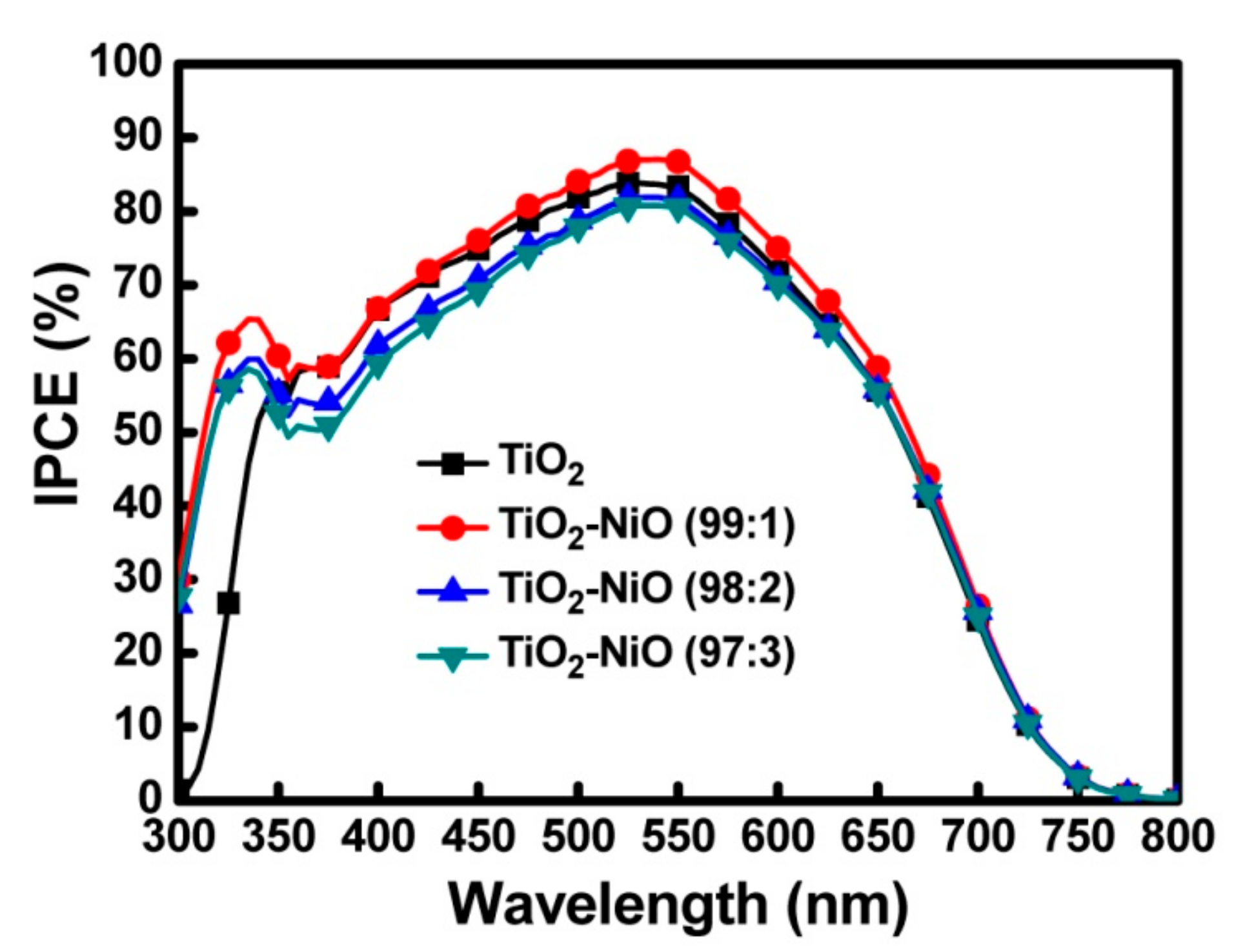
According to the IPCE analysis, the range of wavelengths was 300–800 nm (Figure 8). The IPCE peak value (88.3%) of the TiO2–NiO (99:1) working electrode was identified at 540 nm, the highest IPCE value, followed by the peak values of pure TiO2, TiO2–NiO (98:2), and TiO2–NiO (97:3). The IPCE value was positively correlated to JSC. Therefore, the overall IPCE analysis result was consistent with the changes in the JSC in the J−V curve analysis. The IPCE value was highest at the wavelength range of 400–650 nm, which was the range for N719 dye absorption. At 340 nm, each of the devices mixed with NiO exhibited an absorption peak and those without NiO did not. This was because the 3.6 eV [45] bandgap of NiO corresponded to the absorption wavelength of 344 nm in the photon energy equation, which was consistent with the IPCE analysis results.
The EIS analysis results of the DSSCs are shown in Figure 9. The range of measurement frequencies was 0.1 Hz to 100 kHz, and the AC amplitude was 0.01 V. EIS assesses the charge transfer processes in DSSCs, such as electron transport at the Pt/electrolyte interface (RCE), electron transport and charge recombination at the TiO2/dye/electrolyte interface (Rct), I3- transport in the electrolyte (WD), and series resistance associated with the contribution from the FTO and counter electrodes (Rs). To extract the quantitative impedance characteristics of the devices, an equivalent circuit model (in Figure 9) was used to analyze the internal impedance of the devices. The extracted quantitative impedance parameters are listed in Table 2. The EIS results showed that the charge transfer resistance at the TiO2/dye/electrolyte interface (Rct) was minimal when no NiO was added and increased marginally following an increase in the proportion of NiO. Accordingly, NiO inhibited the electron transport more effectively than TiO2, and adding NiO in the TiO2 working electrode slightly increased the resistance of the electron transport. Furthermore, the energy-level difference between NiO and TiO2 formed a potential barrier that prevented the recombination of the electrons in the TiO2 conduction band with the I3- ions in the electrolyte, thereby increasing the charge transfer impedance at the TiO2/dye/electrolyte interface.
3.3. Characteristics of the Electron Transport
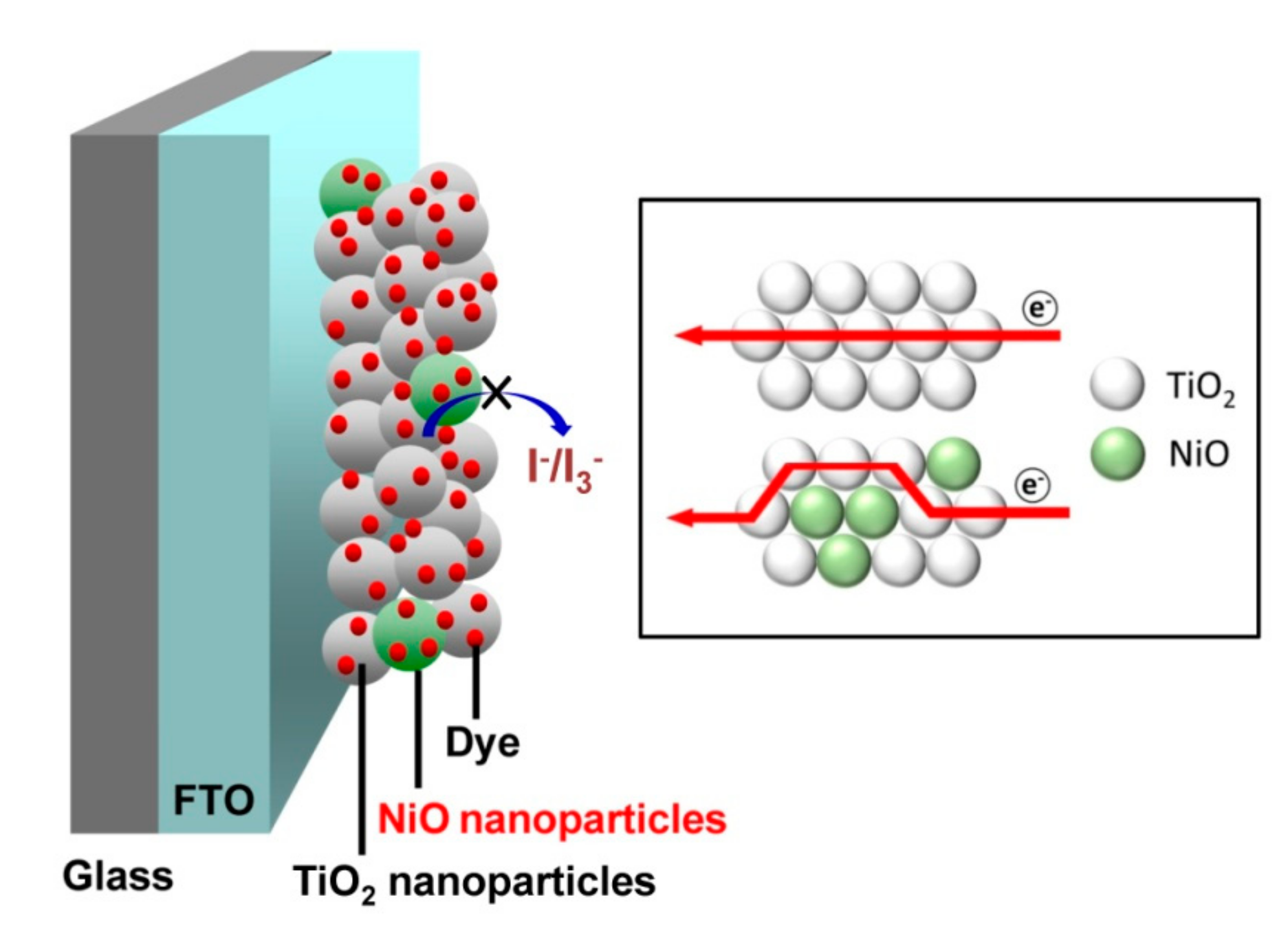
Figure 10 and Table 3 show the results of the IMPS and IMVS analyses, which were conducted to further clarify the characteristics of the electron transport in the DSSC. The measured data were presented on a complex plane, and the frequency corresponding to the imaginary minimal value was applied to calculate the electron transit time (τd) and the electron lifetime (τn) by the formulas τd = 1/2πfmin (IMPS) and τn = 1/2πfmin (IMVS). After obtaining the electron transit time (τd) and lifetime (τn), the diffusion coefficient (D) can be calculated by the formula D = L2/τd, where L is the film thickness of the working electrode. The charge collection efficiency (ηCC) can be calculated by the formula ηCC = 1−τd/τn [46]. According to the IMPS analysis, the electron transit times of the working electrode were 14.67, 15.84, 23.25, and 54.09 ms at the TiO2–NiO ratios of 100:0, 99:1, 98:2, and 97:3, respectively. This revealed that adding NiO to the electrode caused a decrease in the amount of TiO2 (which facilitated electron transport) and an increase in the transport distance, thus extending the electron transit time. The mechanism of electron transport in TiO2 and TiO2–NiO working electrodes is shown in Figure 11. According to the IMVS analysis, the electron lifetimes of the working electrode were 116.53, 135.86, 100.42, and 92.56 ms at the TiO2–NiO ratios of 100:0, 99:1, 98:2, and 97:3, respectively. At the 99:1 ratio, a small amount of NiO generated a potential barrier through its energy-level difference with TiO2 and thereby reduced the electron recombination, thus maximizing the electron lifetime in the process. An excessive amount of NiO caused an increase in the electron transport resistance and transport distance, thereby leading to a reduction in the electron lifetime.
The thickness of the film on the working electrode (13.688 μm), measured according to the cross-sectional SEM image, was applied to calculate the electron diffusion coefficients, which were 3.19 × 10⁻⁹, 2.96 × 10⁻⁹, 2.01 × 10⁻⁹, and 8.66 × 10⁻¹⁰ m2/s when the TiO2–NiO ratios were 100:0, 99:1, 98:2, and 97:3, respectively, confirming that NiO inhibited electron transport. The charge collection efficiencies (ηCC) were 0.87, 0.88, 0.77, and 0.42 when the TiO2–NiO ratios were 100:0, 99:1, 98:2, and 97:3, respectively. Adding NiO in the electrode inhibited the electron transport and reduced the electron recombination. When the TiO2–NiO ratio was 99:1, recombination was reduced without affecting the electron transport excessively, thereby optimizing the ηCC. The ηCC is an important factor affecting the Jsc of the DSSCs [47]. The Jsc values of the DSSCs were consistent with the trend of the ηCC values. Furthermore, the FF values of the DSSCs were not apparently affected by the ηCC values. This is because the FF is mainly determined by the internal resistance of the devices [48], and the internal resistance of the DSSCs only slightly increased after adding NiO in the TiO2 working electrode.
4. Conclusions
In this study, the effects of the proportion of NiO in the TiO2 solution on the TiO2 working electrode, DSSC devices, and electron transport were investigated. In the SEM analysis of the surface of the working electrode, the TiO2–NiO working electrodes exhibited a more aggregated morphology than that of the TiO2 working electrodes. The thickness of the electrode was confirmed by the cross-sectional SEM analysis. According to the EDS analysis results, the weight and atomic ratios of Ni in the electrode increased following a rise in the amount of NiO added. The XRD analysis revealed that the TiO2 in the working electrode was anatase TiO2, and the diffraction peak of NiO was observed in the TiO2–NiO working electrodes. According to the XPS analysis results, the binding-energy characteristic peaks of the O and Ti bonds did not change substantially following the increase in the amount of NiO added; however, the peak intensities decreased after the addition of NiO. Regarding the characteristics of the DSSC devices, according to the J−V curve analysis, the JSC and PCE were optimal when the ratio of TiO2–NiO was 99:1. Similarly, the IPCE peak value was optimized when the TiO2–NiO ratio was 99:1. The IPCE peak formed by NiO was observed at a frequency of 340 nm. In the EIS analysis, the resistance corresponding to the electron transport at the TiO2/dye/electrolyte interface increased with more NiO added, revealing that NiO inhibited electron transport. Moreover, the energy-level difference between TiO2 and NiO generated a potential barrier that prevented the recombination of the electrons in the TiO2 conduction band with the I3- ions in the electrolyte. According to the IMPS and IMVS analysis results, the electron transit time was extended following an increase in the amount of NiO added, confirming that NiO inhibited electron transport. The electron lifetime was optimized when the TiO2–NiO ratio was 99:1; the potential barrier formed by TiO2 and NiO through their energy-level difference prevented electron recombination, thereby prolonging the electron lifetime. The electron diffusion coefficient decreased following an increase in the amount of NiO added, further supporting the evidence that NiO inhibits electron transport. The charge collection efficiency was maximized when the TiO2–NiO ratio was 99:1. Adding NiO to the TiO2 working electrode both inhibited electron transport (a negative effect) and prevented electron recombination with the electrolyte (a positive effect). When the TiO2–NiO ratio was 99:1, the positive effects outweighed the negative effects. Therefore, this was the optimal TiO2–NiO ratio in the electrode for increasing the DSSC device efficiency and electron transport.
Author Contributions
Conceptualization, C.-H.T.; methodology, C.-H.T., C.-M.L. and Y.-C.L.; validation, C.-H.T.; formal analysis, C.-H.T., C.-M.L. and Y.-C.L.; investigation, C.-H.T., C.-M.L. and Y.-C.L.; resources, C.-H.T.; data curation, C.-H.T., C.-M.L. and Y.-C.L.; writing—original draft preparation, C.-H.T.; writing—review and editing, C.-H.T.; supervision, C.-H.T.; project administration, C.-H.T.; funding acquisition, C.-H.T. All authors have read and agreed to the published version of the manuscript.
Funding
The authors gratefully acknowledge the financial support from the Ministry of Science and Technology of Taiwan (MOST 108-2221-E-259-011).
Conflicts of Interest
The authors declare no conflict of interest.
References
- O’Regan, B.; Grätzel, M. A low-cost, high-efficiency solar cell based on dye-sensitized colloidal TiO2 films. Nature 1991, 353, 737–740. [Google Scholar]
- Hagfeldt, A.; Grätzel, M. Light-induced redox reactions in nanocrystalline systems. Chem. Rev. 1995, 95, 49–68. [Google Scholar] [CrossRef]
- Jiu, J.; Isoda, S.; Wang, F.; Adachi, M. Dye-sensitized solar cells based on a single-crystalline TiO2 nanorod film. J. Phys. Chem. B 2006, 110, 2087–2092. [Google Scholar] [CrossRef] [PubMed]
- Nazeeruddin, M.K.; Humphry-Baker, R.; Liska, P.; Grätzel, M. Investigation of sensitizer adsorption and the influence of protons on current and voltage of a dye-sensitized nanocrystalline TiO2 solar cell. J. Phys. Chem. B 2003, 107, 8981–8987. [Google Scholar] [CrossRef]
- Grätzel, M. Photoelectrochemical cells. Nature 2001, 414, 338–344. [Google Scholar] [CrossRef] [PubMed]
- Hagfeldt, A.; Grätzel, M. Molecular photovoltaics. Acc. Chem. Res. 2000, 33, 269–277. [Google Scholar] [CrossRef] [Green Version]
- Ting, H.C.; Tsai, C.H.; Chen, C.H.; Lin, L.Y.; Chou, S.H.; Wong, K.T.; Huang, T.W.; Wu, C.C. A novel amine-free dianchoring organic dye for efficient dye-sensitized solar cells. Org. Lett. 2012, 14, 6338–6341. [Google Scholar] [CrossRef]
- Bessho, T.; Zakeeruddin, S.M.; Yeh, C.Y.; Diau, E.W.G.; Grätzel, M. Highly efficient mesoscopic dye-sensitized solar cells based on donor–acceptor-substituted porphyrins. Angew. Chem. Int. Ed. 2010, 49, 6646–6649. [Google Scholar] [CrossRef]
- Chiba, Y.; Islam, A.; Watanabe, Y.; Komiya, R.; Koide, N.; Han, L. Dye-sensitized solar cells with conversion efficiency of 11.1%. Jpn. J. Appl. Phys. 2006, 45, L638. [Google Scholar] [CrossRef]
- Nazeeruddin, M.K.; Zakeeruddin, S.M.; Humphry-Baker, R.; Jirousek, M.; Liska, P.; Vlachopoulos, N.; Shklover, V.; Fischer, C.-H.; Grätzel, M. Acid−base equilibria of (2,2‘-Bipyridyl-4,4‘-dicarboxylic acid)ruthenium(II) complexes and the effect of protonation on charge-transfer sensitization of nanocrystalline titania. Inorg. Chem. 1999, 38, 6298–6305. [Google Scholar] [CrossRef]
- Chen, C.Y.; Wang, M.; Li, J.Y.; Pootrakulchote, N.; Alibabaei, L.; Ngoc-le, C.; Decoppet, J.; Tsai, J.; Grätzel, C.; Wu, C.G.; et al. Highly efficient light-harvesting ruthenium sensitizer for thin-film dye-sensitized solar cells. ACS Nano 2009, 3, 3103–3109. [Google Scholar] [CrossRef] [PubMed]
- Chen, C.L.; Teng, H.; Lee, Y.L. In situ gelation of electrolytes for highly efficient gel-state dye-sensitized solar cells. Adv. Mater. 2011, 23, 4199–4204. [Google Scholar] [CrossRef] [PubMed]
- Tsai, C.H.; Hsu, S.Y.; Lu, C.Y.; Tsai, Y.T.; Huang, T.W.; Chen, Y.F.; Jhang, Y.H.; Wu, C.C. Influences of textures in Pt counter electrode on characteristics of dye-sensitized solar cells. Org. Electron. 2012, 13, 199–205. [Google Scholar] [CrossRef]
- Zhang, Q.; Dandeneau, C.S.; Zhou, X.; Cao, G. ZnO nanostructures for dye-sensitized solar cells. Adv. Mater. 2009, 21, 4087–4108. [Google Scholar] [CrossRef]
- Duong, T.T.; Choi, H.J.; He, Q.J.; Le, A.T.; Yoon, S.G. Enhancing the efficiency of dye sensitized solar cells with an SnO2 blocking layer grown by nanocluster deposition. J. Alloys. Compd. 2013, 561, 206–210. [Google Scholar] [CrossRef]
- Congiu, M.; Marco, M.L.D.; Bonomo, M.; Nunes-Neto, O.; Dini, D.; Graeff, C.F.O. Pristine and Al-doped hematite printed films as photoanodes of p-type dye-sensitized solar cells. J. Nanopart. Res. 2017, 19, 7. [Google Scholar] [CrossRef]
- Barea, E.; Xu, X.; González-Pedro, V.; Ripollés-Sanchis, T.; Fabregat-Santiago, F.; Bisquert, J. Origin of efficiency enhancement in Nb2O5 coated titanium dioxide nanorod based dye sensitized solar cells. Energy Environ. Sci. 2011, 4, 3414–3419. [Google Scholar] [CrossRef] [Green Version]
- Memming, R.; Tributsch, H. Electrochemical investigations on the spectral sensitization of gallium phosphide electrodes. J. Phys. Chem. 1971, 75, 562–570. [Google Scholar] [CrossRef]
- Wang, Z.S.; Kawauchi, H.; Kashima, T.; Arakawa, H. Significant influence of TiO2 photoelectrode morphology on the energy conversion efficiency of N719 dye-sensitized solar cell. Coord. Chem. Rev. 2004, 248, 1381–1389. [Google Scholar] [CrossRef]
- Yoon, J.H.; Jang, S.R.; Vittal, R.; Lee, J.; Kim, K.J. TiO2 nanorods as additive to TiO2 film for improvement in the performance of dye-sensitized solar cells. J. Photochem. Photobiol. A. 2006, 180, 184–188. [Google Scholar] [CrossRef]
- Liu, B.; Aydil, E.S. Growth of oriented single-crystalline rutile TiO2 nanorods on transparent conducting substrates for dye-sensitized solar cells. J. Am. Chem. Soc. 2009, 131, 3985–3990. [Google Scholar] [CrossRef] [PubMed]
- Feng, X.; Shankar, K.; Varghese, O.K.; Paulose, M.; Latempa, T.J.; Grimes, C.A. Vertically aligned single crystal TiO2 nanowire arrays grown directly on transparent conducting oxide coated glass: Synthesis details and applications. Nano Lett. 2008, 8, 37813786. [Google Scholar]
- Mor, G.K.; Shankar, K.; Paulose, M.; Varghese, O.K.; Grimes, C.A. Use of highly-ordered TiO2 nanotube arrays in dye-sensitized solar cells. Nano Lett. 2006, 6, 215–218. [Google Scholar] [CrossRef] [PubMed]
- Wei, Z.; Yao, Y.; Huang, T.; Yu, A. Solvothermal growth of well-aligned TiO2 nanowire arrays for dye-sensitized solar cell: Dependence of morphology and vertical orientation upon substrate pretreatment. Int. J. Electrochem. Sci. 2011, 6, 1871–1879. [Google Scholar]
- Li, Z.; Yu, L. The Size Effect of TiO2 hollow microspheres on photovoltaic performance of ZnS/CdS quantum dots sensitized solar cell. Materials 2019, 12, 1583. [Google Scholar] [CrossRef] [Green Version]
- Mahmoudabadi, Z.D.; Eslami, E. One-step synthesis of CuO/TiO2 nanocomposite by atmospheric microplasma electrochemistry – Its application as photoanode in dye-sensitized solar cell. J. Alloys Compd. 2019, 793, 336–342. [Google Scholar] [CrossRef]
- Chava, R.K.; Lee, W.M.; Oh, S.Y.; Jeong, K.U.; Yu, Y.T. Improvement in light harvesting and device performance of dye sensitized solar cells using electrophoretic deposited hollow TiO2 NPs scattering layer. Sol. Energ. Mat. Sol. C. 2017, 161, 255–262. [Google Scholar] [CrossRef]
- Haque, S.A.; Palomares, E.; Cho, B.M.; Green, A.N.M.; Hirata, N.; Klug, D.R.; Durrant, J.R. Charge separation versus recombination in dye-sensitized nanocrystalline solar cells: The minimization of kinetic redundancy. J. Am. Chem. Soc. 2004, 127, 3456–3462. [Google Scholar] [CrossRef]
- Yu, H.; Zhang, S.; Zhao, H.; Will, G.; Liu, P. An efficient and low-cost TiO2 compact layer for performance improvement of dye-sensitized solar cells. Electrochim. Acta 2009, 54, 1319–1324. [Google Scholar] [CrossRef] [Green Version]
- Chou, C.S.; Yang, R.Y.; Yeh, C.K.; Lin, Y.J. Preparation of TiO2/Nano-metal composite particles and their applications in dye-sensitized solar cells. Powder Technol. 2009, 194, 95–105. [Google Scholar] [CrossRef]
- Habibi, M.H.; Karimi, B.; Zendehdel, M.; Habibi, M. Fabrication, characterization of two nano-composite CuO–ZnO working electrodes for dye-sensitized solar cell. Spectrochim. Acta. A Mol. Biomol. Spectrosc. 2013, 116, 374–380. [Google Scholar] [CrossRef] [PubMed]
- Din, M.I.; Rani, A. Recent advances in the synthesis and stabilization of nickel and nickel oxide nanoparticles: A green adeptness. Int. J. Anal. Chem. 2016, 2016, 3512145. [Google Scholar]
- Danial, A.S.; Saleh, M.M.; Salih, S.A.; Awad, M.I. On the synthesis of nickel oxide nanoparticles by sol–gel technique and its electrocatalytic oxidation of glucose. J. Power Sources 2015, 293, 101–108. [Google Scholar] [CrossRef]
- El-Kemary, M.; Nagy, N.; El-Mehasseb, I. Nickel oxide nanoparticles: Synthesis and spectral studies of interactions with glucose. Mater. Sci. Semicond. Process. 2013, 16, 1747–1752. [Google Scholar] [CrossRef]
- Bonomo, M. Synthesis and characterization of NiO nanostructures: A review. J. Nanopart. Res. 2018, 20, 222. [Google Scholar] [CrossRef]
- Bonomo, M.; Mariani, P.; Mura, F.; Carlo, A.D.; Dini, D. Nanocomposites of nickel oxide and zirconia for the preparation of photocathodes with improved performance in p-type dye-sensitized solar cells. J. Electrochem. Soc. 2019, 166, D290–D300. [Google Scholar] [CrossRef]
- Bandara, J.; Pradeep, U.W.; Bandara, R.G.S.J. The role of n–p junction electrodes in minimizing the charge recombination and enhancement of photocurrent and photovoltage in dye sensitized solar cells. J. Photochem. Photobiol. A 2005, 170, 273–278. [Google Scholar] [CrossRef]
- Liu, B.; Sun, Y.; Wang, X.; Zhang, L.; Wang, D.; Fu, Z.; Lin, Y.; Xie, T. Branched hierarchical photoanode of anatase TiO2 nanotubes on rutile TiO2 nanorod arrays for efficient quantum dot-sensitized solar cells. J. Mater. Chem. A 2015, 3, 4445–4452. [Google Scholar] [CrossRef]
- Chae, S.Y.; Hwang, Y.J.; Joo, O.S. Role of HA additive in quantum dot solar cell with Co[(bpy)3]2+/3+-based electrolyte. RSC Adv. 2014, 4, 26907–26911. [Google Scholar] [CrossRef]
- Hsu, S.H.; Li, C.T.; Chien, H.T.; Salunkhe, R.R.; Suzuki, N.; Yamauchi, Y.; Ho, K.C.; Wu, K.C.W. Platinum-free counter electrode comprised of metal-organic-framework (MOF)-derived cobalt sulfide nanoparticles for efficient dye-sensitized solar cells (DSSCs). Sci. Rep. 2014, 4, 6983. [Google Scholar] [CrossRef]
- Dharmaraj, N.; Prabu, P.; Nagarajan, S.; Kim, C.H.; Park, J.H.; Kim, H.Y. Synthesis of nickel oxide nanoparticles using nickel acetate and poly(vinyl acetate) precursor. Mater. Sci. Eng. B 2006, 128, 111–114. [Google Scholar] [CrossRef]
- Mansour, A.N. Characterization of NiO by XPS. Surf. Sci. Spectra 1994, 3, 231. [Google Scholar] [CrossRef]
- Diebold, U.; Madey, T.E. TiO2 by XPS. Surf. Sci. Spectra 1996, 4, 227. [Google Scholar] [CrossRef]
- Chou, C.S.; Lin, Y.J.; Yang, R.Y.; Liu, K.H. Preparation of TiO2/NiO composite particles and their applications in dye-sensitized solar cells. Adv. Powder Technol. 2011, 22, 31–42. [Google Scholar] [CrossRef]
- Kudo, A.; Miseki, Y. Heterogeneous photocatalyst materials for water splitting. Chem. Soc. Rev. 2009, 38, 253–278. [Google Scholar] [CrossRef]
- Liao, J.Y.; Lei, B.X.; Kuang, D.B.; Su, C.Y. Tri-functional hierarchical TiO2 spheres consisting of anatase nanorods and nanoparticles for high efficiency dye-sensitized solar cells. Energy Environ. Sci. 2011, 4, 4079–4085. [Google Scholar] [CrossRef]
- Fakharuddin, A.; Ahmed, I.; Khalidin, Z.; Yusoff, M.M.; Jose, R. Channeling of electron transport to improve collection efficiency in mesoporous titanium dioxide dye sensitized solar cell stacks. Appl. Phys. Lett. 2014, 104, 053905. [Google Scholar] [CrossRef]
- Liu, T.; Yu, K.; Gao, L.; Chen, H.; Wang, N.; Hao, L.; Li, T.; He, H.; Guo, Z. A graphene quantum dot decorated SrRuO3 mesoporous film as an efficient counter electrode for high-performance dye-sensitized solar cells. J. Mater. Chem. A 2017, 5, 17848–17855. [Google Scholar] [CrossRef]
Figure 1.
The SEM images of the (a) TiO2, (b) TiO2–NiO (99:1), (c) TiO2–NiO (98:2), and (d) TiO2–NiO (97:3) working electrodes.
Figure 1.
The SEM images of the (a) TiO2, (b) TiO2–NiO (99:1), (c) TiO2–NiO (98:2), and (d) TiO2–NiO (97:3) working electrodes.

Figure 2.
The SEM cross-sectional image of the working electrode.
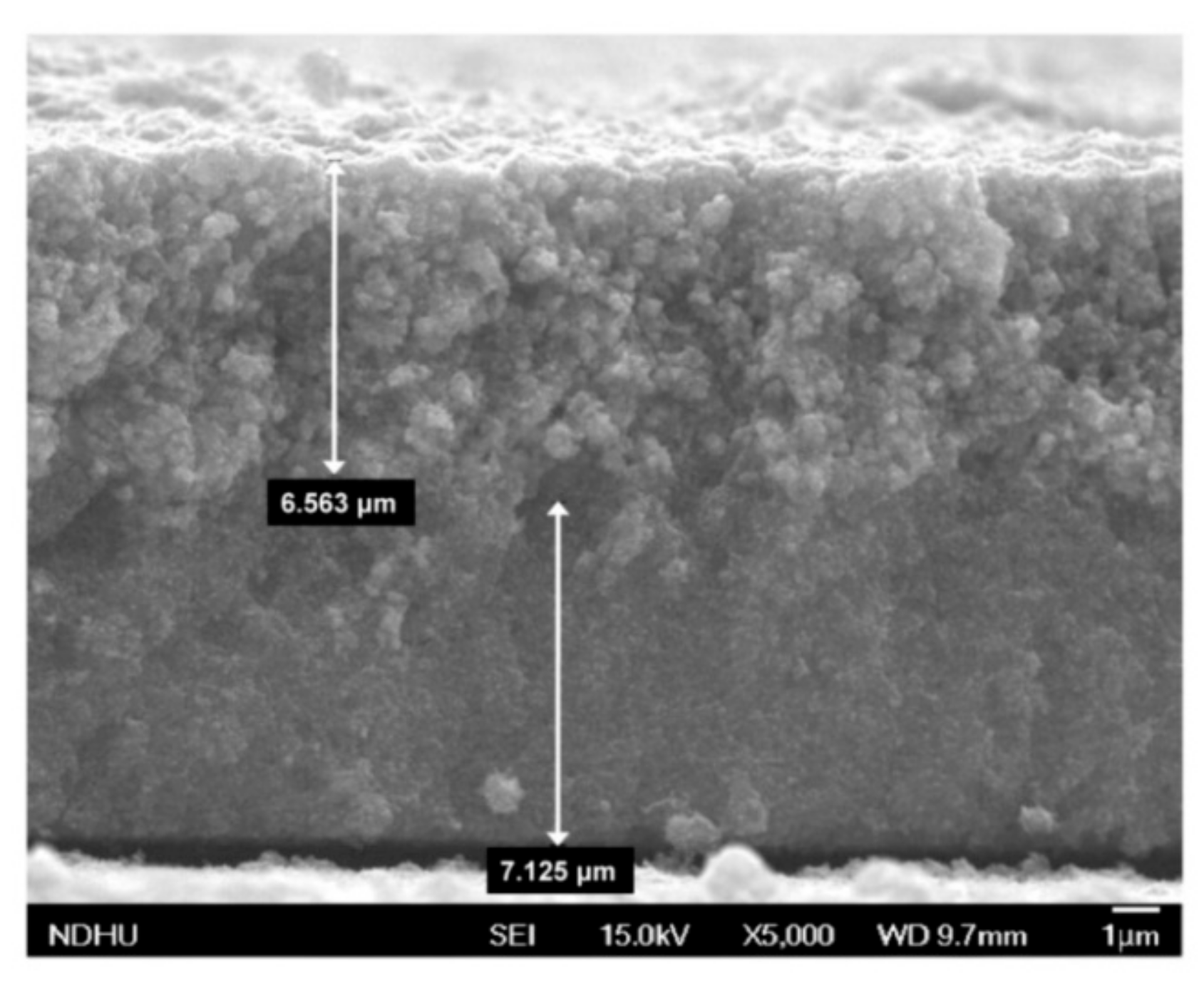
Figure 3.
The EDS results of the (a) TiO2, (b) TiO2–NiO (99:1), (c) TiO2–NiO (98:2), and (d) TiO2–NiO (97:3) working electrodes.
Figure 3.
The EDS results of the (a) TiO2, (b) TiO2–NiO (99:1), (c) TiO2–NiO (98:2), and (d) TiO2–NiO (97:3) working electrodes.

Figure 4.
The XRD analysis results of various working electrodes.

Figure 5.
The (a) O1s and (b) Ti2p XPS analysis results of various working electrodes.

Figure 6.
The full spectrum XPS analysis results of various working electrodes.
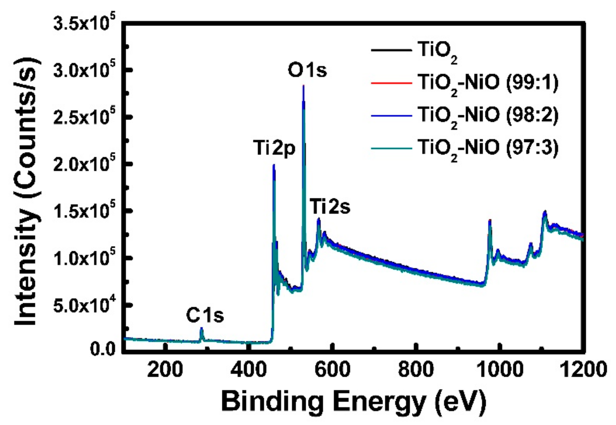
Figure 7.
The J–V curves of the dye-sensitized solar cells (DSSCs) based on various working electrodes.
Figure 7.
The J–V curves of the dye-sensitized solar cells (DSSCs) based on various working electrodes.

Figure 8.
The incident photon-to-electron conversion efficiency (IPCE) results of the DSSCs based on various working electrodes.
Figure 8.
The incident photon-to-electron conversion efficiency (IPCE) results of the DSSCs based on various working electrodes.

Figure 9.
The electrochemical impedance spectroscopy (EIS) results of the DSSCs based on various working electrodes.
Figure 9.
The electrochemical impedance spectroscopy (EIS) results of the DSSCs based on various working electrodes.
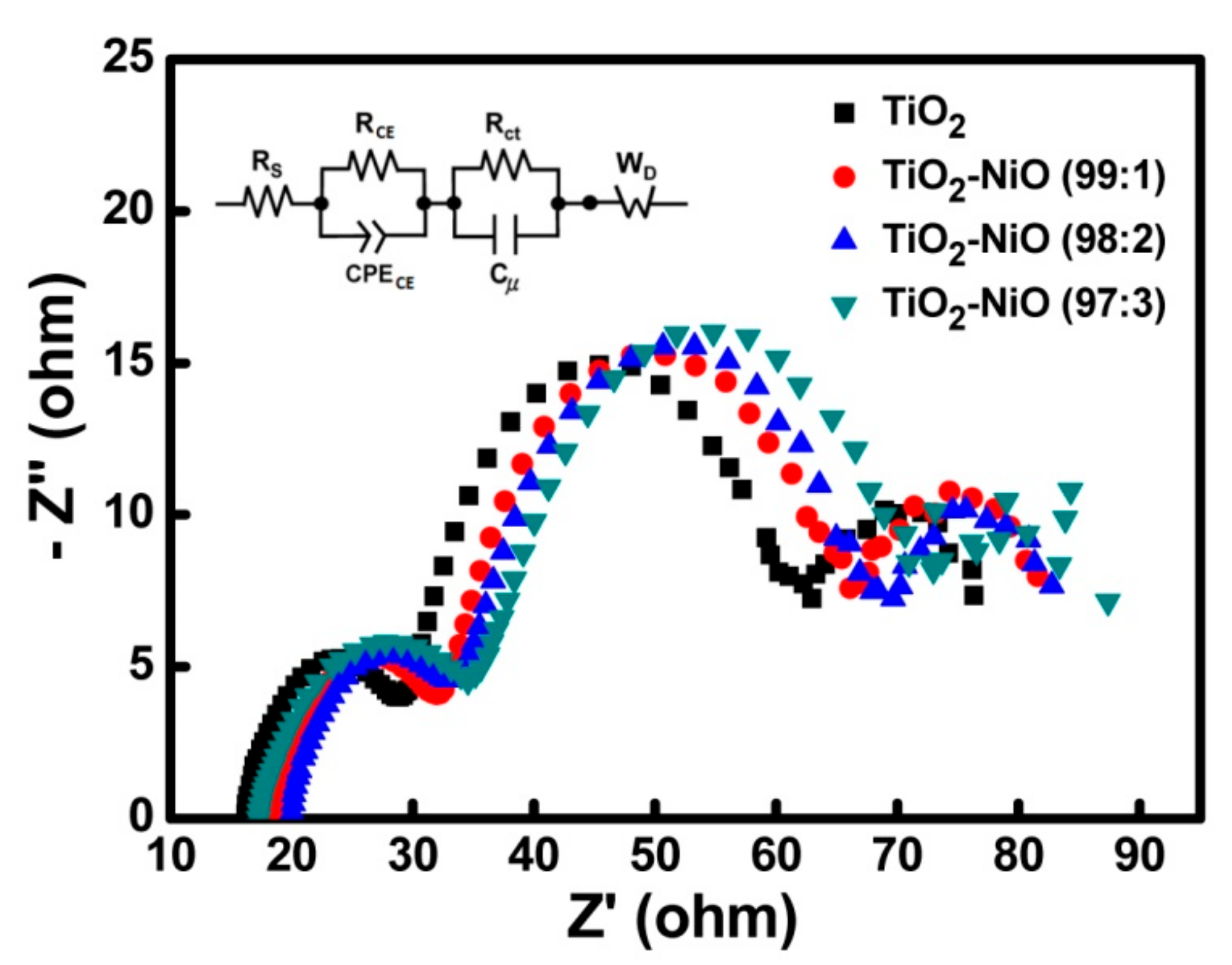
Figure 10.
The (a) intensity-modulated photocurrent spectroscopy (IMPS) and (b) intensity-modulated photovoltage spectroscopy (IMVS) results of the DSSCs based on various working electrodes.
Figure 10.
The (a) intensity-modulated photocurrent spectroscopy (IMPS) and (b) intensity-modulated photovoltage spectroscopy (IMVS) results of the DSSCs based on various working electrodes.
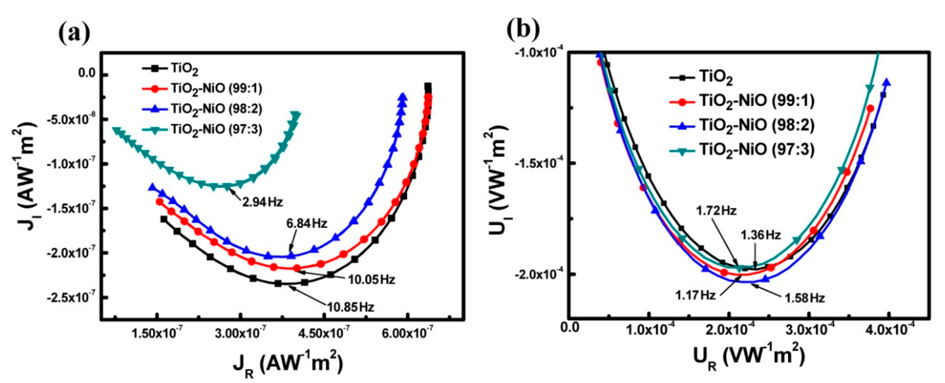
Figure 11.
The mechanism of electron transport in TiO2 and TiO2–NiO working electrodes.


Table 1.
Characteristics of DSSCs fabricated using various working electrodes.
| Working Electrode | JSC (mA/cm2) | VOC (V) | Fill Factor | PCE (%) |
|---|---|---|---|---|
| TiO2 | 16.49 ± 0.05 | 0.73 ± 0.01 | 0.64 | 7.70 ± 0.13 |
| TiO2–NiO (99:1) | 17.15 ± 0.05 | 0.73 ± 0.01 | 0.67 | 8.39 ± 0.14 |
| TiO2–NiO (98:2) | 15.69 ± 0.04 | 0.73 ± 0.01 | 0.67 | 7.67 ± 0.13 |
| TiO2–NiO (97:3) | 15.34 ± 0.05 | 0.73 ± 0.01 | 0.66 | 7.39 ± 0.12 |
Table 2.
The extracted quantitative impedance parameters from the EIS Nyquist plots of the DSSCs based on various working electrodes.
Table 2.
The extracted quantitative impedance parameters from the EIS Nyquist plots of the DSSCs based on various working electrodes.
| Working Electrode | RS (ohm) | RCE (ohm) | Rct (ohm) | WD (ohm) |
|---|---|---|---|---|
| TiO2 | 16.12 | 10.74 | 29.94 | 13.28 |
| TiO2–NiO (99:1) | 18.32 | 11.04 | 30.44 | 13.73 |
| TiO2–NiO (98:2) | 19.61 | 11.26 | 31.48 | 14.14 |
| TiO2–NiO (97:3) | 17.15 | 11.78 | 32.50 | 14.39 |
Table 3.
Characteristics of the electron transit time (τd), lifetime (τn), diffusion coefficient (D), and collection efficiency (ηcc) of DSSCs with various working electrodes measured by IMPS and IMVS.
Table 3.
Characteristics of the electron transit time (τd), lifetime (τn), diffusion coefficient (D), and collection efficiency (ηcc) of DSSCs with various working electrodes measured by IMPS and IMVS.
| Working Electrode | τd (ms) | τn (ms) | D (m2/s) | ηcc |
|---|---|---|---|---|
| TiO2 | 14.67 | 116.53 | 3.19 × 10⁻⁹ | 0.87 |
| TiO2–NiO (99:1) | 15.84 | 135.86 | 2.96 × 10⁻⁹ | 0.88 |
| TiO2–NiO (98:2) | 23.25 | 100.42 | 2.01 × 10⁻⁹ | 0.77 |
| TiO2–NiO (97:3) | 54.09 | 92.56 | 8.66 × 10⁻¹⁰ | 0.42 |
© 2020 by the authors. Licensee MDPI, Basel, Switzerland. This article is an open access article distributed under the terms and conditions of the Creative Commons Attribution (CC BY) license (http://creativecommons.org/licenses/by/4.0/).
Share and Cite
MDPI and ACS Style
Tsai, C.-H.; Lin, C.-M.; Liu, Y.-C. Increasing the Efficiency of Dye-Sensitized Solar Cells by Adding Nickel Oxide Nanoparticles to Titanium Dioxide Working Electrodes. Coatings 2020, 10, 195. https://doi.org/10.3390/coatings10020195
AMA Style
Tsai C-H, Lin C-M, Liu Y-C. Increasing the Efficiency of Dye-Sensitized Solar Cells by Adding Nickel Oxide Nanoparticles to Titanium Dioxide Working Electrodes. Coatings. 2020; 10(2):195. https://doi.org/10.3390/coatings10020195
Chicago/Turabian StyleTsai, Chih-Hung, Chia-Ming Lin, and Yen-Cheng Liu. 2020. "Increasing the Efficiency of Dye-Sensitized Solar Cells by Adding Nickel Oxide Nanoparticles to Titanium Dioxide Working Electrodes" Coatings 10, no. 2: 195. https://doi.org/10.3390/coatings10020195
Note that from the first issue of 2016, this journal uses article numbers instead of page numbers. See further details here.