Article

Thermal Mode Optimization of Combustion Chamber Walls for Power-Plants Using Semitransparent Porous Ceramics

by
Vladimir G. Merzlikin
1,2,*,
Andrei Bystrov
1,
Vitaly Minashkin
1,
Vladimir N. Marynenko
2 and
Fedor Zagumennov
1,3
1
Plekhanov Russian University of Economics, Stremyanny, 36, Moscow 117997, Russia
2
Moscow Polytechnic University, Bolshaya Semenovskaya, 38, Moscow 111116, Russia
3
Central Institute of Aviation Motors, Aviamotornaya, 2, Moscow 111116, Russia
*
Author to whom correspondence should be addressed.
Coatings 2020, 10(3), 252; https://doi.org/10.3390/coatings10030252
Submission received: 30 January 2020 / Revised: 1 March 2020 / Accepted: 3 March 2020 / Published: 9 March 2020
(This article belongs to the Special Issue Selected Papers from IIKII 2019 Conferences)

Abstract

:
The paper examines control and management by thermal mode of the internal surface of heat-insulated combustion chamber walls for green & efficient diesel and gas turbine engines due to the application of opaque or semitransparent thermal barrier materials (coatings). The authors’ model is devoted to combined radiant heat transfer both inside the heat-insulated combustion chamber and its ceramics walls, which could be scattering and absorbing for penetrating radiant component in the subsurface volume of optically heterogeneous porous material. The influence of thermal conduction, scattering (absorption) and external convective effects on the increase of the internal overheating zone in subsurface layers is simulated under intensive radiation. The unique set of optical, thermal-physical and mechanical properties of structural ceramics, depending on their porosity, were first proposed. The radiation fields of the absorbed energy in the near IR region and the corresponding temperature distributions in the modeled opaque and semitransparent ceramics walls were calculated under a stationary radiant-convective heat load during the active combustion phase at time intervals 0.01…0.1 s (diesel engines) and 10...100 s (turbine ones). In order to control the emission of nitrogen oxides, the authors propose a generation model of NOx, its growth or reduction caused by the management of radiant overheating inside semitransparent heat-insulation in which surface temperature is due to volumetric radiant absorption. It is shown that for semitransparent materials (coatings), the optimal thermal mode is determined first of all by thermal radiant characteristics in near IR at heating small times and it begins to correct at long ones due to the effect of thermal conductivity. This process may be modeled and regulated by the selected microstructural porosity of ceramic heat insulation.

1. Introduction

One of the main directions of development of the global engine building industry is the increase of technical & economic indicators and improvement of the environmental performance of the compression ignition and turbine engines. This paper is devoted to the physical modeling and mathematical simulation of the characteristics of complex convective and radiant heat exchange for the coated combustion chamber (CC) wall using the semitransparent or opaque thermal barrier (heat-insulating) materials (TBMs) and coatings (TBCs).
The authors aim to show the possibility of controlling thermal modes within subsurface zones and near CC wall using semitransparent materials (coatings) in comparison with traditional opaque heat-insulating ones. This ensures NOx emission reduction and heat loss control (determining engine efficiency) through the CC wall at the required level due to the formation of a lower subsurface temperature gradient (even at possible positive one grad [T(x = 0,t)] > 0 as a result of influence specific optical properties) and appearing the corresponding temperature maximum inside semitransparent media.
The used optical and thermal physical models of these materials depend on their selective structure causing volumetric reflection (absorption) and low heat conductivity due to variable porosity and foreign matter concentrations. Taking into account the semitransparent properties of the CC inner surface is relevant because in many studies a significant effect of radiation is shown in complex heat transfer studied over many decades. The need to consider complex heat transfer with a significant proportion of the radiant component in the CC power-plants operating at elevated temperatures was justified in many works of known scientists for diesel [1,2,3,4,5], turbine engines [5,6,7], power stations, vehicles, aero-engine parts, and in nuclear engineering [8]. Here is the phrase of an American automotive engineer [1], who clearly indicated already in 2019 the trend of research in the modern automotive industry: “… toward higher operating pressures and higher levels of exhaust-gas recirculation in compression-ignition engines, together with the demand for higher quantitative accuracy, has led to renewed interest in radiative transfer in engines.”
Many scientists confirm [5,6,7,8,9,10] the intensive development of TBMs (TBCs) by the global automotive and aerospace industries. Research for decreasing costs and consumed fuel in internal combustion engines and gas turbine have been continuing. Engine efficiency improvement efforts via constructional modifications are increased today; for instance, parallel to the development of advanced technology ceramics, ceramic coating applications in engines grow rapidly. But in many studies, ceramics were not considered in terms of their semitransparent properties. In the special issue of “Thermal Barrier Coatings” of journal “Coatings” in 2019 on the modern research trends, the presented articles also did not reflect the development of scattering (absorbing) materials and coatings [11].
The authors have repeatedly noted in their previous works [9,10] in 2007–2017 that despite the legendary developments of CC walls coated by ceramic as a semitransparent substance in their current researches, this factor is not considered. This is strange because there are numerous developments of opaque and semitransparent heat-shield composites for aerospace vehicles of American and Soviet engineers [12,13,14] since the 1960s.
So, in most current works, the optics of ceramic heat-insulating materials and coatings have not become the subject of research [1,3,15,16,17,18,19]. Without knowledge optics of material, the empirical techniques for estimating radiant heat transfer parameters are still offered as the base engineering methods of calculation nowadays [2,3]. In the theoretical work [16], a time-periodic model of coated CC thermal conduction changing has been used to calculate the wall temperature swings along the combustion chamber surface within an engine cycle. In other experimental work [17], indirect experimental estimations of convective fluxes dynamics (by high-speed photo registration) are used to offer quality models of thermal modes for heat-insulating ceramic coatings of diesel CC walls. However, in these works, there is no mention of the radiant penetrating component of the total heat flux and the semitransparent properties of the exposed TBMs (TBCs). Instead, the partial absorption of total heat fluxes (without separation convective and radiation components) in the subsurface zone of exposed materials was modeled as an effect due to the influence of porosity [18] without including the optical factor of the heat transfer analysis.
This is a repetition of the introduced famous semi-empirical Annand’s formulas [2] and its modifications [3], in which the separation of radiant fluxes by the wavelength spectrum was also absent. Thus, fundamental physical analysis of radiative-conductive heat transfer for ceramic heat insulation is being replaced by the development of different exotic models of subsurface heat conductivity and only surface reflection for all the spectral radiant components of total heat load [16,17,18,19].
Modeled optical characteristics of ceramic thermal insulation must be consistent in the spectrum with the penetrating radiant component, which reaches 50% in CC diesel [2,3] and 40% in CC gas turbine [1,5,6,7] engines. In Russia, theoretical studies have been carried out for simulation of the radiant fluxes (up to 1–2 MW/m2) & emissivity for spectral radiation range 0.4–9 μm of red-hot soot particles causing the formation of a temperature field in the CC walls of different power plants [20]. This radiation is close in its properties to Planck radiation and can be used for theoretical estimates of the absorbed energy function.
In this paper, the authors continue their theoretical and experimental researches on promising types of ceramics with heat insulation properties both for convective fluxes and thermal radiant ones of model CC walls using ceramics with optical and thermal physical parameters due to different porosity [13,21].

2. Materials and Methods

2.1. Physical Modeling of Combined Radiant Heat Transfer for the Heat-Insulated Combustion Chamber

The study of insulating ceramics for combustion chambers of different types of diesel and turbine power-plants has been carried out since the 1970s. Table 1 presents the main properties of the most famous ceramic materials with physical, operational and commercial parameters. When using these materials, the defining characteristic of acceptable thermal insulation was usually the thermal conductivity coefficient with the required characteristics of crack resistance and stress limit coefficients.
Table 1 presents physical and technical characteristics and parameters according to well-known reference books, handbooks and a number of publications [22,23,24,25,26,27]. To understand and highlight the mentioned major features of presented models of semitransparent (volumetric subsurface reflection-columns I–III) and opaque (surface reflection-columns IV, V) materials are shaded in different background colors (rows 7 and 8 for columns I–III and IV, V). Similarly, in Table 2, these materials are marked with the background color.
Nowadays, in the manufacture of many types of industrial ceramic products, sales prices are also an important characteristic. However, the feature of this table is the content of a unique set of optical, thermal-physical and mechanical properties of structural ceramics depending on their porosity. It is difficult to find such a combination of physical, technical and optical data. The set of optical properties is the determining parameter and classifies ceramics by spectral windows revealing semitransparent and opaque TBM (TBC).
Lack of analysis of the influence the materials’ optical transparency window on the heat resistance of the CC ceramic walls was the reason caused the suspension of the active development ceramic ICE at the end of the 20th century [2,3] and did not introduce the concept of a semitransparent ceramics wall [4,9,10] for automotive engineers.
Usually, specified ceramics with different porosities are being studied as effective thermal insulation. However, these material samples could differ significantly primarily in their optical properties and corresponding transparency windows: up to 2–3 μm for semitransparent oxides. Silicon nitride and silicon carbide are almost completely opaque even in the visible range.
So, aluminum and silicon dioxides (columns 1, 2, 3 of the Table 1) will be heated by penetrating short-wave thermal radiation (See Figure 1a: arrows 1-0, 1-1, 1-2, 1-3) in the subsurface volume of the semitransparent wall fully made up of ceramics—TBM layer (a: I). Or another model of semitransparent heat protection can be considered as the same ceramic layer (I) under the metal substrate (a: II) with surface reflection. The substrate may also be any other semitransparent and opaque material. In these cases, there is surface heating by total convection (See Figure 1a,b: graphic arrow 3I) due to flows of soot particles (1a) and combustion products: mostly hydrocarbons molecules (3a) and nitrogen oxides once (5a). Also, this exposed surface, which absorbs the long-wave thermal radiation (arrow 2-1) of the gas atmosphere within individual spectral transparency windows.
The above-indicated nitride and carbide samples will form their heat balance based on surface absorption of all thermal fluxes (See Figure 1b: 1-0, 2-1, 3I) by their exposed opaque layer (b: II) with its surface reflection coefficient R (b: 1-4) of long-wave radiation. This layer may also be an opaque metal substrate (b: II) coated by a two-layer cover consisting of top highly absorbent soot (b: III), which can be deposited on an intermediate semitransparent sublayer (Figure 1b: I).
The authors proposed a model for the generation of nitrogen oxides that can be carried out by using an opaque ceramic based on insulation SiC, Si3N4 due to surface overheating. When using semitransparent materials, subsurface overheating reduces the surface temperature of the inner walls, causing a reduction in the concentration of nitrogen oxides. Contamination of semitransparent material with foreign absorbing particles (for example, at plasma spraying or soot particle in CC) can turn the material opaque.
With the beginning of the combustion process, soot particles are generated and ensure the appearing of short-wave radiation in the range ~1–3 μm with the value of the integral (over the IR spectrum) initial radiant flux q0 (See Figure 1: 1-0) up to 1–5 MW/m2 [1,2,3,5,6,7]. The proportion of radiation in the heat flux reaches ~50% for CC diesel and ~40% for CC turbine engines.
The deposition of soot particles on the exposed inner surface of the CC-coated walls eliminates the benefits of using semitransparent ceramics. However, the well-known Russian engineer R. Kavtaradze experimentally proved that with increasing the rotational speed of the crankshaft, the soot layer burns out decreases [3]. It is apparently related to a reduction of the combustion cycle (firing stroke) and a relative increase of the radiation time from the red-hot soot particles in the engine cylinder. Thus, the use of semitransparent heat-insulating ceramics will be effective for high-speed diesel engines and powerful turbine engines with an essential component of thermal radiation.
To evaluate the optimal characteristics of the thermal mode and temperature fields formed in a semitransparent ceramic thermal insulation, it is necessary to solve the equations of radiant heat transfer and heat conductivity based on simulated or experimentally measured optical scattering and absorption parameters.

2.2. Mathematical Simulation of Thermal Radiation and Temperature Fields

The studied samples of the semitransparent porous ceramic materials based on sintered powders of zirconium, silicon, and aluminum oxides must be corresponding to high constructional and thermal durability. Then, according to the value of the coefficient of thermal expansion, zirconium dioxide becomes the optimal ceramic material. Although these oxides are inferior in stress limit to samples of nitride and silicon carbide (See Table 1). However, in the CC engine, the conditions of complex heat transfer separate the represented ceramics by the transparency windows and the ability to control the absorbed radiation due to structural adjustment, i.e. changes in porosity. As noted above, only the presented oxide ceramics are able to interact with the radiant heat load by their subsurface volume. Taking into account the mechanical and thermophysical characteristics and the maximum width of the optical transparency window up to 3–4 μm, zirconium dioxide is the most demanded ceramics.
However, the optical properties of these ceramic materials and coatings have been poorly studied, primarily experimentally [21,24,27]. These semitransparent materials, unlike opaque ones, are selectively low absorbing and high scattering media in spectral transparent bands of definite wavelength range during an ignited gas mixture in the combustion chamber of high-speed diesel or turbine engines.
In Table 2, the optical and thermal physical characteristics of opaque and semitransparent samples of partially stabilized zirconium dioxide versus its porosity are presented. Samples with the same thermal physical properties and different optical models are represented by different models.
The optical models Mse1…Mse6 describe semitransparent samples of ceramics TBM with small κ = 14 m−1 and high κ = 28 m−1 absorption indexes and also scattering indexes σ changing in the interval 1000–3500 m−1. Opaque TBM is presented by Mop7 with very high volumetric absorption κ and with only surface reflection by not more than 30%.
Falling radiation penetrates through these media on a distance up to several millimeters in the range of wavelengths ~1–3 μm. This penetration is determined by the volumetric reflectivity r(x), the transparence τ(x) and the absorption a(x), which is dependent on scattering σ and absorption κ indexes for a given semitransparent medium. These indexes define fractions of radiation scattering and absorption per length unit of the semitransparent material in the one-dimensional model of radiation transfer.
In the literature [4,5,6,7,8,24,25], there are discrepant data about the optical property and, as a rule, they correspond only to chemically-rectified powders. Stabilized zirconium oxide is distinguished from this line since it has transparence bands up to 0.4–3.4 μm (corresponding to the spectrum of short-wave radiation 1–3 μm of red-hot soot particles) that has previously been measured and proven by the authors [21]. This penetration causes the volumetric reflection r(x), the transmittance τ(x) and the absorption a(x) coefficients, which is dependent on scattering σ and absorption κ indexes for a given semitransparent material-layer thickness H [10,21]:
a ( H ) + r ( H ) + τ ( H ) = 1 ,
r ( H ) = ( 1 A 2 ) e b H 1 A 2 e 2 b H ,
τ ( H ) = ( 1 e 2 b H ) A 1 A 2 e 2 b H ,
b = κ 2 + p κ σ ,
A = b κ b + κ ,
where b-extinction index is considered as attenuation coefficient, A-albedo is a reflection coefficient of a semi-infinite layer; p is scattering phase function in the two-flux approximation of the solution for the radiative transfer equation with spherical scattering indicatrix p = 1.
Then for semitransparent materials, the inhomogeneous heat conductivity equation has the form (See Figure 1a):
c p ρ T t = x ( K T T x ) + F ( x )
with the boundary conditions and the function F(x)-absorbed energy density of the internal heat source for a plane-parallel layer with thickness H (See Figure 1a):
x = 0 , K T T / x = α T [ T A T ( 0 , t ) ] + ε e f f c 0 [ T A 4 T ( 0 , t ) 4 ] ,
x = H , K T T / x = α T H [ T ( H , t ) T c o o l ] ,
T ( x , t = 0 ) ,
F ( x ) = q 0 ( 1 A ) b 1 A 2 exp ( 2 b H ) { exp ( b x ) exp [ b ( x 2 H ) ] } ,
where q0 is the flux of penetrating thermal radiation incident on the TBM (TBC) surface; cp, ρ, KT-thermophysical characteristics; εeff = (1/ε1 + 1/ε2 − 1)1 -effective emittance for mutually irradiated air and ceramic surfaces with their emissivity factors ε1 и ε2 in the long wavelength range; co-Stefan-Boltzmann coefficient; ρ-density; T(0,t), TA-temperature of the irradiated surface and the environment.
For opaque material F(x) = 0 and the boundary conditions have the form (See Figure 1b):
x = 0 , K T T / x = α T [ T A T ( 0 , t ) ] + ε e f f c 0 [ T A 4 T ( 0 , t ) 4 ] + ( 1 R ) q 0 ,
where R is the surface reflection coefficient from opaque TBM.

3. Results and Discussion

In accordance with the proposed optical models and other properties (See Table 2), the heat conductivity Equation (6), (10) at F(x) ≠ 0 for semitransparent TBM and opaque one (6) at F(x) = 0) with appropriate nonlinear boundary conditions (7)–(9) were solved numerically for a single layer of flat plate for semitransparent (See Figure 1a: I) and opaque (See Figure 1b: II) ceramics under intensive radiant (See 
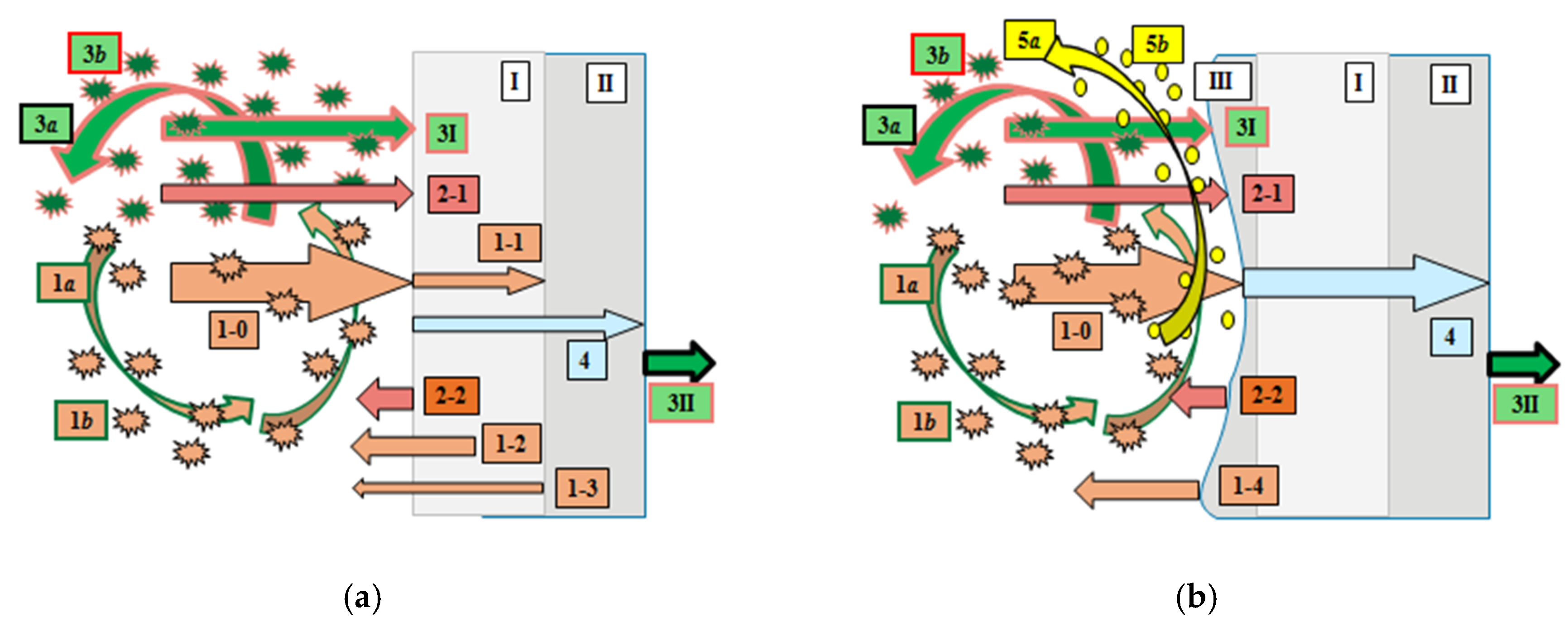
Figure 1a,b: arrow 1-0) and convective (3I) heat fluxes with forced cooling (3II) on the CC walls back surface. The software was developed based on the universal languages Mathcad, Matlab.
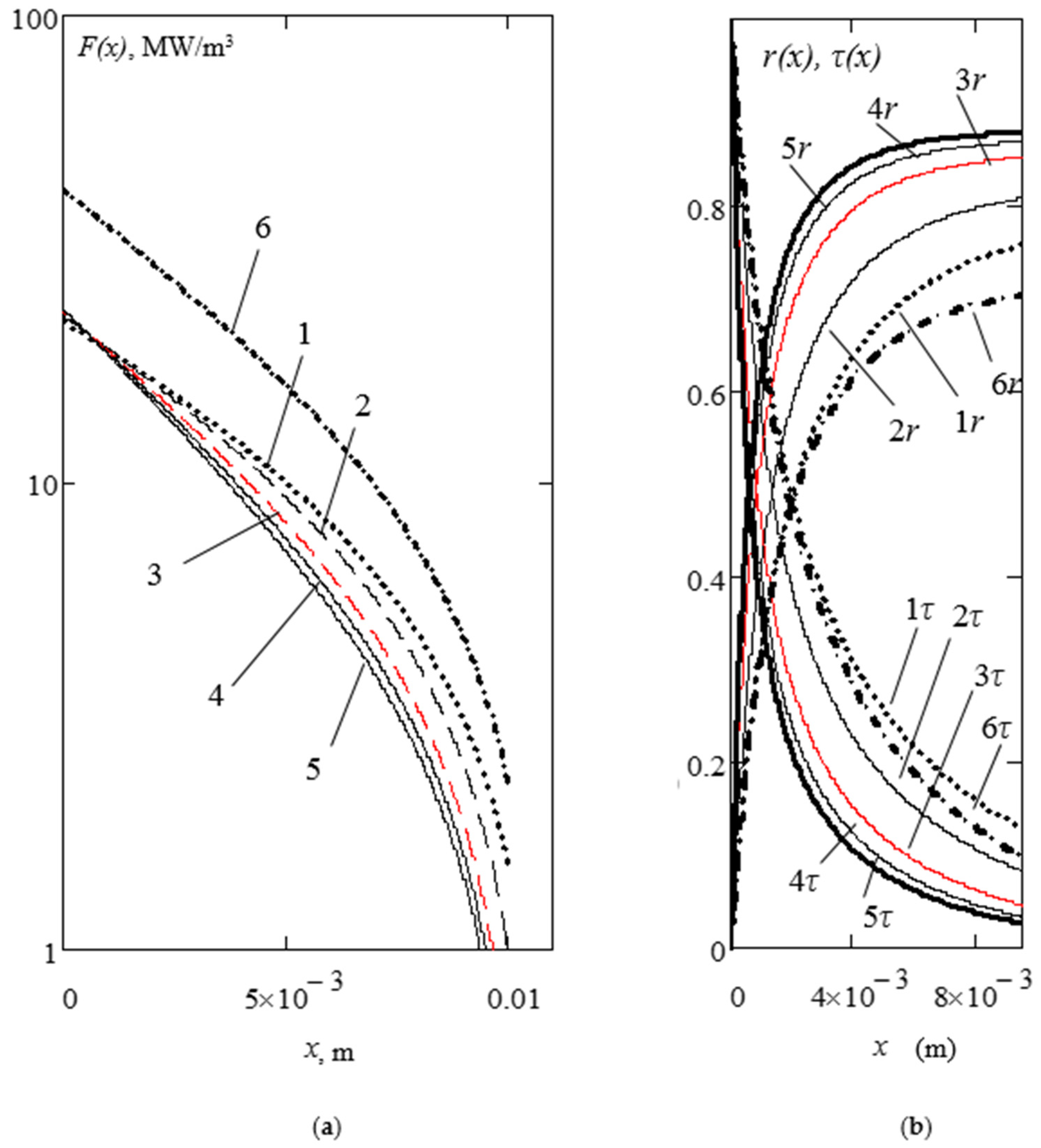
Figure 2 presents: (a) thermal radiation fields of the absorbed energy per time and volume unit F(x) under shortwave radiation flux; and (b) volumetric reflection r(x), transmittance τ(x) coefficients for a plane-parallel semitransparent sample (thickness 0.01 m) at the optical model M(κ/σ−A) with albedo (A, %), absorption (κ, m−1) and scattering (σ, m−1) indexes due to different porosity (See Table 2). Model Mse3 (14/2400-86) is described by the optical characteristics obtained by the authors using the experimental lasers set up with integrating the photometric sphere sandblasted cast aluminum [21].
The following optical models were used to calculate the radiant fields in semitransparent materials M(κ/σ-A): Mse1 (14/1000-79)—curves 1 (Figure 2a,b); Mse2 (14/1500-83)—2; Mse3 (14/2400−86)—3 (experimentally investigated sample Y-PSZ); Mse4 (14/3000-87)—4; Mse5 (14/3500-88)—5, Mse6(28/1000−72)—6. With growth scattering of radiation, there is a decreasing absorption of penetrating radiation: from model Mse1 (σ1 = 1000 m−1) to Mse5 (σ1 = 3500 m−1). Absorption index increasing two times (up to κ2 = 28 m−1 - model Mse6) causes a sharp growth of the absorbed energy (Figure 2a: curve 6) in the subsurface zone. Thus, the efficiency of scattering (volume reflection) processes will substantially depend on the absorption. That’s why the structuring of porous ceramics should be carried out based on chemically pure starting materials.
The calculated radiation fields show important features of semitransparent media: For a more uniform volumetric distribution of absorbed radiant energy, the materials must have small scattering and absorption. Maximum scattering ensures the most reflection and least transmittance for a layer with a given thickness (Figure 2b: model Mse5—curves 5r and 5τ).
To obtain the calculated temperature fields, the nonlinear problem of radiant-conductive heat transfer within the semitransparent monolayer H (CC wall) was solved using the technique developed by the authors of [9,10] and similar calculation-theoretical methods of other works [5,8] for model TBMs samples.
Figure 3 shows an example of simulated complex convective and radiant heating of CC thermal barrier ceramics under constant radiant heat loading ~0.9 MW/m2; at a constant temperature 800 K of gas mixture; heat transfer coefficient αT = 1500 W/m2·K; emittance of gas atmosphere ε1 ~0.4 and for exposed wall as black body 1 (in long-wave range) for ceramic single flat plates with a thickness H =10 mm for time modes of external combine heat action:
-
during t1 = 0.01 s and t2 = 0.1 s for diesel engine (a), and
-
accordingly, for turbine engine CC walls at t3 = 10 s (b) and t4 = 100 s (c)
with convective cooling (αT = 200 W/m2·K) on the CC wall back surface.
The optical characteristics are presented in Table 2 for semitransparent Y-PSZ samples (curves 1…6) with different optical models Mse(κ/σ-A) and opaque (model polluted) samples Mop with surface reflection R = 30%, large absorption and the same thermal characteristics (curves-7).
For a typical heat load inside combustion chamber of high-speed diesel, the use of a semitransparent material (optical model Mse3 [21]) with scattering indices σ = 2400 m−1 at absorption index κ = 14 m−1 (See Figure 3a, curve 3-2) leads to a temperature decreasing by 30 K in surface temperature compared with the non-transparent, opaque one (model Mop7, curve 7-2). The estimates obtained are in good agreement with the qualitative results in [5] and are numerically close to the data in [7]. In the last article, the semitransparent model shows a temperature reduction by 45 K for Y-PSZ of high volumetric reflectance (80%) compared to the same ceramics, but opaque one (for example, polluted by absorbed foreign substance) with low reflectance (20%).
The authors of work [7] described only reflection coefficients without taking into account the influence of scattering and absorption. That’s why the advantages of highly reflective ceramics and the ability to control the thermal regime of TBM by changing its porosity (microstructure) were not considered. The presented semitransparent ceramics correspond to the models Mse2-Mse3 with porosity P~9–18% (See Table 2).
As in well-known work [5], in Figure 3b,c, for turbine CC, the subsurface temperature maximum begins to form at a depth of several millimeters with a stationary total heat load up to 2 MW/m2 with a 50% fraction of the penetrating short-wave radiant component during prolonged heating for more than 10 s. In a semitransparent material, subsurface radiant overheating can cause a temperature maximum comparable in magnitude to the surface temperature of an opaque ceramic. A decrease in surface temperature during prolonged heating can reach hundreds of degrees (See Figure 3b: curves 6-3 and 7-3; Figure 3c: curves 3-4,…, 6-4 in contrast 7-4). Thus, the subsurface zone of the semitransparent material will cause radiant overheating and the accumulation of radiant energy part of the total heat flux due to the optimal selection of the optical models determined by the structure of TBM (TBC).
The interest for ceramic TBMs (TBCs) in particular is determined by the creation of a new class of semitransparent coatings capable of absorb and accumulating a radiant component of thermal flux in the near IR (~1 ÷ 3 μm) within subsurface volume during the combustion of a fuel blend in CC of diesel and turbine engines. Simultaneously, the long-wave radiant component (~3–5 μm) in the mid-IR range corresponds to a lower emission heat flux in comparison with the short-wave component one.
Engine makers did not take into account optical properties (near IR) of heat-insulating materials and coatings. That is why the traditionally radiant components of the heat flux have been considered as absorbed ones on the CC boundary internal surface as well as convective component.
At small heating times (for one full cycle of the piston’ movement in the diesel CC), high scattering causes a surface temperature decrease by 10–20 K at t1 = 0.01 (See Figure 3a, curves 3-1 in comparison with 7-1). For t2 = 0.1, the temperature decreases up to 70 K (See Figure 3a, curves 1-2, ..., 4-2 in comparison with 7-2) due to volumetric radiant overheating. Curves 5-1 and 5-2 for a semitransparent material correspond to the thermal mode of an opaque TBM, but it represents an exotic variant for physical modeling and mathematic simulation of optical properties with little influence of thermal conductivity.
However, at large heating times, 3rd thermal mode t3 = 10 s (when the influence of the thermal conductivity coefficient begins to appear), there is more extensive subsurface overheating during deceleration of the growth surface temperature and decreasing (in modulus) of the negative temperature gradient (See Figure 2b: curves 1-3,…, 6-3). Under these thermal modes, the overheating of an opaque material surface exceeds by 200 K (curves 7-3) the temperature within the thickness of a semitransparent TBM (curves 1-3,…, 6-3). Of course, this level of overheating is unacceptable and this led to the use of semitransparent oxides even without any theoretical justification.
A subsurface temperature maximum forms in ceramics at long periods of fuel combustion for hot sections of a gas turbine engine, for example, at 4th thermal mode t4 = 100 s (See Figure 3c: curves 1-4,…, 6-4). In this physical model, the influence of the thermal conductivity coefficient begins to prevail (in comparison with scattering), and the subsurface overheating zone increases with constant adsorption index. The scattering index (over a wide range of its changes) can be modeled by the microstructure (porosity) for control thermal modes under penetrating intensive thermal short-wave radiation.
The intense intrinsic reradiation of the exposed ceramic surface in the long-wavelength region of the spectrum with a high black factor also stimulates internal overheating by short-wave radiation.
Also, simulation results show that, in such media, not forming surface temperature, but a generated subsurface maximum could be used to ensure optimal thermal modes under intensive short-wave infrared radiation. Internal walls do not achieve these extreme temperatures using semitransparent materials (coatings). This allows us to decrease surface temperature for the internal surface combustion chamber and to limit the formation of toxic nitrogen oxides.
Thus, the generation and emission of nitrogen oxides NOx could be controlled caused by the management of radiant overheating inside semitransparent heat-insulation in which surface temperature is decreasing due to volumetric radiant absorption. It was shown that the subsurface radiation and temperature fields are determined first of all by optical characteristics, which can be modeled using the selected microstructural porosity of ceramic thermal insulation.
For these cases, the required porosity of ceramics can be limited by P ~15%. The selective shape and size of pores (or scattering particles) can become a technological parameter that determines the optical model with varying scattering and absorption characteristics at constant porosity. The value of the heat conductivity coefficient will not change significantly.
The presented methodology for modeling and control of subsurface radiant and temperature fields in semitransparent scattering and absorbing ceramic materials may be the basis for studying the thermal modes under pulsed and periodic exposure. Suggested models of physical and mathematical modeling will be needed when creating heat-insulating materials and coatings in various fields of science and technology, in the automotive and aerospace industry, shipbuilding, etc.

4. Conclusions

The structural ceramics presented (as ceramic thermal insulation) differ in their thermal modes of heat transfer: with a conductive (silicon carbide and silicon nitride) mechanism and radiation-conductive (metal and silicon oxides) one (See Table 1 and Table 2). Thus, with the generated intense radiant component in CC, semitransparent oxides become the more preferred TBM in contrast to the opaque one.
The structural composition of the semitransparent ceramics ZrO2 (Y-PSZ), Al2O3, and SiO2 can ensure the necessary scattering and absorption to control the temperature profile in the exposed ceramic wall. However, with approximately the same effect of optics on heat transfer through the ceramic wall, the linear expansion factor becomes a determining parameter, because it is the closest in terms of this coefficient to metal substrates. Due to its high linear expansion factor coefficient ZrO2 stabilized by 5–20% Y2O3 is most widely used for the production of ceramic coatings with operating temperatures up to 2500 K. Moreover, the crack resistance and stress limit characteristics for other ceramics are close to each other (See Table 1).
Also, among the many materials, zirconia has a unique upper bound of the spectral transparency window. Thus, it can be confidently stated that the full radiant flux of red-hot soot particles will be absorbed in the subsurface zone and not on the exposed surface of ceramic heat insulation.
Reduced scattering leads to greater transparency of the irradiated medium and absorption in a wider subsurface zone. Of course, with low absorption, i.e. in the absence of absorbing impurities. Thus, the production of heat-resistant semitransparent ceramics requires an initial powder in a high degree of purity up to 96–99%.
Convective fluxes growth (at lowering of the exposed surface temperature) also stimulates subsurface overheating with a positive temperature gradient. A decrease in the temperature of the gas atmosphere and the inner surface of the CC walls will contribute to the sink of conductive heat to the exposed surface from the overheated subsurface zone.
The subsurface overheating effect is observed both in semitransparent materials and in translucent natural environments, for example, in snow and water covers [28,29].
The authors believe that the use of modern methods for the manufacture of ceramic materials and coatings can ensure the construction and build-up of the required microstructure of TBMs or TBCs for optimal conditions of the thermal mode selection under the influence of a powerful radiant convective load.
The next generation of green and efficient vehicle power-plants will be determined by the rapidly growing development of advanced technology of semitransparent ceramics allowing to optimize its thermal modes.
Commercial value releases zirconium oxides as the most expensive material (See Table 1). However, this is not an obstacle, given the benefits of using new types of semitransparent TBM (TBC) to create heat-resistant parts for hot sections of gas turbines and piston heads of diesel engines.

Author Contributions

Conceptualization, V.G.M. and V.M.; methodology, V.M. and A.B.; software, F.Z.; validation, V.G.M., V.M. and F.Z.; formal analysis, A.B.; investigation, V.G.M. and F.Z.; resources, V.M. and V.N.M.; writing—review and editing, V.G.M., F.Z. and A.V.; project administration, V.M. and V.N.M. All authors have read and agreed to the published version of the manuscript.

Funding

This research received no external funding.

Acknowledgments

Mikhail Belyaev, Ksenia Nechai for assistance in search, analysis, systematization of bibliometric data; Sergey Klochkov for participating in laboratory optical diagnostics of materials.

Conflicts of Interest

The authors declare no conflict of interest.

Abbreviations

CCCombustion Chamber
TBMThermal Barrier Material
TBCThermal Barrier Coating
Y-PSZYttria-Partially Stabilized Zirconia (ZrO2 +8%Y2O3)
NOxMolecules of Nitrogen Dioxides

References

  1. Paul, C.; Fernandez, S.F.; Haworth, D.C.; Modest, M.F. A detailed modeling study of radiative heat transfer in a heavy-duty diesel engine. Combust. Flame 2019, 200, 325–341. [Google Scholar] [CrossRef] [Green Version]
  2. Woschni, G.; Spindler, W.; Kolesa, K. Heat insulation of combustion chamber walls—A measure to decrease the fuel consumption of IC Engines. SAE Int. Paper 1987, 870339. [Google Scholar] [CrossRef]
  3. Kavtaradze, R. Chapter 7. Thermal insulation of parts and its effect on the working process of a piston engine. In Lokal’nyy Teploobmen v Porshnevykh Dvigatelyakh [Local Heat Transfer in Piston Engines], 2nd ed.; Bauman MGTU Publ.: Moscow, Russia, 2016; pp. 382–423. [Google Scholar]
  4. Makino, T.; Kunitomo, T.; Sakai, I.; Kinoshita, H. Thermal radiation properties of ceramic materials. Heat Transf. Jpn. Res. 1984, 13, 33–38. [Google Scholar]
  5. Siegel, R. Internal radiation effects in zirconia thermal barrier coatings. AIAA J. Thermophys. Heat Trans. 1996, 10, 707–711. [Google Scholar] [CrossRef] [Green Version]
  6. Wang, J.I.; Eldridge, S.M.; Guo, F. Comparison of different models for the determination of the absorption and scattering coefficients of TBCs. Acta Mater. 2013, 64, 402–409. [Google Scholar] [CrossRef]
  7. Lim, G.; Kar, A. Modeling of thermal barrier coating temperature due to transmissive radiative heating. J. Mater. Sci. 2009, 44, 3589–3594. [Google Scholar] [CrossRef]
  8. Petrov, V.A. Thermoradiation characteristics of refractory oxides upon heating by concentrated laser radiation. High Temp. 2016, 54, 186–196. [Google Scholar] [CrossRef]
  9. Merzlikin, V.; Gutierrez, O.M.; Sidorov, O.; Timonin, V. New selectively absorbing and scattering heat-insulating coatings of the combustion chamber for the Low-Heat-Rejection Diesel. SAE Tech. Paper 2007. 2007-01-1755. [Google Scholar] [CrossRef]
  10. Merzlikin, V.G.; Parshina, S.A.; Garnova, V.Y.; Bystrov, A.V.; Makarov, A.R.; Khudyakov, S.V. Rig test of diesel combustion chamber with piston coated optically simulated semitransparent PSZ-ceramic. In Proceedings of the13th International Conference on Engines and Vehicle, Naples, Italy, 4 September 2017. Paper 17ICE-0103/2017-24-0129. [Google Scholar]
  11. Thermal Barrier Coatings. Special Issue of “Coatings” (ISSN 2079-6412). Huibin Xu, Ed. 2018. Available online: https://www.mdpi.com/journal/coatings/special_issues/TBCs (accessed on 15 February 2020).
  12. Viskanta, R.; Grosh, R.J. Heat Transfer in a thermal radiation, in absorbing and scattering medium. In International Development in Heat Transfer; Part IV; ASME: New York, NY, USA, 1961; pp. 820–828. [Google Scholar]
  13. Boeringer, J.C.; Spindler, R.J. Radiant Heating of Semitransparent Materials. AAIA J. 1963, 1, 84–88. [Google Scholar] [CrossRef]
  14. Avduevskiy, V.S. Osnovy Teorii Poleta Kosmicheskikh Apparatov [Fundamentals of the Flight Theory of Space Vehicles]; Mashinostroenie Publ.: Moscow, Russia, 1972; 345p. [Google Scholar]
  15. Ganji, D.D.; Sabzehmeidani, Y.; Sedighiamiri, A. Chapter 3. Radiation Heat Transfer. In Nonlinear Systems in Heat Transfer. Mathematical Modeling and Analytical Methods, 1st ed.; Elsevier Science Publ.: Amsterdam, The Netherlands, 2018; pp. 105–151. [Google Scholar]
  16. Caputo, S.; Millo, F.; Cifali, G.; Pesce, F. Numerical investigation on the effects of different thermal insulation strategies for a passenger car diesel engine. Int. J. Engine 2017, 10. [Google Scholar] [CrossRef]
  17. Uchida, N.; Osada, H. A new piston insulation concept for heavy-duty diesel engines to reduce heat loss from the wall. SAE Int. J. Engines 2017, 10, 2565–2574. [Google Scholar] [CrossRef]
  18. Das, D.; Majumdar, G.; Sen, R.S.; Ghosh, B.B. Evaluation of combustion and emission characteristics on diesel engine with varying thickness of PSZ coated piston crown. Int. J. Innov. Res. Sci. Eng. Technol. 2013, 2, 4858–4865. [Google Scholar]
  19. Sankar, V. Thermal Barrier Coatings material selection, method of preparation and applications—A Review. Int. J. Mech. Eng. Rob. Res. 2014, 3, 510–521. [Google Scholar]
  20. Kutergina, N. Issledovaniye Teplovogo Izlucheniya Produktov Sgoraniya Energeticheskikh Ustanovok Metodom Vychislitel’nogo Eksperimenta [Study of Thermal Radiation of Power Plants’ Combustion Materials Using Numerical Experiment Method]. Ph.D. Thesis, Vyatka State University of Russia, Kirov, Russia, 2011. [Google Scholar]
  21. Merzlikin, V.; Bystrov, A.; Smirnov, S.V. Detection technique of the optical and thermoradiative characteristics with compensation effect of reflection and transmittance indicatrices for the semitransparent materials with high subsurface scattering. Proc. IOP Conf. Mater. Sci. Eng. 2019, 613, 012049. [Google Scholar] [CrossRef]
  22. Litovskiy, E.Y.; Puchkelevich, N.A. Teplofizicheskiye Svoystva Ogneuporov [Thermophysical Properties of Refractories]; Metallurgiy Publ.: Moscow, Russia, 1982; 150p. [Google Scholar]
  23. Rutman, D.S.; Toropov, Y.S.; Pliner, S.Y.; Noumin, A.D.; Polezhaev, Y.M. Chapter 3. Technology of refractories and ceramics made of zirconium dioxide. In Tekhnologiya ogneuporov i keramiki iz dioksida tsirkoniya Vysokoogneupornyye Materialy iz Dioksida Tsirkoniya [Highly Refractory Materials from Zirconium Dioxide]; Metallurgiy Publ.: Moscow, Russia, 1985; pp. 66–90. [Google Scholar]
  24. Kalatur, E.; Buyakova, S.; Kulikov, S. Porosity and mechanical properties of zirconium ceramics. J. Silic. Based Compos. Mater. 2014, 66, 31–34. [Google Scholar]
  25. Radzig, A.A. Handbook of Physical Quantities; CRC-Press Publ.: Boca Raton, FL, USA, 1997; 1548p. [Google Scholar]
  26. Babichev, A.P.; Babushkina, N.A.; Bratkovsky, A.M.; Brodov, M.E.; Bystrov, M.V.; Vinogradov, B.V.; Vinokurova, L.I.; Gelman, E.B.; Geppe, A.P.; Grigoriev, I.S. Fizicheskiye Velichiny. SPRAVOCHNIK [Physical Quantities. Handbook]; Grigoriev, I.S., Meilikhova, E.Z., Eds.; Energoatomizdat Publ.: Moscow, Russia, 1991; p. 1232. [Google Scholar]
  27. Moskal, G.; Mendala, B. Characterization of microstructure and properties of TBC systems with gradient of chemical composition and porosity. Arch. Metall. Mater. 2008, 53, 945–954. [Google Scholar]
  28. Merzlikin, V.G.; Ilushin, Y.A.; Olenin, A.L.; Sidorov, O.V.; Tovstonog, V.A. The criterial optics of oceans and glaciers with technogenic pollutions. AIP Conf. Proc. 2017, 1810, 120004. [Google Scholar] [CrossRef] [Green Version]
  29. Koh, G.; Jordan, R. Sub-surface melting in seasonal snow cover. J. Glaciol. 1995, 41, 474–482. [Google Scholar] [CrossRef] [Green Version]
Figure 1. Radiant heat transfer for the model of coated CC walls (or fully made of ceramics) with volumetric (a) and surface (b) reflection under the following fluxes: short wavelength radiation one (1-0—falling radiation; 1-1—absorbing one; 1-2—reflected flux by a subsurface zone of the top layer (I) and by a substrate (II) with its surface reflection––1-3) and long wavelength radiation one, including heat fluxes: 2-1 (gas atmosphere) and 2-2 (exposed ceramics); convective heat loading—3I (from soot particles-1a; hydrocarbons molecules–3a; nitrogen oxides once–5a) and wall back surface cooling—3II; -thermal conductive—(4). (a): semitransparent materials—(I) with opaque (semitransparent) substrate––(II); (b): combine heat-insulation in the forms of a single opaque layer (b: II) with surface reflection (1-4) or layer substrate (b: II) coated by deposition (b: III) of soot particles (1b) under an intermediate semitransparent (b: I) layer.
Coatings 10 00252 g001
Figure 2. One-dimensional distribution of absorbed radiant energy per time and volume unit F(x) of short wavelength radiation (a) and (b)-volumetric reflection r(x), transmittance τ(x) coefficients vs thickness x for a single semitransparent layer for optical models Mse1—curves 1, Mse2—2, Mse3—3 (experimental optics—red curves), Mse4—4, Mse5—5, and Mse6—6 (See Figure 1b; Table 2).
Coatings 10 00252 g002
Figure 3. Temperature profiles T(x,t) in CC ceramic walls (full made from thermal barrier materials) using Y-PSZ with the porosities causing the selection of optical models for semitransparent Mse1,…,Mse6 (See Table 2, Figure 1a) and opaque Mop7 (b) TBM under modeling stationary heat load at thermal modes due to heating times t1 = 0.01 s and t2 =0.1 s for diesel engines (See left side of this Figure, a) and turbines once: at t3=10 s (See middle side, b); t4=100 s (See right side, c). The following abbreviation of denoted curves was used, which includes the numbers of optical models together with designation records of thermal modes 1,…, 4 (bold and the underline for next digital notations): (a)–models Mse3, Mop3, Mop7 at 1st mode t1-curves 3-1, 5-1, 7-1; Mse1—Mop7 at t2-curves 1-2,…,7-2; (b)–Mse1—Mop7 at t3-curves 1-3,…,7-3; (c)–Mse1—Mop7 at t41-4,…,7-4.
Coatings 10 00252 g003
Table 1. Physical, technical characteristics and commercial parameters of industrial ceramic TBMs.
##IIIIIIIVV
1Type of structural ceramicsZrO2
(Y-PSZ)
Al2O3SiO2SiCSi3N4
2Crack Resistance, MPa·m1/24–133.2-3.55
3Stress Limit, MPa425300-600400
4Linear Expansion, 1/K11·10−68.6·10−64·10−64·10−63.5·10−6
5The porosity of
industrial samples, %
<30<40<14<5<5
6Operating Temperatures, °C1500–25001000–20001000–170013501400–1750
7Optical reflection model Magnitude of reflection, %Volumetric
<99
Surface
<20–30
8Spectral Window, μm~0.4–3.4 *~0.4–2.5~0.4–2.0~0.4–1.0
9Thermal conductivity, W/m·K1–2.5259200150
10Source raw materialZirconAlumina and
silicate sands
Artificial substances
11Product Price
(Powders), $/kg
40–8020–305–10210–50
* Optical measurements by authors [21].
Table 2. Optical, thermal and structural characteristics for model & experimental (*) samples of opaque (semitransparent) ceramics based on yttria partially stabilized zirconium dioxide (PSZ) ZrO2 + 8%Y2O3 versus its porosity.
Type of TBM: Optical Model/Numbers of Curves on Figure 2 and Figure 3PorosityDensityConductivityOptical Indexes (Coefficients)Albedo
A, R, %
TypeValue
P, %
ρ,
kg/m3
(a) KT,
W/m·K
ScatteringAbsorption
κ, m−1σ, m−1
Model of Opaque MaterialEspecially Dense Samples060001.70Model Mop7 for Opaque Material with Surface Reflection Coefficient
Mop7/#7>104030
Models of Semitransparent MaterialsVolumetric Reflection for
Models: Mse1, Mse6, Mse1…Mse5
Mse1/#114100079
Mse6/#628100072
Mse2/#2Compact955001.2514150083
Mse3/#3 (*)Compressed1849001.1014 (b)2400 (b)86 (b)
Mse4/#4Middle Porous4037000.7014300087
Mse5/#5Highly Porous6024000.5014350088
(a) Measurements at temperature 900K [23,24]. (b) Authors’ measurements using the experimental optical set up with laser sounding [21].

