Article

Design of Corrosion Protective and Antistatic Hybrid Sol-Gel Coatings on 6XXX AlMgSi Alloys for Aerospace Application

by
Cecilia Agustín-Sáenz
*,
Patricia Santa Coloma
,
Francisco J. Fernández-Carretero
,
Fabiola Brusciotti
and
Marta Brizuela
TECNALIA, Basque Research and Technology Alliance (BRTA), Mikeletegi Pasealekua 2, 20009 Donostia-San Sebastián, Spain
*
Author to whom correspondence should be addressed.
Coatings 2020, 10(5), 441; https://doi.org/10.3390/coatings10050441
Submission received: 3 April 2020 / Revised: 23 April 2020 / Accepted: 27 April 2020 / Published: 30 April 2020
(This article belongs to the Special Issue Corrosion Science and Surface Engineering)

Abstract

:
An inorganic–organic coating based on glycidyl-functionalized silica and zirconia was synthesized by sol-gel technology to protect three types of AlMgSi (6XXX series) alloys against corrosion in aerospace applications. Different parameters such as the solid content, the organic/inorganic ratio of the sols and the deposition conditions were studied with the aim to achieve a tradeoff between the corrosion protection, antistatic performance and low vacuum-induced outgassing. Those parameters directly influence the thickness and the density of the coatings, and therefore the barrier effect against corrosion and the contact electrical resistance, which are affected in opposite ways. To obtain a low contact electrical resistance, silver nanowires (NW) with a high aspect ratio were loaded in the sol-gel matrix with the aim to create a conductive path through the hybrid coating with a low concentration of NWs. The coatings were adapted for AA6063, AA6061 and AA6082, and they all showed an outstanding anti-corrosion performance in different artificial weathering tests, whereas electrochemical impedance spectroscopy permitted the identification of the most critical parameters affecting water uptake. An antistatic performance was demonstrated by the low contact electrical resistance of the coated AA6061 and AA6063 alloys, although the incorporation of NWs showed a detrimental effect on the corrosion protection compared with the unloaded coating.

1. Introduction

AlMgSi (6XXX series) alloys are widely used as structural materials in the aerospace and automobile industries owing to their favorable strength-to-weight ratio and their relatively high corrosion resistance [1]. Because the level of strength achievable by adding only Si is low, Mg is also added to improve the strength through the formation of β-phase (Mg2Si) precipitates. Even higher mechanical properties, strength and ductility of that heat treatable alloys can be obtained by either alloying with a low amount of Cu or adding an excess amount of Si, considering the stoichiometry of Mg2Si precipitates [2]. Depending on the alloying elements and their ratio, AlMgSi alloys have been divided in three groups [3]. The first and second groups (e.g., AA6063 and AA6061 respectively) are alloys with balanced amounts of Mg and Si. Alloys of the first group contain low weight percentage of Mg and Si (0.8–1.2%), while alloys of the second group contain them in a weight percentage > 1.4% and Cu is also added to improve the mechanical properties. The alloys of the third group (e.g., AA6082) contain excess of Si, which is also responsible for age hardening (unbalanced alloys). In general, the approaches to improve mechanical properties through microstructural modifications result in detrimental changes to corrosion properties. Therefore, the effect of both copper content [2,4,5,6] and Si excess [2] on the susceptibility to corrosion resistance have been discussed.
In aerospace applications, these alloys are normally passivated with conversion coatings containing hexavalent chromium, although recently high efforts for its replacement are being performed, resulting in the use of trivalent chromium, silicate, vanadate, molybdate, permanganate and zirconate compounds [7,8]. These coatings convert the electrochemically active metal surface to a passive state by forming a mixed metal oxide layer. Organic and hybrid coatings synthesis technologies have also attracted many researchers because of environmental compliance and outstanding corrosion protection of a wide range of metals and alloys. Among them, sol-gel method is a versatile approach for coating material design due to the possibility of combining inorganic and organic moieties covalently bonded through inorganic polycondensation and organic polymerization reactions taking place simultaneously [9].
In the design of parts for aircraft and spacecraft industries, the phenomenon of static electricity must also be considered. The accumulation of extreme static charges on an aircraft, generated by the interaction between the outer surface of the aircraft and external environmental phenomena (air particles, ice, hail, dust, volcanic ash, lightning strike) or triboelectric charging, can lead to failure of parts and eventually to severe explosion or radio communication failure [10,11]. The huge current caused by lightning travels through the least resistant parts of the aircraft structure [12]. It is important to create a conductive path of low resistance over the entire aircraft exterior to prevent the lightning charge from attaching to several parts and then arcing or sparking. Surface finish must be also considered. If corrosion protective or decorative coatings are too thick, they may disrupt the conductive path with consequential increasing of surface resistance and risk of greater damage.
High vacuum is another crucial factor when designing materials for space environment, due to the induced material outgassing. Outgassing is referred to as the release of gaseous species from a specimen under high vacuum conditions. Outgassing materials can be harmful to the performance of spacecrafts since expelled gases result in contamination, which indeed can affect the performance of optical instruments, solar cells, thermal control surfaces, ultraviolet astronomy, etc.
In a recent work of the authors [13], a hybrid organic-inorganic sol-gel coating material with anticorrosion performance was developed and applied on zinc coated steel. The sol-gel synthesis was based on the incorporation of organic precursors in an epoxy functionalized-silica-zirconia hybrid matrix. The present work has focused on the improvement and adaptation of the bi-phenol containing sol-gel formulation, which had resulted in the composition with the highest corrosion resistance properties, for providing enhanced corrosion protection on AlMgSi alloys in compliance with aerospace applications. In particular, one alloy of each group has been selected, namely AA6063 from the first group, with low content of Mg and Si (tensile strength ~ 245 MPa), AA6061 from the second group, with medium content of Mg and Si and further Cu addition (tensile strength ~ 310 MPa), and AA6082 from the third group, with unbalanced Si (tensile strength ~ 345 MPa). AA6061 exhibits high corrosion resistance and excellent extrudability and AA6063 is widely used owing to its extrudability. Recently, AA6061 and AA6063 are being replaced by AA6082 in some aerospace applications due to its higher strength to weight ratio [14]. With the aim to reach a tradeoff between corrosion protection, low electrical resistance, low water uptake and low outgassing, different approaches have been tackled for the three alloys: (i) coating thickness has been studied on AA6061, to obtain the required corrosion protection with the minimum amount of material and ensure low electrical resistance, (ii) equivalent solid concentration and inorganic/organic ratio of sol formulation were adapted to improve AA6082 protection, (iii) the sol-gel matrix was modified with Ag nanowires to create a conductive path and decrease the surface resistance of AA6063. The effect of coating density, thickness and roughness on surface electrical resistance (measured according to MIL-DTL-81706B [15]) and on corrosion performance (evaluated through electrochemical impedance spectroscopy) has been determined. Durability has been assessed, following aerospace industry specifications, through neutral salt spray, thermal cycling and damp heat exposure, in comparison to Cr VI and Cr III conversion coatings. A partial vacuum-induced outgassing of the coatings has been studied according to the ECSS-Q-ST-70-02C standard [16] to check the suitability for space applications.

2. Materials and Methods

2.1. Materials

N-propanol (extra pure, > 99%) solvent was purchased from Scharlab, S.L. (Sentmenat, Spain), Si alkoxide tetraethyl orthosilicate (TEOS, purity 98%) as silica precursor was purchased from Acros Organics (Geel, Belgium) and Si epoxy functionalized-alkoxide glycidoxypropyl trimethoxysilane (GPTMS, purity > 98%) as hybrid precursor was purchased from Sigma-Aldrich (St. Louis, MO, USA), as well as the organic precursor bisphenol A (BPA, purity 97%). All of them were used as received. Sulfuric acid (H2SO4, purity 95–97%) was purchased from Scharlab, S.L. and it was used to prepare a 0.1 M solution in deionized water which worked as catalyst.
Zirconium (IV) n-propoxide (TPOZ, 70% in n-propanol) was used as zirconia precursor and purchased from Acros Organics; acetyl acetone (AcAc, purity 99%), used as complexing agent, was provided by Scharlab, S.L., and both were used as received.
Ag nanowires (NW) were purchased from ACS Material, Pasadena, CA, USA, (AgNW, 20 mg/mL in 1-propanol) and were 50 nm thick (diameter) and 200 μm long.
Solutions of sodium fluorosilicate, 2-(2-butoxyethoxy) ethanol, 4-nonylphenyl-polyethylene glycol and anionic surfactant from Turco Española, S.A. (Barcelona, Spain) were used for preparing alkaline degreasing bath. Solution of sodium bifluoride and ferric sulfate from Turco® as well as nitric acid (HNO3, 67% vol) from Sigma-Aldrich were used for preparing acid picking bath.
The Cr VI conversion coating, Alodine 1200S, was purchase from Henkel (Germany), while the Cr III conversion coating, Surtec 650, was purchase from SurTec (Bensheim, Germany).
The substrates used were 1-mm thick sheet of commercial cold-rolled wrought 6082 T6 Al alloy; 1-mm thick sheet of commercial cold-rolled wrought 6061 T6 Al alloy; and 5-mm thick sheet of commercial cold-rolled wrought 6063 T6 Al alloy. These aluminum sheets were provided by Alcupla (Valencia, Spain), Iberia (Madrid, Spain) and Lanema de Aluminios y Plásticos (Ajalvir, Spain), respectively, and their chemical composition is shown in Table 1.

2.2. Preparation of Sols

The preparation of the sols was based on the admixture and formation of two stable and homogeneous parts, the first one obtained by the admixture of silica precursor TEOS, Si epoxy functionalised-alkoxide GPTMS and organic precursor BPA. The second one was obtained by the admixture of zirconia precursor TPOZ in n-propanol solvent, complexed with AcAc.
In the first part, TEOS, GPTMS and BPA were mixed in n-propanol media and hydrolysed employing an aqueous 0.1 M H2SO4 solution. The resultant solution was stirred during 3 h at 40 °C (Si part).
Simultaneously, n-propanol was placed in a cell in which air was replaced by Ar to achieve an inert humidity-free atmosphere. Then, TPOZ and AcAc were introduced in the cell and stirred during 1 h in order to form the chelate to control the hydrolysis/condensation reactions. After that, a mixture of 0.1 M H2SO4 solution and n-propanol were added to the solution and kept stirred for 24 h (Zr part).
After 24 h, both Si and Zr parts were transparent and had completely reacted. They were slowly admixed together at an equivalent Si/Zr molar ratio of 5 thus obtaining the final sol ready for use.
Three different matrix sols were considered in which the precursors were studied in varied ratios. The first one (Sol A) was the outcome of previous work [13], the second one (Sol AC) was formulated with 1/3 less of propanol in the Zr part, in order to obtain a sol with higher solid content and to deposit thicker and denser layers. The third sol formulation (Sol B) was designed by doubling the GPTMS: TEOS mol ratio, with consequently doubled mole of BPA. Furthermore, in order to maintain the ratio Si/Zr of the final formulation, mole of TPOZ was adjusted (and consequently mole of AcAc).
Table 2 shows the molar ratio of precursors and components of the three formulations studied.
Sol A with incorporation of AgNW was also prepared. They were diluted in the propanol used from the beginning of the synthesis, and their concentration in the resultant so-called Sol A-AgNW was 0.5% wt.

2.3. Substrate Preparation and Coating Deposition

The coatings were deposited on flat plates of AA6082, AA6061 and AA6063, with 125 mm × 75 mm dimension. The plates were first manually degreased with acetone spraying and then cleaned by immersion (15 min) in an alkaline bath at 50 °C, consisting of a solution of Na2SiF6 (<2.25 g/L), 2-(2-butoxyethoxy) ethanol (1.2–2.3 g/L), 4-nonylphenyl-polyethylene glycol (<0.012 g/L) and anionic surfactant (<4.5 g/L), in deionized water. The plates were then rinsed in deionized water and deoxidized in an acid bath containing NaHF2 (<12 g/L), Fe2(SO4)3 (60–108 g/L) and HNO3 (15.35 g/L) at room temperature during 5 min and then rinsed in deionized water, sprayed with ethanol and dried with compressed air.
At this point, the plates were introduced in the different prepared sols and withdrawn at controlled rates of 5, 15 and 35 cm /min. Curing was carried out by thermal treatment in an oven at 180 °C for 1 h. Coatings were denominated A-coatings, AgNW-coatings, AC-coatings and B-coatings, depending on the sol formulation, as indicated in Table 3. Also, the number in the subscript refers to the dip-coating withdrawal rate.
Commercial Cr VI and Cr III conversion coatings (Alodine 1200S and Surtec 650, respectively) were applied on AA6063 and AA6082 as reference. Both conversion coatings were applied on the aluminum alloys plates according to MIL-DTL-5541F [17] by a company accredited for aerospace applications.

2.4. Characterization

The stability of final liquid sols was evaluated by viscosity measurements during 6 months after preparation. The kinematic viscosity of sols was measured at 20 °C by means of a Ubbelohde viscosimeter, in which the liquid flows through a capillary tube driven by gravity. Capillary tube type 1C was used for sols, with kinematic viscosity between 6 and 30 cSt. Three repetitions were taken for each sample. Dynamic viscosity was obtained by multiplying mean kinematic viscosity by the density previously determined with a pycnometer.
The coating thickness was measured using a contact profilometer Dektak 150 (Veeco, Munich, Germany) on soda lime samples, which were coated by dipping at 2, 5, 15 and 35 cm/min in the same conditions as the metal plates. The coatings were scratched with a pin before the curing cycle, to remove the coating in that specific area. After thermal treatment, five scans were taken crossing the scratch along 50 mm. Thickness was determined by measurement of the step height. Mean value of the five scans was calculated.
The morphology of the coatings was examined by scanning electron microscopy (SEM) using a low-vacuum JEOL JSM 5910 LV equipment (JEOL Ltd., Tokio, Japan). Secondary electron and backscattered electron images were collected at 20 kV. Analysis of the top-view and cross-section was performed. The mean value of the coating thickness was also calculated by image analysis of cross-section images.
Roughness measurements were performed using the contact profilometer described above, on bare and sol-gel coated AlMgSi alloys, according to ISO 4288 [18]. Five 4.8-mm length scans were taken on each sample using a 2-µm radius stylus, 1 mg force and lengthwise resolution of 0.32 µm. Arithmetic average roughness, Ra, was calculated from the central 4 mm of the scan using short and long pass filter cutoff of 800 µm. Maximum peak (Rp) and valley (Rv) correspond to the highest or lowest peak of the profile roughness above or below the mean line. Mean Ra, Rp and Rv values were calculated from the five scans performed on each sample.
The coating chemical composition was characterized by X-ray photoelectron spectroscopy (XPS). The XPS analyses were performed in a SPECS Sage HR 100 spectrometer with a non-monochromatic X-ray source (Magnesium Kα line of 1253.6 eV energy and 250 W), placed perpendicular to the analyzer axis and calibrated using the 3d5/2 line of Ag with a full width at a half maximum (FWHM) of 1.1 eV. The selected resolution was 30 and 15 eV of pass energy and 0.5 and 0.15 eV/step for the general survey and for the high-resolution spectra, respectively. The samples were measured after 3 min of etching with Ar+ ions at a 3 kV beam energy. The relative chemical composition was determined by calculations using the Casa XPS V2.3.15dev87 software, based on the relative areas and sensitivity factors of the Zr 3d, Si 2p, C 1s and O 1s higher resolution spectra.
The surface electrical resistance was measured before and after exposure to neutral salt spray test (NSST), based on the method described in the MIL-DTL-81706B standard [15]. The coated aluminum alloys were placed in between two contacting copper electrodes under an applied electrode pressure of 14 kg/cm2. The contact area of the upper electrode was 6.54 cm2 and that of the lower electrode was 19.8 cm2, both were mirror-polished. Six measurements were performed on each 125 × 75 mm plate. The measurements were carried out in DC by using a micro-ohmeter Megger DLRO 10x with a maximum resolution of 0.1 ± 0.2% μΩ in the range of 1.9999 mΩ. The direct value of resistance was obtained from the measurement. The resistance of the system without sample was obtained at the beginning of the experiment. The contact electrical resistance was calculated by subtracting the system resistance and by dividing by the cross-section of the upper electrode.
Electrochemical impedance spectroscopy (EIS) was employed to monitor corrosion performance of bare and coated AlMgSi alloys immersed in 3.5% NaCl solution for 72 h. The electrochemical cell was composed by three electrodes consisting of working electrode (9.62 cm2 exposed area), saturated Ag/AgCl/KCl reference electrode and Pt wire counter electrode. EIS measurements were carried out at the open circuit potential (OCP), using an Autolab PG-STAT 128N potentiostat (Methrom, Herisau Switzerland). equipped with a frequency response analyser module. Impedance data were obtained with a sinusoidal perturbation of 15 mV amplitude (root mean square, RMS) over the frequency range from 105 Hz to 10−2 Hz. Two repetitions were performed on duplicate samples.
The corrosion performance by artificial weathering of the bare and coated aluminum alloys was evaluated in neutral salt spray test, damp heat test (DHT), and thermal cycling test (TCT). NSST was carried out in a salt spray chamber C&W Model SF/1000/CCT. The test conditions were in accordance with ASTM B117, which maintained a salt spray fog environment coming from a 5% NaCl solution at 35 °C. Plates were exposed supported at 6° from the vertical in accordance with aeronautic specifications (MIL-DTL-5541F [17] and MIL-DTL-81706B [15]) up to 168 h. The DHT test consisted in applying a temperature of 40 °C with 100% humidity to the coated samples. The test was performed for 800 h in a humidity chamber OMI Model HK-84. Periodically, the samples surface was visually inspected and recorded by photographs. The TCT consisted in the application of 100 cycles with a thermal profile based on ECSS-Q-ST-70-04C specification [19]. Thermal cycles were performed between −70 °C and 100 °C, with dwell times of 15 min and cooling and heating rates of 3.5 °C/min and 6 °C/min, respectively, using a CTS Model CSR-60/500 thermal chamber. After the 100-cycle test, the samples were subjected to the NSST for 168 h at the conditions described above. Each sample was tested in triplicate.
Vacuum-induced outgassing measurements were performed at the Spanish National Institute for Aerospace Technology (INTA) following the indications of the ECSS-Q-ST-70-02C specification [16]. The studied sols were deposited at 15 cm/min on aluminum foils at the same conditions as the metal plates. Coated aluminum foils were rolled up to attain a mass of coating material between 100 and 300 mg, and then put in the chamber. The samples were conditioned at 22 ± 3 °C and 55 ± 10% relative humidity for 24 h. Then, the test was performed during 24 h in the chamber at a vacuum pressure between 10−4–10−5 Pa and a constant temperature of 125 °C, while the temperature of the collector plate was maintained at 25 °C. Then, the samples were post-conditioned at 22 ± 3 °C and 55 ± 10% HR for 24 h. Each sample was tested in triplicate and the mean value was calculated. The materials found on the collector plates were analyzed by FTIR.

3. Results and Discussion

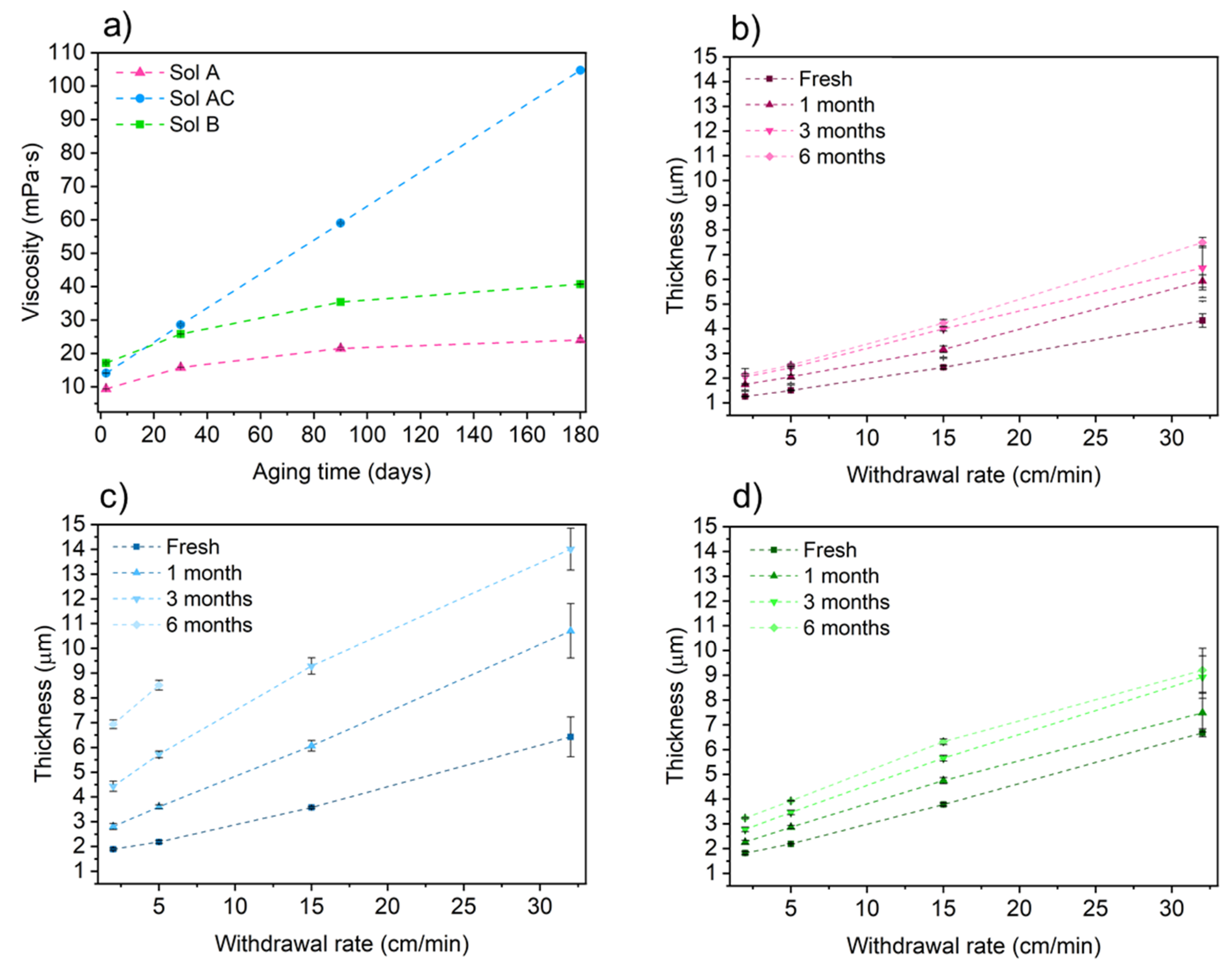
3.1. Effect of Solid Content and Organic/Inorganic Ratio in Viscosity and Thickness

Both the viscosity of the sol and the withdrawal rate have a direct influence on dragging force during the withdrawal step of a specimen from a sol and they are highly important parameters for determining the thickness of a coating deposited by dip-coating method [20]. Therefore, the viscosity of the hybrid sol-gel formulations was studied with time, coupled to the thickness of the derived coatings for four withdrawal rates. Viscosity evolution measurements along 6 months of Sol A was previously studied [13], and it was shown that the presence of BPA organic precursor contributed to give stability to the sol, in comparison to sols with another or without organic precursor. In this work, the two formulations prepared to form denser coatings were studied and compared. Figure 1a shows the evolution of viscosity along 6 months of the sols A, AC and B, while thickness values of the coatings deposited with the three sols at different aging times are depicted respectively in Figure 1b–d.
Baseline Sol A exhibited the lowest viscosity value, 9.4 mPa·s, while concentrated Sol AC showed 14.1 mPa·s. Sol B with higher ratio of organic precursor, showed the highest initial value, 17.1 mPa·s.
The evolution of viscosity with time was different for each sol. As it was observed in previous work [13], the presence of BPA in the epoxy-silica-zirconia sol matrix improved viscosity stability with time, which is crucial for pot life extension. The three sols studied here presented different viscosity behaviors. With its low solid concentration, the viscosity of Sol A doubled after 3 months of aging and it stayed constant during 6 months at a value ~22 MPa·s. However, the viscosity evolution of high concentrated Sol AC increased linearly and abruptly with aging time. Although starting at lower values, it went higher than the one of Sol B after one month. After 6 months, the viscosity of Sol AC reached more than 100 MPa·s. For Sol B, with double molar ratio of GPTMS and BPA, the viscosity presented a similar and parallel behavior to Sol A, reaching ~40 MPa·s after 6 months of aging.
In the light of this outcome, the viscosity evolution of these epoxy-silica-zirconia matrixes with BPA organic precursor seemed to be dependent on the equivalent concentration but also on the organic/inorganic ratio since Sol B, highly concentrated but with double molar ratio of BPA, resulted in a more stable sol than Sol AC.
Such behavior of sol viscosities led to a broad spread of thickness values for the derived coatings as shown in Figure 1b–d in which the thickness of the coatings prepared with each sol, freshly prepared and after aging for 1, 3 and 6 months, is presented as function of the withdrawal rate. As expected, thickness of deposited coatings increased linearly with withdrawal rate since the dragging force is proportional to both viscosity of sol and withdrawal rate. This is the general behavior for these systems when located in the dragging regime of deposition that corresponds to this relatively high range of speed [21]. The thickness of the coatings prepared with fresh sols at a withdrawal rate in the range 2–35 cm/min, were in the range 1.3–4.3 µm for Sol A, 1.9–6.4 µm for Sol AC and 1.8–6.7 µm for Sol B. These values were in agreement with the relative viscosity values obtained for the corresponding sols.
The coating thickness also increased as a function of sol aging time, as a consequence of the viscosity increase. The thickest coatings were thus obtained with the concentrated Sol AC. After 6 months of aging, crack-free coatings were only obtained at lower withdrawal rates.
The thickness of the coatings prepared with Sol A and deposited on aluminum alloys were obtained from analysis of the cross-section SEM images (see Figure 2). The thickness of the coatings on AA6061 varied from ~1.5 to 3.2 µm depending on the withdrawal speed (5, 15 and 35 cm/min) and the values were consistent with those obtained for the same coatings deposited on smooth glass and measured by contact profilometer. In a similar way, the thicknesses of coatings derived from Sol A, high-concentrated Sol AC and high-organic/inorganic ratio Sol B, all deposited at 15 cm/min on AA6082, were ~2.4, ~4 and ~4.4 µm, respectively, also consistent with the values obtained on smooth glass by profilometry.
In this work, the control on coating thickness was crucial due to the relevance of this feature on corrosion protection and contact electrical resistance of coated aluminum alloys. A priori, the densest coatings with the highest thickness would permit to achieve better protection properties at the expense of a high contact electrical resistance. It is necessary to reach a tradeoff between these properties in order to fulfill the aerospace requirements.

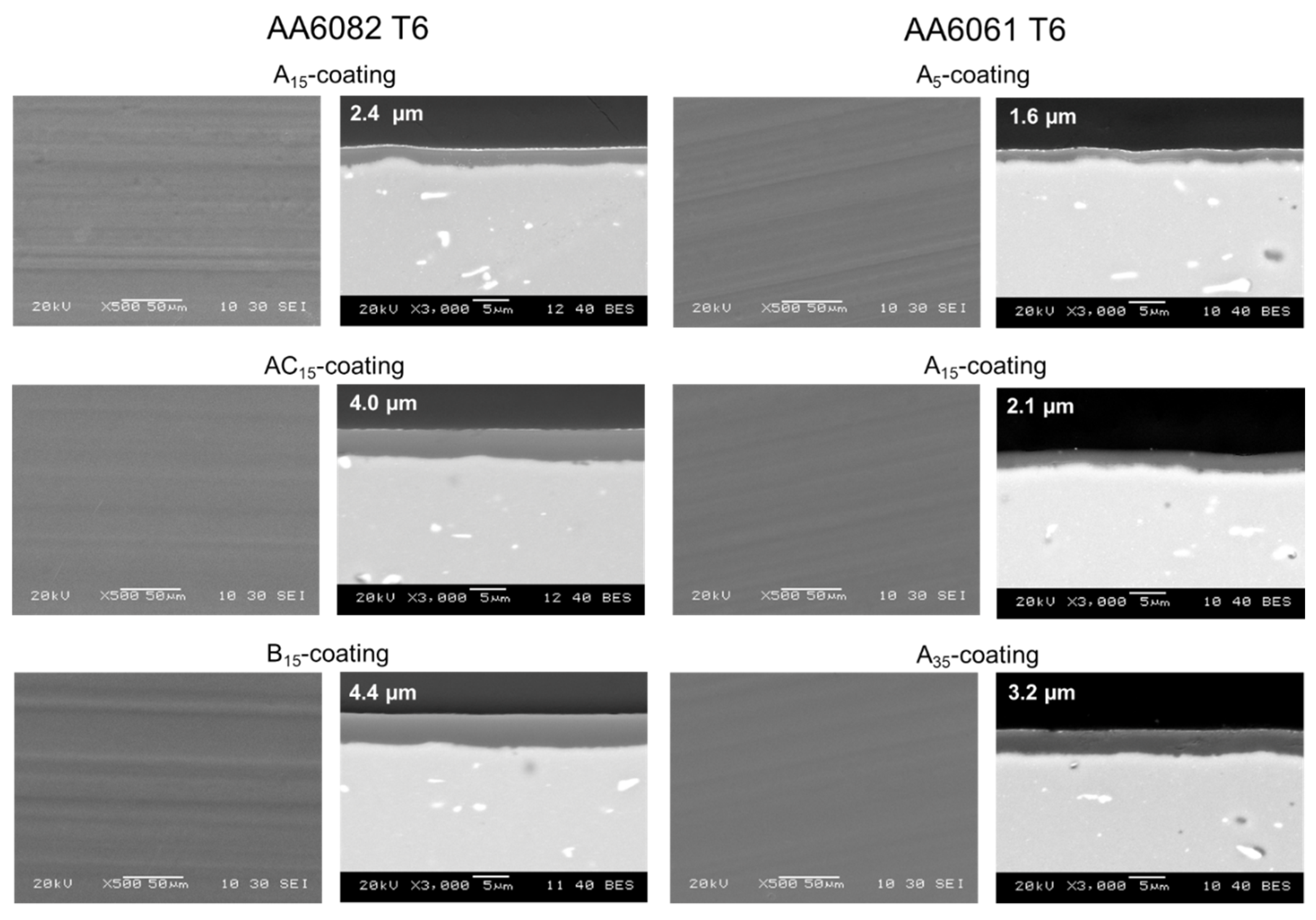
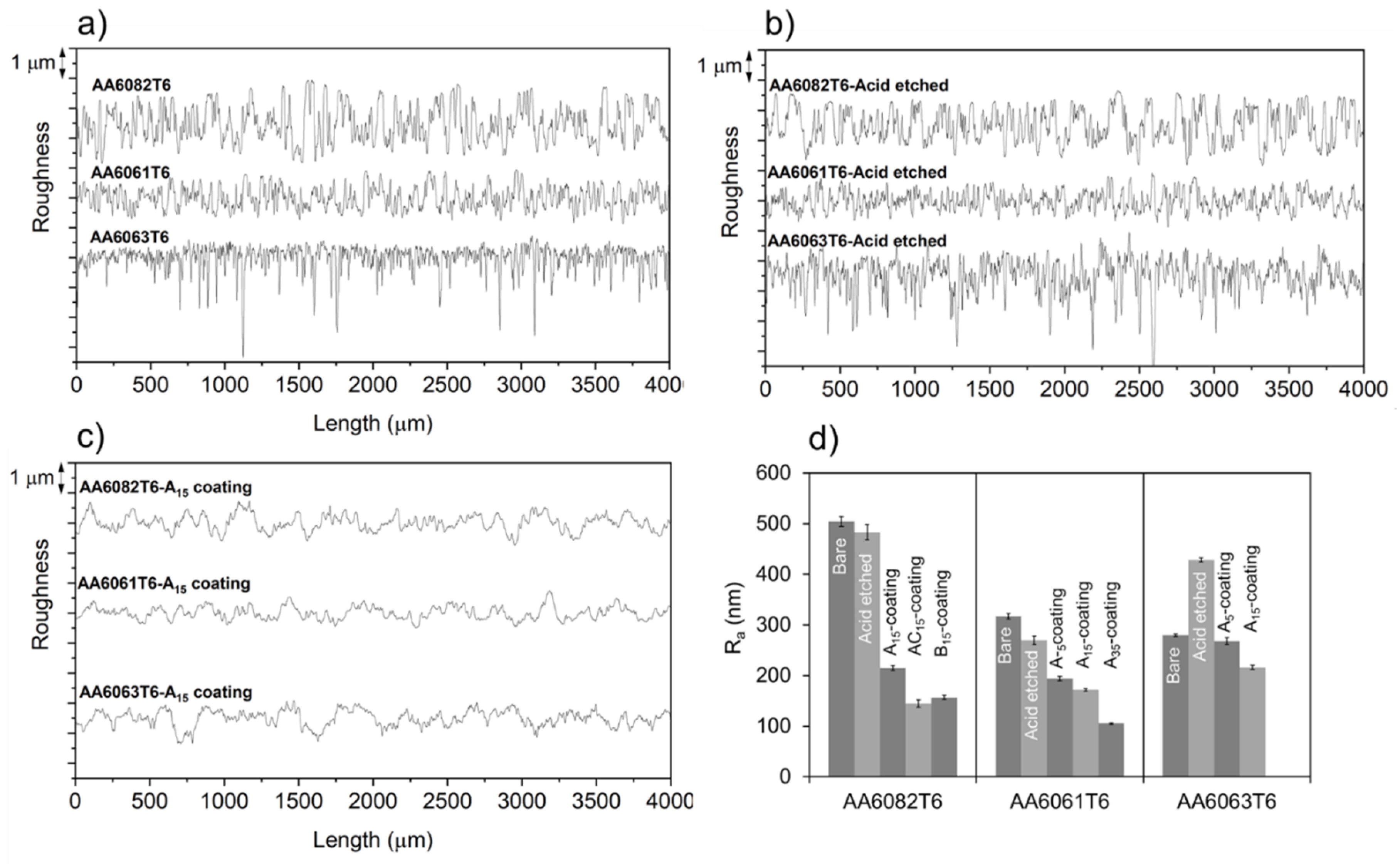
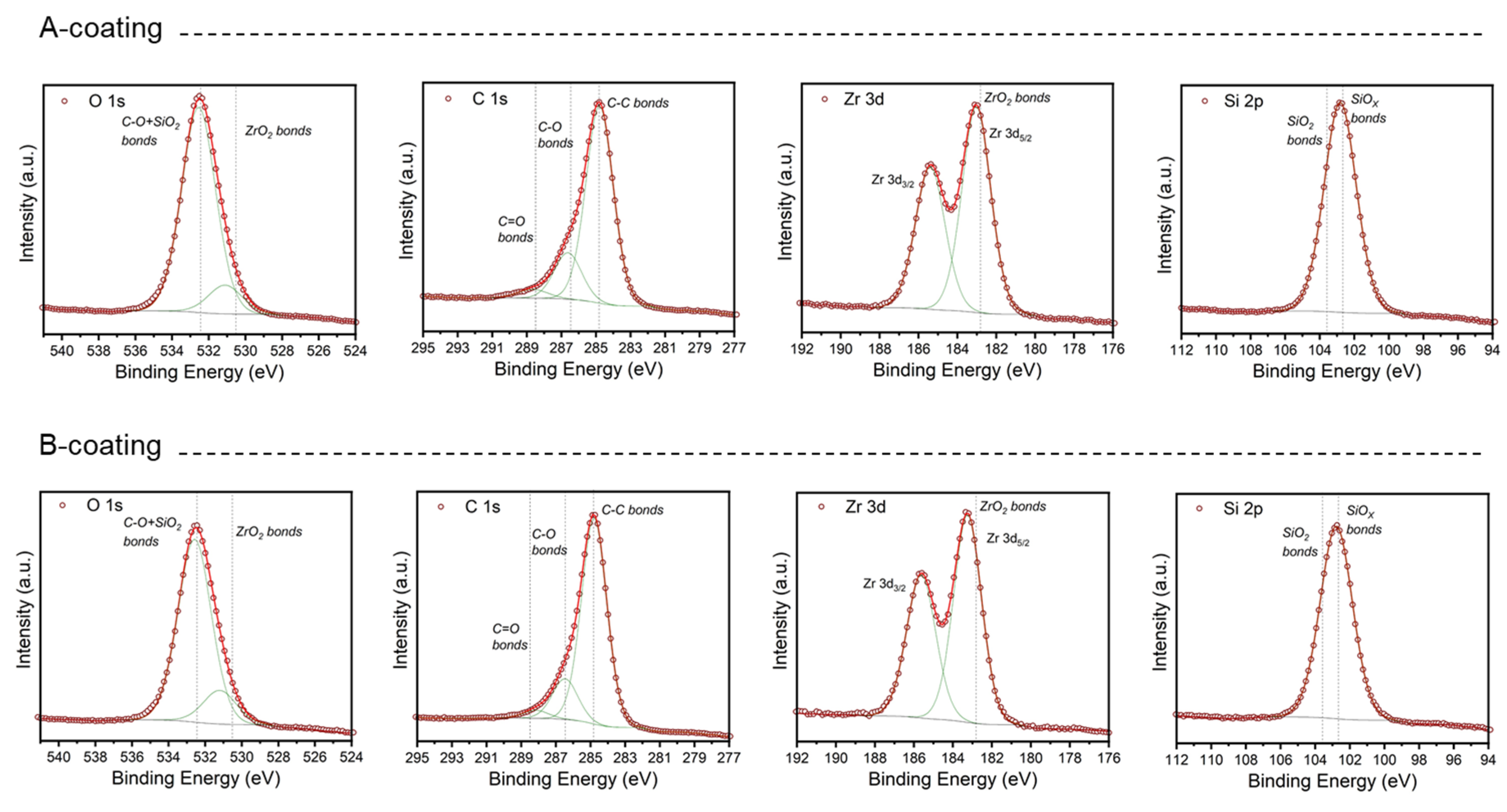
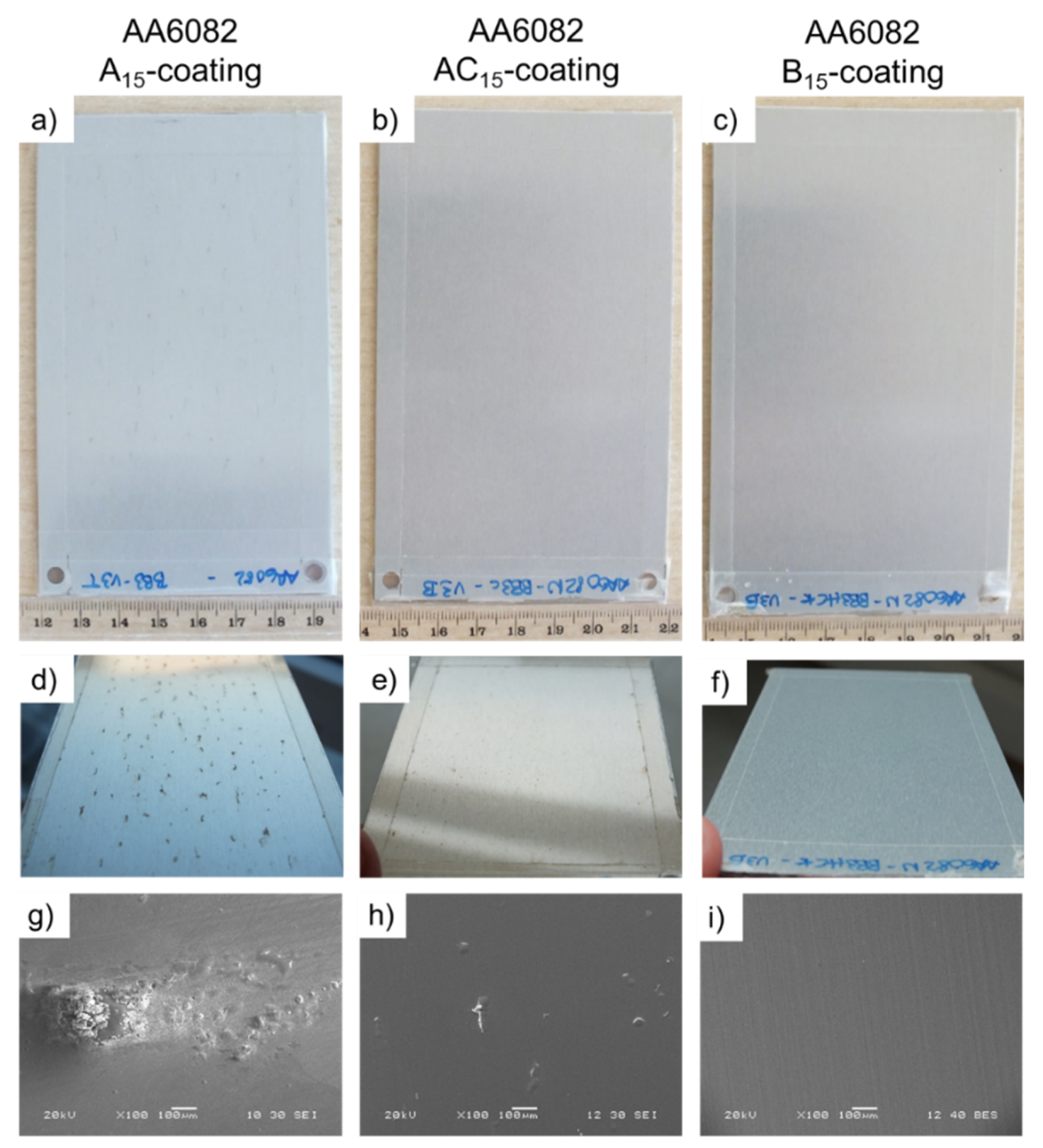
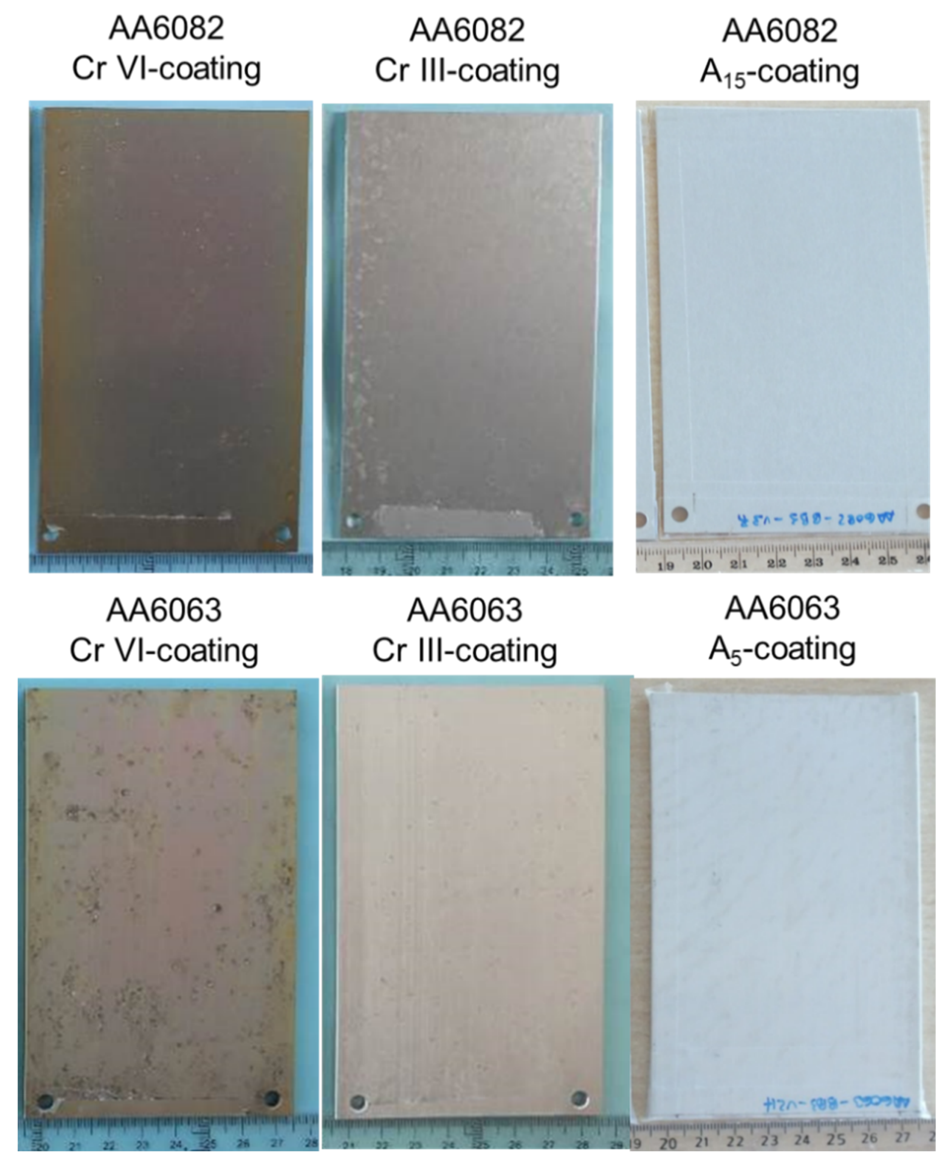
3.2. Coating Composition, Appearance and Roughness

All the sols formed highly adherent and crack-free coatings on the aluminum alloys after the thermal treatment, as observed in the top-view and cross-section images in Figure 2 and Figure 3. In the top-view analysis, the parallel lines coming from the deformation of the substrate during the cold rolling process were visible, due to the thin nature of the coating.
The roughness of uncoated, acid etched, and sol-gel coated aluminum surfaces was measured. It was observed (Figure 4) that the roughness and profile of the uncoated surfaces differed between the three aluminum substrates. AA6082 presented the highest Ra value, ~500 nm, roughness of AA6061 was Ra ~ 320 nm and AA6063 displayed Ra ~ 280 nm. However, as noticed in Figure 4a, while the profiles of AA6082 and AA6061 presented peaks and valleys of the same magnitude, Rp ~ 1400 and Rv ~ 1100 nm, AA6063 displayed deep valleys of ~3200 nm. After etching treatment, the surface roughness slightly diminished for AA6082 (Ra ~ 480 nm) and for AA6061 (Ra ~ 270 nm), composed by peaks and valleys of the same height and depth (Rp ~ 1200 and Rv ~ 900 nm). However, the etching treatment varied the profile of AA6063 as the etched surface displayed more valleys of Rv ~ 3200 nm and the average roughness Ra increased up to ~ 430 nm. The coatings deposited on such alloys contributed to level their surface (Figure 4c), thus reducing the average roughness as coating thickness increased, promoted either by increasing solid concentration and organic/inorganic ratio of sols deposited at similar rates on AA6082 or by increasing rate during withdrawal step from a given sol as observed for AA6061 and AA6063. The lowest roughness value of a coated aluminum was around 100 nm for the particular case of AA6061 coated with Sol A at 35 cm/min.
The coating composition was analyzed by XPS spectroscopy. The high-resolution XPS spectra of O 1s, C 1s, Zr 3d, and Si 2p corresponding to A- and B-coatings are presented in Figure 5. Through their analysis, it was possible to determine the accurate peak positions and associate them to ZrO2, sub-stoichiometric SiOx bonds, C–C, C–O and C = C bonds. Table 4 collects the atomic percentage of each element in the coating materials derived from sols A and B as well as semi-quantitatively estimation of the stoichiometry of the Zr and Si oxides. In both materials, the silicon oxide lacked oxygen in a major proportion than the zirconium oxide, as explained in previous recent work [13]. On the other hand, the analysis verified that Si/Zr ratio was equal to 5 in both coatings and confirmed the higher quantity of carbon in B-coating, coming from its higher organic/inorganic ratio compared to A-coating.
Ag NWs were embedded in the Sol A with the aim to decrease surface electrical resistance through the creation of a conductive path across the hybrid coating. For this purpose, Ag NW size was selected in order to provide a high aspect ratio (huge longitudinal dimension compared to diameter) and make the contact between the nanowires highly probable, thus assuring a continuous conductive path with a low concentration of NW.
The surface of the coatings was observed by SEM and two different micrographs are shown in Figure 3. The two images gave evidence that embedded NW emerged out of the coating material, which was considered favorable from the point of view of electrical contact. The difference observed between Figure 3a,b was that NW were not probably homogeneously distributed. Figure 3a showed a single NW emerging from the coating material while some NW agglomerates were also found emerging from the surface, as observed in Figure 3b.

3.3. Contact Electrical Resistance

In order to provide antistatic performance, aluminum surfaces must show low contact electrical resistance. One of the main differences between chemical conversion coatings and hybrid sol-gel coatings is the thickness. Through two distinct methods, both technologies grow dielectric coatings based on mixed metal oxides with further organic moieties in the case of sol-gel. However, the corrosion protection provided by an intentionally dense and insulating hybrid sol-gel coating material competes with the low resistivity that it should be offered. Thus, a proper balance of these properties must be envisaged to provide corrosion resistance enhancement and low surface electrical resistance. The aerospace industry usually regards MIL-DTL-81706B standard [15], which details the requirements of the chemical conversion materials for coating aluminum alloys. In a particular case, materials that form corrosion protective coatings by chemical reaction with aluminum alloys are required for aluminum compounds that need low electrical resistance. The contact electrical resistance measurement consists of evaluating the bulk resistivity of a coated aluminum plate 1-mm thick, placed between two polished copper electrodes under a contact pressure of 200 pounds per square inch. Therefore, such method is not focused on measuring the electrical resistance of the coating itself, but that of the coating-material system under pressure. In this system, several factors related to coating-electrode and coating-material interfaces such as coating thickness, coating density, substrate roughness and coating roughness may have a crucial role in the measurement.
As explained, the AlMgSi alloys present different amounts of Mg, Si and Cu alloying elements, which results in differences in the susceptibility to corrosion of each alloy. In this work different options have been explored for each alloy in order to obtain the proper tradeoff between corrosion resistance enhancement and low surface electrical resistance. For the protection of AA6082, which contains a high quantity of Si and is the most susceptible to corrosion, thick and dense coating materials were envisaged. Sol A deposited at 5 and 15 cm/min was studied, and two different strategies to prepare denser materials by increasing solid concentration and organic/inorganic ratio were accomplished, thus sols AC and B deposited at 5 and 15 cm/min. For AA6061, which contains high quantity of Cu and is usually envisaged for electrical and electronic aerospace applications where low contact electrical resistance is required, different thicknesses of the less dense A-coating were studied. Sol A was deposited at 5, 15 and 35 cm/min to achieve the tradeoff between corrosion protection and electrical resistance. With the aim to create a conductive path, Ag nanowires were loaded in a low concentration in the A sol-gel matrix and the resulting coatings were studied on the AA6063 alloy.
According to MIL-DTL-81706B standard [15], before exposing plates to NSST, the average of contact electrical resistance measurements shall be not greater than 5000 µΩ per square inch, while individual measurements shall not exceed 6000 µΩ per square inch. Based on that, mean and individual values of contact electrical resistance for the three alloys are presented in Figure 6. It was not possible to measure the resistance of AC15- and B15-coatings on AA6082 because of the insulating nature of the coatings, resulting in open circuit. None of the coatings deposited on AA6082 (with a thickness between 1.6 and 4.4 µm as shown in Figure 1 and Figure 2) exhibited electrical resistance mean values below 5000 µΩ per square inch. However, the coatings deposited with Sol A on AA6061 (with a thickness between 1.6 and 3.2 µm, as shown in Figure 1 and Figure 2) presented mean values below 5000 µΩ per square inch, although one individual value exceeded 6000 µΩ per square inch for the thicker coating system. A remarkable result was that A5- and A15-coatings provided low contact electrical resistance only if deposited on AA6061 instead of AA6082. In the same direction, A5-coating on AA6063 did not provide mean values below 5000 µΩ per square inch. The electrical resistivity of these aluminum alloys can vary from 3 to 4 × 10⁻⁶ Ω·cm [14], while the coating material has high electrical resistivity due to its hybrid organo-ceramic nature. Therefore, it is considered that the contact electrical resistance is the result of the measurement method, electrode-coating-metal interfaces and the alloy. It is expected that electrons are likely to find a path when a high pressure is applied on the thinner and less dense coatings. If such coatings, with highly levelling effect, are applied on rough metal surfaces, the path between metal peaks and the electrode is even reduced. In particular, the surface of AA6063 did not present peaks, which can stand as the main reason to not meet contact electrical resistance criteria even with such thin coatings. As AA6063 presents low susceptibility to corrosion with neither Cu content nor Si excess, Ag NW were embedded in the A-coating with good electrical results (Figure 6c). However, a tradeoff with corrosion resistance should be performed (see corrosion results).
According to MIL-DTL-81706B standard [15], contact electrical resistance should be measured again after 168 h of exposure to NSST. In this case, the average of contact electrical resistance measurements shall be not greater than 10,000 µΩ per square inch, while individual measurements shall not exceed 12,000 µΩ per square inch. Contact electrical resistance after NSST exposure was measured only on A-coating deposited on the three alloys (Figure 6d). It can be observed that the contact electrical resistance on AA6061 and AA6063 met all the standard’s criteria. However, coated AA6082 after exposure did not exhibit an average value below 10,000 µΩ per square inch.

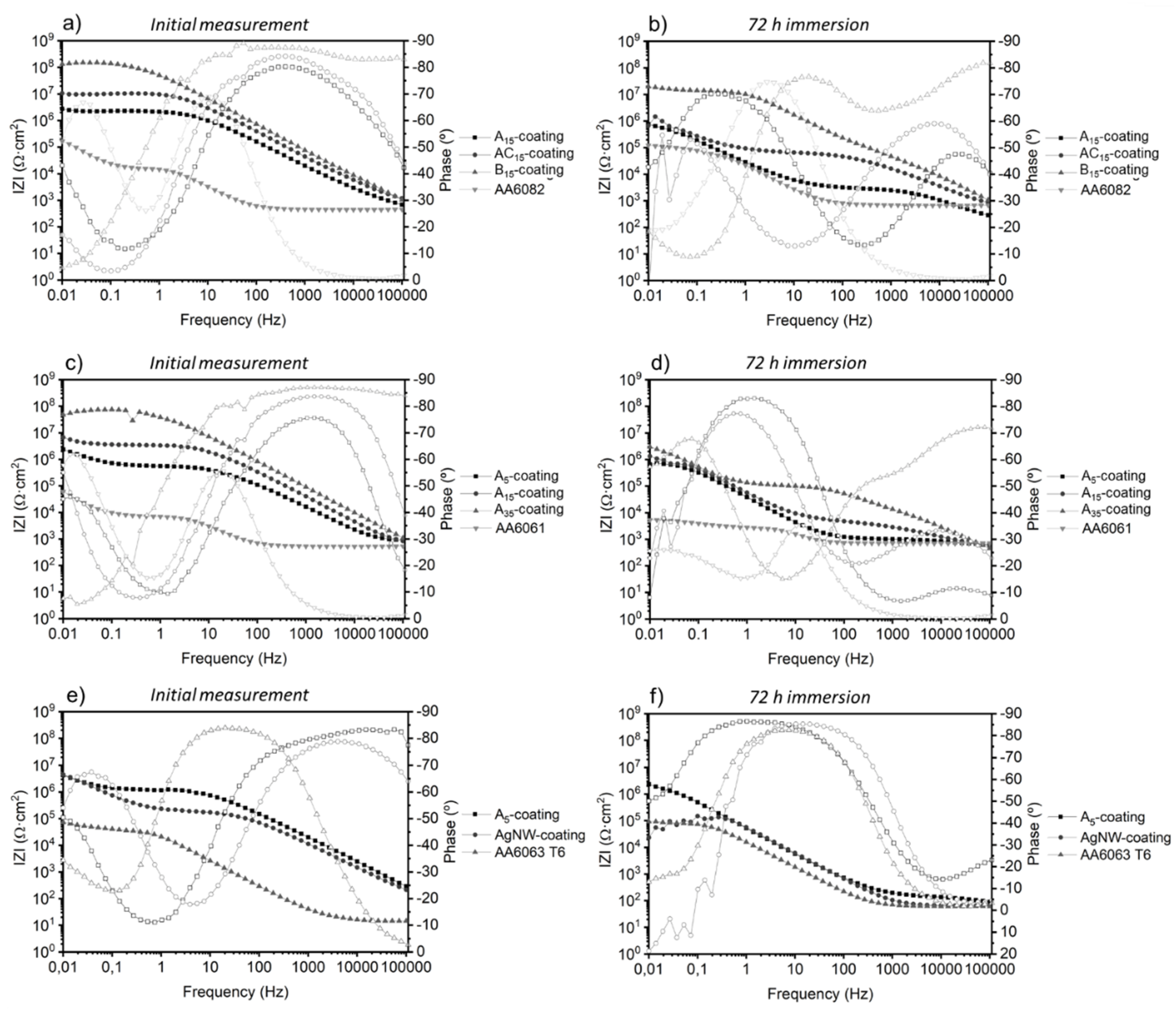
3.4. Electrochemical Characterization

Impedance measurements were recorded during immersion in 3.5% NaCl solution at 0, 2, 5, 24, 48 and 72 h. Bode frequency plots corresponding to coated and uncoated AlMgSi alloys at initial and final times of immersion are depicted in Figure 7. Based on the high repeatability of the measurements, the plots corresponding to only one repetition are presented. AA6082, with a high 1% wt Si in their composition, has the highest susceptibility to corrosion. High concentrated sols AC and B, the latter with high organic/inorganic ratio, were deposited at 15 cm/min and studied in parallel with Sol A for comparison. AA6061 is the alloy with a better tradeoff between corrosion susceptibility, mechanical and electrical properties. This alloy was coated with low concentrated Sol A at 5, 15 and 35 cm/min with the aim to study the coating thickness effect on barrier properties. AA6063 presents low corrosion susceptibility, and it was coated with Sol A at 5 cm/min. Effect of Ag NW incorporation in Sol A was studied on this alloy as it provided the required conductive electrical path to reach the requested low contact electrical resistance.
Differences between the coatings applied on AA6082 were found from the initial stages. The impedance of all the coated AA6082 substrates presented a parallel combination of the coating capacitance, over a wide frequency range, and the pore resistance. The impedance modulus at low frequencies reached ~2 × 10⁶, ~1 × 10⁷ and ~1 × 10⁸ ohm·cm2 for A15-, AC15- and B15-coatings, respectively. The boundary where the capacitive region transforms in a resistive region at phase angle about 45° is known as breakpoint at low frequency and it can be used to evaluate and rank the performance of coatings [22]. It is related with the defect area, which is lower as breakpoint emerges at lower frequencies. In particular, it was found around 7 Hz for A15-coating, around 4 Hz for AC15-coating and around 0.4 Hz for B15-coating. The highest capacitance, which is related with a low dielectric constant, was observed for B15-coating, indicating a higher barrier effect against water uptake.
The capacitive behavior of all coatings dropped with time evolution, although at different rates, related to the incorporation of polar molecules, which increases the dielectric constant of the coatings. In fact, B15-coating maintained the breakpoint at 1 Hz while A15- and AC15-coatings presented new capacitance and resistance behavior associated to defect-containing coatings. Therefore B15-coating showed a capacitive behavior stable with time and therefore a low water uptake, related to the high density of the coating.
The alloy AA6061 was treated only with Sol A deposited at different withdrawal rates, resulting in coatings of the same material but different coating thickness. The impedance modulus at low frequencies reached ~2 × 10⁶, ~6 × 10⁶ and ~4 × 10⁷ ohm·cm2 for A5-, A15- and A35-coatings, respectively. The curves revealed a parallel combination of the coating capacitance over a wide frequency range, and the pore resistance. The capacitive behavior of the thicker A35-coating was highly noticeable showing a phase angle of −90° from high frequencies up to the breakpoint at 1 Hz, whereas breakpoint appeared at higher frequencies, 20 and 10 Hz for A5-coating and A15-coating, respectively.
In this case, the capacitive behavior dropped with time at a similar rate for all the coatings since they all had identic dielectric constant. Although the thicker A35-coating had shown a high capacitive performance, the water absorbed by this material made not possible to maintain the barrier effect in contrast to B15-coating applied on AA6082.
A similar behavior was found for the thin A5-coating deposited on AA6063. However, because of the low corrosion susceptibility of these Mg-Si balanced alloys, the lower concentrated sol deposited with the lower thickness was enough to provide protection since the appearance of exposed area after test did not presented corrosion products.
Concerning AgNW-coating on AA6063, the EIS results were not conclusive, since a high scattering of data was found, accompanied by the emergence of pits and corroded areas. Although works with the incorporation of this kind of material have not been found, several studies have used conductive polymers based coatings to obtain antistatic coatings on AlMgSi alloys, such as polyaniline and polypyrrole on AA6061 [23,24] and pyrrole-based silane coatings on AA6082 [25,26]. In a similar way, Martins et al. [23,24] concluded that the coated AA6061 presented in all cases lower corrosion resistance than the bare metal, and pitting corrosion.
Therefore, it is concluded that in this kind of hybrid coatings, the incorporation of a conductive path along an insulating coating is not compatible with the corrosion protection, even on Al alloys with low susceptibility to corrosion.

3.5. Durability Assessment

Different aging tests were performed to assess the corrosion performance of the three AlMgSi alloys under study. NSST according to MIL-DTL-81706B [15] is commonly regarded by the aerospace industry as the most aggressive corrosion test for qualification of materials. Neutral salt spray exposure after thermal cycling was used in this work to assess the coated aluminum alloys ability to withstand induced thermal stress. The damp heat exposure test, with milder conditions, is also required by the space industry.
Representative photographs and SEM images of AA6082 plates coated with sols A, AC and B at 15 cm/min after 168 h of exposure in NSST are shown in Figure 8. Although not visible in front-view images of the tested surfaces (Figure 8a–c), AA6082 coated with Sol A displayed pits along the surface (Figure 8d), starting as black grains along the substrate rolling direction. Corrosion products drained from those pits were present, as observed in the SEM image in Figure 8g. The AC15-coating, with higher thickness, provided good corrosion protection as observed in Figure 8b,e, where no damage on the surface was observed. Only some defects attributed to coating damage were observed in SEM analysis as presented in Figure 8h. On the other hand, the best corrosion performance and appearance after test was displayed by the B15-coating. The higher organic/inorganic ratio in the composition allowed to avoid any crack failure provoked by stress during the test.
Concerning AA6061 and AA6063, with lower corrosion susceptibility, the thinnest A5-coating provided enough protection after 168 h of NSST, as requested in MIL-DTL-81706B standard [15] (Figure 9a,b). However, as predicted by EIS measurements, the AgNW-coating did not provide corrosion protection for AA6063. This corroborates further that the conductive path created by the Ag nanowires is incompatible with the anticorrosion property provided by a hybrid coating whose protective strategy is based on metal insulation from aggressive environment.
Cr VI and Cr III conversion coatings on AA6063 and AA6082 were also tested for comparison, as they are still currently used for aerospace applications. These coatings provided corrosion protection for the studied alloys after 168 h in NSST. However, different protection behavior was observed after thermal cycling tests (Figure 10). The expansion and contraction of the samples as they are heated up and cooled down did not cause fatigue or adhesion failure of the coatings due to thermal shock. However, corrosion protection performance was altered. AA6082 coated with Cr VI and Cr III conversion coatings presented corrosion products after 24 h of exposure in NSST following thermal cycling, in contrast to A15-coating which provided corrosion protection and a homogeneous surface as observed in the photographs showed in Figure 10. In the same way, Cr VI and Cr III conversion coatings did not displayed proper corrosion protection on AA6063 after 168 h of NSST following thermal cycling, in contrast to A5-coating, which provided unaffected aluminum surface after this time of exposure.
Considering exposure to milder conditions (DHT), none of the AA6082 and AA6063 plates coated with Sol A, and conversion coatings based on Cr VI and Cr III showed any surface failure after damp heat exposure during 336 h, as observed in Figure 11.

3.6. Vacuum-Induced Outgassing

Assessment of outgassing of the coatings derived from the three proposed sol formulations was performed to check the suitability for space applications. The sublimation test described in ECSS-Q-ST-70-02C [16] served to quantify the mass loss of coatings due to vacuum conditioning at elevated temperature as a function of time. As explained above, the coatings undergo a 24-h pre-conditioning step at 22 °C and 55% RH, during which they absorb moisture. Then, the vacuum thermal test is performed during 24 h at 125 °C and < 10−4 Pa. The difference in weight of the coating before and after this step corresponds to the total mass loss (TML) parameter. During this time, condensed matter is collected in cooled plates. The mass gain of collectors relative to initial coating mass is designated as collected volatile condensable material (CVCM). After a post-conditioning step of 24 h at 22 °C and 55% RH, during which the coatings are allowed to recover the absorbed moisture, they are weighed again, to calculate moisture uptake, designated as water vapor regained (WVR). Then, recovered mass loss (RML) is the difference between TML and WVR and corresponds to the total mass loss of the specimen itself without the absorbed water.
As observed in Table 5, the TML of coatings was between 3.5% and 5.5% depending on the coating formulation. The lowest value corresponded to the coating with the highest organic content, thus B15-coating. However, this value was highly influenced by the moisture uptake, which indeed was related to the density of each coating. In addition, the organic/inorganic ratio played a crucial role in the density of the coating, more than equivalent solid concentration, as concluded in the EIS analysis. The B15-coating with highest density, absorbed 1.76% of moisture. The AC15-coating with the lowest density, absorbed 4.165% of moisture. Consistently, A15-coating with slightly higher value of density, absorbed less quantity of moisture, 3.753%. Meanwhile the difference between Sol A and Sol AC is the equivalent solid concentration, the coatings derived from those sols at similar withdrawal rate differ on the thickness, being 2.4 and 4 µm when deposited at 15 cm/min, respectively. This affected the coating densification during the curing step. However, the lower propanol quantity lead to attain a lower inherent mass loss with an RML of 1.318%. On the contrary, B15-coating, which showed the lowest moisture uptake, presented the highest intrinsic mass loss induced by vacuum, RML reaching 1.791%, as well as extremely high quantity of volatile material condensed on cool collector. In fact, CVCM reached up to 0.3%, in contrast to the low values registered from A15- and AC15-coatings, being <0.01%. The condensed material from B15-coating was mainly bisphenol A according to FTIR analysis.
The outgassing requirements described in ECSS-Q-ST-70-02C standard [16] are RML < 1.0% and CVCM < 0.10%. Meanwhile, materials with RML < 1.0% and TML > 1.0% are considered acceptable should they meet several conditions mentioned in the standard. Therefore, only A15- and AC15-coatings fulfil the CVCM < 0.10% requirement, while RML should be slightly reduced since WVR only affects only to some specific applications. As an example, longer thermal treatment would promote further desorption and release of unreacted species entrapped or weakly bonded to coating network, which are prone to abandon it in vacuum conditions.

4. Conclusions

The suitability of hybrid sol-gel coatings applied on three different AlMgSi alloys for aerospace application was assessed. Sol-gel formulations were based on the combination of inorganic precursor of silica (TEOS) and zirconia (TPOZ) and organic precursor (BPA) interconnected to the matrix through Si epoxy functionalized-alkoxide (GPTMS). The effect of equivalent solid content, organic/inorganic ratio and withdrawal rates during coating deposition was assessed. These parameters have a crucial influence on sol viscosity, coating thickness and roughness, which were found to be directly related to contact electrical resistance, corrosion protection, barrier effect, water uptake, durability and outgassing properties.
Among the assessed AlMgSi alloys, AA6063, with balanced amounts of Mg and Si, presents the lowest mechanical properties and the lowest susceptibility to corrosion. The thin A5-coating deposited from the low concentrated Sol A was enough to protect it against corrosion in neutral salt spray test, thermal shock during thermal cycling and damp heat exposure, in spite of the tendency to water uptake revealed by the results of both EIS performed in immersion in sodium chloride solution and outgassing test (post-conditioning step). Because of the particular topography of its surface, the contact electrical resistance of the coated AA6063 did not meet the criteria requested by aerospace standards. A low load of Ag NW in the coating was enough to provide a conductive path and attain low contact electrical resistance, however this incorporation had a negative effect on the corrosion protection properties.
AA6061, with balanced amounts of Mg and Si, presented intermediate mechanical properties thanks to the Cu alloying element. In a similar way to AA6063, the thin A5-coating provided the required corrosion protection, as well as low contact electrical resistance before and after exposure to NSST, with better results in terms of recovered mass loss obtained in the outgassing test, that should be slightly further optimized.
In the case of unbalanced AA6082, the excess of Si confers the highest mechanical properties among the studied alloys, accompanied by a higher susceptibility to corrosion resistance. Two different strategies were followed to obtain thicker and denser coatings. The Sol B with higher organic/inorganic ratio provided outstanding corrosion protection to this alloy, showing a long stability along time. However, this higher organic content drove to the worst results under vacuum-induced outgassing. Furthermore, high contact electrical resistance values were obtained for all the tested coatings deposited on this alloy.
In the light of these outcomes, the most complete solution was found for AA6061, which showed the better tradeoff between corrosion susceptibility, mechanical and electrical properties.

5. Patents

Inventors: Cecilia Agustín Sáenz, Patricia Santa Coloma Mozo, Eider Martín Ugarte, Marta Brizuela Parra; Applicant: Tecnalia. A hybrid sol-gel corrosion-resistant coating composition. WO2018073186 A1 (26 April 2018).

Author Contributions

C.A.-S.: Conceptualization, Investigation, Visualization, Methodology, Analysis and Writing—Original draft; P.S.C.: Conceptualization, Investigation and Methodology of ageing tests and electrical properties measurement; F.J.F.-C.: Conceptualization and Methodology of electrical properties measurement; F.B.: Conceptualization of outgassing test and Writing—Reviewing and editing; M.B.: Funding acquisition and Project administration. All authors have read and agreed to the published version of the manuscript.

Funding

This work has received funding from the European Union’s Horizon 2020 Research and Innovation Programme within the project PEGASUS under Grant Agreement no. 640143; from the European Space Agency within ESA ITI Programme under contract number 4000124218 (IRUCOAT4SPACE project) and from the Basque Government through FRONTIERS IV project (ELKARTEK 2018, KK-2018/00108).

Acknowledgments

The authors thank the Spanish National Institute for Aerospace Technology (INTA) for outgassing measurements.

Conflicts of Interest

The authors declare no conflict of interest.

References

  1. Mondolfo, L.F. Aluminum Alloys: Structure and Properties; Butterworths & Co. Ltd.: London, UK, 1976. [Google Scholar]
  2. Larsen, M.H.; Walmsley, J.C.; Lunder, O.; Nisancioglu, K. Effect of excess silicon and small copper content on intergranular corrosion of 6000-Series aluminum alloys. J. Electrochem. Soc. 2010, 157, C61. [Google Scholar] [CrossRef]
  3. Totten, G.E.; MacKenzie, D.S. Handbook of Aluminum; Marcel Dekker Inc.: New York, NY, USA, 2003; ISBN 9780203912591. [Google Scholar]
  4. Kairy, S.K.; Alam, T.; Rometsch, P.A.; Davies, C.H.J.; Banerjee, R.; Birbilis, N. Understanding the origins of intergranular corrosion in copper-containing Al-Mg-Si alloys. Metall. Mater. Trans. A Phys. Metall. Mater. Sci. 2016, 47, 985–989. [Google Scholar] [CrossRef]
  5. Svenningsen, G.; Lein, J.E.; Bjørgum, A.; Nordlien, J.H.; Yu, Y.; Nisancioglu, K. Effect of low copper content and heat treatment on intergranular corrosion of model AlMgSi alloys. Corros. Sci. 2006, 48, 226–242. [Google Scholar] [CrossRef]
  6. He, C.; Li, R.; Meng, X.; Lü, S.; Xie, L.; Ma, G.; Wang, J. Effect of Quenching Condition on Corrosion Behavior of 6063 Al Alloy. Int. Conf. Manuf. Sci. Eng. 2015, 1873–1876. [Google Scholar]
  7. Nazeer, A.A.; Madkour, M. Potential use of smart coatings for corrosion protection of metals and alloys: A review. J. Mol. Liq. 2018, 253, 11–22. [Google Scholar] [CrossRef]
  8. Santa Coloma, P.; Izagirre, U.; Belaustegi, Y.; Jorcin, J.B.; Cano, F.J.; Lapeña, N. Chromium-free conversion coatings based on inorganic salts (Zr/Ti/Mn/Mo) for aluminum alloys used in aircraft applications. Appl. Surf. Sci. 2015, 345, 24–35. [Google Scholar] [CrossRef] [Green Version]
  9. Hoebbel, D.; Nacken, M.; Schmidt, H. A NMR study on the hydrolysis, condensation and epoxide ring-opening reaction in sols and gels of the system glycidoxypropyltrimethoxysilane-water-titaniumtetraethoxide. J. Sol-Gel Sci. Technol. 1998, 12, 169–179. [Google Scholar] [CrossRef]
  10. Yadav, R.; Tirumali, M.; Wang, X.; Naebe, M.; Kandasubramanian, B. Polymer composite for antistatic application in aerospace. Def. Technol. 2020, 16, 107–118. [Google Scholar] [CrossRef]
  11. Larsson, A. The interaction between a lightning flash and an aircraft in flight. C. R. Phys. 2002, 3, 1423–1444. [Google Scholar] [CrossRef]
  12. Gagné, M.; Therriault, D. Lightning strike protection of composites. Prog. Aerosp. Sci. 2014, 64, 1–16. [Google Scholar] [CrossRef]
  13. Agustín-Sáenz, C.; Martín-Ugarte, E.; Jorcin, J.B.; Imbuluzqueta, G.; Santa Coloma, P.; Izagirre-Etxeberria, U. Effect of organic precursor in hybrid sol-gel coatings for corrosion protection and the application on hot dip galvanised steel. J. Sol-Gel Sci. Technol. 2019, 89, 264–283. [Google Scholar] [CrossRef]
  14. Verma, S.; Gupta, M.; Misra, J.P. Friction stir welding of aerospace materials: A state of art review. In Chapter 13 in DAAAM International Scientific Book 2016; Katalinic, B., Ed.; DAAAM International: Vienna, Austria, 2016; pp. 135–150. ISBN 978-3-902734-09-9. [Google Scholar]
  15. MIL-DTL-81706B. Chemical Conversion Materials for Coating Aluminium and Aluminium Alloys; Naval Air Warfare Center Aircraft Division: Lakehurst, NJ, USA, 2006. [Google Scholar]
  16. ECSS-Q-ST-70-02C. Space Product Assurance, Thermal Vacuum Outgassing Test for the Screening of Space Materials; ECSS Secretariat ESA-ESTEC, Requirements & Standards Division: Noordwijk, The Netherlands, 2008. [Google Scholar]
  17. MIL-DTL-5541F. Chemical Conversion Coatings on Aluminum and Aluminum Alloys; Naval Air Warfare Center Aircraft Division: Lakehurst, NJ, USA, 2006. [Google Scholar]
  18. ISO 4288. Geometrical Product Specifications (GPS)—Surface Texture: Profile Method—Rules and Procedures for the Assessment of Surface Texture; International Organization for Standardization: Geneva, Switzerland, 1996. [Google Scholar]
  19. ECSS-Q-ST-70-04C. Thermal Testing for the Evaluation of Space Materials, Processes, Mechanical Parts and Assemblies; ECSS Secretariat ESA-ESTEC, Requirements & Standards Division: Noordwijk, The Netherlands, 2008. [Google Scholar]
  20. Scriven, L. Physics and applications of dip coating and spin coating. Mater. Res. Soc. Symp. Proc. 1988, 121, 717–729. [Google Scholar] [CrossRef]
  21. Faustini, M.; Louis, B.; Albouy, P.A.; Kuemmel, M.; Grosso, D. Preparation of sol-gel films by dip-coating in extreme conditions. J. Phys. Chem. C 2010, 114, 7637–7645. [Google Scholar] [CrossRef]
  22. Feng, Z.; Frankel, G.S. Evaluation of coated Al alloy using the breakpoint frequency method. Electrochim. Acta 2016, 187, 605–615. [Google Scholar] [CrossRef] [Green Version]
  23. Martins, N.C.T.; Moura e Silva, T.; Montemor, M.F.; Fernandes, J.C.S.; Ferreira, M.G.S. Electrodeposition and characterization of polypyrrole films on aluminium alloy 6061-T6. Electrochim. Acta 2008, 53, 4754–4763. [Google Scholar] [CrossRef]
  24. Martins, N.C.T.; Moura e Silva, T.; Montemor, M.F.; Fernandes, J.C.S.; Ferreira, M.G.S. Polyaniline coatings on aluminium alloy 6061-T6: Electrosynthesis and characterization. Electrochim. Acta 2010, 55, 3580–3588. [Google Scholar] [CrossRef]
  25. Trueba, M.; Trasatti, S.P. Pyrrole-based silane primer for corrosion protection of commercial Al alloys. Part I: Synthesis and spectroscopic characterization. Prog. Org. Coat. 2009, 66, 254–264. [Google Scholar] [CrossRef]
  26. Trueba, M.; Trasatti, S.P. Pyrrole-based silane primer for corrosion protection of commercial Al alloys. Part II. Corrosion performance in neutral NaCl solution. Prog. Org. Coat. 2009, 66, 265–275. [Google Scholar] [CrossRef]
Figure 1. (a) Viscosity evolution of investigated sols and (bd) thickness of coatings derived from (b) Sol A, (c) Sol AC and (d) Sol B at several withdrawal rates. (Viscosity ± 0.5 mPa·s).
Coatings 10 00441 g001
Figure 2. Top-view and cross-section SEM images of coated AA6082 T6 and AA6061 T6.
Coatings 10 00441 g002
Figure 3. (a,b) Top-view and (c) cross-section SEM images of coating deposited at 5 cm/min from Sol A loaded with 0.5% wt Ag NW, on AA6063 T6.
Coatings 10 00441 g003
Figure 4. Surface profile of (a) raw, (b) acid etched, (c) A-coated at 15 cm/min AlMgSi alloys and (d) average roughness Ra.
Coatings 10 00441 g004
Figure 5. High-resolution XPS spectra of A- and B-coating materials.
Coatings 10 00441 g005
Figure 6. Contact electrical resistance measured on three AlSiMg alloys coated with the investigated sols (ac) before and (d) after 168 h of exposure to NSST.
Coatings 10 00441 g006
Figure 7. EIS Bode modulus and phase angle plots obtained for AA6082 (a,b), AA6061 (c,d) and AA6063 (e,f) uncoated and coated with studied sols at initial time (a,c,e) and after 72 h (b,d,f) of immersion in 3.5% NaCl solution.
Coatings 10 00441 g007
Figure 8. Straight and tilted photographs and SEM images of AA6082 T6 coated with Sol A (a,d,g), Sol B (b,e,h) and Sol AC (c,f,i) at 15 cm/min after 168 h of exposure in NSST.
Coatings 10 00441 g008
Figure 9. Representative photographs of (a) AA6061 T6 coated with Sol A; AA6063 T6 coated with (b) Sol A, and (c) Sol A-AgNW at 5 cm/min after 168 h of exposure in NSST.
Coatings 10 00441 g009
Figure 10. Representative photographs of AA6082 T6 plates coated with Cr VI, Cr III and A coatings after thermal cycling and 24 h of exposure to NSST (above) and same coatings on AA6063 T6 after thermal cycling and 168 h of exposure to NSST (below).
Coatings 10 00441 g010
Figure 11. Representative photographs of AA6082 T6 (above) and AA6063 T6 (below) plates coated with Cr VI, Cr III and A coatings after 336 h of exposure to DHT.
Coatings 10 00441 g011
Table 1. Chemical nominal composition (wt%) of AlMgSi alloys.
AlMgSi AlloySiFeCuMnMgCrZnTiAl
6082 T60.900.430.090.450.900.030.090.03Balance
6061 T60.680.360.180.081.10.17<0.02<0.03Balance
6063 T60.460.23<0.050.050.52<0.050.03<0.03Balance
Table 2. Molar ratio of components used for preparing sols with and without organic precursors.
Si PartZr Part
Sol ATEOS/GPTMS/BPA/n-propanol/H2SO4 0.1M
Molar ratio 1:1:0.5:2:4
TPOZ/AcAc/n-propanol/H2SO4 0.1M
Molar ratio 1:1.4:16:3
Sol ACTEOS/GPTMS/BPA/n-propanol/H2SO4 0.1M
Molar ratio 1:1:0.5:2:4
TPOZ/AcAc/n-propanol/H2SO4 0.1M
Molar ratio 1:1.4:5.4:3
Sol BTEOS/GPTMS/BPA/n-propanol/H2SO4 0.1M
Molar ratio 1:2:1:2:6
TPOZ/AcAc/n-propanol/H2SO4 0.1M
Molar ratio 1:1.4:16:3
Table 3. Coatings deposited and studied on each AlMgSi alloy.
AlMgSi AlloySol FormulationWithdrawal Rate (cm/min)Coating
AA6082 T6Sol A5A5-coating
15A15-coating
Sol AC5AC5-coating
15AC15-coating
Sol B5B5-coating
15B15-coating
AA6061 T6Sol A5A5-coating
15A15-coating
35A35-coating
AA6063 T6Sol A5A5-coating
15A15-coating
Sol A-AgNW5AgNW-coating
Table 4. Atomic percentage of Zr, Si, C and O in the materials derived from sols A and B after Ar etching and calculated stoichiometry.
Zr (at. %)Si (at. %)C (at. %)O (at. %)Stoichiometry
A-coating3.6 118.1 145.4 132.9 1ZrO1.5SiO1.4
B-coating2.713.953.530.0ZrO1.8SiO1.2
1 Data compiled from previous work [13] for comparison.
Table 5. Outgassing parameters of coatings deposited at 15 cm/min from the sols A, AC and B.
mg/cm2g/cm3TML (%)RML (%)WVR (%)CVCM (%)
A15-coating0.541.135.157 ± 0.3921.404 ± 0.0333.753 ± 0.4550.009 ± 0.002
AC15-coating0.801.035.483 ± 0.4001.318 ± 0.1534.165 ± 0.4950.006 ± 0.003
B15-coating1.351.533.551 ± 0.0351.791 ± 0.0371.760 ± 0.0590.303 ± 0.132

