Recent Advances in Hydrophobic and Icephobic Surface Treatments of Concrete


1
Department of Civil, Environmental, Land, Building Engineering and Chemistry (DICATECh), Polytechnic University of Bari, Via E. Orabona n. 4, 70125 Bari, Italy
2
Department of Mechanics, Mathematics and Management (DMMM), Polytechnic University of Bari, Via E. Orabona n. 4, 70125 Bari, Italy
*
Author to whom correspondence should be addressed.
Coatings 2020, 10(5), 449; https://doi.org/10.3390/coatings10050449
Submission received: 11 March 2020
/
Revised: 25 April 2020
/
Accepted: 28 April 2020
/
Published: 5 May 2020
(This article belongs to the Special Issue Anti-Adhesive Surfaces)
Abstract
:In this review, we present a survey on hydrophobic surface treatments of concrete, important protection tools against deterioration and corrosion phenomena. In the frame of a standardized distinction in coatings, pore blockage, and impregnation methods, we highlight the huge variety of compounds and formulations utilized, and the different performances reached in terms of water contact angle, water absorption, chloride penetration, and, rarely reported, anti-icing/icephobic action. Our view covers the spectrum of the surface treatments, but also makes a comparison with hydrophobic bulk modifications of concrete, procedures often utilized as well; further, novel proposals of more sustainable routes are presented. We note that coating and impregnation, preferably when based on polyurethane and silane/siloxane, respectively, appear more effective against water ingress. The achieved wetting character is hydrophobic or, at most, overhydrophobic. Superhydrophobic coatings for concrete have been obtained by embedding nano-powders in hydrophobic emulsions, allowing to add a nanotexture to the preexisting complex roughness of the material. Concrete treated with this type of coating has also recently shown a pronounced icephobic character, a parameter that goes beyond the freeze–thaw characterization usually conducted on cement-based materials.
1. Introduction
With an annual production of about 10 km3/year [1], Portland cement concrete is the most used construction material on Earth, the majority of which is used in the execution of reinforced concrete structures. Nowadays, numerous concrete structures show premature degradation problems [2].
The reasons for such a low durability performance have to do with the fact that most of them were built decades ago, during a high population growth rate period, when little attention was given to durability issues; in particular, no care was given to limit permeability, an inherent property of concrete. Permeability is towards gas and liquids. Concrete is specifically highly permeable by water owing to the combination of the porous microstructure (Figure 1) and the hydrophilic nature of the concrete components, cement paste, and mineral aggregates. Penetration of water and species water conveyed cause deterioration of the concrete itself and corrosion of the reinforcements steel bars, which in turn cause functionality loss and structural risk.
The most aggressive water soluble species for reinforced concrete are chloride ions, present in marine environment and de-icing salts as they promote the pitting corrosion of steel, a fast penetrating, and hence hazardous, form of corrosion. Concrete is also affected by carbonation, which is the transformation of Ca(OH)2 in CaCO3 by reaction with ambient CO2; the occurrence of this reaction decreases the typically alkaline pH of concrete leading concrete to turn the steel surface from passive to electrochemically active. In this case, permeability to gases, such as CO2, is the key feature in concrete; however, permeability to water also has some influence in this case, as the reaction occurs in water environment.
Surface treatments of concrete are an important “additional” protection from corrosion once concrete has been correctly designed (according to the environmental exposure of the construction, classified in EN 206-1: 2005), prepared, and cured, and therefore on a concrete that, hopefully, has been provided with the lowest possible degree of permeability.
The European Standard EN 1504 [3], entitled ‘‘Products and systems for the protection and repair of concrete structures’’, includes all aspects related to the concrete protection and/or repair.
Surface treatments are presented in EN 1504-2 [4], which defines the methods for the protection of the concrete surface and classifies them as follows: (i) hydrophobic impregnation (pore liners), (ii) pore blockage (or pore sealing), and (iii) coating.
In this review, we follow this kind of classification by presenting, however, new insights from the latest research, specifically related to each method.
We note that these systems address protection from ingress, moisture control, increase of physical resistance, increase of resistance to chemicals, and increase of resistivity. However, each protection system can be effective towards one or more of these objectives; all of them act as protection from water, either with a proper hydrophobic interaction with water or by acting as a physical (passive) barrier against its entrance in the artifact.
Hence, in this review, we consider all these methods as hydrophobic treatments even when the adjective hydrophobic is not present in the definition, as it is in the case of hydrophobic impregnation (pore liners).
These contents are found in the following Section 2, with specific reference to their composition (compounds, solvents). In Section 6, all the performances related to water interaction/ingress are separately collected in order to provide a quick functional overview. In Section 3 and Section 4, bulk modifications and sustainable approaches are presented, respectively. In Section 5, we also present an overview on icephobic (and anti-icing) surface treatments and the specific meaning they take when dealing with concrete; this material, indeed, has an inherent high content of moisture (owing to the well-known phenomenon of capillary condensation), and therefore speaking of icing alone as a surface phenomenon is too restricting. Hydrophobic surface treatments have been recently tested, sometimes as icephobic and anti-icing treatments, and their performances are discussed.
1.1. Wetting Theories: The Case of Cement-Based Materials
As introductory notes to readers, the underlying theories about wetting and water absorption are briefly presented.
Wettability at static state is the result of the equilibrium of three phases (solid, liquid, and vapor) at their interfaces. A liquid droplet on the flat surface will form a contact angle, CA (θ), with the solid surface, as shown in Figure 2. The CA is determined by the surface/interface free energies (or surface tensions), which is described by the Young’s equation [5]:
where , , and are the interface tensions in the system of solid/liquid, liquid/vapor, and solid/vapor, respectively. Young’s equation is the basis to investigate the wettability of solid surfaces, and it is only appropriate for an ideally flat and homogeneous surface. In reality, the solid surface is often rough and not chemically homogeneous, and the actual or apparent CA, θ*, can be different from the Young’s CA.
The Wenzel wetting model states that a liquid can completely fill into the rough surface structures (Figure 2b), and there is a relationship between and roughness given by the Wenzel equation [6]:
where r is the roughness factor, defined as the ratio of actual solid/liquid contact area over the nominal interface contact area. Following this equation, a series of wetting phenomena can be explained. For a hydrophilic surface (θ < 90°), θ* gradually decreases with the increasing roughness, and the surface appears more hydrophilic. In contrast, the increasing roughness on a hydrophobic surface (θ > 90°) will induce a higher θ* (over–hydrophobic if higher than 120°, superhydrophobic if θ* > 150°). It is worth reporting that, very recently, it has been demonstrated that, with particularly sized textures, θ of 50–55° can be enough to result in θ* higher than 90° [7]. In any case, the Wenzel equation implies that constructing microscopic rough structures is an effective approach to enhance non-wettability, even reaching θ* of 150° or beyond. However, there are some wetting phenomena in nature that cannot be explained by this equation, such as the rolling water droplets on lotus leaf and water droplets rapidly slipping off the ladybug’s back surface [8,9].
Such wetting phenomena can be well described by the Cassie–Baxter [10] model, where the liquid (water) in contact with a rough hydrophobic material faces a composite surface consisting of both solid and air (Figure 2c). In this case, the apparent contact angle is the result of a combination of the contact angle values resulting on each interface, according to the fraction of the solid/liquid contact area with respect to the total contact area. The Cassie–Baxter equation is as follows:
where θ1 and θ2 are the Young’s CA of droplets on solid and vapor (or air), respectively; and f1 and f2 are the fractional contact of the solid/liquid and liquid/vapor interfaces, respectively. As , and Young’s CA of the droplet on air can be considered equal to 180°, the Cassie–Baxter equation can be rewritten as follows:
For a hydrophobic material with a certain value of Young’s CA, more (and/or larger) air pockets trapped by the micro or sub-microstructures of the surface will lead to a smaller , hence higher θ* and a more pronounced non wettability state.
Those interpretative models have been used to indicate two different wetting regimes for the hydrophobic materials, established depending on surface features: the “Wenzel” state characterized by the complete wetting of the surface profile (full wetting), and the “Cassie” one (also called “air pocket”, or “fakir”, or “non-wet” state) characterized by the suspension of the drop onto the surface protrusions [11].
We remind that the apparent angle considered up to now is that measured under static mode, that is, with drops still on a surface after having been gently deposited on it.
On the other hand, measuring the angle under dynamic mode consists of ‘forcing’ the probe liquid to advance over a previously non wetted portion of the surface (advancing condition), and then retracting it from the wetted surface (receding condition). Under these conditions, on real surfaces, different values are found with the advancing angle () being greater than the receding one (). The difference (), called contact angle hysteresis, is the result of the non-homogeneity of the surface and is recognized to be directly correlated to the adhesion strength between the liquid and the surface [12]. According to the Furmidge’s equation [13], indeed, the higher the hysteresis, the higher sliding angle, that is, the tilting angle of a surface plane at which a drop, previously at rest, starts to slide. According to other formulations, the adhesion strength varies uniquely depending on the receding angle, for example, with the relation , as will be seen in Section 5, where icephobicity is discussed [14].
As highlighted in recent years, the Cassie state is the one that effectively characterizes a water repellent surface. As a matter of fact, in this state, the effective energy of adhesion between the solid and water is very low, thus very low contact angle hysteresis and very low rolling and sliding friction values are found [15]. For this reason, these surfaces have been also called “slippery” superhydrophobic in contrast to the sticky ones (high adhesion, high contact angle hysteresis).
Moreover, it is understood that Cassie states may be unstable and fall in a Wenzel (full contact) regime under particular conditions (e.g., high pressure, vibrations [16,17]). Highly densely distributed sub-microstructures or hierarchical structures have been proven to be effective to ensure Cassie states with a good level of robustness [18,19].
Peculiarity of mortars, concrete, and cement composites at large is a porous structure with a broad dimensional distribution from a few nanometers to hundreds of micrometers. In Figure 1, we give at a glance an idea of the very complex texture of such materials; on the left, a real scale picture of the fracture surface with its typical macro-scale roughness including macrovoids and bubbles; in the SEM images, on the right, it is possible to appreciate the micro-scale porosity with the typical capillary pores and (bottom image) randomly distributed micro- and submicro-bump-like structures. Capillary pores are those especially involved in water transport and have a radius between 0.1 µm and 10 µm [20].
When a water solution comes into contact with a porous unsaturated material, it can be absorbed as a consequence of a depression/pressure produced by the capillary action (or interaction) between the liquid and the surface of the pores in the material.
The pressure generated in a capillary can be calculated through the Laplace–Washburn equation:
where is the mean radius of the capillary pore, is the surface tension of the liquid, and is the water contact angle.
Therefore, is higher as the pore size decreases and the water contact angle increases. In a hydrophilic material, with θ < 90°, is positive and functions as a depression that draws the water in the pore (Figure 2d); in a hydrophobic material, with θ > 90°, is negative and indicates a pressure that tends to expel the water from the pore (Figure 2e).
The former case typically occurs in cement composites, which are porous and hydrophilic materials, and water absorption easily takes place. The cementitious matrix, indeed, is made of hydrated metal and semi-metal oxides (Ca, Si, Fe) and the aggregates (65%–75% of the total volume) are normally natural siliceous or limestone sands. All of these constituents contribute to a pronounced hydrophilic character of the whole cement composite. Moreover, the typical high alkalinity of concrete contributes to its high hydrophilic character because the interaction with water also occurs in this case through acid–base reactions [21].
Using this capillary pressure in a flow velocity equation, the relation between the absorption depth (x), that is, the depth reached by the liquid, and time (t) can be derived:
where is the water viscosity and is the proporzionality constant between the absorption depth (x) and the square root of time.
From this relation, the amount of water absorbed by an area unit of the porous material (, kg/m2), as function of time, can be calculated:
where is the water density and (kg/(m2 s0.5) the capillary absorption coefficient, also called sorptivity [22], which is one of the most important and frequently determined property of a concrete and cement-based material. It is measured by standardised procedures, which basically determine, by weight, the amount of water absorbed by a properly sized specimen at known time intervals, and then derive the slope of the data linear fit. From Equations (6) and (7), it can be seen that is higher as the pore size increases.
2. Typologies of Hydrophobic Surface Treatments
Three main types of hydrophobic surface treatments can be identified: (a) coating, as a continuous film with various thickness; (b) pore blockage, as a local pore barrier; and (c) impregnation, or the so-called pore-liner, consisting of lining the pore skin all along the concrete surface [4] (Figure 3). A high number of compounds and mixtures can be found in the literature, sometimes with poor specification. In Table 1, we report a list of main compounds employed in hydrophobic surface treatments divided by treatment typology.
A common aspect of these compounds is the organic/polymeric character of their molecules. This is a cause of low surface energy, and hence low wettability [23]. Among organic compounds, those containing Si-CHx (like silanes, siloxane) or –CFx (fluorocarbons) give rise to the lowest values of surface energy. Other key features for the use as water protective products for concrete are the resistance to the alkaline concrete environment, UV, chemicals, cracking, or the possibility of being available in water and/or solvent-based versions.
The different action exerted by these methods against water (in the form of a drop) is depicted in the scheme in Figure 4. based on what was explained in the previous section: while concrete shows a hydrophilic and absorbing behavior, the coating makes a hydrophobic physical barrier, the impregnation impedes water ingress by playing a hydrophobic interaction, and the pore blockage hinders water absorption without resulting in a hydrophobic effect.
2.1. Coatings
Coatings are continuous protective layers, acting as physical barriers, which are cast on the surface of cured concrete, with thickness varying in the range of 0.1–5 mm. The binders can be organic polymers, organic polymers with cement as filler, or hydraulic cement modified with polymer dispersions. When exclusively organic coatings are utilized, the thickness is relatively lower than that of cementitious coatings, generally not exceeding 300 µm. Various kinds of polymers or resins are utilized.
The performance of two commercially available polyurethane coatings was evaluated in the study by Vipulanandan and Liu [29] under a sulfuric acid environment (typical of sewer condition) for over five years. In detail, the test results were noticeably different for the two coatings, with one extending the service life of the concrete by 14 times while the other coating did so by 57 times. Furthermore, the coated concrete specimens with pinholes were weaker than those without pinholes and the time to failure was correlated to the type of coating and pinhole size.
Almusallam et al. [28] conducted a study to evaluate the durability of concrete coated with five generic types of surface coatings: (i) acrylic coatings, (ii) polymer emulsion coatings, (iii) epoxy resin coatings, (iv) polyurethane coatings, and (v) chlorinated rubber coatings with formulation details not provided; the performance results are presented in Section 6.
Cementitious coatings are widely present in the literature. The most used organic polymers in cementitious coatings are acrylate, polyurethane, or epoxy resins (Table 1). The addition of polymers improves the cement paste’s toughness, strength, adhesion, chemical resistance, and impermeability. Other advantages of using polymer-modified cement-based coatings are related to their mitigated shrinkage and considerable breathability [40].
Diamanti et al. [26] tested the permeability of two cementitious coatings modified with acrylic polymers to water, water vapor, and chlorides. The coatings, besides reducing chloride penetration, were shown to not block the evaporation of the water vapor and, consequently, lead to an increase in the concrete durability.
The efficiency of four commercial concrete coatings (a polymer-modified cementitious mortar and three elastomeric coatings) against chloride-induced corrosion was discussed by [27], by monitoring both chloride penetration profiles and steel corrosion over the long term. To give an idea of the variety of formulations, the cementitious coating was a two-component mortar based on cementitious binders, fine-grained selected aggregates, special additives, and synthetic acrylic polymers dispersed in water with a polymer-to-cement ratio of 0.33. The elastomeric coatings were as follows: a hydro-dispersed fibrous coating, based on cement-free elastomeric acrylic emulsions; a cement-free and elastomeric acrylic-based fibrous coating mixed with graded sand; and a single-component acrylic resin-based paint in water dispersion, which forms a flexible film on the concrete surface owing to the action of natural light.
Some alternatives to conventional coatings have also been proposed. Woo et al. [25] utilized a “nanocomposite” organic-clay coating made of a mixture of isomeric octyltriethoxysilane and isooctyltriethoxysilane (generally exploited for hydrophobic impregnation of the concrete surface, below described) with two types of montmorillonite-based clay modified with different organic molecules. Accelerated weathering tests revealed that the barrier performance to various aggressive agents was not always better for this composite coating than the neat silane mixture. For instance, the average chloride content measured was reduced by 92% and 69% for neat silane and nanocomposite coatings, respectively. This is probably because of a not fully compact/dense/perfectly bond structure of this composite. It was shown that the neat silane coating permeated deeper into the concrete than the nanocomposites, indicating a better hydrophobic performance.
The coating layer can have different thicknesses and can be applied with various methods. In the study carried out by Moon et al. [30], three coatings were sprayed onto the mortar specimens: a primer as anti-deteriorating agent and two different inorganic coatings (Figure 5). Acrylic silicone mixture was applied as an outer layer and metal silicates as inner layers. The concrete with the surface treatment applied to level III exhibited the most remarkable characteristics in terms of chloride penetration and carbonation progress delay. This is reasonably the consequence of a defect decoupling occurring when multiple barrier layers are utilized.
An innovative proposal for hydrophobic concrete coatings was reported in 2013 by Flores-Vivian et al. [31], who developed emulsions composed of a surfactant (polyvinyl alcohol, PVA), a polysiloxane (polymethylhydroxysilane (PMHS)), and silica (SiO2) nanoparticles from silica fume in order to combine low energy chemistry with a nano-texture given by the silica particles. They used three different emulsion concepts (the so-called “simple”, “shell”, and “core”). The main difference lies in the use of sub-micro or nanosized particles mixed in the dispersion medium (shell scheme) or added into the siloxane drops (core scheme). The scheme of the Shell approach is reported in Figure 6, along with the SEM images of the resulting coating, where the pronounced hierarchical texture can be appreciated.
2.2. Pore Blockage
The pore blockage treatment is finalized to reduce the porosity of the surface and reinforce the concrete superficial layer; the pores are partially or totally filled with new solid/insoluble species formed upon this treatment. The compounds utilized in the treatment react only with certain soluble concrete constituents and produce the insoluble species. Many studies have shown that fluorosilicate and silicate-based solutions (e.g., lithium silicate, calcium silicate, and sodium silicate) can be considered effective in blocking capillary absorption in concrete surfaces [2]. One of the most common pore blocking surface treatment agents is sodium silicate [34]. Some experimentations have shown that sodium silicate treatment can improve the concrete durability, especially after cationic surfactant treatment (alkyl quaternary ammonium salts) [43], and hardening/densifying the surface of concrete floors [44].
Thompson et al. [45] explained three different theories on how silicates behave to improve concrete performance: (a) silicates (SiO2) precipitate in the pores, (b) silicates form an expansive gel similar to the one created in alkali–silica reactions that fills pores in the concrete by swelling, and (c) silicates react with the excess of calcium present in the near-surface region of the concrete forming relatively insoluble calcium–silicate hydrates. In this way, the pore blockers are composed of silicate and penetrate the superficial pores of the concrete, reacting with portlandite and forming C-S-H compound. In Equation (8) [45], what happens when the sodium silicate solution penetrates into the concrete pores is shown. In particular, because sodium silicate reacts with portlandite (Ca(OH)2), it is easy to understand that, in carbonated concrete, the above-mentioned reaction fails to occur. In this case, it is recommended to make an impregnation with hydroxyl ions before the sodium silicate application. Reactions of other pore blocker compounds are given in Equations (9) and (10) [2].
Na2SiO3 + yH2O + xCa(OH)2 ⟶ xCaO · SiO2 · yH2O + 2NaOH
Na2SiO4 + Ca(OH)2 + CO2 ⟶ C–S–H + Na2CO3 + H2O
MgSiF6 + Ca(OH)2 ⟶ CaF2 + MgF2 + SiO2 + H2O
It has been highlighted how the effectiveness of these treatments towards reducing water absorption is relatively poor because, essentially, they form hydrophilic compounds. On the other hand, pores are blocked also for water vapor present inside the concrete, so the risk of damage owing to freezing may increase, particularly in porous, mechanically weak concrete.
In this regard, some authors have recommended applying pore blockers when the structure is in service, when all microcracks have been produced. Moreover, when they compared a sodium silicate treatment with a silane/siloxane pore liner and two coatings (acrylic and polyurethane), it was found that the pore blocker had less satisfactory performances [33].
Some researchers have used calcium carbonate precipitation as a pore-blocking treatment on the concrete surface. It can be generated by bacterial-induced carbonate mineralization and dimethyl carbonate (DMC) solution [40]. The resistance of cementitious materials to aggressive compounds is obtained thanks to calcium carbonate crystals nucleating and precipitating on bacterial cells. Although both methods can be considered eco-friendly, they still have some drawbacks, in fact, they are very sensitive and require careful control with specific introduction practices. More details about environmentally friendly coatings will be given in Section 4.
2.3. Hydrophobic Impregnation
With the hydrophobic impregnation, the internal superficial area of the porous material is homogeneously covered with a thin lining, hence also the name of “pore liners” for these products, which exerts hydrophobic interaction with water, increasing this way the contact angle and hindering ingress of water and aggressive species water dissolved. Thus, the material will be absorption-resistant to liquid water by capillarity action (Figure 2, Figure 3 and Figure 4), but the gas/vapor permeability is hardly impeded, depending on relative humidity difference [46]. This property has the advantage to let the porous material “breathe”, so progressively decreasing its inner moisture content (Figure 7).
Silane, siloxane, and mixtures of them are the most commonly used hydrophobic impregnators. They both contain an Si-O core/backbone and alkyl and/or alkoxy groups; the general structures of silane and siloxane are presented in Figure 8; silanes, in this case, are always alkoxysilanes, and thus are sometimes also called alkyl silicates [40,48]. The silicon atom of the silane molecule is bonded to a hydrophobic alkyl group on one side and to reactive ester groups on the other side. The chemical reaction between the alkylalkoxysilane molecule and the silicate structure of the concrete requires two steps: hydrolysis and condensation. During hydrolysis, when water/moisture is provided to the silane molecules, unstable silanol molecules are formed (Figure 8d). During condensation, the unstable silanol molecules bond with the available hydroxyl groups of the silicate structure of the concrete and some crosslinking can occur by forming silicone (polysiloxane) molecules. Thus, the organic part (alkyl groups) of the silicone will orientate itself, forming a kind of a water-repellent molecular brush (depicted in the scheme of Figure 4); at the same, time the Si-O cores are covalently (or at least with H-bonds) bonded to the concrete substrate, allowing a strong anchoring to it (Figure 8d). The alkalinity of the concrete acts as a catalyst for this reaction.
These compounds are applied as water emulsion or gel-type or cream-type mixed with water. When sufficiently fluid, they are applied by spraying on the specimen surface, so they stick to the surface with the active component absorbed by capillary suction.
These treatments are transparent in their basic formulations, so they do not alter the esthetic appearance of concrete. This aspect can be clearly appreciated in Figure 9a, where pictures of the surface of a concrete specimen before and after treatment at different densities of silane are reported [49].
In general, a gel treatment is made by adding a mineral thickener to the active agent and, after the application, it can be washed or brushed away. Zhan et al. [36] analyzed capillary absorption and penetration depth of different versions of silane-based agents: liquid, cream, and gel. The cream octyltriethoxy silane (about 80%) is mixed with water in the presence of emulsifiers; instead, gel is produced by adding a mineral thickener to the active agent. In both cases, the obtained paste can be sprayed airless on the concrete surface. Tests have shown that the penetration depth of silane in concrete is strongly dependent on the concrete quality (w/c ratio), taking into account that a duration of contact of 24 h and more is necessary. The amount of silane absorbed as a function of time for all four types of concrete composition is shown in Figure 9b.
Moreover, multiple application of water repellent agents does not always lead to a significant increase in the penetration depth. The measured penetration depth obtained on concrete with water/cement (w/c) = 0.5 is shown in Figure 10. for liquid silane, cream, and gel, respectively. It can be noticed that the penetration depth does not substantially increase when the impregnated samples are treated twice. Obviously, the amount of silane per unit of internal surface will be higher, with positive effects such as a chloride barrier, for instance. Instead, in the case of cream treatment, the penetration depth considerably increases after a second and third treatment. Lastly, it should be considered that liquid silane reacts while entering the porous system; therefore, the time-dependence relation of the absorption does not follow the well-known square root of time relation [36].
In contrast to this, Dai et al. [34] found an opposite rate in the penetration depth. Their sequence of the penetration of silane-based repellent agents was as follows: silane-based gel > silane-based cream > liquid silane. According to them, a deeper penetration in the concrete could have been achieved with silane gel and cream because they have more active silane content than the liquid silane and they can remain on the surface after the application, increasing the penetration over time. The increase of penetration depth may also be a result of a decrease of the capillary size (consequence of Equation (5)) in the case of less fluid formulations.
Many studies in the literature describe various ways of application of silane-based impregnations on concrete samples [34,35,36,50].
Frattolillo et al. [37] investigated the use of siloxane and/or oligosiloxane on mortars, where the binder, the aggregate, and the water/binder weight ratio were varied, for example, yellow granular tuff, expanded clays, or siliceous sand. They report that thermal conductivity in hydrophobic mortars is always lower than in non-hydrophobic ones, proving the lower moisture content of the former ones. Even hydrophobic mortars showed higher vapor transpirability.
An innovative approach from the fabrication point of view is presented by Horgnies and Chen [24], who analyzed a superhydrophobic concrete treatment with integrated microtexture. Ultra-high performance concrete (UHPC) and ordinary concrete (OC) samples were manufactured into rectangular moulds made of (i) polyvinylchloride (PVC) or (ii) polydimethylsiloxane (PDMS). In this case, the hydrophobic agent was already present on the mould surfaces, as silicone-based (PDMS) microtexture. A solvent-based oligomeric siloxane product (Silres BS290, from Wacker-Chemie GmbH, Germany) was also deposited on UHPC and OC samples after curing. Chemical surface analyses show that siloxane-based residues were effectively transferred from the PDMS mould to the UHPC surface, thereby conferring hydrophobic properties and eliminating portlandite from the UHPC surface.
3. Comparison with Hydrophobic Bulk Modification Approaches
As an alternative to surface treatments, the addition of hydrophobic during the mixing of concrete components is frequently proposed. This procedure is known as bulk or integral water repellent treatment. In this case, the entire concrete mass acquires a certain resistance to water. Rahman and Chamberlain [51] investigated the performance given by a crystallizing aqueous and a cementitious hydrophobic mineral added to concrete components at the mixing stage at three different percentages (1%, 2%, and 8%) of the water-repellent material. The optimum performance was given by mixtures with a 2% admixture also in terms of permeability.
In some cases, compounds typically utilized as surface treatments such as silanes and siloxanes are also tested as bulk admixtures [52]. In this regard, Zhu et al. [53] found that integral silane treatment improved the durability of recycled aggregate concrete, but may lead to drops in compressive strength; instead, surface silane treatment appeared to improve the resistance to capillary water absorption, carbonation, and chloride penetration compared with integral silane treatment.
Some authors have investigated the influence of the w/c ratio on the performance of bulk silane treatments. In the study by Tittarelli and Moriconi [54], for instance, the use of silane as hydrophobic admixture prevented the corrosion of reinforced concrete even in mixtures with a w/c ratio as high as 0.80.
As an example of a variant to this approach, we mention the use of a vitrified microspheres surface modified with two hydrophobic treatments, a so-called organosilicon hydrophobic agent (OHA) and an OHA blended with cement, whose the interesting interplay between water absorption and thermal insulation under various conditions has recently been reported [55].
As an alternative to organosilicon compounds, Feng et al. [56] used as admixture in mortar mixing a waterborne stearic acid emulsion (SAE). Both superficial and inner parts turned out hydrophobic and showed a water contact angle larger than 130° (over-hydrophobic), even after being abraded, cut, and scratched. Compared with control samples, water absorption was very low and corrosion resistance to Cl− ions was much higher. However, the compressive and flexural strengths of the modified cement mortar were 16.2% and 20.0% lower than the control samples, respectively.
Instead, Wong et al. [57] considered a hydrophobically modified powder derived from waste paper sludge ash (PSA), a by-product from the manufacture of recycled paper. The results showed that absorption, sorptivity, and conductivity were reduced by 84%, 86%, and 85%, respectively, in samples with 12% hydrophobic PSA, with no negative effects on hydration, strength, and density.
Lastly, Mora et al. [58] mixed silica microparticles functionalized with organic n-dodecyl groups to concrete mortar matrices at different proportions. Even in this case, compressive strength was not affected by the modification with hydrophobic silica microparticles. The water contact angles were measured up to 122°, confirming the hydrophobic behavior of modified materials. In both of the last cases, the added material was surface modified (with hydrophobic compounds) prior to being added in the mixture.
We have recently reported, instead, a strategy that implies the utilization of secondary raw material, that is, grains from end-of-life tires, without any pre-treatment, as aggregate in total or partial replacement of natural sand. The hydrophobic properties both on the surface and in the bulk of the resulting cement composites have been proven by both the water contact angle and water absorption [59,60].
4. Sustainable Hydrophobic Treatments for Concrete
The importance of concrete durability in the context of the eco-efficiency of construction materials has been rightly highlighted by Mora et al. [58], when they stated that increasing its durability from 50 to 500 years would mean a reduction of its environmental impact by ten times. Thus, increasing the durability of concrete intrinsically means to increase its sustainability. For instance, Christodoulou et al. [38] found that silane impregnation has a residual protective effect even after 20 years of service; Vipulanandan and Liu [29] evaluated a polyurethane coating, under a sulfuric acid environment, for over five years. Creasey et al. [61] conducted a study to evaluate the effectiveness of silane/siloxane and acrylic coating repairs after 20 years since their application on façade panels of an existing concrete building. Therefore, the documented durability of the surface treatment is presumably longer than 10 years, reaching 20 years in some cases. However, in the literature, a comparative analysis about the long-term durability of different types of treatments is still missing.
Strictly regarding the treatments, many papers nowadays claim to introduce more sustainable routes for water protection of concrete artifacts. Some of those are more sustainable in terms of reduced impact of the product fabrication cycle on the environment. For example, the use of coatings based on geopolymers is considered more sustainable owing to the reduced emission of CO2 in their production. Several attempts to use geopolymers as protective coatings were found in the literature [62,63]. Geopolymer coatings have shown good resistance even in highly aggressive environments [40]. Zhang et al. [64,65] demonstrated the higher efficiency of geopolymer coatings compared with organic polymers, especially in marine environments, owing to their superior mechanical, chemical, and thermal resistance properties.
However, it should be pointed out that, while it is straightforward that the geopolymer production process leads to lower CO2 emission than that of Portland cement, it is not so clearly the same in comparison with organic and organosilicon compounds generally used as a protective hydrophobic coating. Life cycle assessments are needed to clarify this point.
From a global point of view, reduction of CO2 emission can also be pursued using waste material rather than newly fabricated ones, such as the hydrophobic powder derived from waste paper sludge ash (PSA), a by-product of the manufacture of recycled paper [57], and the rubber grains from end-of-life tyres [59,60].
Furthermore, organic coatings may have some degrees of toxicity [1]. Regulation (EU) 305/2011 related to construction products highlights the need to reduce hazardous substances. New low toxicity materials and techniques that increase concrete durability are thus needed. The most common surface treatments use organic polymers (epoxy, siloxane, acrylics, polyurethanes, and fluorocarbons in some cases), all of which have some degrees of toxicity. Polyurethane is obtained from the isocyanates and their production also involves the production of toxic substances such as phenol and chlorofluorocarbons. A general concern on the long-term effects of siloxanes on animals has been expressed by several researchers, although no acute toxic effect of ambient siloxanes on humans is known [66], or it is to a very limited extent and only in the case of cyclic compounds [67,68,69,70]. However, we remind that siloxanes are generally the final product that is applied on the cement artifact; very often, they are the result of condensations of silanes (alkoxysilanes) (mechanism in Figure 8). Such compounds are inherently more reactive and may present acute effects such as respiratory irritations; some specific cases, such as the compound studied in [34], owing to the presence of Si-H bonds, have a high level of toxicity by inhalation. Nevertheless, we believe that, to obtain credible conclusions, further research is needed, with reference to specific siloxanes and not to the whole group. In addition, the widespread use of siloxanes in different areas of life brought their migration through air and bioaccumulation into the environmental matrices, for example, in water, sediments, and soil [71].
An innovative approach, which can be considered an example of “bio-exploitation”, is the process of carbonate precipitation by ureolytic bacteria, variously reported in the literature [72,73,74,75]. A scheme for the mechanism, as depicted by the authors, is reported in Figure 11a–c. These bacteria promote the precipitation of calcium carbonate by the production of a urease enzyme that catalyzes the hydrolysis of urea to carbon dioxide and ammonia, with an increase of pH and carbonate concentration [76]. For the biodeposition treatment, concrete specimens were immersed for 24 h (10 ± 5 mm depth) in a precultured 24 h old stock culture of Sporosarcina pasteurii. Concrete specimen subjected to biomineralization in the culture medium urea-Ca(CH3COO)2 is shown in Figure 11d,e, before and after the precipitation, respectively.
CaCO3 crystal morphology is deeply related to the type of bacterial culture and medium composition; in fact, the purer the culture utilized, the more noticeable the resistance to water absorption and the less pronounced the change in chromatic aspect [77]. Biomineralization of calcium carbonate can be also considered a green strategy to remediate cracks in concrete structures.
Though innovative and highly natural, this approach is still far from being approved as a reliable technique capable of replacing current common concrete surface treatments based on organic polymers sealers. The process is still costly and the production of ammonia in the ureolytic reaction can increase reinforcement corrosion.
Subbiah et al. [32] developed a partially eco-friendly approach. They admixed 1H,1H,2H,2H-perfluorodecyltriethoxysilane (PFDTS) with nano TiO2 and SiO2 and applied the mixture into fresh cement mortar and, after casting, as spray-coating. As an innovative green approach, TiO2 nanomaterials were synthesized using ginger (Zingiber officinale). The contact angles of normal, coated, and admixed cement mortar surfaces were equal to 45.5°, 162.3°, and 162.0°, respectively. In addition, water absorption and freeze–thawing tests were carried out, showing better performance than normal concrete mortars.
A totally eco-friendly approach, instead, can be considered the addition of water stearic acid emulsion during cement mortar components mixing; stearic acid is an organic biological molecule that is easily degradable and with hydrophobic properties arising from the long hydrocarbon chain present in the molecules [56].
5. Icephobic Concrete
Nowadays, it is understood that superhydrophobicity does not automatically lead to icephobicity, hence a specific discussion has to be conducted on this theme.
Three fundamental aspects have to be distinguished in anti-icing/icephobic surfaces, which represent a sequential lineup of defense against ice accumulation.
- Water repellence: an efficient water-repellent surface helps timely removal of the water droplet, so that ice formation can be prevented.
- Ice nucleation delay: under the circumstance that quick removal of water is difficult or impossible, a longer delay in ice formation time or a lower freezing temperature then becomes a useful feature. Often, this phenomenon is referred to as “anti-icing”.
- Ice adhesion reduction: the last defense line is to ensure a low ice-adhesion strength when ice inevitably forms to ensure its easy removal. Often, this phenomenon is specifically referred to as “icephobicity”.
5.1. Water Repellency Line
Regarding water repellency, as described above (Section 1.1), a nano/microscopically rough superhydrophobic surface is essential for the fast repellence of water droplets as the Cassie–Baxter (or air pocket or non-wet contact) state at the solid/water interface is favored by such morphologies/profiles.
It is generally accepted that ultrafine nanostructures [15] or hierarchical structures [18] are more robust against penetration of high-speed water jetting or, conversely, large protrusions/macrostructures have been proven to be highly effective in braking incoming drops and shortening the contact time [78] (Figure 12).
However, at low temperatures or under pressurized high-speed water jetting conditions, the contact mode could change to a wet contact. The same could occur if the rough surface is filled by condensed moisture. In those cases, a rough surface may be turned from an advantage to a drawback because ice adhesion on it can be even higher than on a flat surface [80].
Analogies between hydrophobic interactions in liquid and interaction involved in ice formation have been highlighted by Ramachandran et al. [81], who remarked that most surface properties needed to design a superhydrophobic surface, such as the surface roughness and free energy, to affect the icephobic performance. In this case, a hydrophobic emulsion, first developed by Flores-Vivian et al. [31] as an innovative hydrophobic coating (more detail and graphics in Section 2.1), was used to surface modify mortar tiles. It is composed of a surfactant, a siloxane (polymethylhydroxysilane (PMHS)), and silica (SiO2) nano-particles (nano-powder) from silica fume in order to combine a low energy chemistry with a nano-texture given by the silica particles. They reported WCA as high as 150° with few degrees of hysteresis and the capacity for repelling incoming water droplets influenced by the inherent macro-roughness and porosity of the mortar.
The composite and complex composition of the concrete (presence of aggregate and paste and composite morphological nature of cement) makes its surface randomly rough (and in this, connected to the bulk porosity, as shown in Figure 1). This roughness can enhance wettability when the material is left in its natural character—hydrophilic—but, on the other hand, can hinder wettability if the material character is turned to hydrophobic. In particular, the macro-roughness inherently present in concrete, once provided with a proper low surface energy chemistry, could strongly reduce the contact time of incoming water droplets [78]. In this regard, much research work could be done in the near future.
5.2. Ice Nucleation Delay Line
The ice nucleation delay is generally investigated on cooled surfaces by observing the icing time of water droplets deposited on the surface. It has been proven that, for flat surfaces, a lower surface energy leads to a decrease of the freezing temperature, provided that surface effects are maximized with respect to volume effects (i.e., the measurement is conducted by using few microliters water droplets) [82] (Figure 13).
Menini and Farzaneh [83] specifically studied the bond ice formation and judged the most icephobic chemistry the one made with –CH3 and –CF3 closely packed groups, for instance, as achievable with self-assembled monolayers.
Moreover, it has been proven that the lubricant-infused surfaces provide a higher energetic barrier for ice nucleation [80].
The presence of a texture represents a higher complexity level. Various studies focused on this specific aspect can be found on metals/alloys (electric cables, aerospace, automotive applications) [84,85], but nothing, to our knowledge, on cement composites.
On the other hand, a specific feature of cement composites that could be related to the ice nucleation delay phenomenon is the resistance to freeze and thaw (FT) cycles, often characterized in these materials, as well as with standard methods.
The porous nature and hydrophilic character of concrete, as highlighted above, make these materials intrinsically and constantly humid in their bulk, with fluctuations depending on environmental conditions (relative humidity, temperature). That is why a fundamental key performance of concrete is the resistance to FT cycles, a phenomenon involving the material in its whole volume (both surface and bulk).
The behavior of concrete during freezing and thawing depends on internal factors such as pore structure distribution of concrete and water content, as well as external factors such as rate of freezing, duration of freezing period, and freezing temperature. In general, damage to concrete due to freeze–thaw occurs because of the following factors: hydraulic pressure developing when water in the saturated pores freezes, increases its volume and a certain amount of water is forced out of the pores; the osmotic pressure caused by to the movement of water from the smaller pores to the larger pores, where ice is formed, in order to re-establish equilibrium among the concentrations of solutions in the pores; pressure appearing in concrete pores owing to salt crystallization above a critical salt concentration; different thermal contraction of the constituents; temperature gradient; chemical action of de-icing salts.
The amount of freezable water present in the capillary pores is important in determining the extent of damage to concrete during freeze–thaw cycles. The pore size distribution is considered fundamental because: (i) capillary pores can favor condensation and transport of liquid water, hence the amount of freezable water, and therefore, in the end, reduce resistance to FT; (ii) macrovoids can increase resistance by allowing pressure reduction from liquid residual liquid water upon condensation [86].
Basheer and Cleland [86] have analyzed the resistance to FT of concrete specimens at different porosity (made from different water/cement ratio) and surface treated with silane/siloxane pore liners. As reported above, while these treatments reduce the penetration of water and water-born ions, they do not prevent the passage of air and water vapor, allowing concrete to ‘‘breathe’’ and, therefore, reducing the long-term water content of concrete. These authors report of a doubled resistance to FT with respect to untreated specimens, in particular when the treatment has been made more penetrating (Figure 14).
A similar study has been accomplished more recently by Liu et al. [49], who specifically distinguished the following:
- The internal frost damage leading to bulk cracking and loss of integrity;
- The surface scaling involving progressive swelling and flaking of the mortar component.
They demonstrated that the use of silane pore liners can prevent surface scaling, but is not beneficial against internal deterioration, because this phenomenon is instead governed by moisture uptake. Hence, the progressive drying favored by pore liners is not sufficient against FT deterioration. More influential in this respect is the extent of macro air voids, and therefore the use of air voids forming additives, well known for protection against FT.
Muzenski et al. [41], instead, tested the new class of hydrophobic emulsion with nano-powder (surfactant, silane/siloxane, silica nano-particles) introduced by Flores-Vivian et al. [31], using it both as coating and bulk admixture. They reported a surface WCA near 160°. Improved resistance to FT was found only for samples with a lower water/cement ratio, hence intrinsically more subjected to deterioration. Interestingly, it is highlighted how the use of the emulsion as admixture can augment the air void system of the material, therefore exerting a double positive effect.
5.3. Adhesion Strength Line
The last defense line is the possibility of decreasing the adhesion strength between ice and the solid surface. When ice adhesion is minimized, ice eventually formed can be shed off merely owing to its own weight or natural wind action.
Ice adhesion strength is, therefore, a useful parameter because it provides an indication of how easily the formed ice can be removed from the substrate; it can be characterized by either a shear or tensile adhesion test. Currently, most researchers report ice adhesion strength in shear owing to its relatively easy sample preparation and test setup. However, as there is no standard for the ice adhesion test, each research team adopts its own testing facility. To perform the measurement, an ice column is firstly prepared on the sample surface. The shear force F to separate the ice column from the sample surface is determined to calculate the shear strength of ice adhesion,, according to = F/A, where A is the contact area of ice column with sample surface (Figure 15a).
A milestone in this regard can be considered the work by Meuler et al. [14], who have experimentally searched, onto chemically different and not textured surfaces, the best correlation between the ice adhesion strength and a wetting quantity, that is, a parameter that can be derived by a characterization of the surface/material just with liquid water. The wetting parameters compared were (advancing angle), (equilibrium angle), (contact angle hysteresis), (adimensional equilibrium work of adhesion, Young-Duprè equation), and (adimensional practical work of adhesion). The last term, contrary to the equilibrium work of adhesion, has been defined as practical because it is the actual work required to separate the liquid from the surface. The results by Meuler et al. have confirmed that is the parameter best correlated to the ice adhesion strength, with the experimental data fitted perfectly by a straight line passing through the origin. Minimal ice adhesion was found for a chemistry made with fluorodecyl polyhedral oligomeric silesquioxane (POSS). For this chemistry, near 150 KPa is measured against the 700 KPa measured on bare steel as untreated substrate (Figure 15b).
In some cases, materials with superhydrophobic nano/microtextured surface modifications have shown lower adhesion strength than the untreated material [80]. However, when a texture/roughness is present on the material surface, the ice formation mode can be crucial in determining the ice adhesion strength. Indeed, the following is observed:
- If ice is formed conforming to the Cassie–Baxter state (liquid water over to protrusions tops), the air voids act as stress concentrators that reduce the ice adhesion strength,
- If it is formed conforming to the Wenzel state (liquid water inside the cavities), the protrusions act as mechanical interlocking for ice, which is even intensified considering that expansion occurs upon solidification.
The last case causes the nano/micro rough superhydrophobic surfaces to behave worse (higher ice adhesion) than normal surfaces and even show a strength measurable on superhydrophilic surfaces (900 KPa) (Figure 15c). For this reason, when dealing with textured/rough surfaces, inferring the ice adhesion behavior directly from a wetting parameter (such as the practical work of adhesion) may be unfair.
It is worth highlighting that ultra-slippery lubricant-infused surfaces (ultra-SLIPS) have shown even lower adhesion than the best superhydrophobic surfaces, for instance, when a lubricant liquid has been used water, mimicking the interface existing between the skate blade and the ice upon skate motion [88].
Concrete and cement composites, as highlighted many times, are characterized by a rough and porous structure. Zhao et al. [42] have measured the ice adhesion strength on concrete coated with a multilayer containing fluorosilane functionalized silica nanoparticles suspended in an alcohol surfactant. The coating composition takes inspiration from the one proposed by Flores-Vivian et al. [31]; in this case the coating contains SiO2 nanoparticles grafted (covalently bonded) with closely packed –CF3 ending chains [89] and allows to obtain ice adhesion strength values as low as 50 kPa, meaning that the ice solidification occurs according to the Cassie–Baxter mode. Figure 16 shows the SEM image of the uncoated and coated concrete surface obtained by these authors; the coating clearly adds an additional level of roughness to the native roughness of concrete which may give robustness to the Cassie-Baxter state of water before and during solidification. In the same figure, performance in terms of ice adhesion strength is shown.
Muzenski et al. [41], besides the FT resistance, also investigated the potential icephobic properties of their emulsion used also as coatings on asphalt-concrete specimens. Such an emulsion is based on the same concept as that followed by Zhao et al. [42], but with different compounds (siloxane instead of fluorosilane, silica fume nanoparticles, and polyvinylalcol as surfactant). However, they just inferred icephobicity (low ice adhesion strength) from water equilibrium contact angles results (120°–140°).
The possibility of ice interlocking is particularly critical in concrete surface because, owing to the inherently fragile nature of this material, ice interlocking can give rise to the phenomenon of surface scaling, which has been justly separately investigated by Liu et al. [49] while studying the FT resistance of their concrete specimens.
Therefore, in the case of measurements of ice adhesion strength on concrete, repetitions of numerous icing-deicing cycles should be accomplished up to the detection of failure (steep increase of the adhesion strength, hence failure of the protective coating) as an indication of durability.
6. Evaluation of Performances
6.1. Water Contact Angle
The contact angle characterization is not very frequently reported in the field of cement composites, likely owing to the difficult measurement on water absorbing specimens, where the drop may not be stable on the surface for a sufficiently long time. In this regard, we point out that the information regarding the stability of the water drops upon measurements, often lacking, should be provided along with the contact angle value. Stable drops are probably those grabbed by Weisheit et al. [90] and reported in Figure 17 onto an untreated concrete tile specimen, showing a CA of about 30° (a); a siloxane surface-treated tile with a water CA of 95°; and a tile treated in the same way and weathered, as authors state, under natural conditions for five years. The decrease of the angle attests to a slight loss of performance of the treatment after such a long time.
In Figure 18, we compare the water contact angle (CA) of various hydrophobic modifications of cement composites that can be found in the literature. It is evident that the treatments proposed as icephobic are those more uniformly ensuring the highest CAs, often superhydrophobic [41,42,81,91]. Ramachandran et al. [81] measured CAs up to 151° for the specimens with polyvinyl alcohol fibers treated with silica fume containing hydrophobic emulsion. They also developed a theoretical model to correlate the droplet size with the size of irregularities on the coating surface to optimize the design of emulsions. Most of these treatments follow the method proposed by Flores-Vivian et al. [31] for obtaining a hierarchical coating using surfactants and nanopowder previously discussed. Arabzadeh et al. [92], as a rare example for cement composites, utilized polytetrafluoroethene (PTFE), measuring the highest contact angle (166°) at a spray time of 12 s and 40% PTFE content.
Anyway, coating treatments are those that more often lead to very high CAs. The original study carried out by Horgnies and Chen [24] demonstrated that both PDMS mould and siloxane-based compound spray formed a homogenous surface film. The latter method showed a high static contact angle equal to 164° and a contact angle hysteresis as low as 2.5°. However, even without this siloxane-based post-treatment, highly hydrophobic surfaces were produced directly after demoulding from a silicone-based microtextured mould. In addition, even the organic-coated cement mortar of the study by Subbiah et al. [32] reached 162.3°, much higher than the reference concrete specimen with 45.5°. As reported in Section 4, they spray-coated perfluorodecyltriethoxysilan enriched with TiO2 and SiO2 nanomaterials, synthesized using ginger (Zingiber officinale), on the concrete specimens. Interestingly they make a comparison with a bulk admixture made of similar composition, finding a CA for admixed cement mortar surface of 162°, showing the same effect of coating modification. With other bulk modification approaches, instead, a lower hydrophobic character is achieved. The CA reported on samples obtained through the bulk approach by Mora et al. [58] utilizing surface modified silica microparticles reached the value of 122°. A similar CA value was obtained by Feng et al. [56] who added stearic acid emulsion into the cement paste. According to Equation (2), as the roughness increases, the CA of the hydrophilic surface will decrease, while the CA of the hydrophobic surface will increase. In this case, the surface roughness of the treated specimens increased after being abraded and repeatedly scratched with an artistic blade. It was found that the CAs of the damaged surfaces and even the interior parts reached high values (about 148°), showing a real integral hydrophobicity.
CA values for impregnation treated concrete are hardly found in the literature, though this method is based on the generation of hydrophobic interactions between the porous surface and water. A surprisingly low value (62°) is reported in Franzoni et al. [93] for an ethylsilicate impregnated concrete, where the untreated specimen reached 30°.
6.2. Water Absorption
The measurement of water absorption is typically used in the field of cement composites and porous construction materials at large. In Figure 19, we summarize, over several works in literature, for the optimally treated specimens, the reduction in the percentage of water absorption over time normalized to the control untreated specimen. Water absorption rate (g/m2 · min0.5) is generally calculated according to Equation (7), from the classical unsaturated flow theory [22], by plotting the absorbed water per unit flow area against the square-root of time, and determining the slope of the best-fit line. When not reported by authors, we calculated the rate considering a time at which a saturation behavior is observed.
It can be noticed that, while the integral (bulk) hydrophobic treatment does not show a uniform behavior, and hence confirms the need to investigate each specific material, almost all the surface treatments of coating and impregnation reach a water absorption reduction rate higher than 90%, highlighting how effective they can be.
As for pore liners, from the study carried out by Dai et al. [34], it was clear that this treatment highly reduced the capillary water absorption of treated concrete, but without making the concrete totally impermeable. For this reason, this method is not adequate to be applied in water ponding conditions, like swimming pools and water tanks [33].
Regarding the bulk hydrophobic modifications, the super-hydrophobic powder derived from waste paper sludge ash investigated by Wong et al. [57] is very effective at reducing the amount of capillary water absorption. Partial replacement of cement with 12% super-hydrophobic PSA decreased water absorption in concrete by 83–84 relative to the control concrete. Furthermore, gaseous diffusion and permeation were not significantly affected by the super-hydrophobic treatment. Chahal et al. [74] totally reduced the water absorption of the bacteria (S. pasteurii) admixed samples, with bacteria concentration equal to 103 cells/mL and 5% of silica fume.
Surface modification of both coating and impregnation appears rather reliable in this respect. Indeed, Polder et al. [94] reached 96% reduction with a 100% silane-based coating, and 98% using a treatment with a silane dispersed in water. Christodoulou et al. [38] presented the effects of silane impregnation after 20 years from the treatment. Thirty-two concrete cores were extracted from eight full-scale reinforced concrete bridges and their water absorption by capillarity was compared with non-silane treated control cores. The results demonstrated that silanes may still provide a residual protective effect against water after a 20-year service. Specimens from control cross-beams demonstrated a reduction in their sorptivity of at least 90%.
Multiple layers coatings were investigated by Medeiros and Helene [50], with a comparison of four different types of treatments: (i) silane/siloxane dispersed in water, (ii) silane/siloxane dispersed in solvent, (iii) acrylic dispersed in solvent, and (iv) polyurethane. Their results revealed that the combination of (i) or (ii) with (iii) showed the highest capacity in terms of reduction of capillary water absorption.
The main result obtained from a comparative study carried out by Almusallam et al. [28], among several types of treatments, showed that the uncoated cement mortar specimen absorbed water at a very rapid rate and, after 56 h the total absorption, was about 5% by weight. The water absorption in the case of polymer emulsion coatings (PE) was about 3.4%, higher than for the other types of coatings. The specimens with acrylic coatings (ACs) absorbed around 0.23% of water, while those coated with chlorinated rubber (CR) absorbed about 1% of water. The polyurethane coatings reached the lowest value of weight gain (0.21%), and for the epoxy coated specimens (EP), it was 0.27% (Figure 20a). However, they noted a large dissimilarity in the performance of coatings of the same generic type (i.e., with the same principal compound), but prepared in different formulations by the manufacturers. From this study, we also highlight that the values related to weight gain correlate linearly with chloride diffusion measurements (Figure 20b) (see Section 6.3), underlining how deeply water absorption influences the ingress of chlorides.
6.3. Chloride Penetration
Chloride penetration depends on concrete properties (porosity, w/c ratio, compaction, and curing condition), on exposure condition, and on potential additional protective measures. In order to compare the efficiency of the tested integral and surface treatment to reduce chloride penetration, we analyzed the chloride concentration profiles reported by various authors, by calculating, notwithstanding the difference in measurement procedure, the reduction rate with respect to the control specimen (Figure 21).
In this case, the impregnation-based treatments show a rather uniform behavior with the chloride penetration reduction higher than 85%; dissimilar performances, instead, are recorded for different types of coatings. Bulk modifications do not give a high reduction rate in chloride penetration in general.
In the study carried out by Dai et al. [34], sodium silicate-based pore blockers were found to be inefficient in preventing chloride penetration, while the long-term efficiency of water repellent agents through impregnation was found to depend on the following: (i) type of agent; (ii) whether impregnation is carried out before or after the crack formation; and (iii) penetration depth, which should be larger than 5 mm for un-cracked concrete. The chloride penetration reduction reached the highest values with treatments with silane-based liquid, cream, and gel (93%).
Brenna et al. [27] identified the best agents in terms of efficiency against chloride-induced corrosion among a polymer-modified cementitious mortar and three elastomeric coatings, by means of steel corrosion long-term monitoring and chlorides’ penetration profiles. The cement-based coating showed the best performance on delaying chloride penetration. The percentage of chloride penetration reduction is calculated considering the Fick’s second law [95], as for the case of Diamanti et al. [26].
With a salt spray test, Woo et al. [25] considered the chloride content as an average over the depth up to 50 mm into the concrete of at least three specimens. As expected, the concrete without coating showed the highest chloride content (0.23 wt.% of concrete mass). Instead, the chloride content dropped significantly with the application of the neat silane and nanocomposite coatings, with an improvement of 92% and 69% reductions in chloride content, respectively.
The chloride penetration reduction rate calculated, instead, by Zhu et al. [53], Almusallam et al. [28], and Chahal et al. [74] is based on the total charge passed (Coulombs) through the coated and uncoated concrete specimens. It was chosen to show the best performance achieved in the study by Almusallam et al. [28] with a polyurethane coating, reaching 99% chloride reduction. Moreover, Medeiros and Helene [50] obtained the best performance in terms of chloride reducing efficiency with a polyurethane coating (86%). The main test results of resistance to chloride ion penetration in the study by Zhu et al. [53] are shown in Figure 21. The total charge passed through the coated specimen with natural aggregate was compared to the one passed through the coated recycled coarse aggregate, showing that the silane treatment was very effective, especially for recycled aggregate concrete subjected to surface water repellent treatment.
Moreover, the induced bacterial calcite deposition can lead to a reduction in chloride permeability, as found by Chahal et al. [74]. Maximum reduction in chloride ions was observed with optimum bacterial concentration (105 cells/mL) for the case with 10% silica fume concrete, which was estimated to be about 380 Coulombs.
Strictly related to chloride penetration is the influence of different hydrophobic treatments on the corrosion rate of steel reinforcement embedded in reinforced concrete (RC) prisms. Ions such as chlorides are transported into the concrete pore system by being dissolved into water, which subsequently causes a penetrating corrosion of the steel reinforcement and, ultimately, spalling of the surrounding concrete cover. Thus, it is evident that all of the above-mentioned phenomena are strongly relevant to the overall health of concrete. Different approaches to evaluate the corrosion rate of reinforced concrete are present in the literature. For instance, the steel corrosion rate can be calculated by means of linear polarization resistance measurements [27,56,96,97,98], weight loss of reinforcing steel plates [54,99], amount of corroded surface area [34,100], and opening circuit potential measurement [27,101].
Regarding potentiometric characterization, the standard ASTM C876-09 [101] reports that, if the potential is more positive than −200 mV CSE, saturated calomel electrode (Cu/CuSO4 saturated reference electrode, +318 mV SHE, standard hydrogen electrode), the probability that no reinforcing steel corrosion is occurring during the measurement is greater than 90%. Instead, corrosion activity is uncertain if the potential is in the range from −200 to −350 mV CSE and highly probable (greater than 90%) if the potential is more negative than −350 mV CSE. This criterion is not universally applicable and does not provide a straightforward steel corrosion rate. That is why various parameters are used by researchers in this respect.
Dai et al. [34] investigated the role of cracks in a marine environment on corrosion of steel bars for coated and uncoated specimens. They found that even if concrete presents cracks before surface impregnation, the internal steel bar corrosion can still be well inhibited, if deep enough penetration can be achieved. Instead, when surface impregnation was carried out before the formation of cracks, the internal steel bars showed no corrosion at all under a cover 17.5 mm deep and impregnated with a silane-based cream and gel. Lastly, an essential aspect to consider in the case of RC is represented by the depth of the concrete cover to reinforcement. These authors [34], surprisingly, found that corrosion occurred much more on steel bars covered with 45 mm of concrete and treated in the same way as the steel bars covered with 17.5 mm of concrete, when the treatment was carried after the crack formation (Figure 22). A reason may be that, because the silane-based treatment reached a mean depth of 15–25 mm, the concrete around the steel bars in the 17.5 mm cover case has no or little capillary condensed water. Conversely, the 45 mm of concrete cover around the bars could lead to higher absorption of water and gases. However, the opposite situation was reached when specimens were treated before cracking.
The published data on the long-term performance of coated RC structures still remain limited. In addition, many differences are found on sampling and testing methods, which hinder comparisons among the studies.
7. Concluding Remarks
We have presented an effort to provide a comprehensive evaluation of the field of surface treatments of concrete for protection against water ingress. In this sense, we consider such treatments, which are normally classified as coating, pore blockage, and impregnation methods, overall as hydrophobic, even when the principle is just to occlude the pores without imparting a high water contact angle (pore blockage case). We also infer to which extent surface treated concrete can show an icephobic behavior.
A high variety of chemical approaches can be found; at a glance, alkyl alkoxysilane and siloxanes are largely used both as impregnating agents (pore liners) and in coating formulations, while silicates are generally used as pore blockage products. Acrylates and polyurethanes can also frequently be found in coatings products. Fluorine-containing compounds, though noteworthy highly hydrophobic, are found less frequently in this applicative field. Besides the principal compound, specific formulations of the mixtures can be very different.
We have considered these methods also in comparison with bulk modification procedures (addition of hydrophobic agents directly at the mixing stage), which are also often tested in the literature; these kinds of methods allow to reach a certain hydrophobic character in the whole mass, and hence are more durable upon abrasion or surface deterioration, but can have the drawback of interfering negatively with the mechanical properties of the composite.
Trying to compare the performance in terms of common parameters for hydrophobic treatments, it is found that the water contact angle (CA) is rarely reported as this parameter can have poor significance if a certain water absorption occurs. Surface treatments of coating and impregnation give rise to higher CA than bulk modifications, as reasonable, because the hydrophobic agent is densely distributed on the surface where the angle is measured. However, rarely CA is higher than 140°. The highest contact angles, attesting to a superhydrophobic behavior (>160°), are found in the case of innovative formulations composed of hydrophobic emulsions with nanopowders (such as silica fume), which allows adding an additional (nano-scale) level of roughness to the pre-existing roughness hierarchy of concrete substrate. Owing to this outstanding water repellency, very recently, these formulations have been also tested as anti-icing coatings for concrete, demonstrating a reduced adhesion strength of formed ice and a repulsion of incoming droplets at a low temperature. Silane-based pore liners had been previously tested as protection under freeze–thaw conditions, as a more typical characterization for cement-based materials, demonstrating only a partially positive effect.
A typical and very often reported parameter in this field, instead, is the water absorption coefficient. The surface treatments of coating and pore liners appear, under their optimized versions, to be highly effective in impeding water ingress in the specimen’s mass. The rate of reduction with respect to control (untreated specimens) is rarely lower than 90%. Bulk procedures, instead, show sensitively lower reduction rates of water absorption.
This behavior appears to also be reflected in performances like resistance to Cl− penetration, highly relevant to corrosion of reinforcements. In this respect, impregnation with silanes and coatings based on polyurethanes appears the most successful against the ingress and diffusion of these species. In the near future, it could be interesting to test, in terms of chloride penetration, the hydrophobic emulsions with nanopowder, the coating that gave rise to the best non-wetting (superhydrophobic) performances.
When considering more sustainable approaches to water protective treatments, in terms of reduced impact of the fabrication cycle on the environment, for example, reduced emission of CO2, the use of geopolymers-based coatings has been proposed, or in a more global view, the addition of hydrophobic aggregates from recycled materials such as grains of waste tyre rubber, with the latter proven to be highly effective.
Moreover, in terms of reduced degree of toxicity towards humans and faster biodegradability of the applied products, interesting proposals appear with the addition of bacteria (biotech concrete), which promotes precipitation of carbonate acting as pore blockage, or the use of a biological organic molecule like acid stearic as a hydrophobic agent. These are both, more precisely, bulk modification approaches, and the latter appears sustainable and also more feasible.
Author Contributions
Conceptualization, R.D.M.; investigation and methodology, R.D.M., C.L. and M.N.; writing, graphics, original draft preparation, R.D.M. and C.L; supervision, manuscript revision, and resources, M.N. and G.C. All authors have read and agreed to the published version of the manuscript.
Funding
This research received no external funding.
Conflicts of Interest
The authors declare no conflict of interest.
References
- Pacheco-Torgal, F.; Labrincha, J. Biotech cementitious materials: Some aspects of an innovative approach for concrete with enhanced durability. Constr. Build. Mater. 2013, 40, 1136–1141. [Google Scholar] [CrossRef]
- Bertolini, L.; Elsener, B.; Pedeferri, P.; Redaelli, E.; Polder, R. Corrosion of Steel in Concrete; Wiley: Weinheim, Germany, 2013; Volume 392. [Google Scholar]
- British Standards Institution. BS EN 1504:2005 Products and Systems for the Protection and Repair of Concrete Structures—Definitions, Requirements, Quality Control and Evaluation of Conformity—Part 3: Structural and Non-structural Repair; BSI: London, UK, 2005. [Google Scholar]
- British Standards Institution. BS EN 1504-2, Products and Systems for the Protection and Repair of Concrete Structures—Definitions, Requirements, Quality Control and Evaluation of Conformity—Part 2: Surface Protection Systems for Concrete; BSI: London, UK, 2004. [Google Scholar]
- Young, T.R. An assay on the cohesion of fluids. Philos. Trans. Soc. R. Lond. 1805, 95, 65–87. [Google Scholar]
- Wenzel, R.N. Resistance of solid surfaces to wetting by water. Ind. Eng. Chem. 1936, 28, 988–994. [Google Scholar] [CrossRef]
- Telecka, A.; Mandsberg, N.K.; Li, T.; Ludvigsen, E.; Ndoni, S.; Di Mundo, R.; Palumbo, F.; Fiutowski, J.; Chiriaev, S.; Taboryski, R.J. Mapping the transition to superwetting state for nanotextured surfaces templated from block-copolymer self-assembly. Nanoscale 2018, 10, 20652–20663. [Google Scholar] [CrossRef] [PubMed] [Green Version]
- Orchard, M.; Kohonen, M.; Humphries, S. The influence of surface energy on the self-cleaning of insect adhesive devices. J. Exp. Biol. 2011, 215, 279–286. [Google Scholar] [CrossRef] [PubMed] [Green Version]
- Barthlott, W.; Neinhuis, C. Purity of the sacred lotus, or escape from contamination in biological surfaces. Planta 1997, 202, 1–8. [Google Scholar] [CrossRef]
- Cassie, A.B.D.; Baxter, S. Wettability of porous surfaces. Trans. Faraday Soc. 1944, 40, 546. [Google Scholar] [CrossRef]
- Quéré, D. Non-sticking drops. Rep. Prog. Phys. 2005, 68, 2495–2532. [Google Scholar] [CrossRef]
- Di Mundo, R.; Palumbo, F. Comments Regarding ‘An Essay on Contact Angle Measurements’. Plasma Process. Polym. 2010, 8, 14–18. [Google Scholar] [CrossRef]
- Furmidge, C. Studies at phase interfaces. I. The sliding of liquid drops on solid surfaces and a theory for spray retention. J. Colloid Sci. 1962, 17, 309–324. [Google Scholar] [CrossRef]
- Meuler, A.J.; Smith, J.D.; Varanasi, K.K.; Mabry, J.M.; McKinley, G.H.; Cohen, R.E. Relationships between Water Wettability and Ice Adhesion. ACS Appl. Mater. Interfaces 2010, 2, 3100–3110. [Google Scholar] [CrossRef] [PubMed]
- Di Mundo, R.; Bottiglione, F.; Carbone, G. Cassie state robustness of plasma generated randomly nano-rough surfaces. Appl. Surf. Sci. 2014, 316, 324–332. [Google Scholar] [CrossRef]
- Bormashenko, E.; Pogreb, R.; Whyman, G.; Erlich, M. Cassie−Wenzel Wetting Transition in Vibrating Drops Deposited on Rough Surfaces: Is the Dynamic Cassie−Wenzel Wetting Transition a 2D or 1D Affair? Langmuir 2007, 23, 6501–6503. [Google Scholar] [CrossRef] [PubMed]
- Bottiglione, F.; Di Mundo, R.; Soria, L.; Carbone, G. Wenzel to Cassie Transition in Superhydrophobic Randomly Rough Surfaces. Nanosci. Nanotechnol. Lett. 2015, 7, 74–78. [Google Scholar] [CrossRef]
- Di Mundo, R.; Bottiglione, F.; Palumbo, F.; Favia, P.; Carbone, G. Sphere-on-cone microstructures on Teflon surface: Repulsive behavior against impacting water droplets. Mater. Des. 2016, 92, 1052–1061. [Google Scholar] [CrossRef]
- Di Mundo, R.; Bottiglione, F.; Palumbo, F.; Notarnicola, M.; Carbone, G. Filamentary superhydrophobic Teflon surfaces: Moderate apparent contact angle but superior air-retaining properties. J. Colloid Interface Sci. 2016, 482, 175–182. Available online: https://www.sciencedirect.com/science/article/pii/S0021979716305380 (accessed on 10 January 2020). [CrossRef]
- Kumar, R.; Bhattacharjee, B. Porosity, pore size distribution and in situ strength of concrete. Cem. Concr. Res. 2003, 33, 155–164. [Google Scholar] [CrossRef]
- Favia, P.; De Vietro, N.; Di Mundo, R.; Fracassi, F.; D’Agostino, R. Tuning the Acid/Base Surface Character of Carbonaceous Materials by Means of Cold Plasma Treatments. Plasma Process. Polym. 2006, 3, 66–74. [Google Scholar] [CrossRef]
- Hall, C. Water movement in porous building materials—I. Unsaturated flow theory and its applications. Build. Environ. 1977, 12, 117–125. [Google Scholar] [CrossRef]
- Bittrich, E.; Cometa, S.; de Giglio, E.; Di Mundo, R.; Ditaranto, N.; Eichhorn, K.J.; Keller, B.; Lednický, F.; Mangolini, F.; Palumbo, F.; et al. Polymer Surface Characterization; Walter de Gruyter GmbH & Co KG: Berlin, Germany, 2014. [Google Scholar]
- Horgnies, M.; Chen, J. Superhydrophobic concrete surfaces with integrated microtexture. Cem. Concr. Compos. 2014, 52, 81–90. [Google Scholar] [CrossRef]
- Woo, R.S.C.; Zhu, H.; Chow, M.M.; Leung, C.K.; Kim, J.-K. Barrier performance of silane–clay nanocomposite coatings on concrete structure. Compos. Sci. Technol. 2008, 68, 2828–2836. [Google Scholar] [CrossRef] [Green Version]
- Diamanti, M.V.; Brenna, A.; Bolzoni, F.M.; Berra, M.; Pastore, T.; Ormellese, M. Effect of polymer modified cementitious coatings on water and chloride permeability in concrete. Constr. Build. Mater. 2013, 49, 720–728. [Google Scholar] [CrossRef]
- Brenna, A.; Bolzoni, F.M.; Beretta, S.; Ormellese, M. Long-term chloride-induced corrosion monitoring of reinforced concrete coated with commercial polymer-modified mortar and polymeric coatings. Constr. Build. Mater. 2013, 48, 734–744. [Google Scholar] [CrossRef]
- Almusallam, A.; Khan, F.; Dulaijan, S.; Al-Amoudi, O. Effectiveness of surface coatings in improving concrete durability. Cem. Concr. Compos. 2003, 25, 473–481. [Google Scholar] [CrossRef]
- Vipulanandan, C.; Liu, J. Performance of polyurethane-coated concrete in sewer environment. Cem. Concr. Res. 2005, 35, 1754–1763. [Google Scholar] [CrossRef]
- Moon, H.Y.; Shin, D.G.; Choi, D.S. Evaluation of the durability of mortar and concrete applied with inorganic coating material and surface treatment system. Constr. Build. Mater. 2007, 21, 362–369. [Google Scholar] [CrossRef]
- Flores-Vivian, I.; Hejazi, V.; Kozhukhova, M.; Nosonovsky, M.; Sobolev, K. Self-Assembling Particle-Siloxane Coatings for Superhydrophobic Concrete. ACS Appl. Mater. Interfaces 2013, 5, 13284–13294. [Google Scholar] [CrossRef]
- Karthick, S.; Park, D.-J.; Lee, Y.S.; Saraswathy, V.; Lee, H.-S.; Jang, H.-O.; Choi, H.-J. Development of water-repellent cement mortar using silane enriched with nanomaterials. Prog. Org. Coat. 2018, 125, 48–60. [Google Scholar] [CrossRef]
- Medeiros, M.H.F.; Castro-Borges, P.; Aleixo, D.M.; Quarcioni, V.A.; Marcondes, C.G.N.; Helene, P. Reducing water and chloride penetration through silicate treatments for concrete as a mean to control corrosion kinetics. Int. J. Electrochem. Sci. 2012, 7, 9668–9681. [Google Scholar]
- Dai, J.-G.; Akira, Y.; Wittmann, F.; Yokota, H.; Zhang, P. Water repellent surface impregnation for extension of service life of reinforced concrete structures in marine environments: The role of cracks. Cem. Concr. Compos. 2010, 32, 101–109. [Google Scholar] [CrossRef]
- Medeiros, M.; Helene, P. Efficacy of surface hydrophobic agents in reducing water and chloride ion penetration in concrete. Mater. Struct. 2007, 41, 59–71. [Google Scholar] [CrossRef]
- Zhan, H.; Wittmann, F.H.; Zhao, T. Chloride Barrier for Concrete in Saline Environment Established by Water Repellent Treatment/Durch Hydrophobieren hergestellte Chloridschranke für Beton in Kontakt mit Salzwasser. Restor. Build. Monum. 2003, 9, 535–550. [Google Scholar] [CrossRef]
- Frattolillo, A.; Giovinco, G.; Mascolo, M.; Vitale, A. Effects of hydrophobic treatment on thermophysical properties of lightweight mortars. Exp. Therm. Fluid Sci. 2005, 29, 733–741. [Google Scholar] [CrossRef]
- Christodoulou, C.; Goodier, C.; Austin, S.; Webb, J.; Glass, G. Long-term performance of surface impregnation of reinforced concrete structures with silane. Constr. Build. Mater. 2013, 48, 708–716. [Google Scholar] [CrossRef] [Green Version]
- Pigino, B.; Leemann, A.; Franzoni, E.; Lura, P. Ethyl silicate for surface treatment of concrete—Part II: Characteristics and performance. Cem. Concr. Compos. 2012, 34, 313–321. [Google Scholar] [CrossRef]
- Pan, X.; Shi, Z.; Shi, C.; Ling, T.-C.; Li, N. A review on concrete surface treatment Part I: Types and mechanisms. Constr. Build. Mater. 2017, 132, 578–590. [Google Scholar] [CrossRef]
- Muzenski, S.; Flores-Vivian, I.; Sobolev, K. The Development of Hydrophobic and Superhydrophobic Cementitious Composites. In Proceedings of the 4th International Conference on the Durability of Concrete Structures, Purdue University, West Lafayette, IN, USA, 24–26 July 2014. [Google Scholar]
- Zhao, Y.; Liu, Y.; Liu, Q.; Guo, W.; Yang, D.; Ge, D. Icephobicity studies of superhydrophobic coatings on concrete via spray method. Mater. Lett. 2018, 233, 263–266. [Google Scholar] [CrossRef]
- Kupwade-patil, K.; Cardenas, H.E.; Gordon, K.; Lee, L.S. Corrosion Mitigation in Reinforced Concrete Beams via Nanoparticle Treatment. ACI Mater. J. 2012, 109. [Google Scholar] [CrossRef]
- Jones, J.W.; Maxfield, P. Method of Hardening and Polishing Concrete Floors, Walls, and the Like. U.S. Patent 6,454,632, 24 September 2002. [Google Scholar]
- Thompson, J.; Silsbee, M.; Gill, P.; Scheetz, B. Characterization of silicate sealers on concrete. Cem. Concr. Res. 1997, 27, 1561–1567. [Google Scholar] [CrossRef]
- Meier, S.; Wittmann, F. Recommendations for Water Repellent Surface Impregnation of Concrete. Restor. Build. Monum. 2011, 17, 347–358. [Google Scholar] [CrossRef]
- Bertolini, L.; Elsener, B.; Pedeferri, P.; Polder, R. Corrosive Agents and Their Interaction with Materials; Wiley: Weinheim, Germany, 2004; Volume 392. [Google Scholar]
- Batis, G.; Pantazopoulou, P.; Routoulas, A. Corrosion protection investigation of reinforcement by inorganic coating in the presence of alkanolamine-based inhibitor. Cem. Concr. Compos. 2003, 25, 371–377. [Google Scholar] [CrossRef]
- Liu, Z.; Hansen, W. Effect of hydrophobic surface treatment on freeze-thaw durability of concrete. Cem. Concr. Compos. 2016, 69, 49–60. [Google Scholar] [CrossRef]
- De Medeiros, M.H.F.; Helene, P. Surface treatment of reinforced concrete in marine environment: Influence on chloride diffusion coefficient and capillary water absorption. Constr. Build. Mater. 2009, 23, 1476–1484. [Google Scholar] [CrossRef]
- Al-Kheetan, M.J.; Rahman, M.M.; Chamberlain, D. Development of hydrophobic concrete by adding dual-crystalline admixture at mixing stage. Struct. Concr. 2018, 19, 1504–1511. [Google Scholar] [CrossRef] [Green Version]
- Dong, B.; Wang, F.; Abadikhah, H.; Hao, L.Y.; Xu, X.; Khan, S.A.; Wang, G.; Agathopoulos, S. Simple Fabrication of Concrete with Remarkable Self-Cleaning Ability, Robust Superhydrophobicity, Tailored Porosity, and Highly Thermal and Sound Insulation. ACS Appl. Mater. Interfaces 2019, 11, 42801–42807. [Google Scholar] [CrossRef]
- Zhu, Y.-G.; Kou, S.-C.; Poon, C.-S.; Dai, J.-G.; Li, Q.-Y. Influence of silane-based water repellent on the durability properties of recycled aggregate concrete. Cem. Concr. Compos. 2013, 35, 32–38. [Google Scholar] [CrossRef]
- Tittarelli, F.; Moriconi, G. The effect of silane-based hydrophobic admixture on corrosion of reinforcing steel in concrete. Cem. Concr. Res. 2008, 38, 1354–1357. [Google Scholar] [CrossRef]
- Gong, J.; Duan, Z.; Sun, K.; Xiao, M. Waterproof properties of thermal insulation mortar containing vitrified microsphere. Constr. Build. Mater. 2016, 123, 274–280. [Google Scholar] [CrossRef]
- Feng, Z.; Wang, F.; Xie, T.; Ou, J.; Xue, M.; Li, W. Integral hydrophobic concrete without using silane. Constr. Build. Mater. 2019, 227, 116678. [Google Scholar] [CrossRef]
- Wong, H.S.; Barakat, R.; Al Hilali, A.; Saleh, M.; Cheeseman, C.R. Hydrophobic concrete using waste paper sludge ash. Cem. Concr. Res. 2015, 70, 9–20. [Google Scholar] [CrossRef]
- Mora, E.; González, G.; Romero, P.; Castellón, E. Control of water absorption in concrete materials by modification with hybrid hydrophobic silica particles. Constr. Build. Mater. 2019, 221, 210–218. [Google Scholar] [CrossRef]
- Di Mundo, R.; Dilonardo, E.; Nacucchi, M.; Carbone, G.; Notarnicola, M. Water absorption in rubber-cement composites: 3D structure investigation by X-ray computed-tomography. Constr. Build. Mater. 2019, 228, 116602. [Google Scholar] [CrossRef]
- Di Mundo, R.; Petrella, A.; Notarnicola, M. Surface and bulk hydrophobic cement composites by tyre rubber addition. Constr. Build. Mater. 2018, 172, 176–184. [Google Scholar] [CrossRef]
- Creasey, R.; Andrews, J.; Ekolu, S.; Kruger, D. Long-term 20-year performance of surface coating repairs applied to façades of reinforced concrete buildings. Case Stud. Constr. Mater. 2017, 7, 348–360. [Google Scholar] [CrossRef]
- Pacheco-Torgal, F.; Abdollahnejad, Z.; Miraldo, S.; Baklouti, S.; Ding, Y. An overview on the potential of geopolymers for concrete infrastructure rehabilitation. Constr. Build. Mater. 2012, 36, 1053–1058. [Google Scholar] [CrossRef] [Green Version]
- Nazier, M.; Arafa, M. Field Implementation of Geopolymer Coatings Disclaimer Statement. F. Implement. Geopolymer Coatings. 2004. Available online: https://cait.rutgers.edu/files/FHWA-NJ-2002-011.pdf (accessed on 4 May 2020).
- Zhang, Z.; Yao, X.; Zhu, H. Potential application of geopolymers as protection coatings for marine concrete I. Basic properties. Appl. Clay Sci. 2010, 49, 1–6. [Google Scholar] [CrossRef]
- Zhang, Z.; Yao, X.; Wang, H. Potential application of geopolymers as protection coatings for marine concrete III. Field experiment. Appl. Clay Sci. 2012, 67, 57–60. [Google Scholar] [CrossRef]
- Tilley, S.; Fry, R. Priority Environmental Contaminants: Understanding their sources of exposure, biological mechanisms, and impacts on health. In Systems Biology in Toxicology and Environmental Health; Academic Press: Cambridge, MA, USA, 2015; pp. 117–169. [Google Scholar]
- Johnson, W.; Bergfeld, W.F.; Belsito, D.V.; Hill, R.A.; Klaassen, C.D.; Liebler, D.; Marks, J.G.; Shank, R.C.; Slaga, T.J.; Snyder, P.W.; et al. Safety Assessment of Cyclomethicone, Cyclotetrasiloxane, Cyclopentasiloxane, Cyclohexasiloxane, and Cycloheptasiloxane. Int. J. Toxicol. 2011, 30, 149–227. [Google Scholar] [CrossRef]
- Becker, L.C.; Bergfeld, W.F.; Belsito, D.V.; Hill, R.A.; Klaassen, C.D.; Liebler, D.; Marks, J.G.; Shank, R.C.; Slaga, T.J.; Snyder, P.W.; et al. Safety Assessment of Silylates and Surface-Modified Siloxysilicates. Int. J. Toxicol. 2013, 32, 5–24. [Google Scholar] [CrossRef]
- Annual Report. Available online: http://www.ecetoc.org/wp-content/uploads/2012/05/ECETOC_2011_Annual_Report.pdf (accessed on 4 May 2020).
- Franzen, A.C.; Van Landingham, C.; Greene, T.; Plotzke, K.P.; Gentry, P.R. A global human health risk assessment for Decamethylcyclopentasiloxane (D5). Regul. Toxicol. Pharmacol. 2016, 74, S25–S43. [Google Scholar] [CrossRef] [Green Version]
- Mojsiewicz-Pieńkowska, K.; Krenczkowska, D. Evolution of consciousness of exposure to siloxanes—Review of publications. Chemosphere 2018, 191, 204–217. [Google Scholar] [CrossRef] [PubMed]
- Li, P.H.; Qu, W.J. Microbial Carbonate Mineralization as an Improvement Method for Durability of Concrete Structures. Adv. Mater. Res. 2011, 365, 280–286. [Google Scholar] [CrossRef]
- De Muynck, W.; De Belie, N.; Verstraete, W. Microbial carbonate precipitation in construction materials: A review. Ecol. Eng. 2010, 36, 118–136. [Google Scholar] [CrossRef]
- Chahal, N.; Siddique, R.; Rajor, A. Influence of bacteria on the compressive strength, water absorption and rapid chloride permeability of concrete incorporating silica fume. Constr. Build. Mater. 2012, 37, 645–651. [Google Scholar] [CrossRef]
- De Belie, N.; Wang, J. Bacteria-based repair and self-healing of concrete. J. Sustain. Cem. Mater. 2015, 5, 35–56. [Google Scholar] [CrossRef]
- Stocks-Fischer, S.; Galinat, J.K.; Bang, S.S. Microbiological precipitation of CaCO3. Soil Boil. Biochem. 1999. [Google Scholar] [CrossRef]
- De Muynck, W.; Cox, K.; De Belie, N.; Verstraete, W. Bacterial carbonate precipitation as an alternative surface treatment for concrete. Constr. Build. Mater. 2008, 22, 875–885. [Google Scholar] [CrossRef]
- Bird, J.C.; Dhiman, R.; Kwon, H.-M.; Varanasi, K.K. Reducing the contact time of a bouncing drop. Nature 2013, 503, 385–388. [Google Scholar] [CrossRef]
- Liu, Y.; Moevius, L.; Xu, X.; Qian, T.; Yeomans, J.M.; Wang, Z. Pancake bouncing on superhydrophobic surfaces. Nat. Phys. 2014, 10, 515–519. [Google Scholar] [CrossRef] [Green Version]
- Shen, Y.; Wu, X.; Tao, J.; Zhu, C.; Lai, Y.; Chen, Z. Icephobic materials: Fundamentals, performance evaluation, and applications. Prog. Mater. Sci. 2019, 103, 509–557. [Google Scholar] [CrossRef]
- Ramachandran, R.; Kozhukhova, M.; Sobolev, K.; Nosonovsky, M. Anti-Icing Superhydrophobic Surfaces: Controlling Entropic Molecular Interactions to Design Novel Icephobic Concrete. Entropy 2016. [Google Scholar] [CrossRef] [Green Version]
- Zhang, Y.; Anim-Danso, E.; Bekele, S.; Dhinojwala, A. Effect of Surface Energy on Freezing Temperature of Water. ACS Appl. Mater. Interfaces 2016, 8, 17583–17590. [Google Scholar] [CrossRef] [PubMed]
- Menini, R.; Farzaneh, M. Advanced Icephobic Coatings. J. Adhes. Sci. Technol. 2011, 25, 971–992. [Google Scholar] [CrossRef]
- Boinovich, L.B.; Emelyanenko, A.M.; Emelyanenko, K.A.; Modin, E.B. Modus Operandi of Protective and Anti-icing Mechanisms Underlying the Design of Longstanding Outdoor Icephobic Coatings. ACS Nano 2019, 13, 4335–4346. [Google Scholar] [CrossRef] [PubMed]
- Shen, Y.; Chen, S.; Tao, J.; Pan, L.; Wang, T. Superhydrophobic Ti6Al4V surfaces with regular array patterns for anti-icing applications. RSC Adv. 2015, 5, 32813–32818. [Google Scholar] [CrossRef]
- Basheer, L.; Cleland, D. Freeze–thaw resistance of concretes treated with pore liners. Constr. Build. Mater. 2006, 20, 990–998. [Google Scholar] [CrossRef]
- Chen, J.; Liu, J.; He, M.; Li, K.; Cui, D.; Zhang, Q.; Zeng, X.; Zhang, Y.; Wang, J.; Song, Y. Superhydrophobic surfaces cannot reduce ice adhesion. Appl. Phys. Lett. 2012, 101, 111603. [Google Scholar] [CrossRef]
- Chen, J.; Dou, R.; Cui, D.; Zhang, Q.; Zhang, Y.; Xu, F.; Zhou, X.; Wang, J.; Song, Y.; Jiang, L. Robust Prototypical Anti-icing Coatings with a Self-lubricating Liquid Water Layer between Ice and Substrate. ACS Appl. Mater. Interfaces 2013, 5, 4026–4030. [Google Scholar] [CrossRef]
- Ge, D.; Yang, L.; Wu, G.; Yang, S. Spray coating of superhydrophobic and angle-independent coloured films. Chem. Commun. 2014, 50, 2469. [Google Scholar] [CrossRef]
- Weisheit, S.; Unterberger, S.H.; Bader, T.; Lackner, R. Assessment of test methods for characterizing the hydrophobic nature of surface-treated High Performance Concrete. Constr. Build. Mater. 2016, 110, 145–153. [Google Scholar] [CrossRef]
- Izarra, I.; Cubillo, J.; Serrano, A.; Rodriguez, J.; Carmona, M. A hydrophobic release agent containing SiO2-CH3 submicron-sized particles for waterproofing mortar structures. Constr. Build. Mater. 2019, 199, 30–39. [Google Scholar] [CrossRef] [Green Version]
- Arabzadeh, A.; Ceylan, H.; Kim, S.; Gopalakrishnan, K.; Sassani, A.; Information, R. Superhydrophobic Coatings on Asphalt Concrete Surfaces: Toward Smart Solutions for Winter Pavement Maintenance. Transp. Res. Rec. J. Transp. Res. Board 2016, 2551, 10–17. [Google Scholar] [CrossRef]
- Franzoni, E.; Pigino, B.; Pistolesi, C. Ethyl silicate for surface protection of concrete: Performance in comparison with other inorganic surface treatments. Cem. Concr. Compos. 2013, 44, 69–76. [Google Scholar] [CrossRef]
- Polder, R.B.; Borsje, H.; Vries, H.D. Prevention of reinforcement corrosion by hydrophobic treatment of concrete. Heron 2001, 46, 227–238. [Google Scholar]
- Page, C.; Short, N.; El Tarras, A. Diffusion of chloride ions in hardened cement pastes. Cem. Concr. Res. 1981, 11, 395–406. [Google Scholar] [CrossRef]
- ASTM, G102, Standard Practice for Calculation of Corrosion Rates and Related Information from Electrochemical Measurements. 2010. Available online: https://www.google.com/search?sxsrf=ACYBGNQLJ1RmYS7NjEI48ptTvJiYbc7J9g%3A1578649552913&ei=0EcYXr-mN8G5kwXH-7WgBg&q=ASTM+G102%2C+Standard+practice+for+calculation+of+corrosion+rates+and+related+information+from+electrochemical+measurements%3B+2010.&oq=ASTM (accessed on 10 January 2020).
- Cigna, R.; Andrade, C.; Nünberger, U.; Polder, R.; Weydert, R.; Seitz, E. Cost Action 521. Corrosion of Steel in Reinforced Concrete Structures: Final Report; European communities: Luxembourg, 2003. [Google Scholar]
- Andrade, C.; González, J.A. Quantitative measurements of corrosion rate of reinforcing steels embedded in concrete using polarization resistance measurements. Mater. Corros. 1978, 29, 515–519. [Google Scholar] [CrossRef]
- Amleh, L.; Mirza, S. Corrosion Influence on Bond between Steel and Concrete. ACI Struct. J. 1999, 96, 415–423. [Google Scholar] [CrossRef]
- Yeau, K.Y.; Kim, E.K. An experimental study on corrosion resistance of concrete with ground granulate blast-furnace slag. Cem. Concr. Res. 2005, 35, 1391–1399. [Google Scholar] [CrossRef]
- ASTM International. ASTM, 876-09. Standard Test Method for Corrosion Potentials of Uncoated Reinforcing Steel in Concrete; ASTM International: West Conshohocken, PA, USA, 2009. [Google Scholar]
Figure 1.
Photograph and SEM images of cement mortar specimens from our laboratory. Texture and porosity at various scales can be appreciated.
Figure 1.
Photograph and SEM images of cement mortar specimens from our laboratory. Texture and porosity at various scales can be appreciated.

Figure 2.
(a) Equilibrium among interface tensions in the liquid–solid–vapour system giving rise to the contact angle according to the Young’s equation; (b) interface on a textured surface according to the Wenzel and (c) Cassie–Baxter model; (d) capillary action with a hydrophilic and (e) hydrophobic capillary surface.

Figure 3.
Typologies of hydrophobic surface treatments on concrete: (a) coating; (b) pore blockage; and (c) impregnation.
Figure 3.
Typologies of hydrophobic surface treatments on concrete: (a) coating; (b) pore blockage; and (c) impregnation.

Figure 4.
Scheme depicting the different roles of the surface treatment towards water drop ingress and contact angle. Only coating and impregnation (pore liner) result in a hydrophobic effect.
Figure 4.
Scheme depicting the different roles of the surface treatment towards water drop ingress and contact angle. Only coating and impregnation (pore liner) result in a hydrophobic effect.

Figure 5.
Coating levels obtained with spray coating method [30].
Figure 5.
Coating levels obtained with spray coating method [30].

Figure 6.
Shell scheme utilized to design a type of polymethylhydroxysilane (PMHS) emulsions in Flores-Vivian et al. [31] with the corresponding SEM images at a different magnification of the resulting coating. PVA, polyvinylalcohol.
Figure 6.
Shell scheme utilized to design a type of polymethylhydroxysilane (PMHS) emulsions in Flores-Vivian et al. [31] with the corresponding SEM images at a different magnification of the resulting coating. PVA, polyvinylalcohol.

Figure 7.
Humidity content trend in concrete over time, with and without hydrophobic treatment (adapted from Bertolini et al. [47]).
Figure 7.
Humidity content trend in concrete over time, with and without hydrophobic treatment (adapted from Bertolini et al. [47]).

Figure 8.
Chemical reactions between silane and cementitious substrate (-R = CnH2n+1, alkyl groups). (a) Structure of an alkyl alkoxysilane (silane for simplicity); (b) structure of a siloxane and (c) of a polysiloxane; (d) schematised reactions path from a silane molecule to polysiloxane bonded to concrete.

Figure 9.
(a) Visual effect of a silane pore liner at different concentrations on a concrete specimen surface [49] and (b) absorbed silane as a function at different w/c (water/cement) ratios of concrete [36].

Figure 10.
Penetration depth for liquid, cream, and gel silane treatment [36].
Figure 10.
Penetration depth for liquid, cream, and gel silane treatment [36].

Figure 11.
(a–c) Simplified mechanism of bacterially induced carbonate precipitation [73] and SEM micrographs (d) before and (e) after the precipitation [72]. AMM, ammonia; DIC, carbon dioxide.

Figure 12.
Examples of reduction of the contact time of impacting water droplets on superhydrophobic surfaces through macrostructure design: (a) macroscopic ridges [78] and (b,c) macroscopic cones where the drop bounces off with a pancake shape [79].

Figure 13.
The icing temperature as a function of contact angle. The measured freezing temperature is dependent on the droplet size (reproduced with the permission of Zhang et al. [82]).
Figure 13.
The icing temperature as a function of contact angle. The measured freezing temperature is dependent on the droplet size (reproduced with the permission of Zhang et al. [82]).

Figure 14.
Effect of silane/siloxane pore liner on the freeze–thaw (FT) resistance of concrete specimens measured as weight changes upon a number of FT cycles [86].
Figure 14.
Effect of silane/siloxane pore liner on the freeze–thaw (FT) resistance of concrete specimens measured as weight changes upon a number of FT cycles [86].

Figure 15.
(a) Ice adhesion tester under shear mode; (b) linear correlation between ice adhesion strength and practical work of adhesion [14]; (c) ice adhesion strength in shear on four different surfaces on silicon wafer (from superhydrophilic to superhydrophobic) with different size of nanopores, and the proposed interface model for failure under shear loading [87]. PDMS, polydimethylsiloxane; POSS, fluorodecyl polyhedral oligomeric silesquioxane; PEMA, poly(ethyl methacrylate; PC, polycarbonates; PBMA, poly(butyl methacrylate); PMMA, polymethylmethacrylate.

Figure 16.
(a–c) Sketch depicting the generation of the hierarchical coating on the porous concrete surface; (d,e) SEM images of uncoated and coated concrete surface; (f) ice adhesion strength on coated and pristine concrete and its durability (on the right) upon icing–deicing cycles [42].
Figure 16.
(a–c) Sketch depicting the generation of the hierarchical coating on the porous concrete surface; (d,e) SEM images of uncoated and coated concrete surface; (f) ice adhesion strength on coated and pristine concrete and its durability (on the right) upon icing–deicing cycles [42].

Figure 17.
Study on contact angle (CA) for (a) untreated, (b) treated, and (c) weathered specimens [90].
Figure 17.
Study on contact angle (CA) for (a) untreated, (b) treated, and (c) weathered specimens [90].

Figure 18.
Review on water CA values reported in the literature about hydrophobic modifications on concrete.
Figure 18.
Review on water CA values reported in the literature about hydrophobic modifications on concrete.

Figure 19.
Review on water absorption reduction rate reported in the literature about hydrophobic modifications on concrete.
Figure 19.
Review on water absorption reduction rate reported in the literature about hydrophobic modifications on concrete.

Figure 20.
(a) Weight gain of uncoated and coated cement mortar specimens after 56 h of immersion in water and (b) correlation between weight gain and chloride penetration [28]. CR, chlorinated rubber; PU, polyurethane coating; EP, epoxy coated specimens; PE, polymer emulsion coatings; AC, acrylic coatings.

Figure 21.
Review on chloride penetration reduction rate reported in the literature about hydrophobic modifications on concrete.
Figure 21.
Review on chloride penetration reduction rate reported in the literature about hydrophobic modifications on concrete.

Figure 22.
Influence of cover thickness and surface treatment on the corrosion of internal steel, adapted from [34].
Figure 22.
Influence of cover thickness and surface treatment on the corrosion of internal steel, adapted from [34].


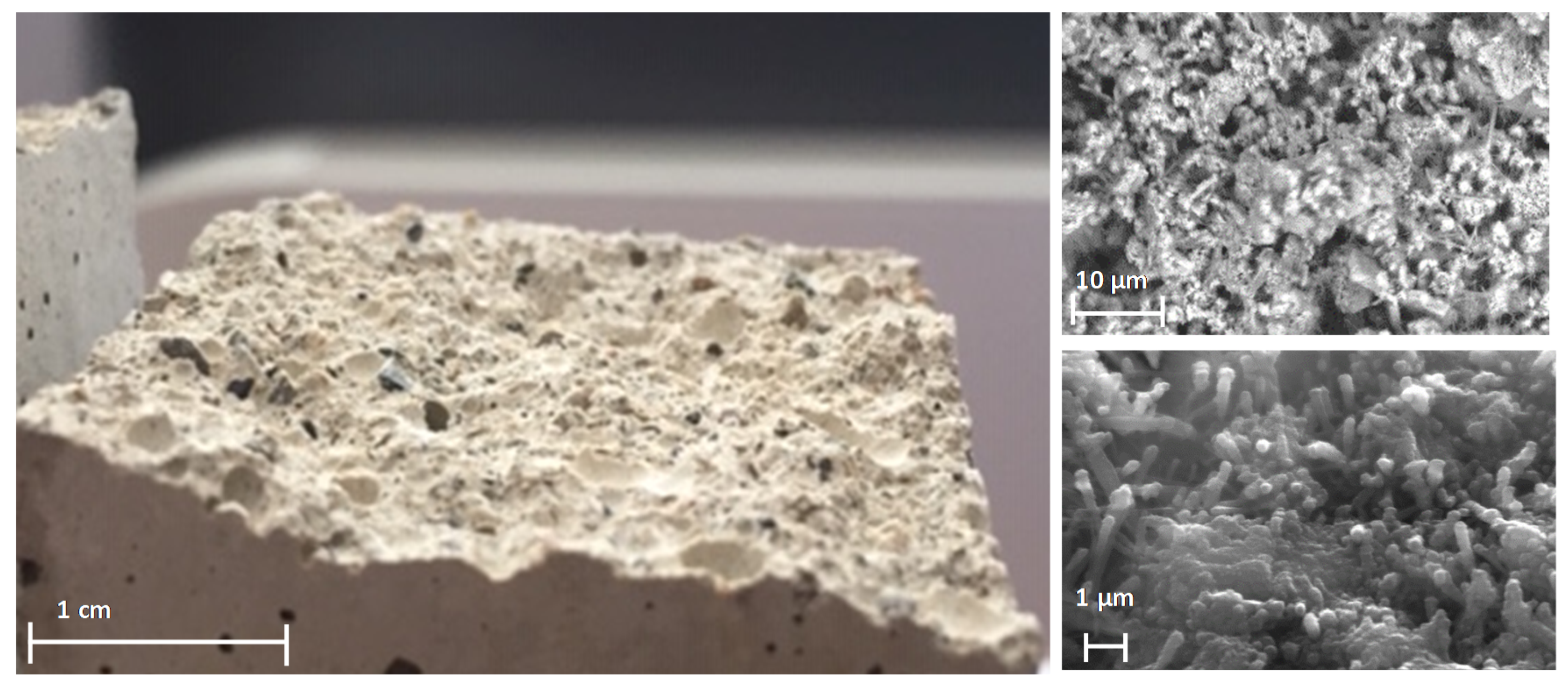
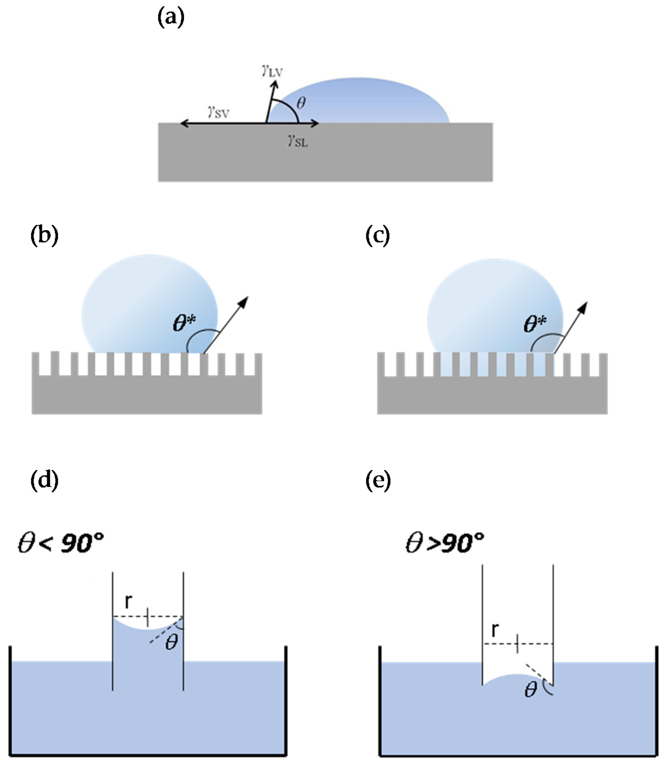
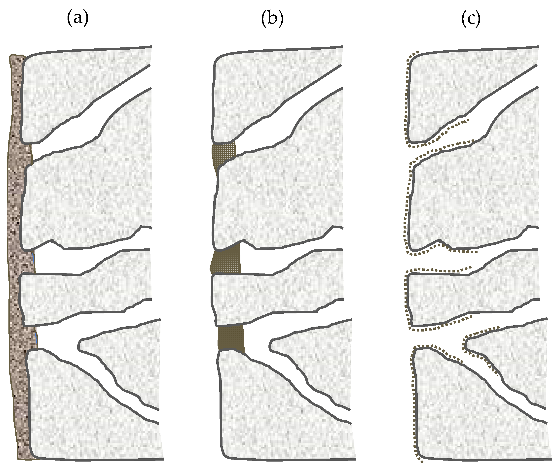
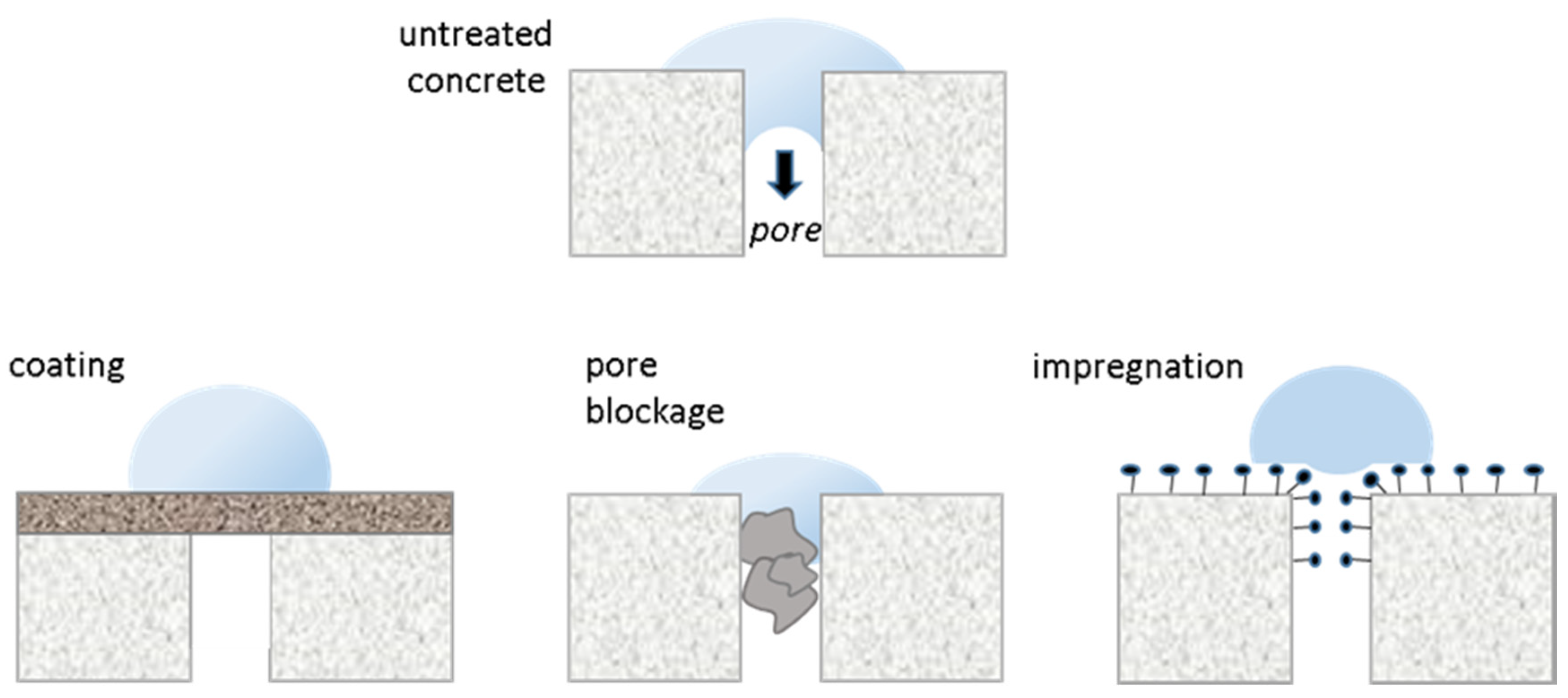
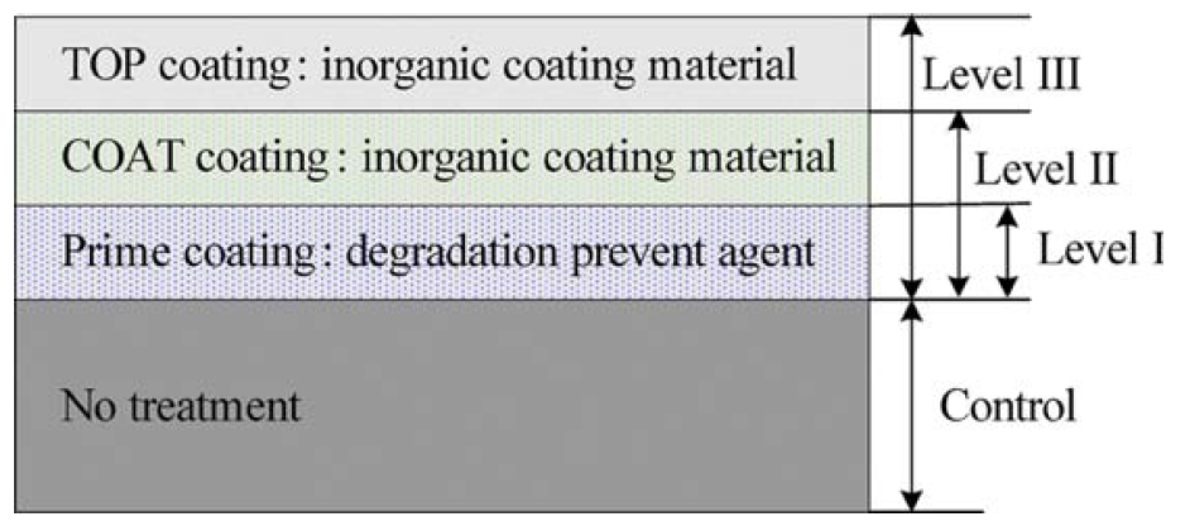
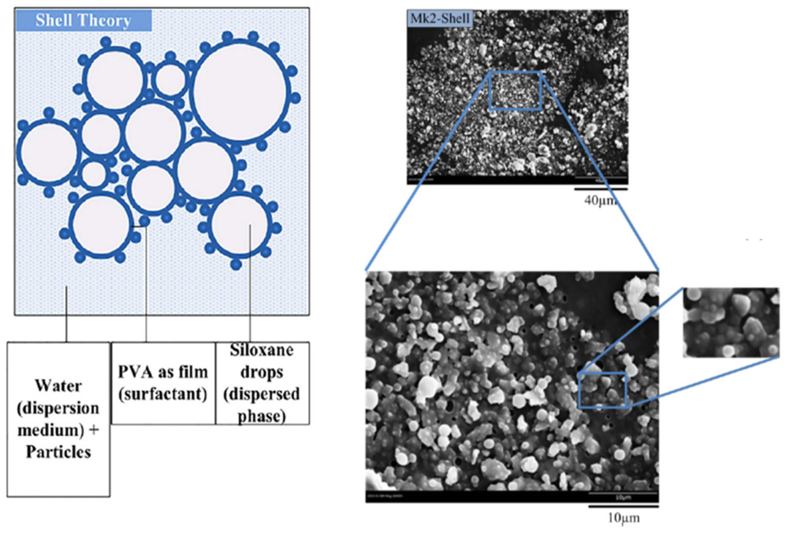
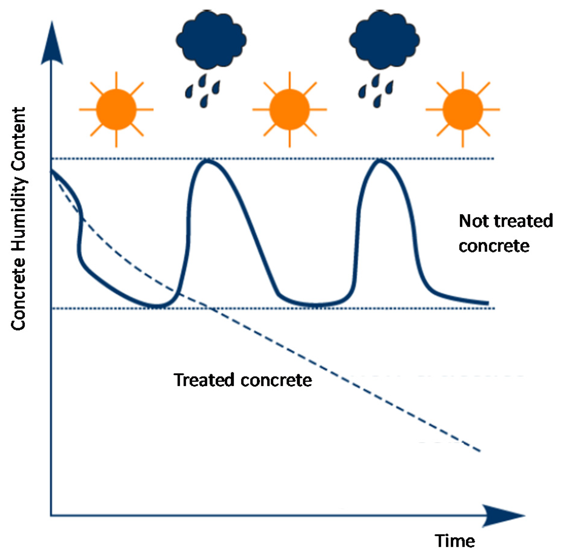
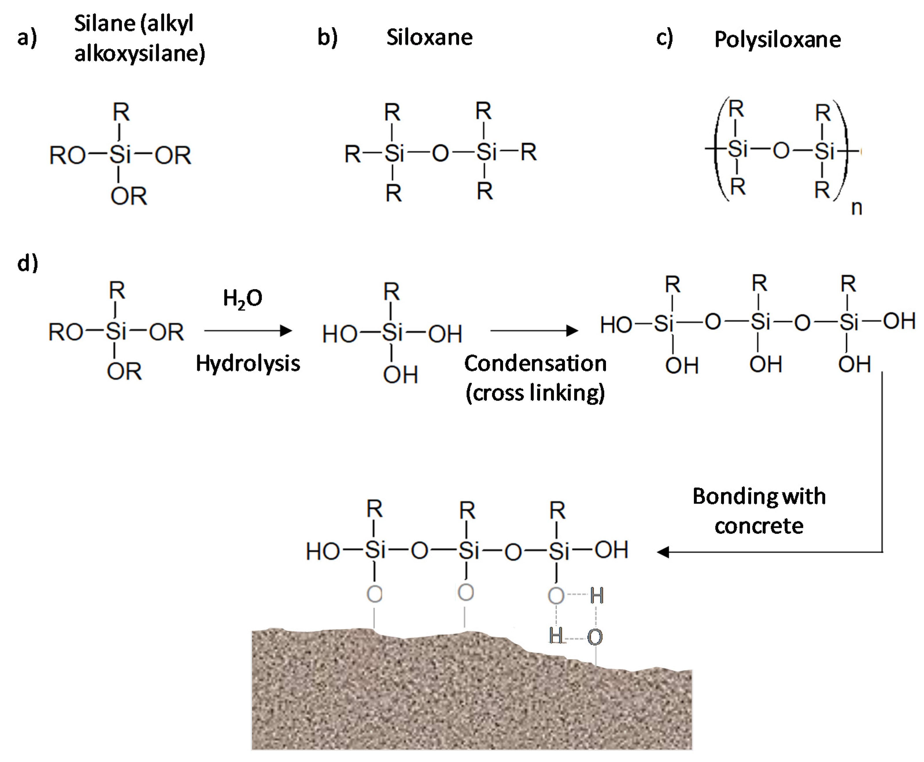
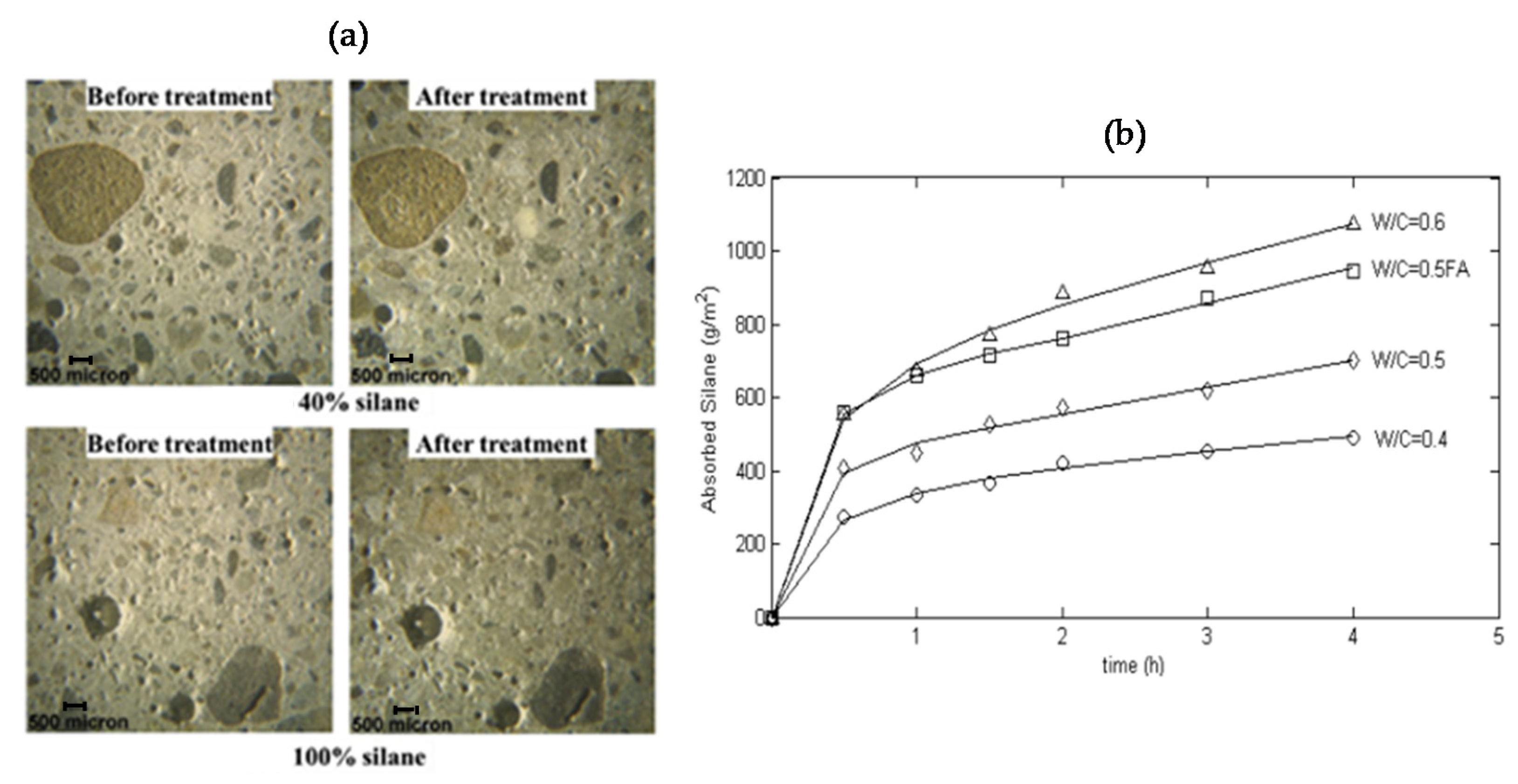
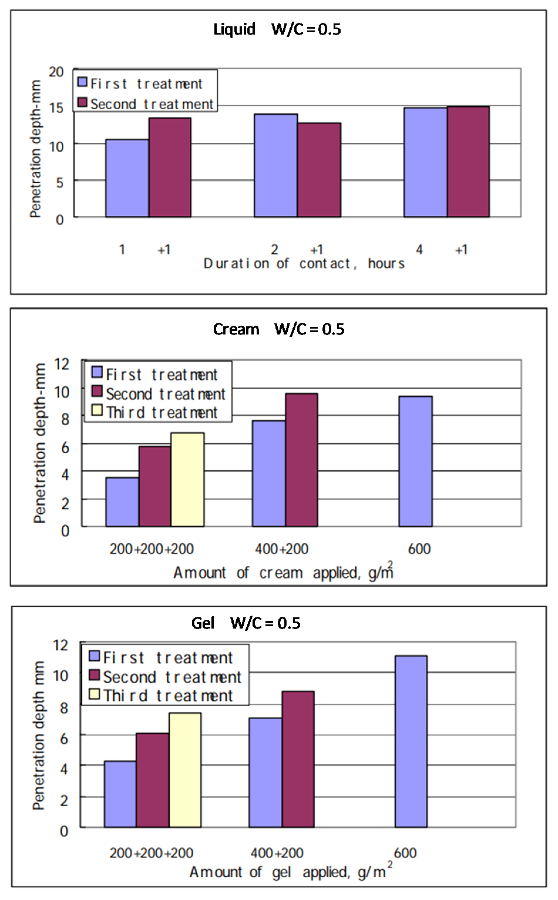
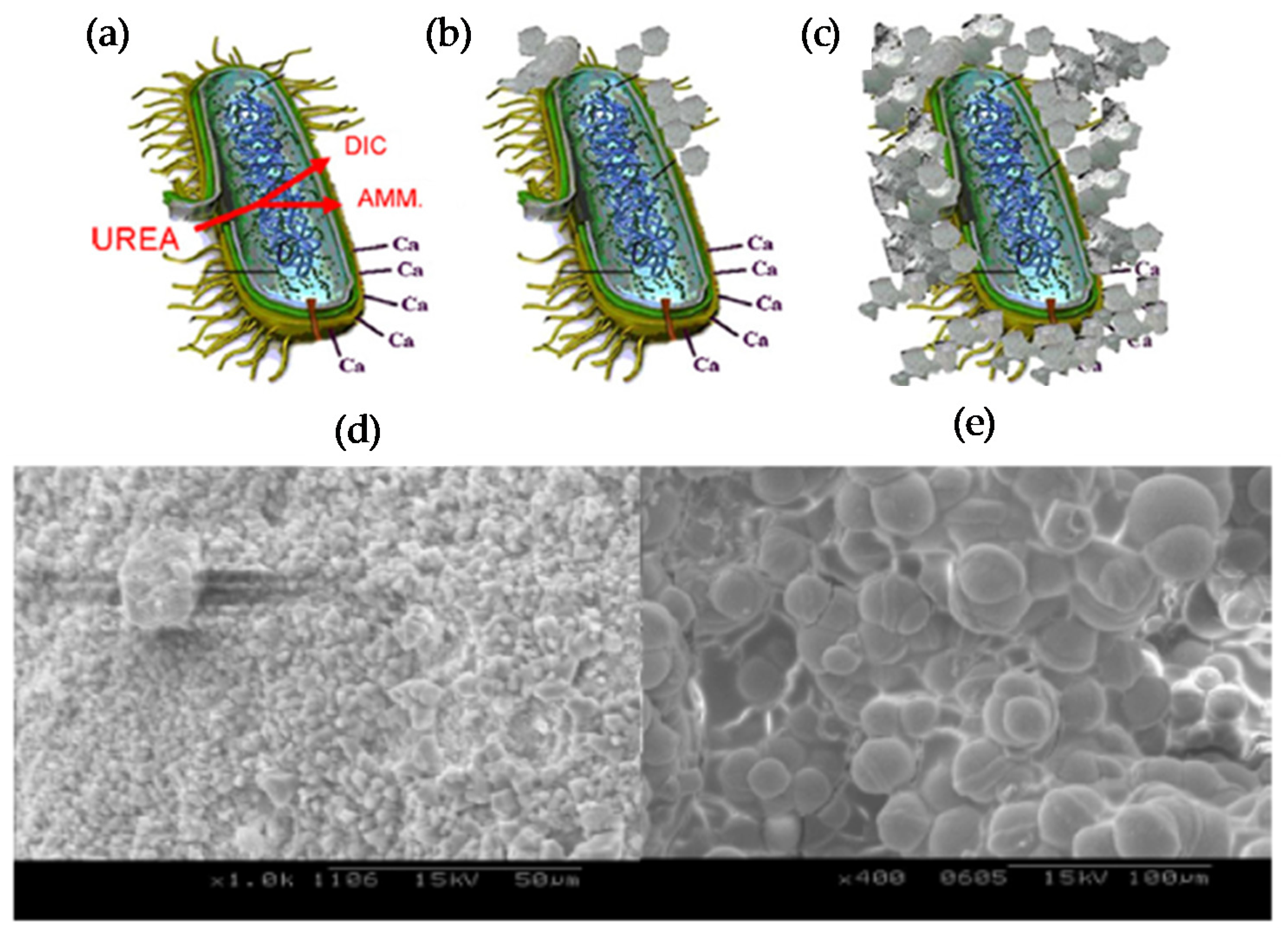
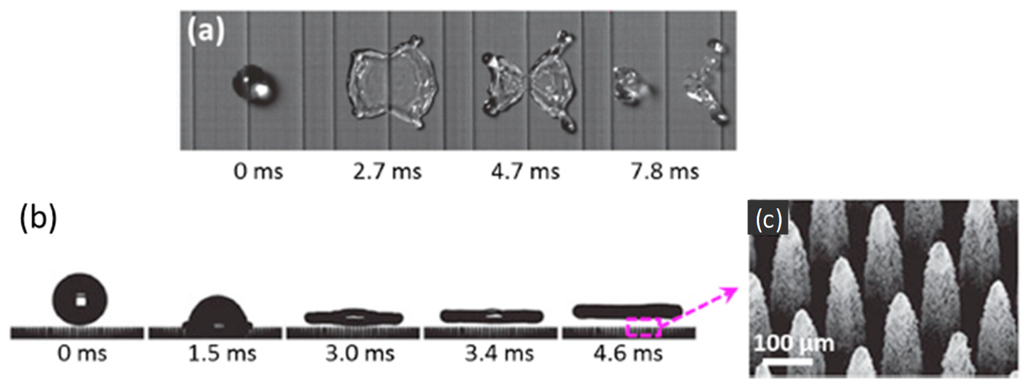
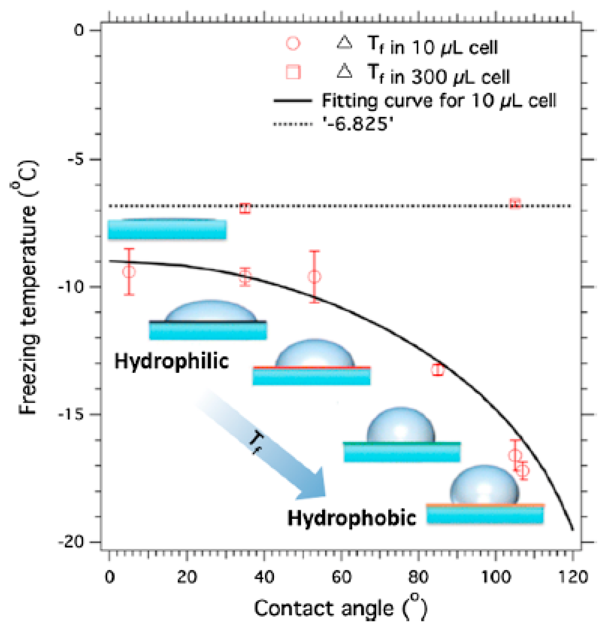
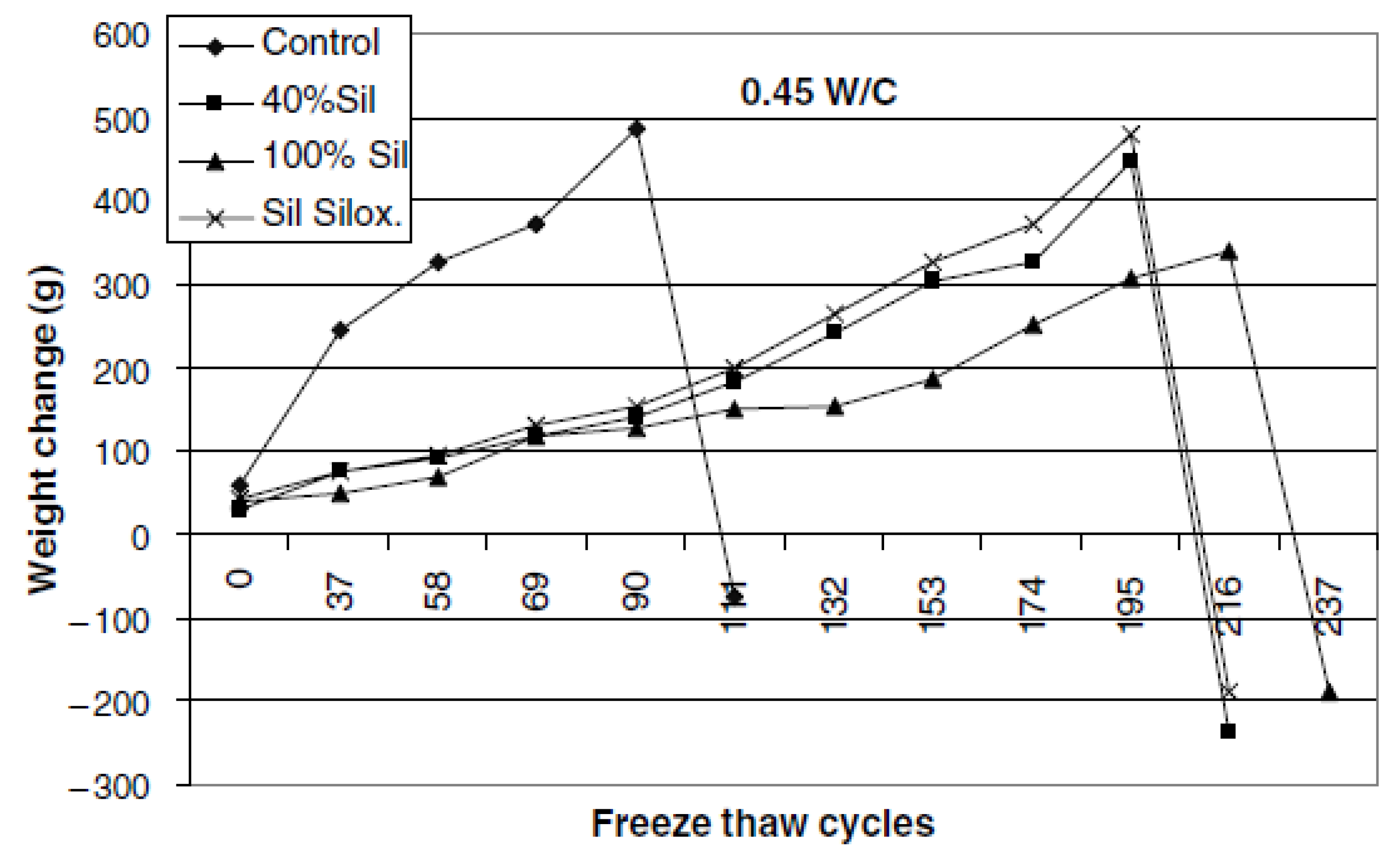
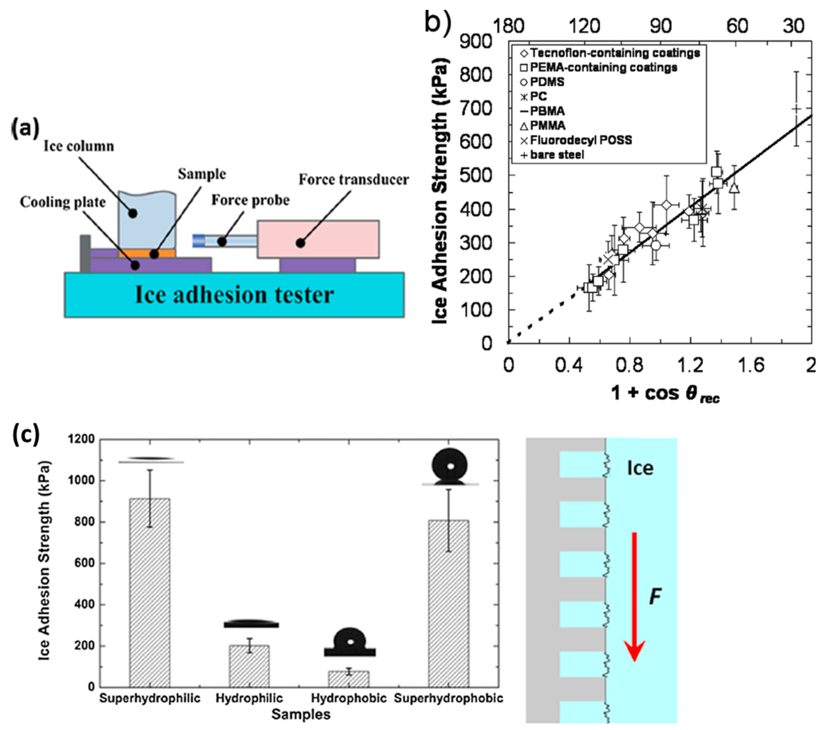
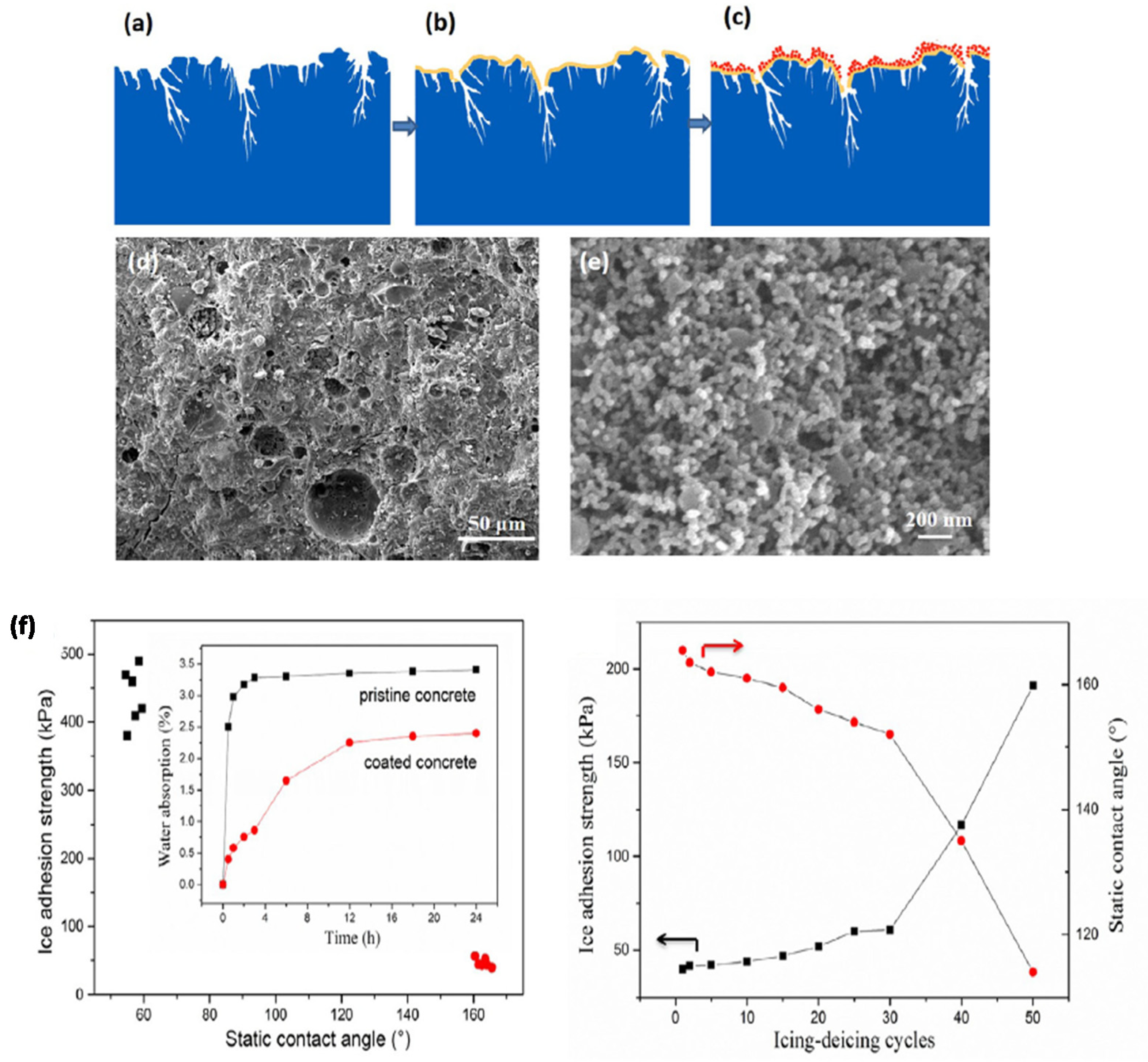
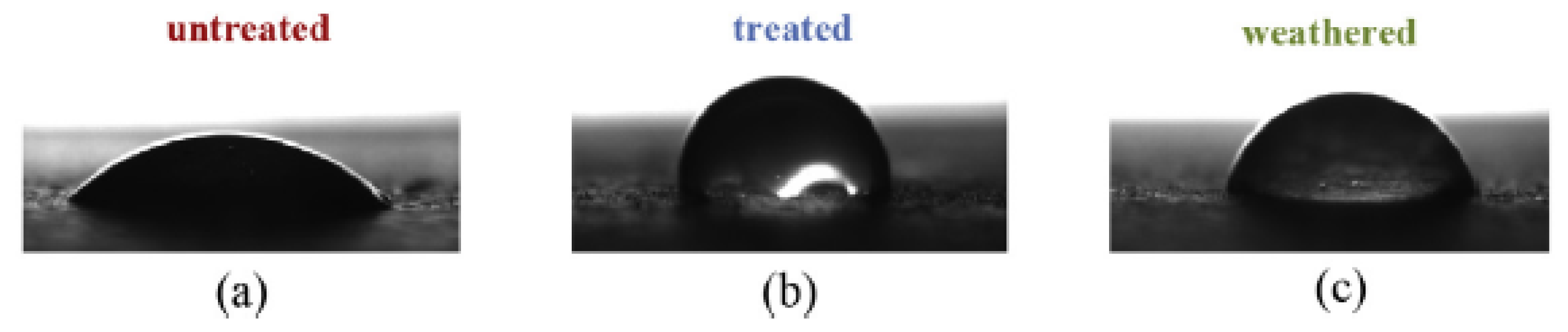
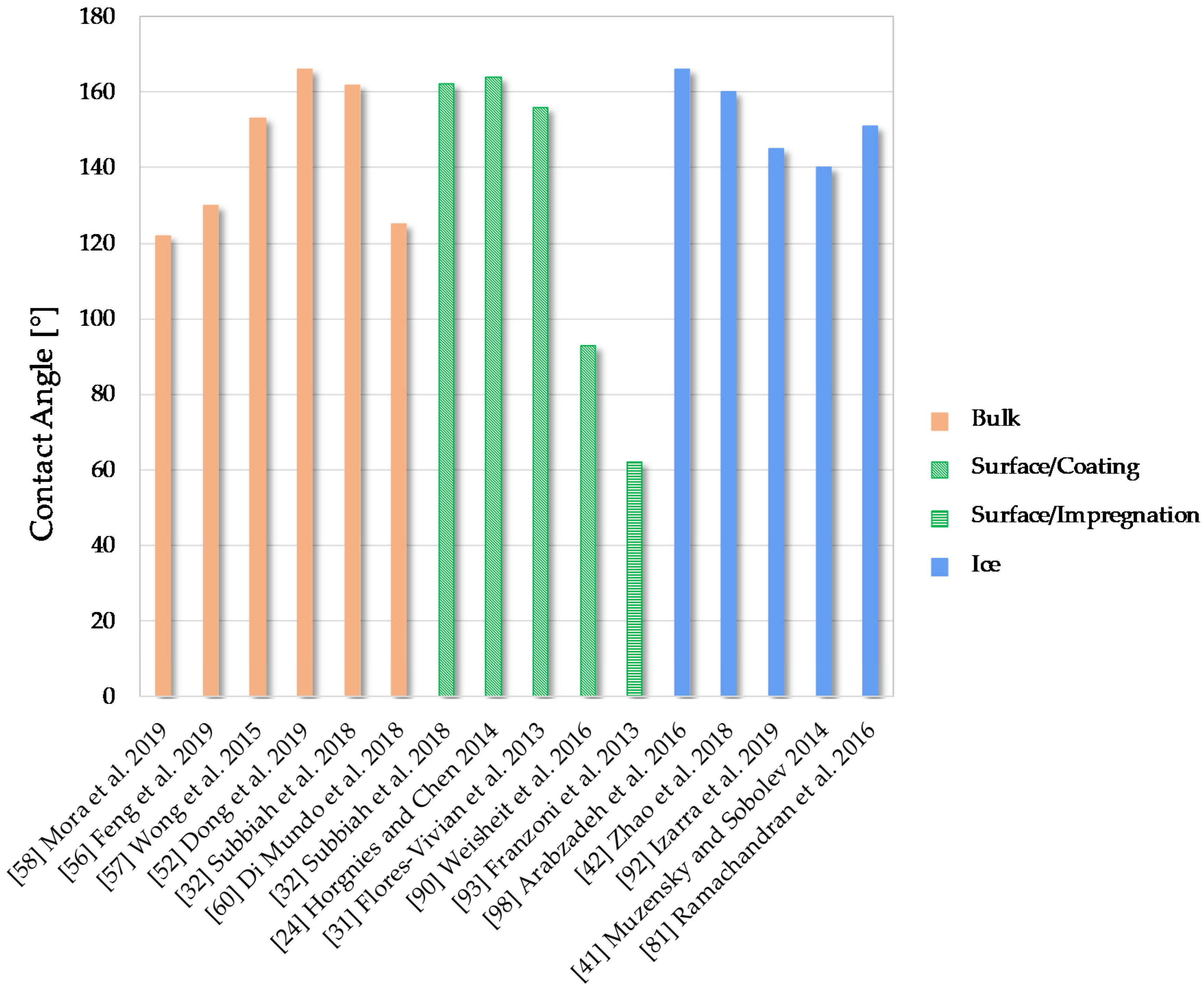
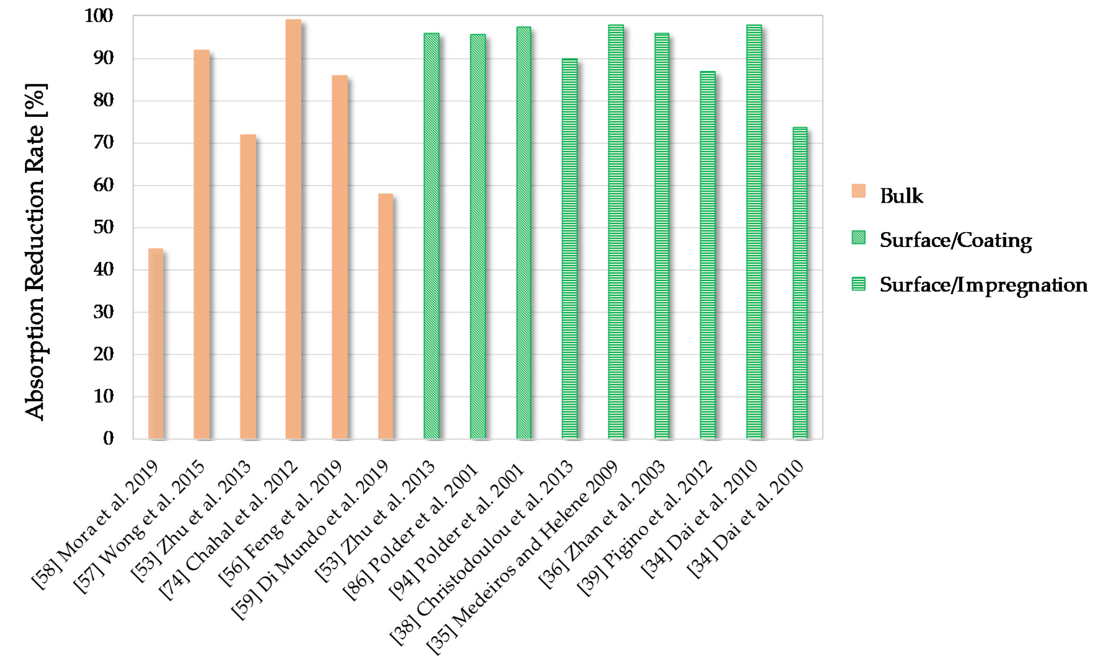
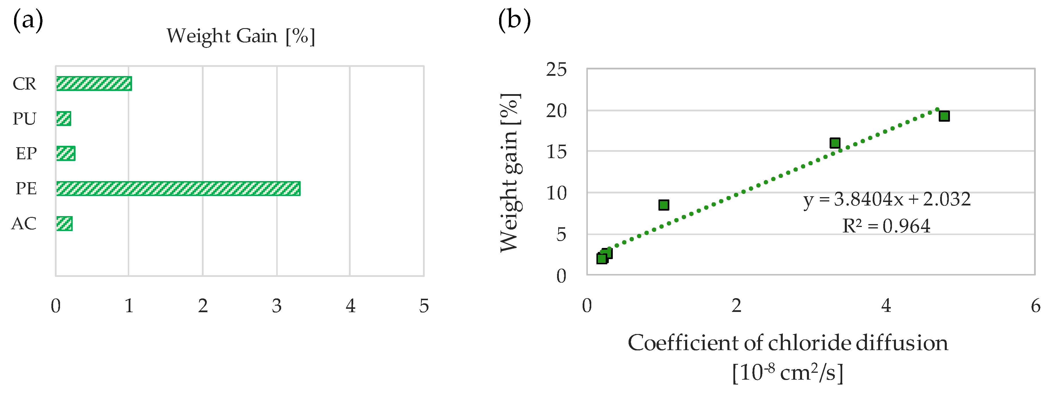
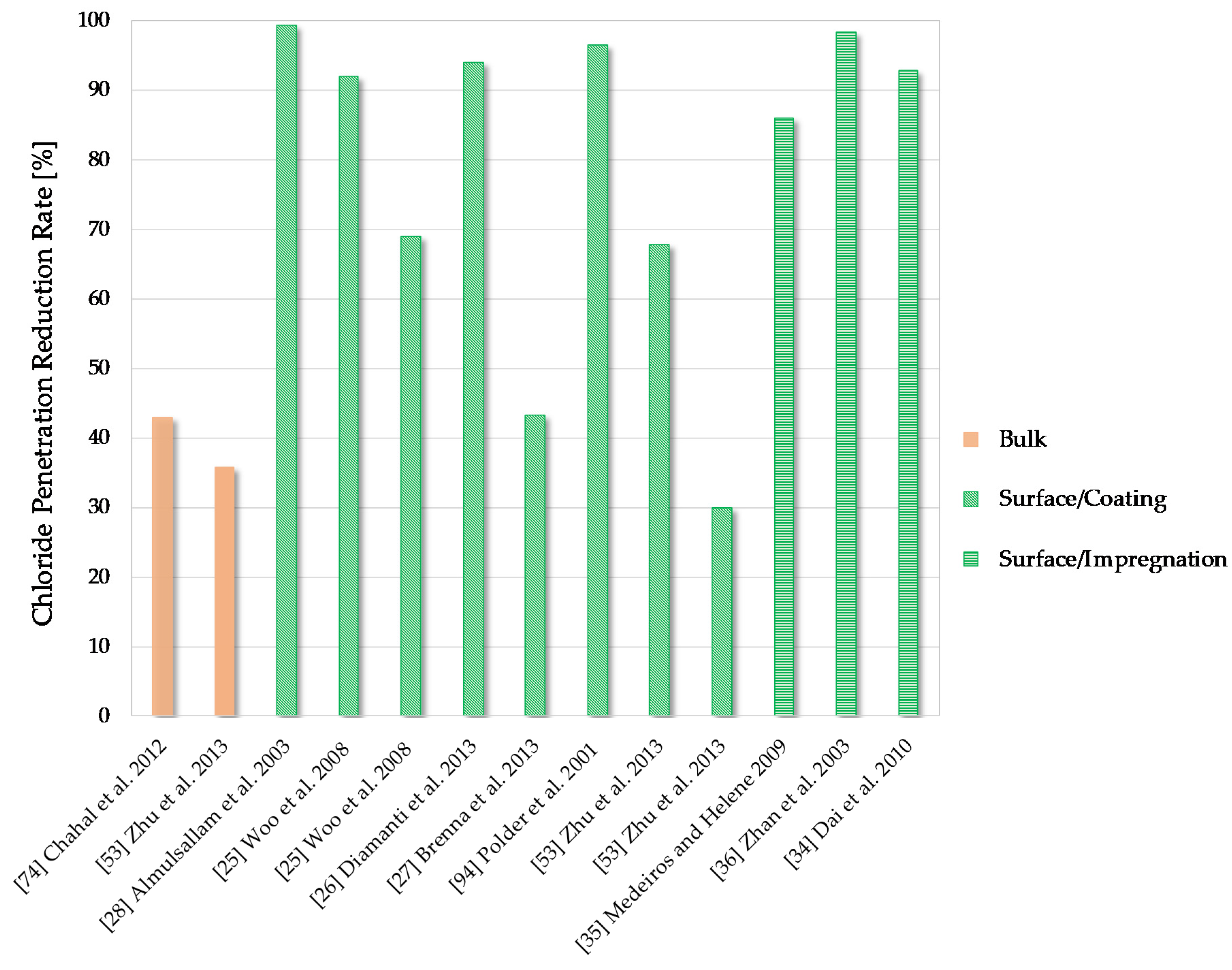
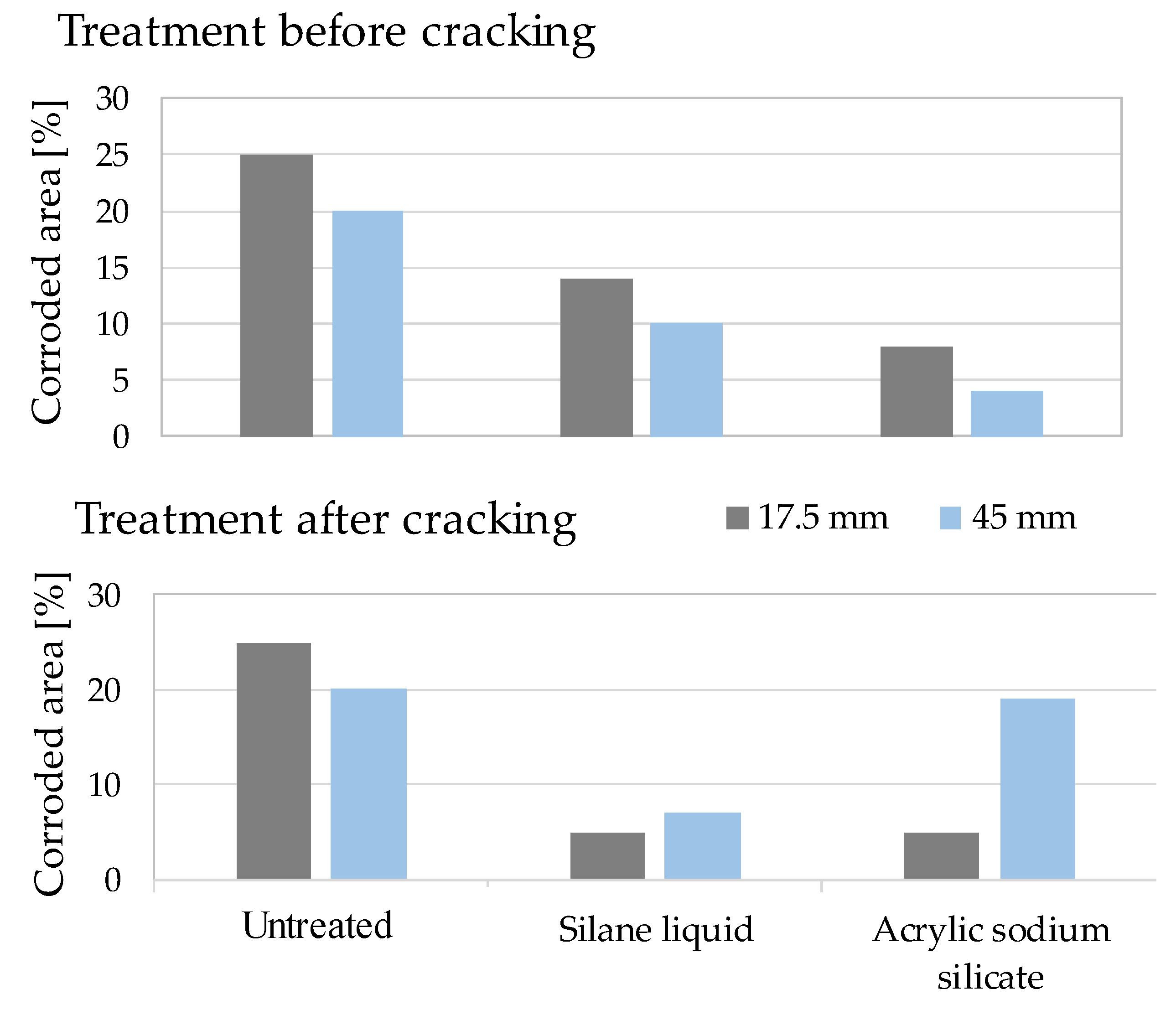
Table 1.
Summary of main compounds employed in hydrophobic surface treatments.
| Hydrophobic Surface Treatments | Compound and Version | Compound Molecular Structure | Reference |
|---|---|---|---|
| Coating | Silane/siloxane polymer ethanol diluted 1:7 w/w (Silres BS290) | Not Specified | [24] |
| Siloxane contamination from microtextured Polydimethylsiloxane (PDMS) mould | Not Specified | ||
| Mixture of octyltriethoxysilanes isomers, with iso-octyltriethoxysilane as the main component (SILRES BS 1701) |  | [25] | |
| Acrylic-based polymer mixed with cement | Not Specified | [26,27] | |
| Hydro-dispersed coating acrylic polymer | Not Specified | [27] | |
| Acrylic-based polymer mixed with sand | Not Specified | ||
| Acrylic resin-based paint in water dispersion | Not Specified | ||
| Polyurethane | Not Specified | [28,29] | |
| Chlorinated rubber | Not Specified | [28] | |
| Epoxy resin | Not Specified | ||
| Acrylic silicone mixture as outer layer and metal silicates as inner layers | Not Specified | [30] | |
| Polymethylhydroxysilane (PMHS) in emulsion with silica fume and polyvinyl alcohol |  | [31] | |
| 1H,1H,2H,2H-perfluorodecyltriethoxysilane (PFDTS) with nano TiO2 and SiO2 |  | [32] | |
| Pore Blockage | Sodium silicate |  | [33] |
| Acrylic sodium silicate (Silicate + acrylic resin) | Not Specified | [34] | |
| Impregnation | Silane-based (trietoxysilane, alkylalkoxysilane) |  | [34] |
| Silane/siloxane dispersed in water | Not Specified | [35] | |
| Silane/siloxane dispersed in solvent | Not Specified | ||
| Acrylic dispersed in solvent | Not Specified | ||
| Polyurethane | Not Specified | ||
| Isooctyl triethoxy silane/Isobutyl triethoxy silane |  | [36] | |
| Siloxane/oligosiloxane | Not Specified | [37] | |
| Silanes(alkyl alkoxysilanes) |  | [38] | |
| Tetraethoxysilane (Estel 1000) |  | [39] |
© 2020 by the authors. Licensee MDPI, Basel, Switzerland. This article is an open access article distributed under the terms and conditions of the Creative Commons Attribution (CC BY) license (http://creativecommons.org/licenses/by/4.0/).
Share and Cite
MDPI and ACS Style
Di Mundo, R.; Labianca, C.; Carbone, G.; Notarnicola, M. Recent Advances in Hydrophobic and Icephobic Surface Treatments of Concrete. Coatings 2020, 10, 449. https://doi.org/10.3390/coatings10050449
AMA Style
Di Mundo R, Labianca C, Carbone G, Notarnicola M. Recent Advances in Hydrophobic and Icephobic Surface Treatments of Concrete. Coatings. 2020; 10(5):449. https://doi.org/10.3390/coatings10050449
Chicago/Turabian StyleDi Mundo, Rosa, Claudia Labianca, Giuseppe Carbone, and Michele Notarnicola. 2020. "Recent Advances in Hydrophobic and Icephobic Surface Treatments of Concrete" Coatings 10, no. 5: 449. https://doi.org/10.3390/coatings10050449
Note that from the first issue of 2016, this journal uses article numbers instead of page numbers. See further details here.