Experimental Study on the Local Drag of Completion String with Packers in Horizontal Wells

1
School of Engineering and Technology, China University of Geosciences (Beijing), Beijing 100083, China
2
Petro China Research Institute of Petroleum Exploration & Development, Beijing 100083, China
3
School of Petroleum Engineering, China University of Petroleum-Beijing, Beijing 102249, China
*
Author to whom correspondence should be addressed.
Coatings 2020, 10(7), 657; https://doi.org/10.3390/coatings10070657
Submission received: 13 June 2020
/
Revised: 3 July 2020
/
Accepted: 6 July 2020
/
Published: 8 July 2020
(This article belongs to the Special Issue Advanced Nondestructive Evaluation and Characterization of Surface)
Abstract
:The multistage stimulation technology of horizontal wells has brought huge benefits to the development of oil and gas fields. However, the completion string with packers often encounters stuck due to the large drag in the horizontal section, causing huge economic losses. The local drag of the completion string with packers in the horizontal section is very complicated, and it has not been fully understood by theoretical calculations. A local drag experiment is designed to simulate the influence of microsteps and cuttings on the local drag of the completion string with packers in the inclined and horizontal sections. An obvious increase of the local drag of the packer is found at microsteps of the horizontal section, and the local drag is greatly affected by the amount of sand. In addition, the string with packers will vibrate during the tripping process in the deviated section, and the local drag is different when different amounts of sand are in the hole, but the change law is similar. The experimental results show that the friction coefficients of the packers with different materials in the horizontal section vary greatly, resulting in different local drags. It indicates that the local drag of the completion string not only depends on the microsteps and sand quantity in the wellbore, but also on the material difference of the packers. Only if microsteps and cuttings are removed can the completion string be tripped into horizontal wells smoothly.
1. Introduction
The horizontal well technology has been maturely applied in the development of oil and gas fields, and the extension record of horizontal wells has been continuously updated with the development requirement and technological advancement [1,2,3]. With the development of the directional drilling technology and measurement tools, many kinds of complex-structure wells have been drilled on the basis of horizontal wells [4,5], such as U-shaped wells [6,7,8], multilateral wells [9,10,11,12], and steam assisted gravity drainage (SAGD) wells [13].
With the advancement of the completion technology, more and more horizontal sections of horizontal wells are not cemented and stimulated to increase production [14]. The stimulation technique is commonly used in low permeability reservoirs [15,16], such as dolomite reservoirs [17] and tight gas reservoirs [18]. There are many kinds of fracturing technology, and the acidizing fracturing is the most effective one to bring the best stimulation results in many oil and gas fields [19,20,21]. However, the completion string with packers (as shown in Figure 1) frequently gets stuck in the horizontal section and fails to run into the bottom of the horizontal wells due to high drags, and the sticking accident is more likely to occur in these horizontal wells with long horizontal sections, resulting in well abandonment and huge economic losses [22,23,24].
From the aspect of tubular mechanics, a great deal of theoretical research has been done about the tripping ability of the completion string. According to the well trajectory, Wang [25] established the frictional prediction models of the completion string according to the “rigid rod model” and “soft rod model”, respectively, and created the mathematical solution method of the model to predict the maximum running depth of the completion string. Based on the “rigid rod” model, the completion tools, and wellbore size curvature, Cai [26] believed that the completion string sticking due to the large overall friction can be controlled by optimizing the spacing of centralizers in the completion string. Liu [27] established a friction model considering the completion string stiffness and packers, and results of the case study showed that the borehole curvature and string combination structure are two main factors affecting the tripping ability of the fracturing strings in horizontal wells. These researches mainly focused on the overall stress analysis of the completion string under the assumption that the borehole is smooth, and did not consider the local drag of packers and centralizers of the completion string with a larger size in irregular horizontal intervals. Therefore, in many cases, completion strings actually still got stuck even though the theoretical calculation is going well, and cannot be run into the bottom of the horizontal well. However, the geometry of the actual wellbore is irregular and with microsteps or keyslots in it due to the enlargement or shrinkage of the local open hole section [28], which can be easily found from the log caliper, or the presence of downhole cuttings which have been confirmed by lots of experimental and theoretical research [29,30,31,32]. These microsteps, cuttings beds, and different types of packers with different materials, making the local drag of the completion string with packers is very complicated. The local drag is very hard to be well studied through theory alone, as a result, the actual drag of the whole completion string is quite different from the theoretically calculated one.
To find the change characteristic of the local drag with relevant factors, and provide support for the establishment of local drag models and determination of friction coefficients, simulation experiment programs were designed. The local drag of the packer was tested under four kinds of horizontal open hole states: Clean and regular wellbore, hole with microsteps, with cuttings, and with both microsteps and cuttings. For the local drag of the completion string with packers in the cased deviated section, experiments were conducted under three kinds of wellbore states: Wellbore without cuttings, with a small amount of cuttings, and a large amount of cuttings. In addition, the local drag of the cement column combined with the packer rubber cylinder and the hard plastic cylinder were tested.
2. Materials and Methods
2.1. The Packer in the Horizontal Open Hole
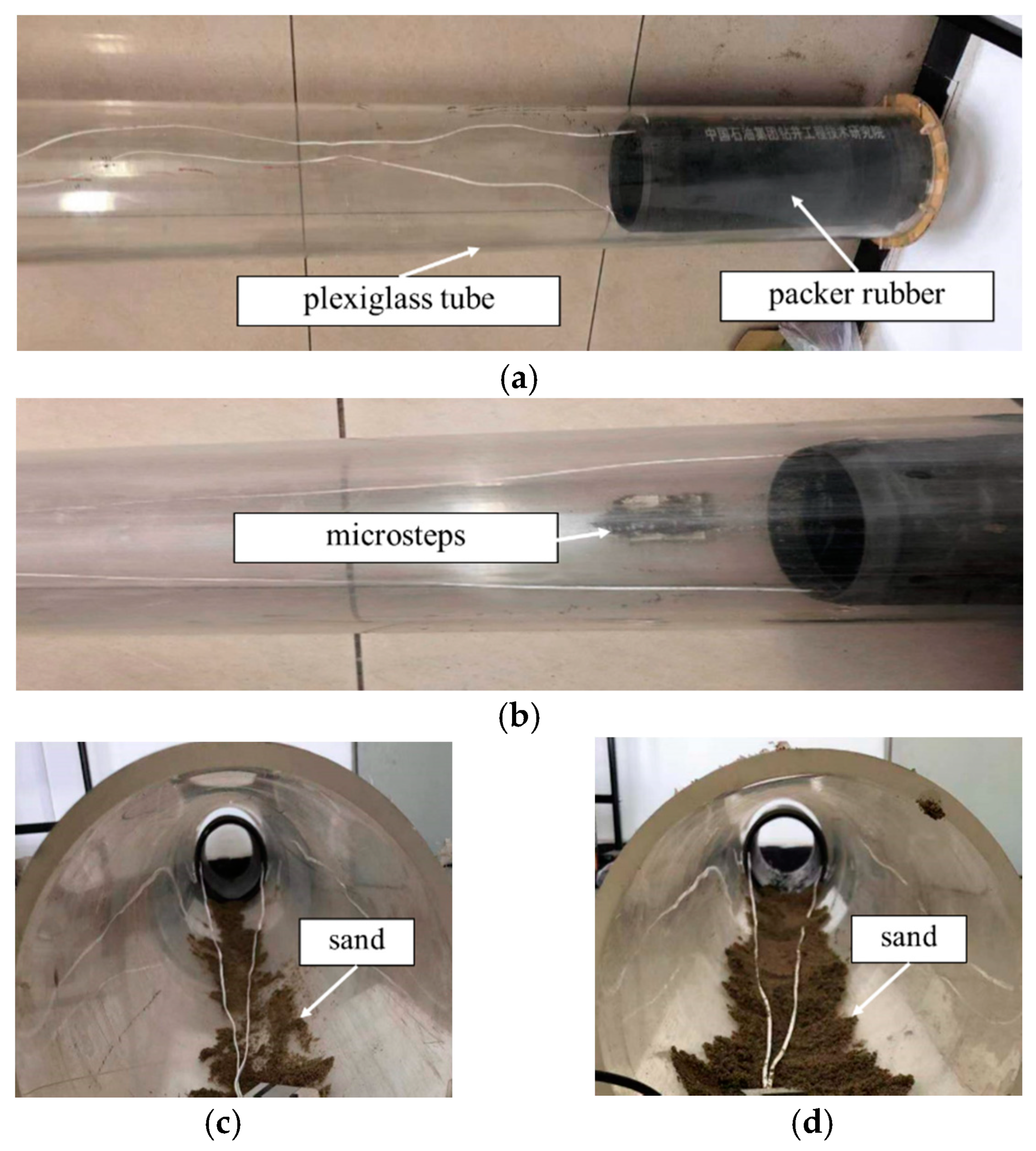
In this experiment, a straight plexiglass tube (OD 240 mm, ID 220 mm, length 2 m) was used to simulate the horizontal hole section, a packer rubber (OD 200 mm, length 0.56 m, weight 97 N) was used to simulate a packer, and some river sand particles were used to simulate the downhole cuttings. The packer rubber was placed in the horizontally placed plexiglass tube, and the local drag tests were conducted by recording the axial force during pulling of the packer rubber in a horizontal open hole, as shown in Figure 2a.
The shape, height, and position of actual microsteps in a horizontal section cannot be known accurately, and they cannot be simulated and analyzed quantitatively by an experiment either, but the drag change characteristics when the packer passes through the microsteps can be studied. The drag tests in a horizontal open hole with microsteps can be conducted by fixing a piece of rubber in the lower side of the plexiglass tube, as shown in Figure 2b.
In many cases, cuttings are left in the horizontal section and it will seriously affect the drag of the completion string with packers, but it is impossible to predict and calculate the quantity of the downhole cuttings accurately. In order to find the influence of downhole cuttings on the local drag of the packer in the horizontal section, the experiments were conducted by putting some river sand (OD 1.0–4.0 mm, bulk density 1.6 g/cm3) in the plexiglass tube with proper water under two kinds of conditions: The borehole has little (about 500 g) and lots of sand (about 1600 g), as shown in Figure 2c,d, respectively.
2.2. The Completion String with Packers in the Deviated Cased Hole
When the completion string with packers passes through the deviated section, the local drag of the packer will be influenced by the dogleg severity of the well trajectory and downhole cuttings, but microsteps are not needed to be considered in this cased section. Therefore, this simulation experiment was specially designed to study the variation characteristics of the local drag. A metal pillar wrapped by a packer rubber (OD 70 mm, length 0.1 m, weight 7.5 N) was used to simulate a packer, as shown in Figure 3a, a deviated plexiglass tube (OD 100 mm, ID 90 mm, length 4 m, curvature radius 2 m) was used to simulate the deviated wellbore, a PVC tube (OD 20 mm, ID 15 mm, length 4.5 m) to simulate the completion string, and little and lots of river sand were used to simulate the downhole cuttings. The packer rubber is placed in the bent plexiglass tube, and the drag test in the clean wellbore can be conducted by recording the axial force during pulling of the packer rubber, as shown in Figure 3b. Put some river sand (OD 1.0–4.0 mm, bulk density 1.6 g/cm3) into the simulated wellbore, and the influence of little (about 600 g) and lots of (about 2000 g) sand on the local drag can be tested, as shown in Figure 3c,d, respectively.
2.3. Packers with Different Materials in the Horizontal Section
The experiment programs were designed to study the local drag of packers with different materials, and provide support to establish local drag models and to determine friction coefficients. A rubber cylinder (OD 240 mm, ID 220 mm, length 0.56 m) was used to simulate the wellbore, a cement column (OD 100 mm, length 0.16 m, weight 35 N) in Figure 4a was used to simulate a packer as shown, and river sand (OD 1.0–4.0 mm, bulk density 1.6 g/cm3) was used to simulate downhole cuttings.
The cement column was put in the horizontally placed rubber cylinder, and the drag test in the clean wellbore can be conducted by pulling the cement column and recording the friction force, as shown in Figure 4b. The influence of cuttings on the local drag of the packer can be tested by putting little (about 200 g) and lots of (about 500 g) river sand into the rubber cylinder, as shown in Figure 4c,d.
Finally, the cement column was placed in a hard plastic cylinder (OD 170 mm, ID 160 mm, length 0.56 m) to find the variation of experimental results of different material combinations.
3. Results and Discussion
3.1. The Local Drag of the Packer in the Horizontal Open Hole
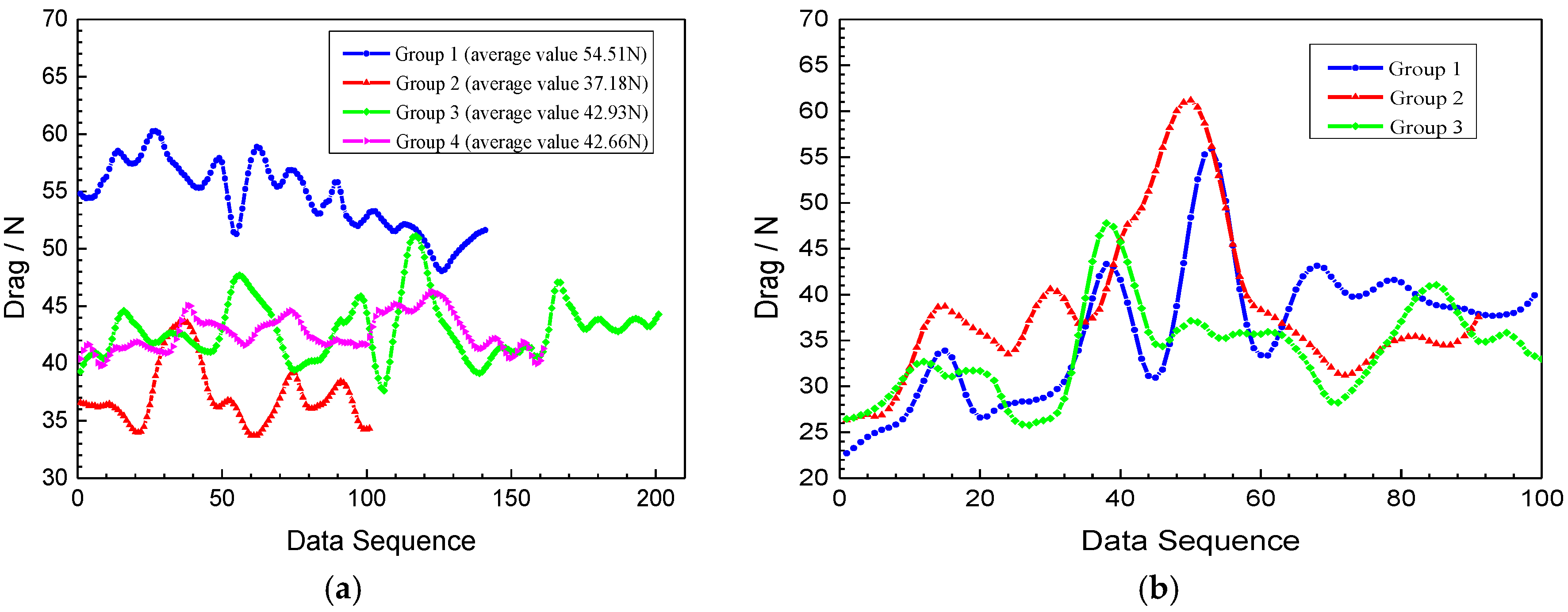
According to the experiment shown in Figure 2, many groups of the local drag test have been done for the packer in the smooth horizontal open hole, and typical experimental results are shown in Figure 5a, in the same way, the typical local drag results in the horizontal hole with microsteps are shown in Figure 5b.
The average value of each group of the experimental result is 54.51, 37.18, 42.93, and 42.66 N, and the average value of these four groups is 44.32 N. Therefore, the average friction coefficient between the packer rubber and the plexiglass is 0.4569 (44.32/97 N). It can be seen from Figure 5a that the drag is strongly influenced by the packer’s moving speed. Since the loading method is not displacement controlled with a uniform speed, the experimental value varies greatly from one group to another. In an actual operation, the tripping speed of the completion string in the horizontal open hole section also cannot be accurately controlled due to many factors, which is manifested by the obvious vibration of the local drag of downhole packers. By comparing these three curves in Figure 5b, it can be found that the drag increases significantly and forms a peak value, when the packer passes through the microsteps in the horizontal section. The peak value will be more than 20% larger than the average value of the stable stage, then the drag curve will be stable and smaller than that in the horizontal section without microsteps. It can be found that the drag curve is relatively stable in the horizontal section without microsteps.
The local drag of the packer in the horizontal hole has been studied under different sand contents, namely, the hole with little and lots of cuttings separately. Test results are shown in Figure 6.
When there is a small amount of sand in the horizontal section, the drag curve has a downward trend and it would be less than that in a clean wellbore without sand. The reason for the drag reduction is the rolling effect of sand particles. The presence of a large amount of sand particles will cause an increase tendency in the drag curve, drag results are greater than that in the clean wellbore without sand, because of the accumulation effect of sand particles. Despite the fact that the large amount of sand particles was added, the sticking phenomenon was not encountered in these experiments.
In order to find the influence of both cuttings and microsteps on the local drag of the packer when it passes through the horizontal section, experiments were conducted by putting different amounts of sand in the simulated wellbore with microsteps. Three groups of test results when a small amount of sand in the wellbore and two typical groups when the wellbore has a large amount of sand are shown in Figure 7.
During the time that the packer passes through the horizontal section with microsteps and sand, the drag increases significantly and forms a peak value when the packer contacts the microsteps, but the formed peak is not closely related to the sand quantity. The drag peak of the packer in the hole with sand is larger than that in the clean hole. The drag increases significantly after the peak point if the wellbore has a large amount of sand, which is mainly due to the increased drag caused by sand accumulation.
3.2. The Drag of the Completion String with Packers in the Deviated Cased Hole
According to the experiment program shown in Figure 3, the drag tests were performed for the completion string with packers in the deviated cased hole. A typical drag curve of the whole process of the completion string with a packer moves in the clean deviated section, as shown in Figure 8a. Stable sections of six groups of typical drag curves are shown in Figure 8b.
There are two consecutive “up-stable-down” processes in the drag curve of the completion string with the packer when it passes through the clean deviated section, indicating that the tripping process is unstable due to the vibrations of contact force and friction coefficient. It can be seen that the local drag varies obviously in each curve, but their maximum values are relatively close to each other. The drag is the total friction force in each curve, and the average value of six groups is 13.63 N, but the friction coefficient can only be obtained after calculating the total contact force.
Many groups of drag tests have been done in the deviated section with little sand particles. Due to the different quantity and distribution of those sand particles, the drag curve of completion string with the packer is various in different test groups, and a typical one is shown in Figure 9a. Since the drag curve is not stable, only a small section near the maximum value in each test is taken and shown in Figure 9b.
From Figure 9a, it can be found that the drag curve will reach its maximum value after a long ascending section, and then without ascending and stable periods. It indicates that sand rolling can reduce the friction force in the early stage of the moving process, and then this effect disappears. The maximum drag value in each experiment group in Figure 9b is larger than that in the deviated section without sand (13 N).
Many groups of drag tests of the completion string with the packer have been done in the deviated section with a large amount of sand particles, and the drag curves depend on the quantity and distribution of sand particles. A typical drag test curve is shown in Figure 10a. Since the drag curve is unstable, and the drag sections around the maximum value are shown in Figure 10b.
When there is a large amount of sand particles in the deviated section, the drag curve is similar to that in the wellbore that has little sand, but the drag variation trend is obviously affected by sand accumulation rather than sand rolling. The maximum drag value in each experiment group is greater than that in the deviated section that has no or little sand. It can be seen that the drag curve varies with sand quantity, and the maximum drag increases with the sand quantity, but the sticking was not encountered.
3.3. The Drag of Packers with Different Materials in the Horizontal Section
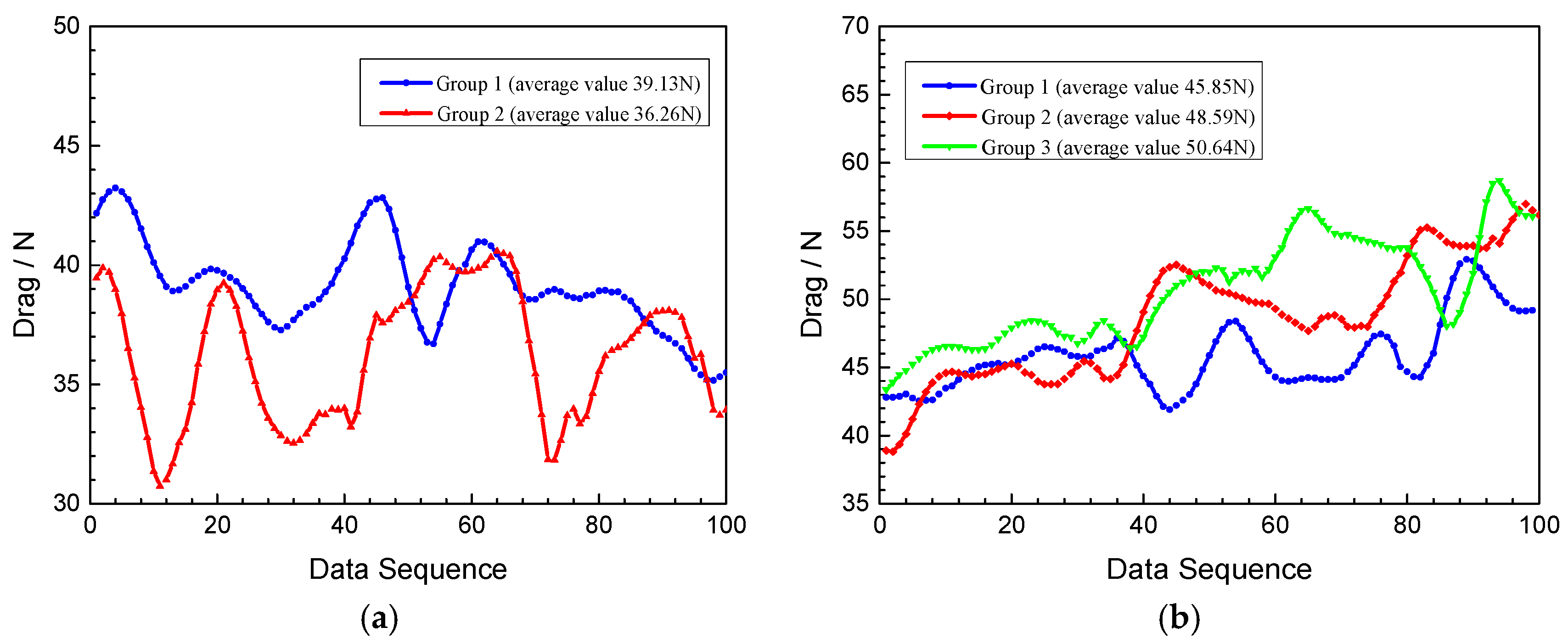
Multiple groups of the local drag experiments have been conducted with the combination of the rubber cylinder and the cement column, as shown in Figure 4. Two groups of typical drag results at their early stages of test processes are shown in Figure 11a, and three groups of typical drag results at their stable stage are shown in Figure 11b.
Due to the rough surface of the cement column, it can be found in Figure 11a that the drag increases at the beginning of the moving process and then reaches a peak value, and then decreases to a relatively stable level. Although the drag curve is different in each group, the peak value is nearly the same and it is obviously larger than that at the stable stage in Figure 11b. The average value of these three curves is 14.52 N, so the friction coefficient between the rubber cylinder and the cement column is 0.415 (14.52/35 N). This large friction coefficient is caused by the rough surface of the cement column and the relatively soft material of the rubber cylinder.
Four groups of typical drag results in the wellbore with a small amount of sand particles are shown in Figure 12a. Drag curves change with the increase of the sand quantity in the wellbore, and three drag curves are shown in Figure 12b. Drag curves when a large amount of sand is in the wellbore are shown in Figure 12c. Finally, the drag curve when huge amounts of sand particles are in the hole is shown in Figure 12d.
It can be seen from Figure 12b that the drag increases to reach a peak value and then keeps it, which is mainly affected by the increasing sand accumulation in the wellbore. Figure 12c shows that the drag further increases to form a peak value and then decreases, which is mainly affected by a lot of sand particles accumulated in the wellbore. The main reason for the stable curve after the peak value in Figure 12d is that huge amounts of sand particles are piled in the wellbore.
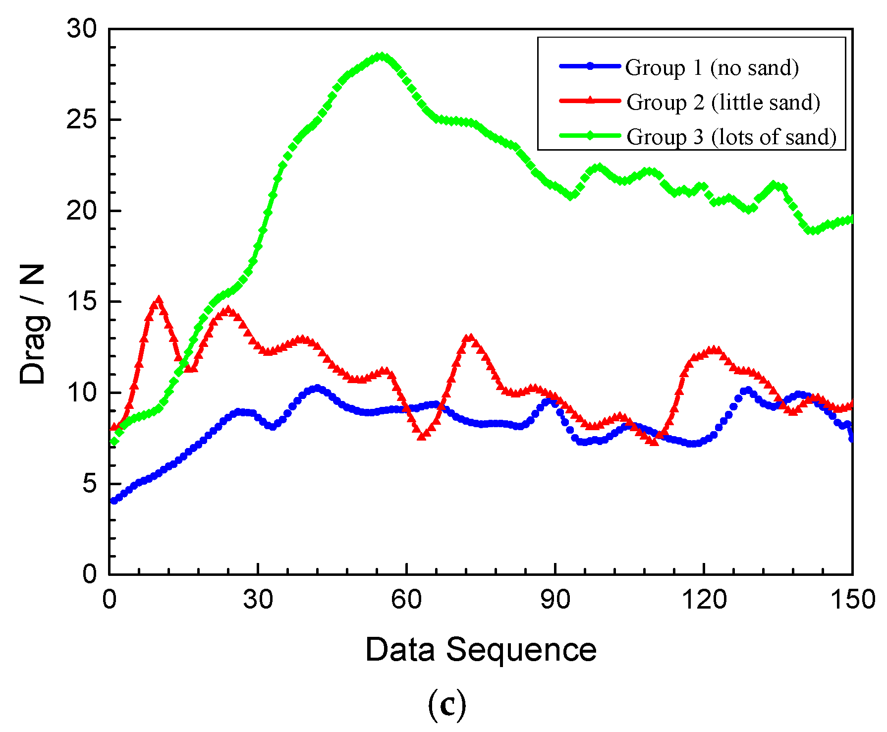
Figure 13a shows stable sections of three groups of typical drag curves of the cement column in the hard plastic cylinder. When a small amount of sand particles are in the hard plastic cylinder, local drag results in the early stage of the test process in each test group are shown in Figure 13b. If the hard plastic cylinder has lots of sand particles, then local drag results of the cement column are shown in Figure 13c.
It was found in Figure 13a that the drag curve decreases to a relatively stable level after its peak value in each group, which is similar to the drag result of the cement column in the rubber cylinder. The average value of these three groups is 9.23 N. Therefore, the friction coefficient is 0.2637 (9.23/35), which is significantly smaller than that between the rubber cylinder and the cement column, which is mainly due to the fact that the hard plastic cylinder is harder and with a smaller elastic deformation than the rubber cylinder.
It can be found from Figure 13b that the peak value of these three curves are larger than that in the clean wellbore, which shows the opposite experimental phenomenon when the cement column is in the rubber cylinder. The possible reason for that is the sand particles’ various influence performance in different combinations, resulting in a large friction coefficient of the cement column in the rubber cylinder (the average experimental value is 0.415) and a smaller one in the hard plastic cylinder (the average experimental value is 0.2637).
The results in Figure 13 demonstrate that the local drag curves of the cement column are different in the hard plastic cylinder with a different sand quantity: Each drag curve with local fluctuation but overall stable tendency when the hard plastic cylinder has no sand particles; the overall trend of the drag curve declines with the great fluctuation when the hard plastic cylinder has little sand particles, but the peak value increases. The peak drag increases further when the hard plastic cylinder has lots of sand particles, and the drag curve declines gently with little fluctuation after the peak.
4. Decisions
The above experimental results confirm that the microsteps and cuttings in the wellbore can have a significant impact on the local drag of the completion string with packers. Therefore, it is necessary to fully condition the borehole before the completion string trips in the horizontal well [33,34,35]. In severe cases, special tools such as the watermelon milling cone and reamer are even used to completely remove the microsteps in the wellbore and to create a smooth wellbore. In addition, RSS should be recommended as the directional drilling tool in horizontal wells with long horizontal sections [36,37].
Although experiments have shown that the rolling effect of a small amount of sand can reduce the friction between packers and boreholes, it is very easy to bring an additional local drag due to the accumulation of downhole sand. Therefore, before the completion string enters the horizontal well, the drilling fluid performance needs to be adjusted to meet the requirement of carrying cuttings [38,39,40], and the drilling fluid lubricity should be improved to reduce the friction coefficient between the completion string and the wellbore. In addition, it is necessary to use enhanced operation parameters when pumping on and circulating the drilling fluid at the bottom of the well, such as high flow rate of the drilling fluid and the rotation speed of the drill string [41,42]. Some special tools such as the cuttings bed destructor are highly recommend with sufficient circulating time that can eliminate cuttings effectively, so as to ensure the borehole is clean.
5. Conclusions
A local drag experiment is designed to simulate the influence of microsteps and cuttings on the local drag of the completion string with packers in the inclined and horizontal sections. An obvious increase of the local drag of the packer is found at microsteps of the horizontal section.
Comparing without sand in the hole, if a small amount of sand particles is in the hole, then the local drag of the rubber cylinder in the plexiglass and the cement column in the rubber cylinder will be reduced, but the local drag of the cement column in the hard plastic cylinder will be increased. The peak value in the local drag curve increases with the sand quantity, and the local drag will be stable after the peak value.
If there is sand in the horizontal section, then the local drag of the packer increases significantly and reaches its peak value when it passes through the microsteps of the horizontal section, and the peak value is not related to the sand quantity.
The local drag of the completion string with packers is unstable in the deviated section without sand. If there is some sand in the hole, then the local drag will reach its maximum value after a long increasing process, and the maximum value increases with the amount of sand.
The experimental results show that the friction coefficients of the packers with different materials in the horizontal section are quite different, resulting in different local drags. It indicates that the local drag of the completion string not only depends on the microsteps and sand quantity in the wellbore, but also on the material difference of the packers. Only if microsteps and cuttings are removed can the completion string be tripped into horizontal wells smoothly.
Author Contributions
Conceptualization, Q.L. and B.X.; data curation, Z.N.; methodology, B.L. and B.G.; writing—original draft preparation, Q.L. All authors have read and agreed to the published version of the manuscript.
Funding
This research was funded by National Science and Technology Major Project, grant number 2017ZX05030-004.
Conflicts of Interest
The authors declare no conflict of interest.
References
- Mason, C.J. Extended-Reach Drilling—What Is the Limit? SPE Annual Technical Conference and Exhibition: New Orleans, LA, USA, 1998. [Google Scholar]
- Gao, D.; Tan, C.; Tang, H. Limit analysis of extended reach drilling in South China Sea. Pet. Sci. 2009, 6, 166–171. [Google Scholar] [CrossRef] [Green Version]
- Michael, W. Pushing the extended reach envelope at sakhalin: An operator’s experience drilling a record reach well. In Proceedings of the IADC/SPE Drilling Conference and Exhibition, San Diego, CA, USA, 6–8 March 2012; Volume 2. [Google Scholar]
- Gao, D. Optimized Design and Control Techniques for Drilling and Completion of Complex-Structure Wells; China University of Petroleum Press: Dongying, China, 2011. [Google Scholar]
- Renard, G. Complex well architecture. In Proceedings of the IOR and Heavy Oils, the 15th World Petroleum Congress, Beijing, China, 12–17 October 1997. [Google Scholar]
- Lee, D.; Brandao, F. U-tube wells—Connecting horizontal wells end to end case study: Installation and well construction of the world’s first u-tube well. In Proceedings of the SPE/IADC Drilling Conference, Amsterdam, The Netherlands, 23–25 February 2005. [Google Scholar]
- Ibatullin, R.R.; Khisamov, R.; Ibragimov, N.G. A novel thermal technology of formation treatment involves bi-wellhead horizontal wells. In Proceedings of the SPE Middle East Oil and Gas Show and Conference, Bahrain, Bahrain, 15–18 March 2009. [Google Scholar]
- Poloni, R.; Sassi, G.; Valente, P.; Di Campli, A.; Bianchella, D. An innovative approach to heat heavy oil formations by means of two horizontally interconnected wells. In Proceedings of the SPE Annual Technical Conference and Exhibition, Florence, Italy, 19–22 September 2010. [Google Scholar]
- Gao, D.; Xian, B. Research on design models of multi-lateral well structure for coal-bed methane. ACTA Prtolei Sin. 2007, 28, 113–117. [Google Scholar]
- Qiao, L.; Shen, R.; Huang, H. Drilling technology of multi-branch horizontal well. ACTA Prtolei Sin. 2007, 28, 112–115. [Google Scholar]
- Retnanto, A.; Frick, T.P.; Brand, C.W.; Economides, M.J. Optimal configurations of multiple-lateral horizontal wells. In Proceedings of the SPE Western Regional Meeting, Anchorage, AK, USA, 22–24 May 1996. [Google Scholar]
- Konopczynski, M.R.; Hughes, J.; Best, J.E. A novel approach to initiating multi-lateral horizontal wells. In Proceedings of the SPE/IADC Drilling Conference, Amsterdam, The Netherlands, 28 February–2 March 1995. [Google Scholar]
- Loparev, D. Construction method of horizontal steam-injection and producing oil wells on the test sections OPU-4 and OPU-5 yarega heavy oil deposit. In Proceedings of the 2008 SPE Russian Oil & Gas Technical Conference and Exhibition, Moscow, Russia, 28–30 October 2008. [Google Scholar]
- McDaniel, B.W.; East, L.; Hazzard, V. Overview of stimulation technology for horizontal completions without cemented casing in the lateral. In Proceedings of the 2002 SPE Asia Pacific Oil and Gas Conference and Exhibition, Melbourne, Australia, 8–10 October 2002. [Google Scholar]
- McDaniel, B.W.; Willett, R.M. Stimulation techniques for low-permeability reservoirs with horizontal completions that do not have cemented casing. In Proceedings of the 2002 SPE Gas Technology Symposium, Calgary, AB, Canada, 30 April–2 May 2002. [Google Scholar]
- Wang, D.; Sun, J.; Li, Y.; Peng, H. An efficient hybrid model for nonlinear two-phase flow in fractured low-permeability reservoir. Energies 2019, 12, 2850. [Google Scholar] [CrossRef] [Green Version]
- Willett, R.M.; Borgen, K.G.; McDaniel, B.W. Effective stimulation proved to be the key to economic horizontal completions in low perm dolomite reservoir. In Proceedings of the 2002 SPE Western Regional Meeting/AAPG Pacific Section Joint Meeting, Anchorage, AK, USA, 20–22 May 2002. [Google Scholar]
- Wang, Q.; Wan, J.; Mu, L.; Shen, R.; Jurado, M.J.; Ye, Y. An analytical solution for transient productivity prediction of multi-fractured horizontal wells in tight gas reservoirs considering nonlinear porous flow mechanisms. Energies 2020, 13, 1066. [Google Scholar] [CrossRef] [Green Version]
- Surjaatmadja, J.B.; McDaniel, B.W.; Cheng, A.; Rispler, K.; Rees, M.J.; Khallad, A. Successful acid treatment in horizontal open holes using dynamic diversion and instant response downhole mixing-an in-depth postjob evaluation. In Proceedings of the 2002 Gas Technology Symposium, Calgary, AB, Canada, 30 April–2 May 2002. [Google Scholar]
- Rees, M.J.; Khallad, A.; Cheng, A.; Rispler, K.A.; Surjaatmadja, J.B.; McDaniel, B.W. Successful hydrajet acid squeeze and multifacture acid treatments in horizontal open holes using dynamic diversion process and/or downhole mixing. In Proceedings of the 2001 SPE Annual Technical Conference and Exhibition, New Orleans, LA, USA, 1–3 October 2001. [Google Scholar]
- Li, G.; Sheng, M.; Tian, S.; Huang, Z.; Li, Y.; Yuan, X. Multistage hydraulic jet acid fracturing technique for horizontal wells. Pet. Explor. Dev. 2012, 39, 100–104. [Google Scholar] [CrossRef]
- Zhang, Y. Research on Key Problems of Mechanics for Multi-Packers Fracturing Strings Pass Ability in Horizontal Well; Northeast Petroleum University: Heilongjiang, China, 2011. [Google Scholar]
- Wang, F.; He, Q.; Chen, F.; Li, G.; Zhang, Y. Feasibility analysis of running fracturing string into horizontal wells and its application in honghe oilfield. China Petroleum Mach. 2014, 27, 30–34. [Google Scholar]
- Zhang, L. High-Inclination Well Fracturing String Tripping Ability Analysis and Study. Master’s Thesis, Xi’an Shiyou University, Xi’an, China, 2012. [Google Scholar]
- Wang, Y. Study on the Tripability of Completion String in Horizontal Well. Master’s Thesis, China University of Petroleum (EastChina), Qingdao, China, 2008. [Google Scholar]
- Cai, H. Running Ability Analysis of Fracturing Strings in Horizontal Well. Master’s Thesis, China University of Petroleum (EastChina), Qingdao, China, 2014. [Google Scholar]
- Liu, C. Study on Evaluation Method of Frac-String Tripping Ability in Horizontal Well. Master’s Thesis, China University of Petroleum (EastChina), Qingdao, China, 2015. [Google Scholar]
- Liang, Q.; Yang, Y.; He, J.; Zhang, Y. Discussion on friction/drag coefficient control methods. Drill. Prod. Technol. 2019, 42, 11–13. [Google Scholar] [CrossRef]
- Aiping, D.C.D.S.L.; Long, Z.S.W. Research of critical condition for grains at bed surface in highly deviated wells. Pet. Drill. Tech. China 2010, 3, 22–26. [Google Scholar]
- Wu, X.; Xia, J.; Guan, B.; Yan, X.; Zou, L.; Liu, P.; Yang, L.; Hong, S.; Hu, S. Water availability assessment of shale gas production in the weiyuan play, China. Sustainability 2019, 11, 940. [Google Scholar] [CrossRef] [Green Version]
- Zhu, X.; Shen, K.; Li, B.; Lv, Y. Cuttings transport using pulsed drilling fluid in the horizontal section of the slim-hole: An experimental and numerical simulation study. Energies 2019, 12, 3939. [Google Scholar] [CrossRef] [Green Version]
- Wei, N.; Liu, Y.; Cui, Z.; Jiang, L.; Sun, W.; Xu, H.; Wang, X.; Qiu, T. The rule of carrying cuttings in horizontal well drilling of marine natural gas hydrate. Energies 2020, 13, 1129. [Google Scholar] [CrossRef] [Green Version]
- Huang, W.; Gao, D. Mechanical mechanisms and control measures for periodic sticking in extended-reach drilling. Pet. Sci. Bull. 2020, 1, 49–57. [Google Scholar] [CrossRef]
- Zhou, J.; Zhang, F.; Ji, H.; Zhang, H.; Zhu, R.; Zhang, X. Research of borehole preparation technology for horizontal well with high temperature and deep carbonate rocks. Well Test. 2016, 1, 39–41. [Google Scholar]
- Wang, J.; Xia, T.; He, S.; Duan, Y.; Ding, Z.; Shi, Y. Borehole preparation technology for multistage stimulation in carbonate ultra-deep horizontal wells. Drill. Prod. Technol. 2015, 5, 96–98. [Google Scholar] [CrossRef]
- Zhang, S. Petroleum engineering drilling extended reach well with rotary steering drilling system. Acta Petrol. Sin. 2000, 1, 76–80. [Google Scholar]
- Zhang, L.; Zhang, G.; Spillian, J. Research on a rotational speed control strategy of the mandrel in a rotary steering system. Cent. Eur. J. Phys. 2018, 1, 668–674. [Google Scholar] [CrossRef] [Green Version]
- Pang, B.; Wang, S.; Wang, Q.; Yang, K.; Lu, H.; Hassan, M.; Jiang, X. Numerical prediction of cuttings transport behavior in well drilling using kinetic theory of granular flow. J. Petrol. Sci. Eng. 2018, 161, 190–203. [Google Scholar] [CrossRef]
- GhasemiKafrudi, E.; Hashemabadi, S.H. Numerical study on effects of drilling mud rheological properties on the transport of drilling cuttings. J. Energy Resour. ASME 2016, 138, 012902. [Google Scholar] [CrossRef]
- Song, X.; Xu, Z.; Wang, M.; Li, G.; Shah, S.N.; Pang, Z. Experimental study on the wellbore-cleaning efficiency of microhole-horizontal-well drilling. SPE J. 2017, 22, 1–189. [Google Scholar] [CrossRef]
- Denney, D. Pipe-rotation effect on hole cleaning for water-based drilling fluids in horizontal and deviated wells. J. Pet. Technol. 2008, 11, 65–68. [Google Scholar] [CrossRef]
- Ofei, T.N.; Yaaqob, S.Y. Numerical simulation of transport behavior of small cuttings in extended reach wells. Int. J. Oil Gas Coal Technol. 2019, 21, 149–168. [Google Scholar] [CrossRef]
Figure 1.
Schematic of the completion string with packers in the horizontal well.

Figure 2.
Schemes of the packer in the horizontal open hole: (a) In a clean and smooth hole; (b) in a hole with microsteps; (c) in a hole with little cuttings; and (d) in a hole with lots of cuttings.
Figure 2.
Schemes of the packer in the horizontal open hole: (a) In a clean and smooth hole; (b) in a hole with microsteps; (c) in a hole with little cuttings; and (d) in a hole with lots of cuttings.

Figure 3.
Schemes of the completion string with a packer in the deviated hole: (a) The simulated packer; (b) the completion string with a packer in the deviated hole; (c) the deviated hole with little cuttings; and (d) the deviated hole with lots of cuttings.
Figure 3.
Schemes of the completion string with a packer in the deviated hole: (a) The simulated packer; (b) the completion string with a packer in the deviated hole; (c) the deviated hole with little cuttings; and (d) the deviated hole with lots of cuttings.
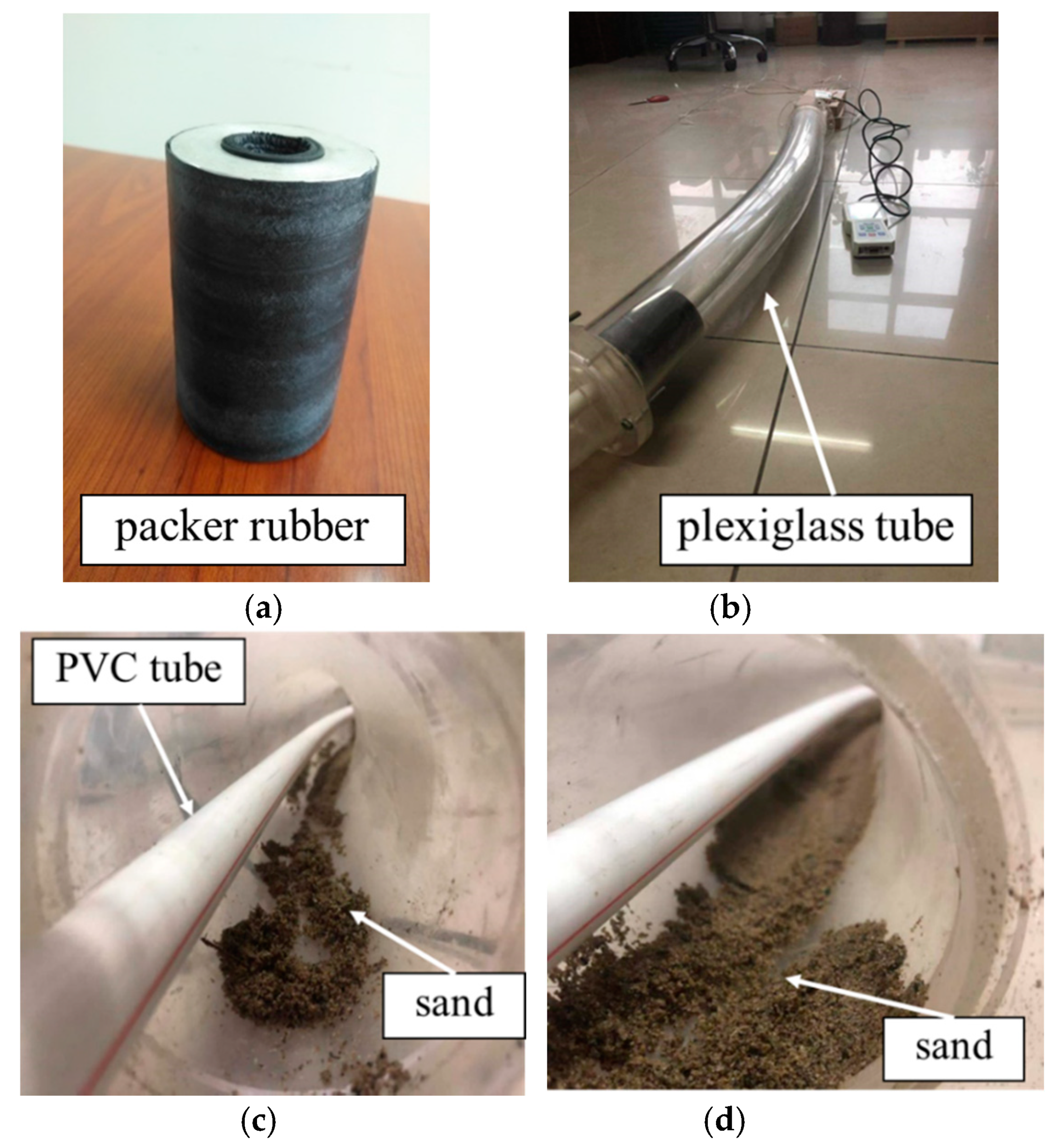
Figure 4.
Schemes of the packer in the horizontal hole: (a) The packer simulated by a cement column; (b) the packer in the horizontal hole simulated by a rubber cylinder; (c) the hole with little cuttings; and (d) the hole with lots of cuttings.
Figure 4.
Schemes of the packer in the horizontal hole: (a) The packer simulated by a cement column; (b) the packer in the horizontal hole simulated by a rubber cylinder; (c) the hole with little cuttings; and (d) the hole with lots of cuttings.

Figure 5.
Local drag results of the packer in the horizontal hole: (a) In the smooth horizontal section; and (b) in the horizontal section with microsteps.
Figure 5.
Local drag results of the packer in the horizontal hole: (a) In the smooth horizontal section; and (b) in the horizontal section with microsteps.

Figure 6.
Local drag results of the packer in the horizontal hole: (a) The hole with little cuttings; and (b) the hole with lots of cuttings.
Figure 6.
Local drag results of the packer in the horizontal hole: (a) The hole with little cuttings; and (b) the hole with lots of cuttings.

Figure 7.
Local drag results of the packer in the horizontal hole with microsteps and cuttings: (a) The hole with little cuttings; and (b) the hole with lots of cuttings.
Figure 7.
Local drag results of the packer in the horizontal hole with microsteps and cuttings: (a) The hole with little cuttings; and (b) the hole with lots of cuttings.
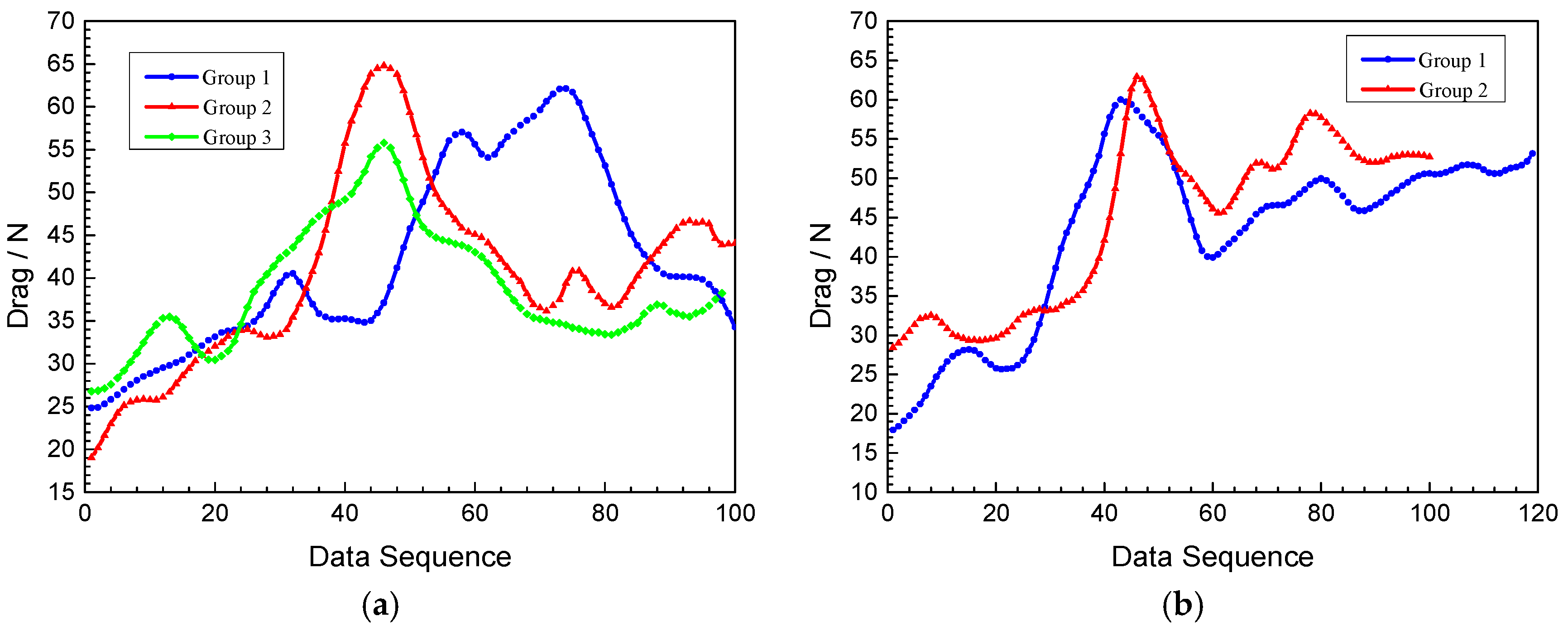
Figure 8.
Drag results of the completion string with a packer in the clean deviated section: (a) A typical drag curve of the whole moving process; and (b) stable sections of six groups of typical drag curves.
Figure 8.
Drag results of the completion string with a packer in the clean deviated section: (a) A typical drag curve of the whole moving process; and (b) stable sections of six groups of typical drag curves.

Figure 9.
Drag results of the completion string with a packer in the deviated section with a small amount of sand: (a) A typical drag curve of the whole moving process; and (b) six groups of drag section near the maximum value of the drag curve.
Figure 9.
Drag results of the completion string with a packer in the deviated section with a small amount of sand: (a) A typical drag curve of the whole moving process; and (b) six groups of drag section near the maximum value of the drag curve.
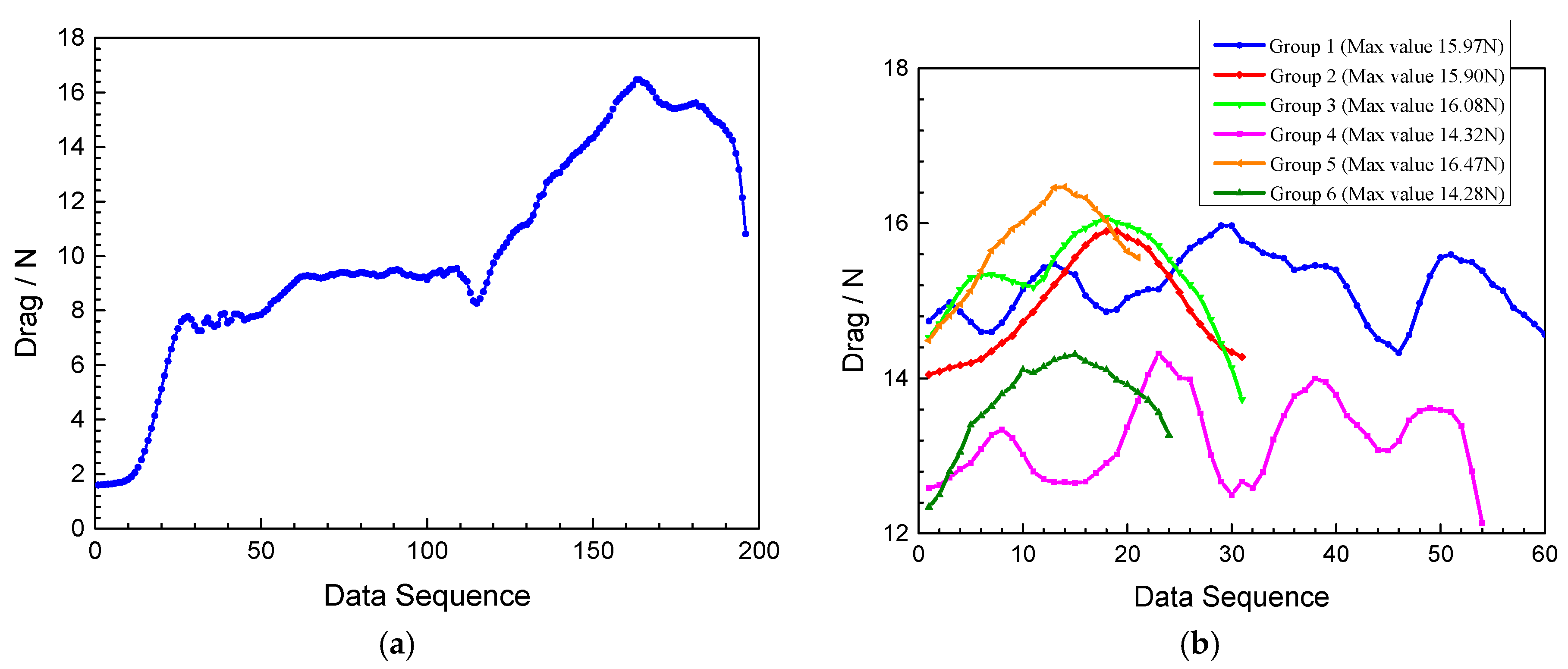
Figure 10.
Drag results of the completion string with a packer in the deviated section with lots of sand: (a) A typical drag curve of the whole moving process; and (b) six groups of drag section near the maximum value of the drag curve.
Figure 10.
Drag results of the completion string with a packer in the deviated section with lots of sand: (a) A typical drag curve of the whole moving process; and (b) six groups of drag section near the maximum value of the drag curve.
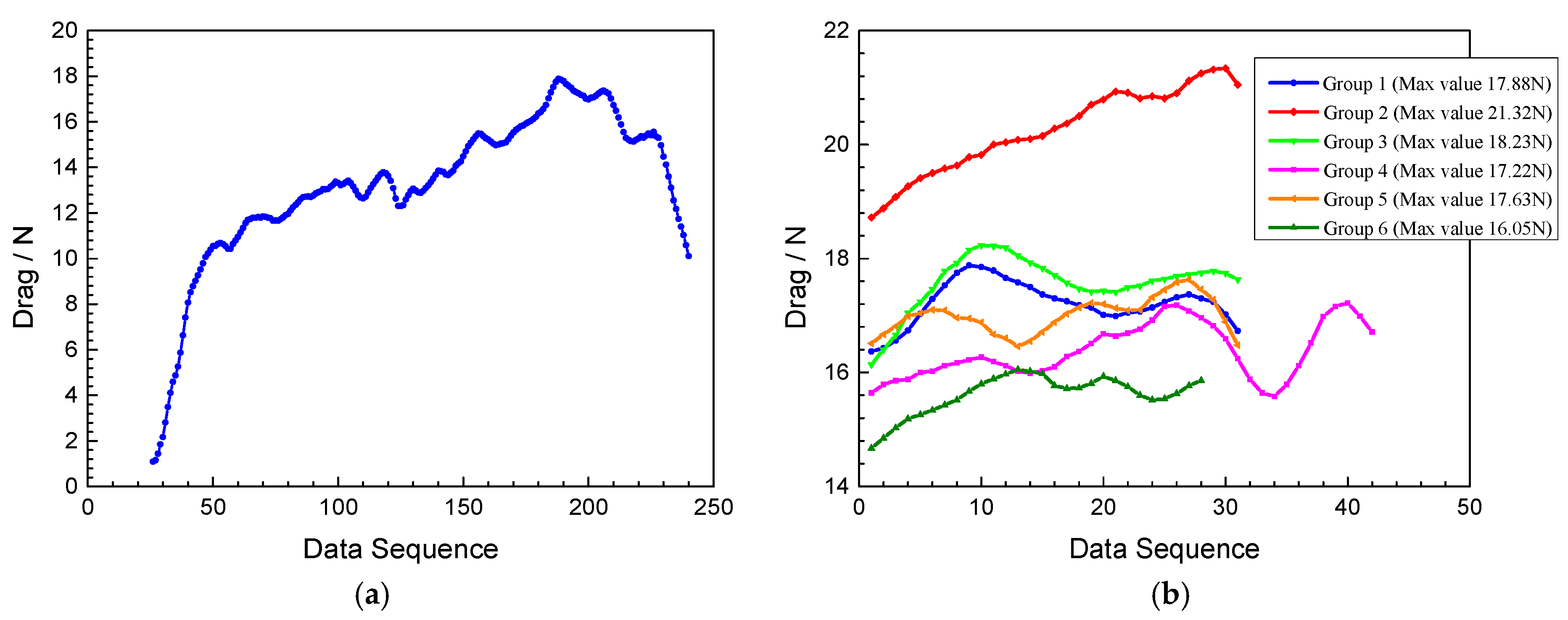
Figure 11.
Local drag test results of the cement column in the rubber cylinder: (a) A typical drag curve at the early test stage; and (b) typical drag curves at the stable stage.
Figure 11.
Local drag test results of the cement column in the rubber cylinder: (a) A typical drag curve at the early test stage; and (b) typical drag curves at the stable stage.
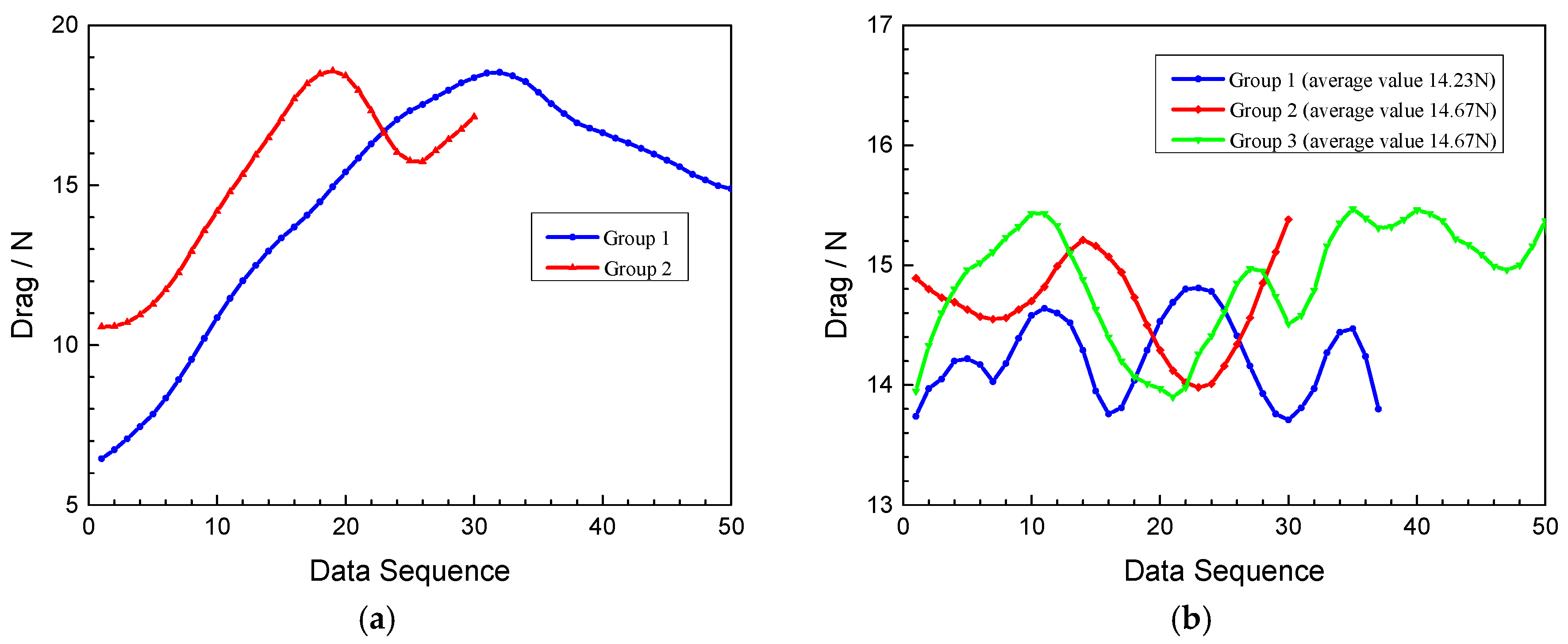
Figure 12.
Local drag test results of the cement column in the rubber cylinder with sand: (a) Little sand; (b) more sand; (c) a large amount of sand; and (d) huge amounts of sand.
Figure 12.
Local drag test results of the cement column in the rubber cylinder with sand: (a) Little sand; (b) more sand; (c) a large amount of sand; and (d) huge amounts of sand.
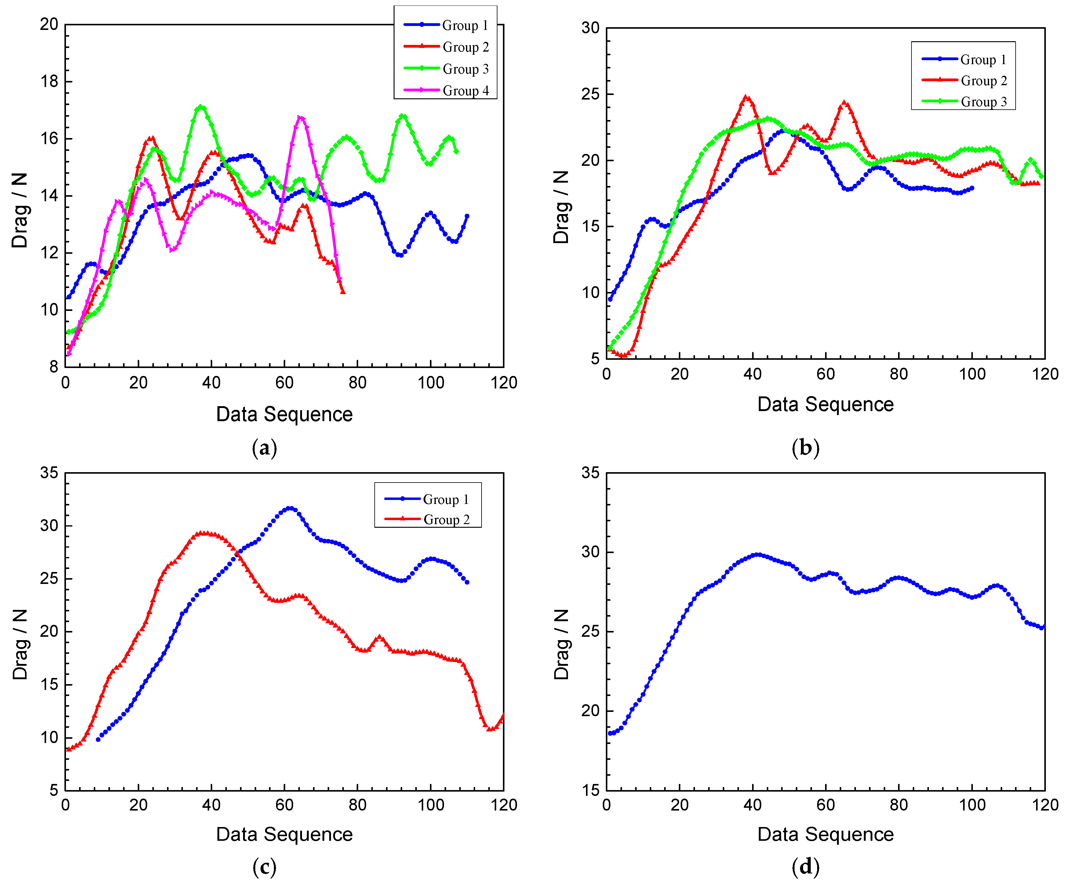
Figure 13.
Local typical drag curves of the cement column in the hard plastic cylinder: (a) The hard plastic cylinder has no sand particles; (b) the hard plastic cylinder has little sand particles; and (c) the hard plastic cylinder has lots of sand particles.
Figure 13.
Local typical drag curves of the cement column in the hard plastic cylinder: (a) The hard plastic cylinder has no sand particles; (b) the hard plastic cylinder has little sand particles; and (c) the hard plastic cylinder has lots of sand particles.


© 2020 by the authors. Licensee MDPI, Basel, Switzerland. This article is an open access article distributed under the terms and conditions of the Creative Commons Attribution (CC BY) license (http://creativecommons.org/licenses/by/4.0/).
Share and Cite
MDPI and ACS Style
Liang, Q.; Xia, B.; Liu, B.; Nie, Z.; Gao, B. Experimental Study on the Local Drag of Completion String with Packers in Horizontal Wells. Coatings 2020, 10, 657. https://doi.org/10.3390/coatings10070657
AMA Style
Liang Q, Xia B, Liu B, Nie Z, Gao B. Experimental Study on the Local Drag of Completion String with Packers in Horizontal Wells. Coatings. 2020; 10(7):657. https://doi.org/10.3390/coatings10070657
Chicago/Turabian StyleLiang, Qimin, Bairu Xia, Baolin Liu, Zhen Nie, and Baokui Gao. 2020. "Experimental Study on the Local Drag of Completion String with Packers in Horizontal Wells" Coatings 10, no. 7: 657. https://doi.org/10.3390/coatings10070657
Note that from the first issue of 2016, this journal uses article numbers instead of page numbers. See further details here.