
Ce and Y Co-Doping Effects for (Ba0.85Ca0.15)(Zr0.1Ti0.9)O3 Lead-Free Ceramics

1
Department of Intelligent Energy and Industry, Chung-Ang University, Seoul 06974, Korea
2
School of Electrical and Electronics Engineering, Chung-Ang University, Seoul 06974, Korea
*
Author to whom correspondence should be addressed.
Coatings 2021, 11(10), 1248; https://doi.org/10.3390/coatings11101248
Submission received: 7 September 2021
/
Revised: 9 October 2021
/
Accepted: 9 October 2021
/
Published: 14 October 2021
(This article belongs to the Special Issue Thin Films for Electronic Devices)
Abstract
:CeO2 and Y2O3 were co-doped to (Ba0.85Ca0.15)(Zr0.1Ti0.9)O3 ceramics and sintered by conventional solid-state reaction process to form x wt.% CeO2-y wt.% Y2O3 doped (Ba0.85Ca0.15)(Zr0.1Ti0.9)O3 (CexYy-BCZT) ceramics. The effects of different contents of CeO2-Y2O3 dopants to the (Ba0.85Ca0.15) (Zr0.1Ti0.9)O3 composition were analyzed by studying the phase, surface microstructure, piezoelectric and ferroelectric properties of BCZT ceramics. In this study, we have shown that co-doping a small amount of CeO2 and Y2O3 will not change the phase structure of (Ba0.85Ca0.15)(Zr0.1Ti0.9)O3 ceramics. However, the proper introduction of CeO2 and Y2O3 can improve the piezoelectric constant and electromechanical coupling coefficient of BCZT ceramic samples. Moreover, these dopants can promote the grain growth process in (Ba0.85Ca0.15) (Zr0.1Ti0.9)O3 ceramics. C0.04Y0.02 doped (Ba0.85Ca0.15)(Zr0.1Ti0.9)O3 ceramic has the best piezoelectric properties compared with other composition, the results are as follows: Relative density = 96.9%, Kp = 0.583, and d33 = 678 pC/N, V = 8.9 V. It means that this Ce0.04Y0.02 doped (Ba0.85Ca0.15)(Zr0.1Ti0.9)O3 ceramic is a desired material in the application of lead-free ceramics.
1. Introduction
In the past few decades, lead zirconate titanate (PZT) ceramics have been widely employed in piezoelectric device applications due to their high piezoelectric charge coefficient (d33 = 220–590 pC/N), electromechanical coupling coefficient (kp = 0.5–0.7), and high Curie temperature (Tc = 550 °C. However, these attractive PZT ceramics have some kinds of drawbacks in volatile and toxic properties [1,2]. During the sintering process, it will volatilize quickly if the temperature exceeds 880 °C, which creates defects in the structure. Therefore, electrical properties can be degenerated due to stoichiometric imbalance. In addition, to overcome toxic and related environmental problems, many attempts have been made. Among these attempts, research on lead-free materials has been increased. In order to achieve the goal of eco-friendly and sustainable development for piezoelectric materials, the new development of lead-free ceramics and PVDF piezoelectric film with excellent performance is essential for human beings [3,4,5,6,7,8]. PVDF piezoelectric film also has high chemical stability, soft texture, and lightweight merits [9].
As lead-free piezoelectric ceramics, (Ba0.85Ca0.15)(Zr0.1Ti0.9)O3 ((hereafter BCZT)) ceramics have strong merits in the piezoelectric device applications due to their high piezoelectric charge coefficient of 600 pC/N and electro-mechanical coupling coefficient of 0.5 [10,11]. One of the family materials of BaTiO3 piezoelectric ceramics, BCZT ceramics, have substituted components of Ca and Zr for A and B site of the perovskite structure. Due to the substituted materials of Ca and Zr in the perovskite structure, partial strains were developed in the lattice parameters of substituted BCZT ceramics. Due to this controlled strain in the perovskite structure, piezoelectric properties can be increased. Since there are no volatile elements in the BCZT composition, BCZT can well maintain the pre-designed stoichiometric composition even after a high sintering temperature process. Especially, BCZT has an environmentally friendly composition and has a large relative dielectric constant, high residual polarization strength, low dielectric loss, and piezoelectric performance comparable to PZT-based ceramics. Therefore, it is one of the most promising lead-free piezoelectric ceramic systems to replace lead-containing materials [12,13,14]. The core performance of piezoelectric ceramics is the piezoelectric charge coefficient and electromechanical coupling coefficient. Having excellent piezoelectric charge coefficient and electromechanical coupling coefficient can make piezoelectric materials for good energy harvesting devices with high performance. Researchers have made many efforts to improve the piezoelectric properties of BCZT ceramics. For example, Wang et al. studied the effects of various rare earth elements on the piezoelectric properties of BCZT ceramics, and the increased piezoelectric properties ranged from 475 to 521 pC/N [15]. Generally, to maintain electrical neutrality, donor doping will form a certain amount of cation vacancies in the BCZT lattice. These cation vacancies will promote the movement of the electric domain wall during the polarization process. Thus, that the number of domains oriented along the direction of the electric field increases, thereby increasing Piezoelectric properties of piezoelectric ceramics, electromechanical coupling coefficient. Therefore, the purpose of this research is to co-doped two kinds of donor doping elements to obtain BCZT ceramics with dual donor doping effects and high-voltage electrical coefficients.
2. Materials and Methods
BaCO3 (purity 99%, High Purity Chemicals KOJUNDO CHEMICAL LABORATORY Co., Ltd., Chiyoda, Sakado, Japan), CaCO3 (purity 99.0%, Sigma-Aldrich Co., Ltd., St. Louis, MO, USA), TiO2 (purity 99.9%), ZrO2 (purity 99.0%), CeO2, Y2O3 are raw materials, and x wt.% CeO2 y wt.% Y2O3—(Ba0.85Ca0.15) (Ti0.9Zr0.1) O3—(CexYy-BCZT) ceramic powder is prepared by a conventional solid-state reaction method. These starting powders were weighed according to the stoichiometric ratio and then ball milled with ethanol and zirconia balls for 24 h. After drying for 12 h at 120 °C, the mixture was calcined at 1300 °C for 2 h. Subsequently, these powders were mixed with polyvinyl alcohol (PVA) as a binder and pressed into a (12 mm × 1.2 mm). The thick films were prepared by the milling process. The thickness of thick films was measured and controlled by the vernier calipers. After the PVA was burned, it was sintered at a temperature of 1450 to 1550 °C for 4 h. To characterize its dielectric and piezoelectric properties, the sample was screen printed with silver paste on the top and bottom and cured at 700 °C for 10 min. Polarize these samples in silicone oil at 30 °C and 30–40 kV/cm for 20 min. X-ray diffraction (XRD, D8-Advance/Bruker-AXS, Karlsruhe, Germany) was used to study and analyze the crystal structure. The piezoelectric constant d33 was determined by the Berlin court type quasi-static meter. The cross-section of the sample was etched at a temperature 150 °C lower than the sintering temperature of the sample for 60 min. Observe the microstructure of the sample by scanning electron microscope (FE-SEM, SIGMA 300, Carl Zeiss, Jena, Germany). When observing the microstructure of the sample in the FE-SEM system, the operating conditions were as follows, magnification: 1000 or 5000 times, working distance: 6.8 mm, acceleration voltage: 5.00 KV, image resolution pixel: 1024 × 768 pixels. Through measurement and calculation, the volume density and relative density were obtained.
3. Result and Discussion
In order to study the influence of different sintering temperatures on Ce0.04Y0.02-BCZT ceramics, XRD measurements were performed at the sintering temperature between 1450 and 1550 °C.
Figure 1 shows the sintering temperature dependent X-ray diffraction patterns of Ce0.04Y0.02-BCZT ceramics. It was observed that the peaks position of Ce0.04Y0.02-BCZT ceramics have perovskite structure without any pyrochlore phase. This indicates that co-dopants of Ce and Y diffuse into the BCZT ceramic lattice without destroying the original crystal structure and forming a solid solution [16]. As shown in Figure 1, the reflection of (211) peaks moved to the lower angle as the sintering temperature increased. This means that unit cell volume was increased as the sintering temperature increased. However, the sintering temperature rises from 1500 to 1550 °C, reflection of (211) peaks almost no movement. This shows that, compared to other sintering temperatures, 1500 °C was the most helpful for ion substitution and solid solution formation, thus it reached the maximum at 1500 °C.
Figure 2 shows the sintering temperature-dependent piezoelectric charge coefficient of d33 and electromechanical coupling coefficient of kp for Ce0.04Y0.02-BCZT ceramics. The sintering temperature-dependent properties of d33 and Kp showed similar behavior to each other. First, as the sintering temperature increased, the d33 and kp of Ce0.04Y0.02-BCZT ceramics increased from 620 pC/N and 0.535 to 678 pC/N and 0.583 at 1450 °C and 1500 °C, respectively. Then, when the temperature reached 1550 °C, the piezoelectric performance and electromechanical coupling coefficient of Ce0.04Y0.02-BCZT ceramics began to decrease. This sintering temperature-dependent behavior of d33 and kp can be explained by the principle of ceramic sintering. The main purpose of the sintering process was to promote the full growth of ceramic grains [17]. During the sintering process, grain size became larger with reducing the porosity. However, when the sintering temperature reached 1550 °C, over sintering process began to start. Many grains grow abnormally without stoichiometric composition due to the excessively high sintering temperature. Therefore, grain distribution became irregular, resulting in many defects and reduced density. Therefore, the piezoelectric properties and electromechanical coupling coefficient of ceramics deteriorate when the sintering temperature was 1550 °C. Based on Figure 2, it seems that the best piezoelectric properties of Ce0.04Y0.02-BCZT ceramics were when the sintering temperature was around 1500 °C. Therefore, based on this result, co-doping effects of Ce and Y to BCZT were analyzed at the sintering temperature near 1500 °C.
Figure 3a,b show the X-ray diffraction patterns of Ce0.04Yy doped BCZT ceramic, and CexY0.02 doped BCZT ceramics, respectively. Both ceramic specimens were sintered at 1500 °C with different CeO2-Y2O3 contents. As shown in Figure 3, all synthesized CeY doped BCZT ceramics showed a pure perovskite structure without any pyrochlore phase. This means that Ce4+ and Y3+ cations diffused into the BCZT lattice to form a complete solid solution. As shown in Figure 3a, as the content of Y2O3 increases, the diffraction peaks of CeO2 and Y2O3 doped BCZT ceramics shift slightly to a higher angle. The reason for this phenomenon was the tolerance factor and radius matching rule. This can be explained from the following relational expression [18,19].
where Ra is radius of A site, Rb is radius of B site, Ro is the oxygen ion, and t is the tolerance factor [20]. If t = 1, it means it has a cube structure. However, if t is not 1, it means that it has a certain disordered structure. As it deviates from 1, the degree of distortion increases, which has been shown to affect the stability of the ABO3 structure. Generally, it is reported that, when t > 0.8, a stable ABO3 structure can be formed [21]. The tolerance factor ta is for the substitution of doped ions for the A site, and the tolerance factor tb is for substitution of the doped ions for the B site, respectively. When the difference between ta and tb is less than 0.02, it is considered that the doped ions may enter the A site and the B site at the same time. Therefore, we may argue that small ion [r(R3+) < 0.087 nm] will enter the B position, and the large ion [r(R3+) > 0.094 nm] will enter the A position. As a result, Y3+ (r = 0.09 nm) may enter the A site, or it may enter the B position. As shown in Figure 3c, by comparing BCZT and Ce doped BCZT ceramics, (002) and (200) peaks of Ce doped BCZT ceramics moved to the low angle. It means that lattice parameter c was increased. This increased lattice parameter indicates that the Ce ion in the BCZT-Ce0.04 ceramic tends to occupy the B site. The reflection peaks of (002) and (200) in Ce0.04Yy-BCZT ceramic moved to a higher angle with the increase of y doping, and it can be known that Y3+ in the Ce0.04Yy-BCZT ceramic tends to enter the A position. As shown in Figure 3d, compared with BCZT ceramics, the reflection peak of (110) in BCZT-Y0.02 ceramic moves to a higher angle as Y doping process. It means that lattice parameter a was decreased as increasing Y dopant. This decreased lattice parameter a indicates that the Y ion in the BCZT-Y0.02 ceramic tends to occupy the A site, the same as when co-doping. By comparing BCZT-Y0.02 and BCZT-C0.02 Y0.02 ceramics, the reflection of (110) of BCZT-Ce0.02 Y0.02 ceramic moves to a higher angle and then moves to a lower angle as the content of Ce increases. It means that with the increase of Ce ions during co-doping, it first enters the A site and then enters the B site. It is somewhat different from the Ce ion occupying a place in BCZT-Ce ceramics. Since Ce ions have two valence states (Ce3+ (0.134 nm) and Ce4+ (0.087 nm)), according to the radius matching rule, large ions tend to replace large ions, and small ions tend to replace small ions. The Ti4+ (0.060 nm) and Zr4+ (0.072 nm) ions at the B site have a small radius, thus Ce4+ ions enter the B site, which is equivalent doping, no electronic gains, and losses, and Ce3+ ions enter the A site, which is the donor doping. Therefore, the co-doping of Ce and Y in CexYy-BCZT ceramics can be regarded as double-donor doping. Moreover, in the co-doping process, Ce3+ ions are produced first, and then Ce4+ ions are produced.
Figure 4 display the measured density of Ce and Y doped BCZT ceramics. Figure 4a shows the bulk density of Ce0.04Yy doped BCZT ceramics, which Y2O3 contents was varied from 0.02 to 0.06, while Figure 4b displays CexY0.02 doped BCZT ceramics, which Ce was varied from 0.02 to 0.06, respectively. It seems that the density of Ce and Y doped BCZT ceramics was related to the doped content.
The density of ceramics is closely related to the pores and grain size [22]. It can be seen from Figure 5a,b of SEM that when the ceramic is only doped with Ce and only with Y alone, the grain size was reduced, while the density was increased due to the reduction of pores. When ceramics were co-doped, as the number of doping increases, the crystal grains gradually became larger, and the pores gradually decreased. The density of Ce0.04Y0.02-BCZT ceramics was 5.63 g/cm3, which corresponds to 96.9% of the theoretical density of BCZT ceramics of 5.81 g/cm3 [23]. Figure 5c,d shows that when doped excessively, the grains grow abnormally, the holes increase, and the crystal grains decrease. The increase in relative density should be due to the increase in grain size and the decrease in porosity. However, when over-doped, the density will decrease. Although the grain size of Ce doped BCZT and Y doped BCZT ceramics have been reduced, the density has increased. This was the same as other reports that only doped Y or only Ce. We generally believe that rare-earth ions have an inhibitory effect on grain growth in perovskites because of their low diffusion rate [24]. When Ce = 0.04 wt.% Y = 0.02 wt.%, the grain size of the sample was more uniform than that of the sample without doping, the grain distribution was more regular, and the existence of pores was also reduced. This shows that the appropriate amount of co-doping Ce-Y was helpful for grain growth. In general, the difficulty of domain movement in piezoelectric ceramics affects the piezoelectric performance. There is a great relationship between the turning of the electric domain and the growth of the crystal grains [25,26]. When excessive doping, crystal grain grows abnormally, the pores become larger, and the number of pores increases, small crystal grains are mixed between large crystal grains, and the crystal grains are squeezed and deformed, which also affects the domain wall motion [27]. The electrical properties of the sample deteriorate.
When Ce and Y dual donors were co-doped, cation vacancies were generated to maintain electrical neutrality, and cation vacancies promoted the turning of the electrical domain wall. Therefore, co-doping can increase the piezoelectric properties of ceramics, but excessive doping of Ce and Y will cause CeO2 and Y2O3 to precipitate at the grain boundaries, refine the grains, produce pores [28], thus reducing the piezoelectric properties of the ceramic.
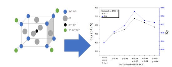
Figure 6 display piezoelectric charge coefficient and electro-mechanical coupling coefficient of the Ce and Y doped BCZT ceramics. (a) For the Ce0.04Yy doped BCZT ceramics, (b) CexY0.02 doped BCZT ceramics, respectively. As shown in Figure 6, the behavior d33 and kp were very similar. As increasing the dopant, the piezoelectric charge coefficient d33 and electro-mechanical coupling coefficient kp were increased. It decreased after reaching the maximum. When the Ce doping amount was 0.04 wt.% and the Y doping amount was 0.02 wt.%, the piezoelectricity of the sample the coefficient and kp reached the highest point, d33 = 678 pC/N, kp = 0.583. From Figure 6, we can see that the kp and d33 of co-doped ceramics were further improved compared with doping with only one element
It seems that dual donor doping effects were a more effective doping method for BCZT ceramics to have higher kp and d33 values. The electrical properties of piezoelectric ceramics were also closely related to the microstructure. From Figure 1 and Figure 3, we know that the interior of the ceramic was a state where orthorhombic and tetragonal phases coexisted, and when Ce = 0.04 wt.%, Y = 0.02 wt.%, the ceramic density is the highest. The grain size is also large and uniform, while the number of pores is increased with small size. This reduces the difficulty of domain turning. Therefore, Ce0.04Y0.02 doped BCZT ceramics showed the highest piezoelectric performance in this research.
Figure 7a,b shows the schematic diagrams of the piezoelectric energy harvesting system and their equivalent circuit for the piezoelectric ceramics, respectively. By operating the energy harvesting system by the controlling system, a pressure of 200 N was applied through the mechanical force system with 0.25 Hz. Oscilloscope was employed to record generated output voltages in BCZT-CY ceramic.
As shown in Figure 8, voltages meant that generated output voltages in the piezoelectric energy harvesters were made of (a) Ce0.04Yy doped BCZT ceramic and (b) CexY0.02 doped BCZT ceramics, respectively. The generated piezoelectric output voltage was important for energy harvesting, which represents the electrical energy generated by the ceramic when pressure was applied, which can be explained by the following formula.
g33 = d33/εrε0
V = (g33hT)
The g33 is the piezoelectric voltage constant, ε0 is the dielectric constant measured under vacuum conditions, εr is the dielectric constant of the ceramic in the air [29]. V is the voltage generated when pressure is applied to the ceramic, h is the ceramic thickness, and T is the stress [30]. As shown in Equations (2) and (3), generated output voltage can be controlled by the piezoelectric properties of g33, devices structural parameter of h, and applied stress of T, respectively. Figure 8 displays the open-circuit voltage generated by applying a force of 200 N in a 0.25 Hz environment, the open-circuit voltage measured by BCZT-Ce0.04Y0.02 ceramics was 8.9 V, the highest value among BCZT-CexYy ceramics. Figure 8 displays the behavior of the open-circuit voltage was very consistent with d33 in Figure 6, and it can be seen from formula (2) that the greater the value of d33, the greater the voltage generated when pressure was applied.
4. Conclusions
In this study, (Ba0.85Ca0.15)(Zr0.1Ti0.9) O3 ceramics with dual donor doping effects were prepared by co-doping Ce and Y. A small amount of CeY co-doping can significantly improve the performance of (Ba0.85Ca0.15)(Zr0.1Ti0.9)O3 ceramics. The effects of different contents of CeO2-Y2O3 dopants to the (Ba0.85Ca0.15)(Zr0.1Ti0.9)O3 composition were analyzed by studying the phase, surface microstructure, piezoelectric, and ferroelectric properties of BCZT ceramics. By optimizing the co-doping process of CeO2 and Y2O3 to (Ba0.85Ca0.15)(Zr0.1Ti0.9) O3 ceramics, piezoelectric and electro-mechanical properties were improved. Moreover, these dopants can promote the grain growth process in (Ba0.85Ca0.15)(Zr0.1Ti0.9) O3 ceramics. C0.04Y0.02 doped (Ba0.85Ca0.15)(Zr0.1Ti0.9)O3 ceramic showed the highest piezoelectric properties compared with other composition, the results were as follows: relative density = 96.9%, Kp = 0.583, and d33 = 678 pC/N, V = 8.9 V. It means that this C0.04Y0.02 doped (Ba0.85Ca0.15)(Zr0.1Ti0.9)O3 ceramic was a desired material in the application of lead-free ceramics. Since (Ba0.85Ca0.15)(Zr0.1Ti0.9)O3 piezoelectric materials have excellent piezoelectric properties such as piezoelectric charge coefficient d33 of 678 pC/N with high density, divided ingredients of piezoelectric components can be applied for the flexible device applications. By connecting by the gride line, this divided ingredient of piezoelectric components can be applied for flexible device applications.
Author Contributions
Data curation, C.L.; formal analysis, C.L. and J.-H.K.; investigation, C.L.; project administration, J.-H.K.; validation, C.L.; writing—original draft C.L. and J.-S.B.; writing—review and editing, C.L. and J.-H.K. All authors have read and agreed to the published version of the manuscript.
Funding
This research was supported by the MSIT (Ministry of Science and ICT), Korea, under the ITRC (Information Technology Research Center) support program (IITP-2021-2020-0-01655) supervised by the IITP (Institute of Information and Communications Technology Planning and Evaluation) and supported by the Chung-Ang University Young Scientist Scholarship in 2020 (admission year).
Institutional Review Board Statement
Not applicable.
Informed Consent Statement
Not applicable.
Data Availability Statement
The data presented in this study are available on request from the corresponding author.
Conflicts of Interest
The authors declare no conflict of interest.
References
- Haertling, H.K. Ferroelectric ceramics: History and technology. J. Am. Ceram. Soc. 1999, 82, 797–818. [Google Scholar] [CrossRef]
- Panda, K.P. Review: Environmental friendly lead-free piezoelectric materials. J. Mater. Sci. 2009, 44, 5049–5062. [Google Scholar] [CrossRef] [Green Version]
- Rödel, J.; Jo, W.; Seifert, K.T.P.; Anton, E.M.; Granzow, T. Perspective on the development of lead-free piezoceramics. J. Am. Ceram. Soc. 2009, 92, 1153–1177. [Google Scholar] [CrossRef]
- Shrout, T.R.; Zhang, S.J. Lead-free piezoelectric ceramics: Alternatives for PZT? J. Electroceram. 2007, 19, 111–124. [Google Scholar] [CrossRef] [Green Version]
- Clementi, G.; Margueron, S.; Suarez, M.A.; Baron, T.; Dulmet, B.; Bartasyte, A. Piezoelectric and pyroelectric energy harvesting from lithium niobate films. J. Phys. Conf. Ser. 2019, 1407, 012039. [Google Scholar] [CrossRef]
- Kalimuldina, G.; Turdakyn, N.; Abay, I.; Medeubayev, A.; Nurpeissova, A.; Adair, D.; Bakenov, Z. A Review of Piezoelectric PVDF Film by electrospinning and its applications. Sensors 2020, 20, 5214. [Google Scholar] [CrossRef] [PubMed]
- Acosta, M.; Novak, N.; Rojas, V.; Patel, S.; Vaish, R.; Koruza, J.; Rossetti, G.A., Jr.; Rodel, J. BaTiO3-based piezoelectrics: Fundamentals, current status, and perspectives. Appl. Phys. Rev. 2017, 4, 041305. [Google Scholar] [CrossRef] [Green Version]
- Mariello, M.; Fachechi, L.; Guido, F.; Vittorio, M.D. Multifunctional sub-100 µm thickness flexible piezo/triboelectric hybrid water energy harvester based on biocompatible AlN and soft parylene C-PDMS-Ecoflex™. Nano Energy 2021, 83, 2211–2855. [Google Scholar] [CrossRef]
- Mariello, M.; Qualtieri, A.; Mele, G.; Vittorio, M.D. Metal-free multilayer hybrid peng based on soft electrospun/sprayed membranes with cardanol additive for harvesting energy from surgical face masks. ACS Appl. Mater. Interfaces 2021, 13, 20606–20621. [Google Scholar] [CrossRef]
- Cui, Y.R.; Yuan, C.L.; Liu, X.Y.; Zhao, X.Y.; Shan, X. Lead-free (Ba0.85Ca0.15)(Ti0.9Zr0.1)O3-Y2O3 ceramics with large piezoelectric coefficient obtained by low-temperature sintering. J. Mater. Sci. Mater. Electron. 2013, 24, 654–657. [Google Scholar] [CrossRef]
- Li, W.; Xu, Z.; Chu, R.; Fu, P.; Peng, A. Effect of Ho doping on piezoelectric properties of BCZT ceramics. Ceram. Int. 2012, 38, 4353–4355. [Google Scholar] [CrossRef]
- Liu, W.; Ren, X. Large Piezoelectric Effect in Pb-Free Ceramics. PRL 2009, 103, 257602. [Google Scholar] [CrossRef] [PubMed] [Green Version]
- Ji, X.; Wang, C.B.; Harumoto, T.; Zhang, S.; Tu, R.; She, Q.; Shi, J. Structure and electrical properties of BCZT ceramics derived from microwave-assisted sol–gel-hydrothermal synthesized powders. Sci. Rep. 2020, 10, 20352. [Google Scholar] [CrossRef] [PubMed]
- Parjansri, P.; Intatha, U.; Eitssayeam, S. Dielectric, ferroelectric and piezoelectric properties of Nb5+ doped BCZT ceramics. Mater. Res. Bull. 2015, 65, 61–67. [Google Scholar] [CrossRef]
- Wang, L.; Bai, W.; Zhao, X.; Ding, Y.; Wu, S.; Zheng, P.; Li, P.; Zhai, J. Influences of rare earth site engineering on piezo electric and electromechanical response of (Ba0.85Ca0.15) (Zr0.1Ti0.9) O3 lead-free ceramics. Mater. Electron. 2020, 31, 6560–6573. [Google Scholar] [CrossRef]
- Liu, X.; Chen, Z.; Fang, B.; Ding, J.; Zhao, X.; Xu, H.; Luo, H. Enhancing piezoelectric properties of BCZT ceramics by Sr and Sn co-doping. J. Alloy. Compd. 2015, 640, 128–133. [Google Scholar] [CrossRef]
- Rahaman, M.N. Ceramic Processing and Sintering, 2nd ed.; CRC Press: Boca Raton, FL, USA, 2003. [Google Scholar]
- Bijalwan, V.; Hughes, H.; Pooladvand, H.; Tofel, P.; Nan, B.; Holcmanc, V.; Bai, Y.; Buttona, T.W. The effect of sintering tem perature on the microstructure and functional properties of BCZT-xCeO2 lead free ceramics. Mater. Res. Bull. 2019, 114, 121–129. [Google Scholar] [CrossRef]
- Gao, D.; Kwok, K.W.; Lin, D.; Chan, H.L.W. Microstructure, electrical properties of CeO2-doped (K0.5Na0.5) NbO3 lead-free piezoelectric ceramic. J. Mater. Sci. 2009, 44, 2466–2470. [Google Scholar] [CrossRef]
- Tsur, Y.; Ddunbar, T.D.; Randall, C.A. Crystal and defect chemistry of rare earth cations in BaTiO3. J. Electroceram. 2001, 7, 25–34. [Google Scholar] [CrossRef]
- Liu, X.C.; Hong, R.Z.; Tian, C.S. Tolerance factor and the stability discussion of ABO3-type ilmenite. J. Mater. Sci. 2009, 20, 323–327. [Google Scholar] [CrossRef]
- Kang, S.J.L. Elsevier Sintering, Densification, Grain Growth and Microstructure; Butterworth-Heinemann Publication: Oxford, UK, 2005; pp. 89–135. [Google Scholar]
- Buatip, N.; Promsawat, N.; Pisitpipathsin, N.; Namsar, O.; Pawasri, P.; Ounsung, P.; Phabsimma, K.; Rattanachan, S.T.; Janphuang, P.; Projprapai, S. Investigation on electrical properties of BCZT ferroelectric ceramics prepared at various sintering condition. Integr. Ferroelectr. 2018, 187, 45–52. [Google Scholar] [CrossRef]
- Cui, Y.; Liu, X.; Jiang, M.; Zhao, X.; Shan, X.; Li, W.; Yuan, C.; Zhou, C. Lead-free (Ba0.85Ca0.15) (Ti0.9Zr0.1)O3–CeO2 ceramics with high piezoelectric coefficient obtained by low-temperature sintering. Ceram. Int. 2012, 38, 4761–4764. [Google Scholar] [CrossRef]
- Gunnar, P.; Khansur, N.H.; Webber, K.G.; Kungl, H.; Hoffmann, M.J.; Hinterstein, M. Grain size effects in donor doped lead zirconate titanate ceramics. J. Appl. Phys. 2020, 128, 214105. [Google Scholar]
- Ştefan, Ţ. Micro and Nanoscale Characterization of Three Dimensional Surfaces. Basics and Applications; Napoca Star Publishing House: Cluj-Napoca, Romania, 2015; pp. 21–27. [Google Scholar]
- Ghosh, D.; Sakata, A.; Carter, J.; Thomas, P.A.; Han, H.; Nino, J.C.; Jones, J.L. Domain wall displacement is the origin of superior permittivity and piezoelectricity in BaTiO3 at Intermediate grain sizes. Adv. Funct. Mater. 2014, 24, 885–896. [Google Scholar] [CrossRef] [Green Version]
- Du, G.; Wei, F.; Li, W.; Chen, N. Co-doping effects of A-site Y3+ and B-site Al3+ on the microstructures and dielectric properties of CaCu3Ti4O12 ceramics. J. Eur. Ceram. Soc. 2017, 37, 4653–4659. [Google Scholar] [CrossRef]
- Yan, X.-D.; Zheng, M.-P.; Zhu, M.; Hou, Y.-D. Soft and hard piezoelectric ceramics for vibration energy harvesting. Crystals 2020, 10, 907. [Google Scholar] [CrossRef]
- Shin, D.J.; Kim, J.-W.; Koh, J.H. Piezoelectric properties of (1-x)BZT-xBCT system for energy harvesting applications. J. Eur. Ceram. Soc. 2018, 38, 4395–4403. [Google Scholar] [CrossRef]
Figure 1.
Sintering temperature-dependent X-ray diffraction patterns of Ba0.85Ca0.15)(Zr0.1Ti0.9)O3-Ce0.04Y0.02 ceramics. The insert is a peak shift of (211) for different sintering temperatures from 1450 to 1550 °C.
Figure 1.
Sintering temperature-dependent X-ray diffraction patterns of Ba0.85Ca0.15)(Zr0.1Ti0.9)O3-Ce0.04Y0.02 ceramics. The insert is a peak shift of (211) for different sintering temperatures from 1450 to 1550 °C.

Figure 2.
Sintering temperature dependent piezoelectric charge coefficient of d33 and electro-mechanical coupling coefficient of kp of Ce0.04Y0.02-(Ba0.85Ca0.15)(Zr0.1Ti0.9)O3 ceramics.
Figure 2.
Sintering temperature dependent piezoelectric charge coefficient of d33 and electro-mechanical coupling coefficient of kp of Ce0.04Y0.02-(Ba0.85Ca0.15)(Zr0.1Ti0.9)O3 ceramics.

Figure 3.
(a) X-ray diffraction patterns of the Ce0.04Yy doped BCZT ceramics. (b) X-ray diffraction patterns of the CexY0.02 doped BCZT ceramics and (c) X-ray diffraction patterns of the Ce0.04Yy doped BCZT ceramics enlarge patterns near 40–50°. (d) X-ray diffraction patterns of the CexY0.02 doped BCZT ceramics enlarge patterns near 30–35°.


Figure 4.
The density of Ce and Y doped BCZT ceramics. (a) for the Ce0.04Yy doped BCZT ceramics, (b) CexY0.02 doped BCZT ceramics, respectively.
Figure 4.
The density of Ce and Y doped BCZT ceramics. (a) for the Ce0.04Yy doped BCZT ceramics, (b) CexY0.02 doped BCZT ceramics, respectively.

Figure 5.
The measured grain size of Ce and Y doped BCZT ceramics from the SEM images. (a) for the Ce0.04Yy doped BCZT ceramics, (b) CexY0.02 doped BCZT ceramics, (c) Ce0.04Yy doped BCZT ceramics grain size, (d) CexY0.02 doped BCZT ceramics grain size.
Figure 5.
The measured grain size of Ce and Y doped BCZT ceramics from the SEM images. (a) for the Ce0.04Yy doped BCZT ceramics, (b) CexY0.02 doped BCZT ceramics, (c) Ce0.04Yy doped BCZT ceramics grain size, (d) CexY0.02 doped BCZT ceramics grain size.


Figure 6.
Display piezoelectric charge coefficient and electro-mechanical coupling coefficient of the Ce and Y doped BCZT ceramics. (a) For the Ce0.04Yy doped BCZT ceramics, (b) CexY0.02 doped BCZT ceramics, respectively.
Figure 6.
Display piezoelectric charge coefficient and electro-mechanical coupling coefficient of the Ce and Y doped BCZT ceramics. (a) For the Ce0.04Yy doped BCZT ceramics, (b) CexY0.02 doped BCZT ceramics, respectively.

Figure 7.
(a)The schematic diagram of the piezoelectric energy harvesting system. (b) Detailed equivalent images of piezoelectric source part in (a).
Figure 7.
(a)The schematic diagram of the piezoelectric energy harvesting system. (b) Detailed equivalent images of piezoelectric source part in (a).

Figure 8.
Generated output voltage in the BCZT-CY ceramics ceramic after applying a pressure of 200 N. (a) For the Ce0.04 Yy doped BCZT ceramics, (b) CexY0.02 doped BCZT ceramics, respectively.
Figure 8.
Generated output voltage in the BCZT-CY ceramics ceramic after applying a pressure of 200 N. (a) For the Ce0.04 Yy doped BCZT ceramics, (b) CexY0.02 doped BCZT ceramics, respectively.

Publisher’s Note: MDPI stays neutral with regard to jurisdictional claims in published maps and institutional affiliations. |
© 2021 by the authors. Licensee MDPI, Basel, Switzerland. This article is an open access article distributed under the terms and conditions of the Creative Commons Attribution (CC BY) license (https://creativecommons.org/licenses/by/4.0/).
Share and Cite
MDPI and ACS Style
Li, C.; Baek, J.-S.; Koh, J.-H. Ce and Y Co-Doping Effects for (Ba0.85Ca0.15)(Zr0.1Ti0.9)O3 Lead-Free Ceramics. Coatings 2021, 11, 1248. https://doi.org/10.3390/coatings11101248
AMA Style
Li C, Baek J-S, Koh J-H. Ce and Y Co-Doping Effects for (Ba0.85Ca0.15)(Zr0.1Ti0.9)O3 Lead-Free Ceramics. Coatings. 2021; 11(10):1248. https://doi.org/10.3390/coatings11101248
Chicago/Turabian StyleLi, Chao, Jin-Su Baek, and Jung-Hyuk Koh. 2021. "Ce and Y Co-Doping Effects for (Ba0.85Ca0.15)(Zr0.1Ti0.9)O3 Lead-Free Ceramics" Coatings 11, no. 10: 1248. https://doi.org/10.3390/coatings11101248
Note that from the first issue of 2016, this journal uses article numbers instead of page numbers. See further details here.