
High-Efficient Gas Nitridation of AISI 316L Austenitic Stainless Steel by a Novel Critical Temperature Nitriding Process

 ,
,
Abstract
:1. Introduction
2. Experimental and Calculation Details
2.1. Sample Preparation
2.2. Gas Nitriding
2.3. Characterizations
2.4. First Principles Calculations
3. Results and Discussions
3.1. Microstructures of Conventional Gas Nitrided Layer of AISI 316L ASS
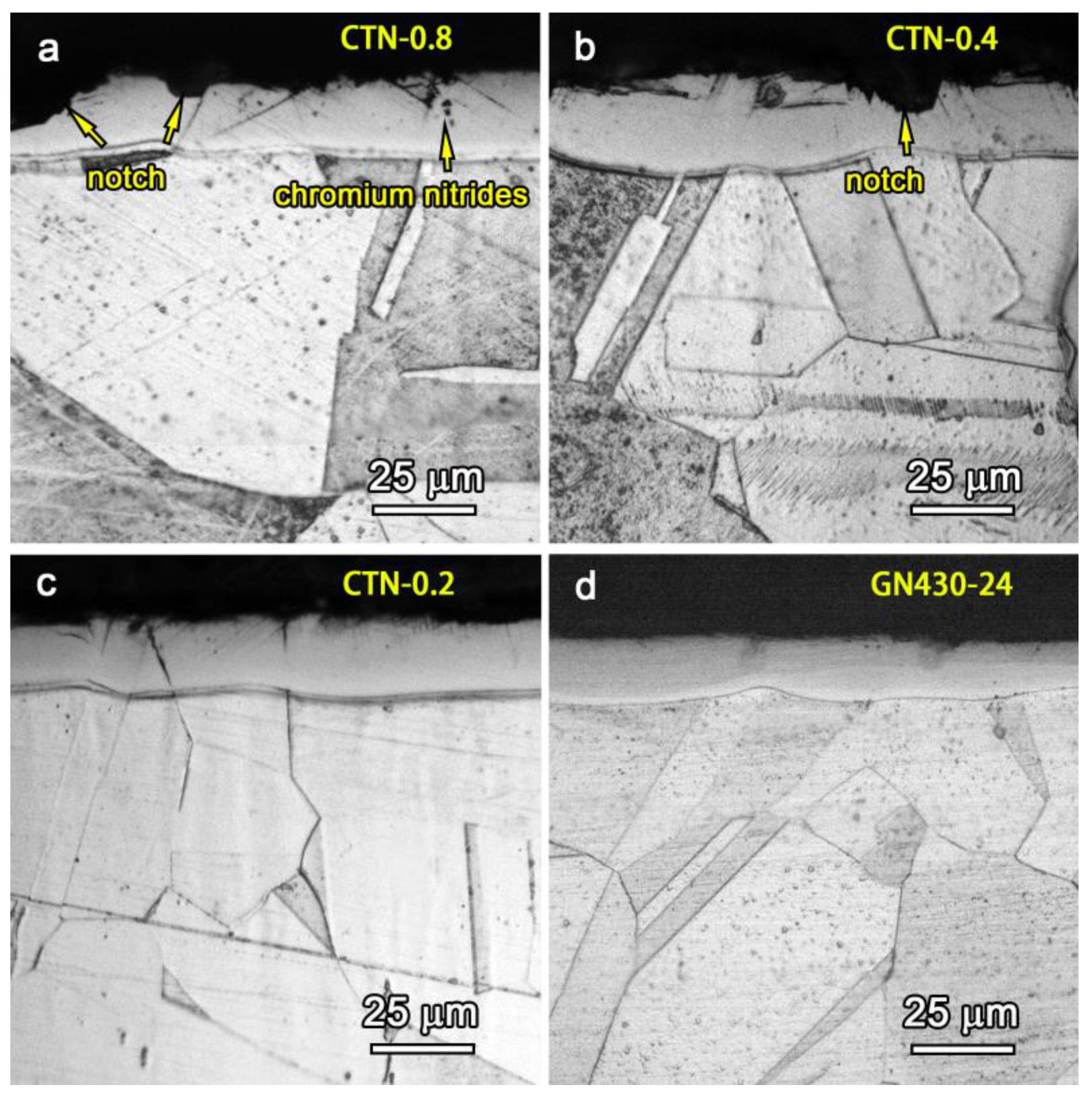
3.2. Microstructures of Critical Temperature Nitrided Layers
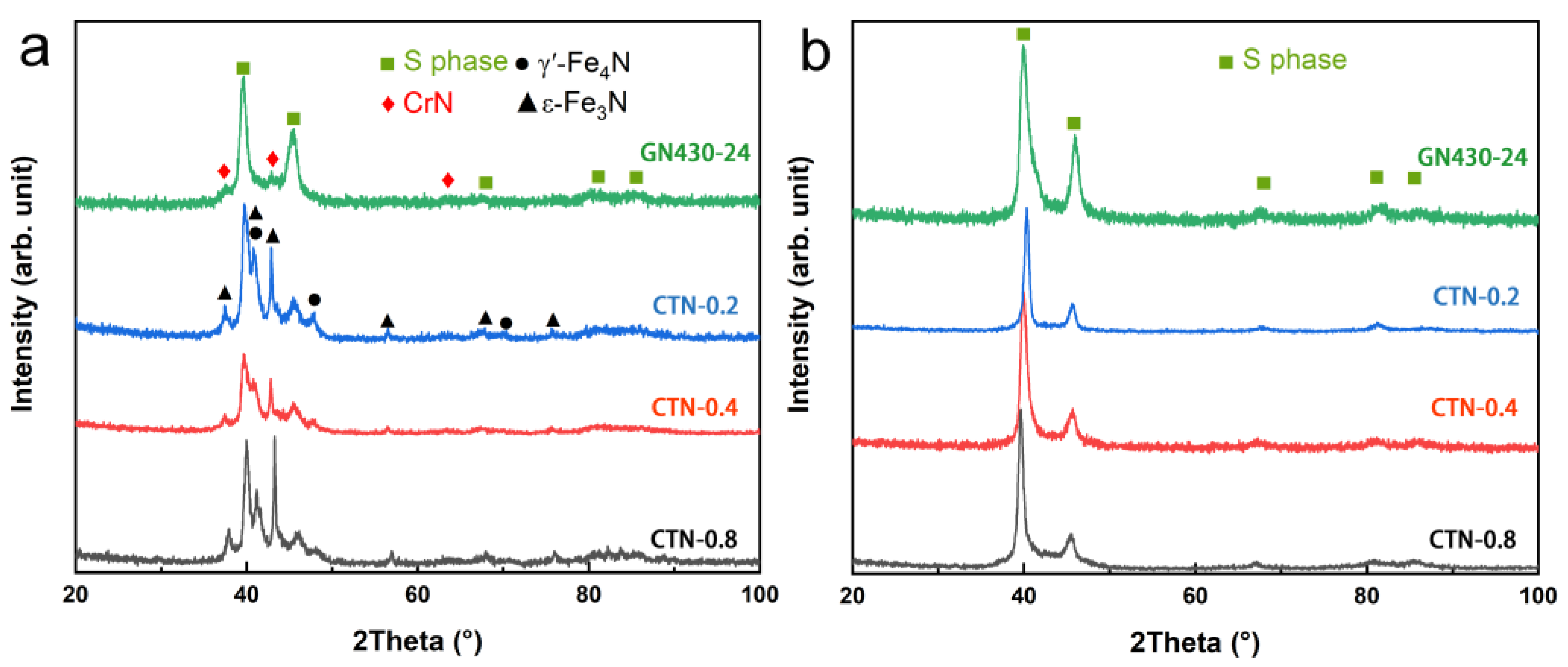
3.3. Phase Compositions of Critical Temperature Nitrided Layers
3.4. Nitridation Efficiency of Critical Temperature Nitriding Processes
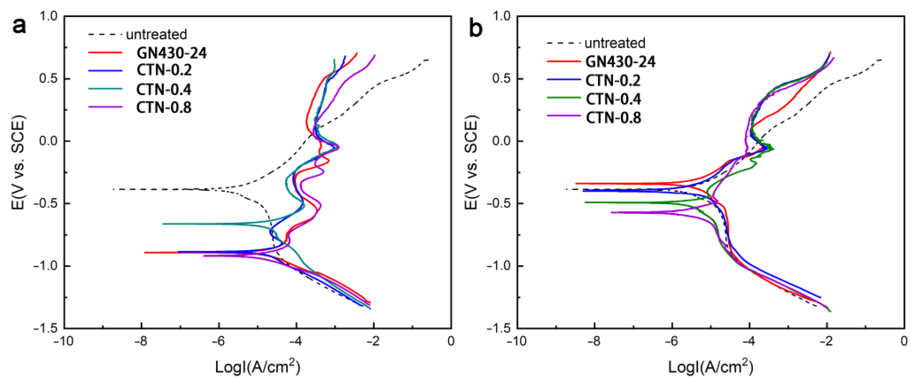
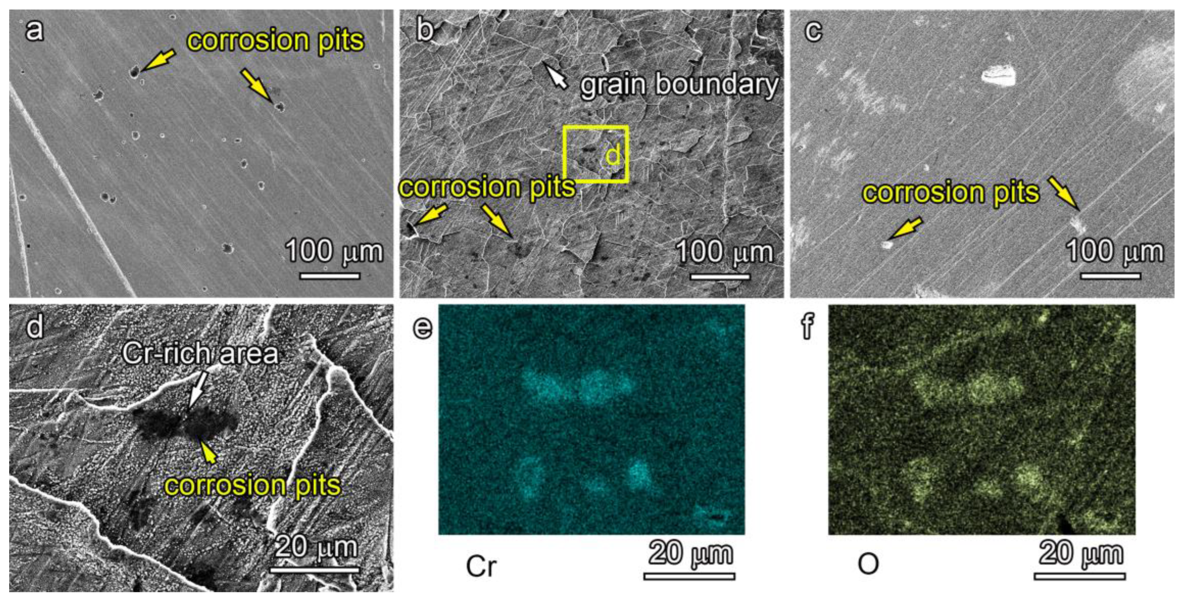
3.5. Corrosion Resistance of Critical Nitrided Layers
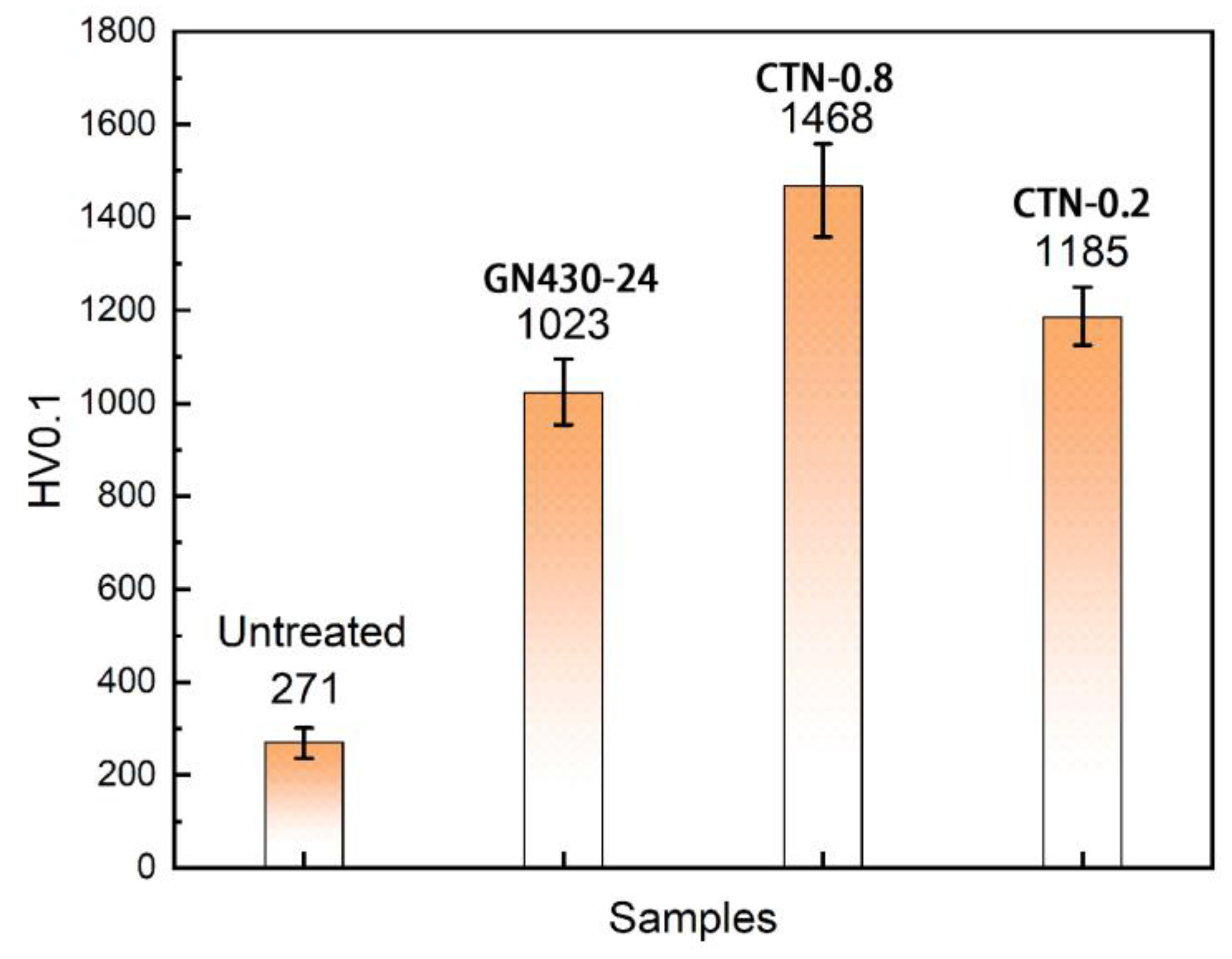
3.6. Wear Resistance of Critical Temperature Nitrided Layers
4. Discussion
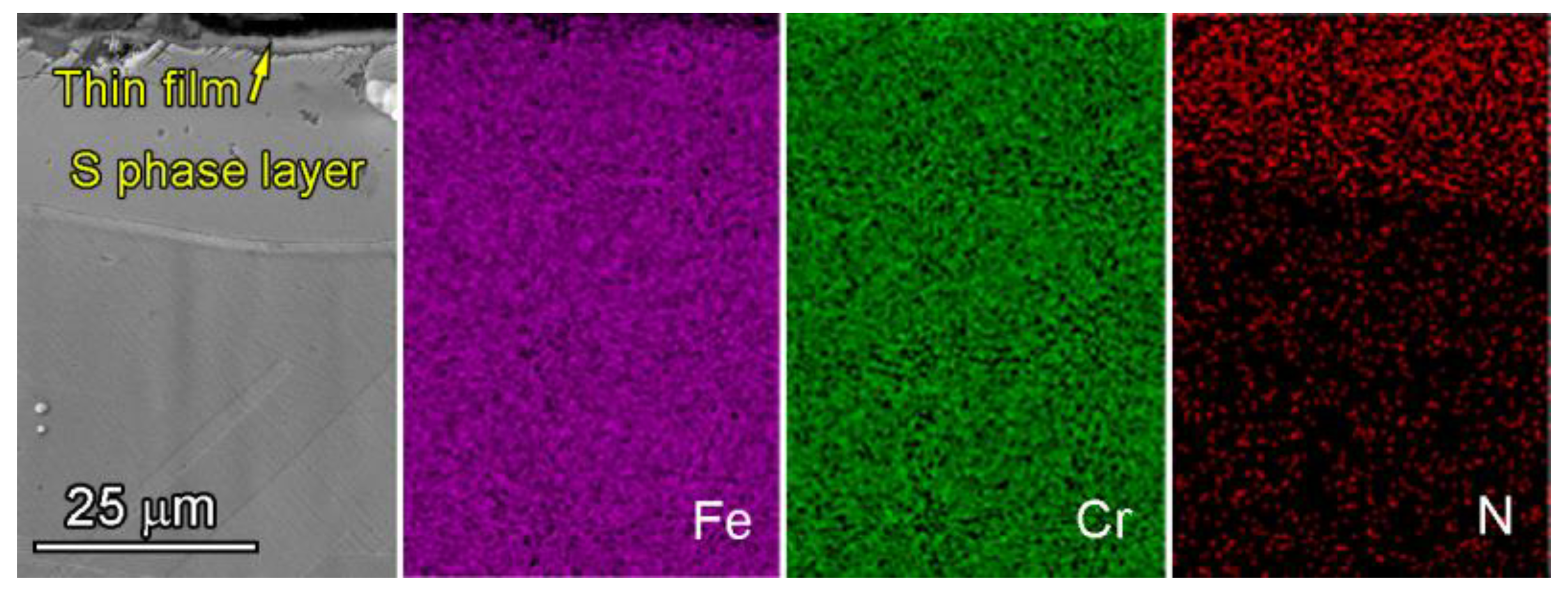
4.1. Distribution of Chromium in Nitrided Layers
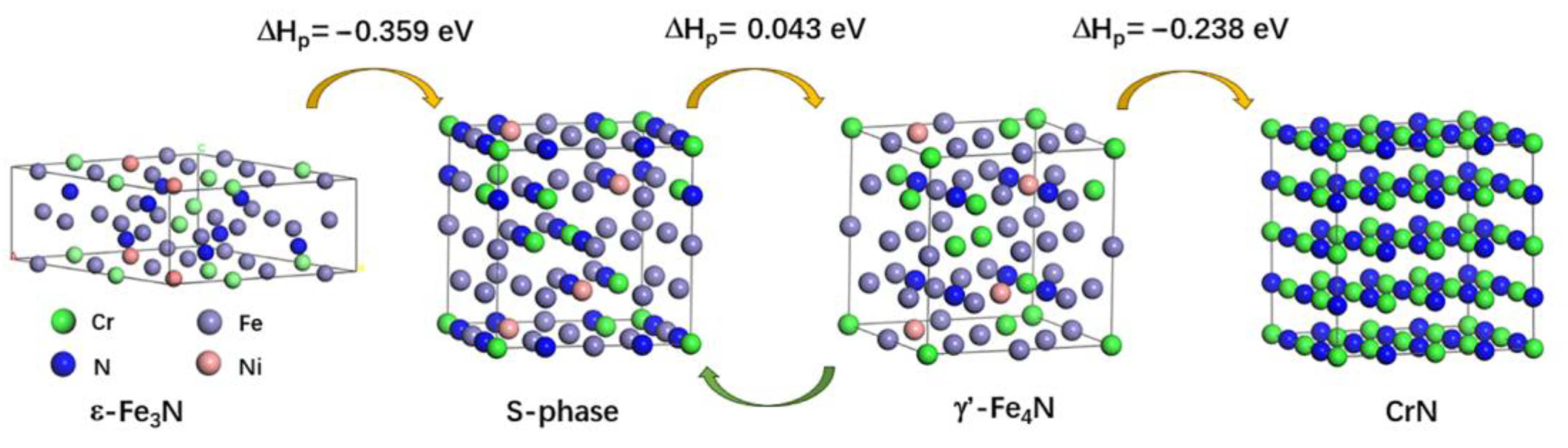
4.2. Electronic Work Functions of Formed Phases in Nitrided Layers
5. Conclusions
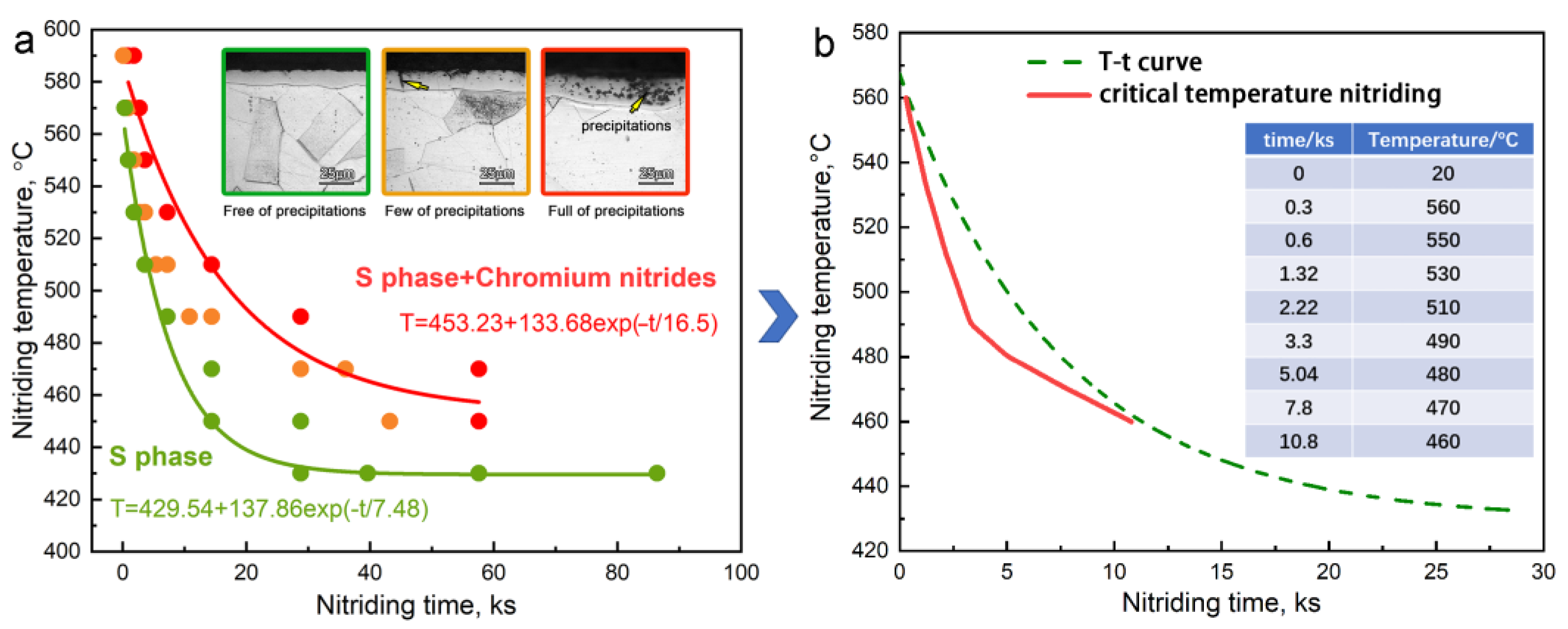
- Based on the threshold T-t curve for the gas nitriding of AISI 316L austenitic stainless steel, a novel critical temperature nitriding process has been designed and been used to fabricate the thick S-phase layer successfully.
- The maximum thickness of the S-phase layer without precipitations can reach 25 μm by the critical temperature nitriding process.
- The critical temperature nitrided surface inevitably contains massive nitrides, which is mainly composed of iron nitrides. Those iron nitrides have little influence on the corrosion resistance.
- The CTN-0.2 sample shows a comparable corrosion resistance as the conventional low-temperature nitrided one, as well as an excellent wear resistance. Its wear rate is an order of magnitude lower than that of the untreated AISI 316L austenitic stainless steel.
- The critical temperature nitriding process is a high-efficient surface modification method for austenitic stainless steels.
Author Contributions
Funding
Institutional Review Board Statement
Informed Consent Statement
Data Availability Statement
Conflicts of Interest
References
- Dong, H. S-phase surface engineering of Fe-Cr, Co-Cr and Ni-Cr alloys. Int. Mater. Rev. 2010, 55, 65–98. [Google Scholar] [CrossRef]
- Haruman, E.; Sun, Y.; Adenan, M.S. A comparative study of the tribocorrosion behaviour of low temperature nitrided austenitic and duplex stainless steels in NaCl solution. Tribol. Int. 2020, 151, 106412. [Google Scholar] [CrossRef]
- Borgioli, F.; Galvanetto, E.; Bacci, T. Corrosion behaviour of low temperature nitrided nickel-free, AISI 200 and AISI 300 series austenitic stainless steels in NaCl solution. Corros. Sci. 2018, 136, 352–365. [Google Scholar] [CrossRef]
- Tschiptschin, A.P.; Nishikawa, A.S.; Varela, L.B.; Pinedo, C.E. Thermal stability of expanded austenite formed on a DC plasma nitrided 316L austenitic stainless steel. Thin Solid Films 2017, 644, 156–165. [Google Scholar] [CrossRef]
- Zhang, X.; Wang, J.; Fan, H.; Pan, D. Erosion–corrosion resistance properties of 316L austenitic stainless steels after low-temperature liquid nitriding. Appl. Surf. Sci. 2018, 440, 755–762. [Google Scholar] [CrossRef]
- Borgioli, F.; Fossati, A.; Galvanetto, E.; Bacci, T. Glow-discharge nitriding of AISI 316L austenitic stainless steel: Influence of treatment temperature. Surf. Coat. Technol. 2005, 200, 2474–2480. [Google Scholar] [CrossRef]
- Fossati, A.; Borgioli, F.; Galvanetto, E.; Bacci, T. Glow-discharge nitriding of AISI 316L austenitic stainless steel: Influence of treatment time. Surf. Coat. Technol. 2006, 200, 3511–3517. [Google Scholar] [CrossRef]
- Borgioli, F.; Fossati, A.; Galvanetto, E.; Bacci, T.; Pradelli, G. Glow discharge nitriding of AISI 316L austenitic stainless steel: Influence of treatment pressure. Surf. Coat. Technol. 2006, 200, 5505–5513. [Google Scholar] [CrossRef]
- Li, R.; Wei, K.; Zhao, X.; Wu, M.; Liu, X.; Hu, J. Excellent behavior of coatings on 304 stainless steel by efficient low temperature plasma titanium-nitriding. Mater. Lett. 2022, 324, 132795. [Google Scholar] [CrossRef]
- Dalke, A.; Burlacov, I.; Hamann, S.; Puth, A.; Böcker, J.; Spies, H.-J.; Röpcke, J.; Biermann, H. Solid carbon active screen plasma nitrocarburizing of AISI 316L stainless steel: Influence of N2-H2 gas composition on structure and properties of expanded austenite. Surf. Coat. Technol. 2019, 357, 1060–1068. [Google Scholar] [CrossRef]
- Ohtsu, N.; Miura, K.; Hirano, M.; Kodama, K. Investigation of admixed gas effect on plasma nitriding of AISI316L austenitic stainless steel. Vacuum 2021, 193, 110545. [Google Scholar] [CrossRef]
- Bell, T. Surface engineering of austenitic stainless steel. Surf. Eng. 2002, 18, 415–422. [Google Scholar] [CrossRef]
- Gatey, A.M.; Hosmani, S.S.; Figueroa, C.A.; Arya, S.B.; Singh, R.P. Role of surface mechanical attrition treatment and chemical etching on plasma nitriding behavior of AISI 304L steel. Surf. Coat. Technol. 2016, 304, 413–424. [Google Scholar] [CrossRef]
- Hu, W.-R.; Meng, X.-Q.; Tian, Y.-F.; Sun, J.; Zhu, X.-C.; Huang, T.; Yang, X.; Du, X.-D. Surface nanocrystallization of pure iron achieved by anodization-reduction treatment and its effect on lower-temperature nitriding behaviors. Surf. Coat. Technol. 2023, 472, 129962. [Google Scholar] [CrossRef]
- Wang, L.; Sun, J.; Xu, X. Low pressure plasma arc source ion nitriding compared with glow-discharge plasma nitriding of stainless steel. Surf. Coat. Technol. 2001, 145, 31–37. [Google Scholar] [CrossRef]
- Li, Y.; He, Y.; Zhang, S.; Wang, W.; Zhu, Y. Microstructure and corrosion resistance of nitrogen-rich surface layers on AISI 304 stainless steel by rapid nitriding in a hollow cathode discharge. Appl. Phys. A 2018, 124, 65. [Google Scholar] [CrossRef]
- Li, J.; Tao, X.; Wu, W.; Xie, G.; Yang, Y.; Zhou, X.; Zhang, S. Effect of arc current on the microstructure, tribological and corrosion performances of AISI 420 martensitic stainless steel treated by arc discharge plasma nitriding. J. Mater. Sci. 2023, 58, 2294–2309. [Google Scholar] [CrossRef]
- Huang, Z.; Guo, Z.-X.; Liu, L.; Guo, Y.-Y.; Chen, J.; Zhang, Z.; Li, J.-L.; Li, Y.; Zhou, Y.-W.; Liang, Y.-S. Structure and corrosion behavior of ultra-thick nitrided layer produced by plasma nitriding of austenitic stainless steel. Surf. Coat. Technol. 2021, 405, 126689. [Google Scholar] [CrossRef]
- Gemma, K.; Kawakami, M. Enhancement of Nitriding Rate in SUS304 Austenitic Stainless Steel under Gas Nitriding. High Temp. Mater. Process. 1989, 8, 205–216. [Google Scholar] [CrossRef]
- Li, Y.; Zhang, S.; He, Y.; Zhang, L.; Wang, L. Characteristics of the nitrided layer formed on AISI 304 austenitic stainless steel by high temperature nitriding assisted hollow cathode discharge. Mater. Des. 2014, 64, 527–534. [Google Scholar] [CrossRef]
- Zhang, C.S.; Yan, M.F.; You, Y.; Chen, H.T.; Zhang, F.Y.; Bai, B.; Chen, L.; Long, Z.; Li, R.W. Stability and properties of alloyed ε-(Fe1−xMx)3N nitrides (M = Cr, Ni, Mo, V, Co, Nb, Mn, Ti and Cu): A first-principles calculations. J. Alloys Compd. 2014, 615, 854–862. [Google Scholar] [CrossRef]
- Brumovsky, M.; Oborná, J.; Micić, V.; Malina, O. Iron nitride nanoparticles for enhanced reductive dechlorination of trichloroethylene. Environ. Sci. Technol. 2022, 56, 4425–4436. [Google Scholar] [CrossRef] [PubMed]
- Tong, K.; Ye, F.; Wang, Y.K. Short-range ordered structure and phase stability of supersaturated nitrided layer on austenitic stainless steel. Acta Mater. 2019, 175, 314–323. [Google Scholar] [CrossRef]
- Zhang, Z.; He, G.; Chen, J. First-principles study of the stability, electronic and mechanical properties of Cr2N and CrN with the variation of Ni doping concentration. Ceram. Int. 2021, 47, 24430–24437. [Google Scholar] [CrossRef]
- Device Studio, Version 2021A; Hongzhiwei Technology: Shanghai, China. 2021. Available online: https://cloud.hzwtech.com/web/personal-space/compute-enter/computing-resources (accessed on 1 October 2020).
- Blochl, P.E. Projector augmented-wave method. Phys. Rev. B 1994, 50, 17953–17979. [Google Scholar] [CrossRef] [PubMed]
- Kochmański, P.; Długozima, M.; Baranowska, J. Structure and Properties of Gas-Nitrided, Precipitation-Hardened Martensitic Stainless Steel. Materials 2022, 15, 907. [Google Scholar] [CrossRef]
- Shen, L.; Wang, L.; Xu, J.J. Plasma nitriding of AISI 304 austenitic stainless steel assisted with hollow cathode effect. Surf. Coat. Technol. 2013, 228, S456–S459. [Google Scholar] [CrossRef]
- Tao, X.; Liu, X.; Matthews, A.; Leyland, A. The influence of stacking fault energy on plasticity mechanisms in triode-plasma nitrided austenitic stainless steels: Implications for the structure and stability of nitrogen-expanded austenite. Acta. Mater. 2019, 164, 60–75. [Google Scholar] [CrossRef]
- Yan, M.F.; Zhang, C.S.; Sun, Z. Study on depth-related microstructure and wear property of rare earth nitrocarburized layer of M50NiL steel. Appl. Surf. Sci. 2014, 289, 370–377. [Google Scholar] [CrossRef]
- Jasper, S.; Vijayakumar, D.; Ravichandran, M.; Sankarlal, R.; Subash, R. Micro structure and wear analysis of multi-layer nitride coating deposited on the austenitic steel. Mater. Today Proc. 2023, 5, 298. [Google Scholar] [CrossRef]


| Samples | Temperature (°C) | Time (h) | NH3 (L/min) |
|---|---|---|---|
| GN430 | 430 | 8, 11, 16, 24 | 0.8 |
| GN450 | 450 | 4, 8, 12, 16 | |
| GN470 | 470 | 4, 8, 10, 16 | |
| GN490 | 490 | 2, 3, 4, 8 | |
| GN510 | 510 | 1/2, 1, 2, 4 | |
| GN530 | 530 | 1/2, 3/4, 1, 2 | |
| GN550 | 550 | 1/4, 1/3, 1/2, 1 | |
| GN570 | 570 | 1/12, 1/6, 1/4, 3/4 | |
| GN590 | 590 | 1/60, 1/12, 1/4, 1/2 |
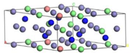
| Phases | Formula | Formula | |
|---|---|---|---|
| S-phase | Fe23Cr6Ni3N12 | Fe22Cr7Ni3N12 | |
 | 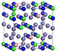 | ||
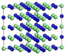
| γ’-Fe4N | Fe22Cr7Ni3N8 | Fe21Cr8Ni3N8 | |
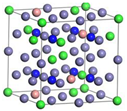 | 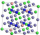 | ||
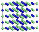
| ε-Fe3N | Fe17Cr5Ni2N8 | Fe16Cr6Ni2N8 | |
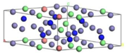 |  | ||
| CrN | Cr32N32 | 100 at.% | Cr31FeN32 |
 |  | ||
| Samples | Corrosion Potential (V) | Corrosion Current Density (A/cm2) |
|---|---|---|
| Untreated | −0.38518 | 5.0995 × 10⁻⁶ |
| GN430-24 (nitrided surface) | −0.89202 | 1.7399 × 10⁻⁵ |
| CTN-0.2 (nitrided surface) | −0.88578 | 5.1024 × 10⁻⁵ |
| CTN-0.4 (nitrided surface) | −0.66256 | 5.4824 × 10⁻⁵ |
| CTN-0.8 (nitrided surface) | −0.9173 | 1.9674 × 10⁻⁵ |
| GN430-24 (polished surface) | −0.33879 | 3.7034 × 10⁻⁷ |
| CTN-0.2 (polished surface) | −0.39407 | 1.2909 × 10⁻⁸ |
| CTN-0.4 (polished surface) | −0.49179 | 1.2446 × 10⁻⁵ |
| CTN-0.8 (polished surface) | −0.57112 | 6.8901 × 10⁻⁷ |
| Reactions | , eV |
|---|---|
| S (Fe22Cr7Ni3N12) + Cr31FeN32 → S (Fe23Cr6Ni3N12) + Cr32N32 | −0.194 |
| S (Fe22Cr7Ni3N12) + γ’ (Fe22Cr7Ni3N8) → S (Fe23Cr6Ni3N12) + γ’ (Fe21Cr8Ni3N8) | 0.043 |
| S (Fe22Cr7Ni3N12) + ε (Fe17Cr5Ni2N8) → S (Fe23Cr6Ni3N12) + ε (Fe16Cr6Ni2N8) | 0.359 |
Disclaimer/Publisher’s Note: The statements, opinions and data contained in all publications are solely those of the individual author(s) and contributor(s) and not of MDPI and/or the editor(s). MDPI and/or the editor(s) disclaim responsibility for any injury to people or property resulting from any ideas, methods, instructions or products referred to in the content. |
© 2023 by the authors. Licensee MDPI, Basel, Switzerland. This article is an open access article distributed under the terms and conditions of the Creative Commons Attribution (CC BY) license (https://creativecommons.org/licenses/by/4.0/).
Share and Cite
Tang, D.; Zhang, C.; Zhan, H.; Huang, W.; Ding, Z.; Chen, D.; Cui, G. High-Efficient Gas Nitridation of AISI 316L Austenitic Stainless Steel by a Novel Critical Temperature Nitriding Process. Coatings 2023, 13, 1708. https://doi.org/10.3390/coatings13101708
Tang D, Zhang C, Zhan H, Huang W, Ding Z, Chen D, Cui G. High-Efficient Gas Nitridation of AISI 316L Austenitic Stainless Steel by a Novel Critical Temperature Nitriding Process. Coatings. 2023; 13(10):1708. https://doi.org/10.3390/coatings13101708
Chicago/Turabian StyleTang, Daodong, Chengsong Zhang, Haoting Zhan, Wenao Huang, Zongkai Ding, Dazhi Chen, and Guodong Cui. 2023. "High-Efficient Gas Nitridation of AISI 316L Austenitic Stainless Steel by a Novel Critical Temperature Nitriding Process" Coatings 13, no. 10: 1708. https://doi.org/10.3390/coatings13101708