Article

Improvement of the Mechanical Properties of 30CrNi2MoVA through Ultrasonic-Milling in Certain Key Components

1
Northwest Institute of Mechanical & Electrical Engineering, Xianyang 712000, China
2
Institute of Mechanical Engineering, Zhejiang University, Hangzhou 310030, China
*
Author to whom correspondence should be addressed.
Coatings 2023, 13(9), 1626; https://doi.org/10.3390/coatings13091626
Submission received: 27 July 2023 / Revised: 7 September 2023 / Accepted: 10 September 2023 / Published: 16 September 2023
(This article belongs to the Special Issue Coating Technologies Involving Surface Adsorption and Diffusion)

Abstract

:
To improve the fatigue life of the key component and the surface properties of the 30CrNi2MoVA steel material, advanced ultrasonic-milling composite superficial treatment was performed. The microstructure, surface roughness, friction and wear performance, surface hardness, fatigue life and environmental experiments of the steel with and without ultrasonic-milling have been carried out in detail. In comparison with those of the traditional dry cutting, the results show that the surface roughness of the samples after the advanced ultrasonic-milling surface modification fluctuates about 0.32 μm, and the surface hardness is increased by about 40% compared with the matrix hardness, and the fatigue life of the pump head connection shaft has been increased by more than 11 times. Advanced ultrasonic-milling surface modification technology can increase the local residual compressive stress and wear resistance on the material surface, which can make the material have better surface properties.

1. Introduction

30CrNi2MoVA steel is a kind of low-alloy high-strength structural steel, which has good comprehensive mechanical properties after tempering. The steel is widely used in the manufacture of large forgings with high strength and toughness, such as thermal power; nuclear power plant equipment; large metallurgical, mining and transportation equipment in the bearing; and transmission structural components. The fracturing machine is an important piece of equipment in the process of oil mining, and the pump head connection shaft of the core components in the pump valve box is made of this alloy. Due to the double action of cyclic fatigue load and corrosive medium, it will crack and fail after dozens of hours in use.
Ultrasonic action is an auxiliary means of influencing the surface state during dynamic impact [1,2], which was used to improve the fatigue intensity of welded joints, and then other related technologies were developed to increase the resistance of metal materials to fatigue, friction, wear and corrosion, mainly including ultrasonic wear and corrosion, mainly including ultrasonic shot peening and ultrasonic rolling [3,4]. Tianjin University processed the welded joints of low-carbon steel, titanium alloy and high-carbon steel using ultrasonic technology, and the research results show that this technology can greatly improve the fatigue properties of materials [5]. Feng Gan and coworkers found that ultrasonic shot peening technology can form nanolayers of a certain thickness on the surface of 20 steel [6]. Liu Yu and coworkers showed that ultrasonic rolling technology can improve the hardness and elastic modulus of the material surface [7]. Yan Mufu et al. [8] proposed a method to realize the steel surface nanometer layer based on thermal diffusion technology, but the process of this method is complicated and time consuming. With the development of science and technology in recent years, ultrasonic technology has been introduced to improve the surface hardness of materials and reduce the machining roughness, such as ultrasonic rolling and ultrasonic strengthening [9,10]. Zhao Bo et al. [11] studied ultrasonic rolling technology, which can make plastic deformation of the metal surface and refine the surface texture and improve the surface hardness and machining surface roughness. Xu Quanjun et al. [12] found that when the superficial treatment of ultra-high strength steel adopts ultrasonic rolling strengthening technology, a hardening layer would be formed on the surface of the sample because of the residual compressive stress. The surface roughness of the sample is reduced to the nanometer level, which is 96.7% lower than the original roughness, and the surface microhardness is increased by 55.1%. Xu Shenghang [13] et al. found that the surface roughness of materials after ordinary shot peening was 1.5 times that after ultrasonic shot peening; it shows that the surface roughness of the material will decrease significantly through ultrasonic vibration. Fouad Y [14] et al. conducted a comparative study on the effects of shot peening and rolling on the high-strength ZK60 magnesium alloy high-cycle fatigue properties and found that the fatigue limits after shot peening and rolling were increased by 17% and 33%, respectively. Ultrasonic and other surface modification technologies can not only improve the hardness of the material surface, but also increase the density of the material surface [15,16].
The related research of ultrasonic action has been widely studied, but its application in the field of 30CrNi2MoVA is not deep enough. For the 30CrNi2MoVA material, surface modification is carried out to improve its comprehensive performance, including friction and wear, fatigue and environmental corrosion, and reveal its microscopic mechanism.

2. Experimental Section

2.1. Experimental Materials and Testing System

The experiments were performed at Northwest Institute of Mechanical & Electrical Engineering, China. 30CrNi2MoVA steel is used in the field of pump head commonly. It plays an important role in the oil mining industry. Its chemical composition is shown in Table 1. Furthermore, in this study, the pump head connection shaft samples with a diameter of 8.7 mm and length of 8 mm, made of rodlike material, were processed in a CK6150 numerical control lathe. The connection shaft samples were treated to achieve a hardness of 350 HV. Ultrasonic static pressure is the key parameter. By changing the pressure, the static pressure exerted by the ultrasonic device on the workpiece surface is set to be 779 N. Under the same static pressure, the workpiece is continuously strengthened by ultrasonic compound processing for three times. The workpieces treated by traditional cutting were taken as the comparison specimen and advanced ultrasonic-milling composite surface modification treatments. The surface roughness and surface hardness of the experimental samples were measured by a contact surface profiler (Taylor Surtronic 25) and a HR-150A microhardness tester, respectively. The experimental data were averaged for multiple measurements. The residual stress was measured by a HS 1010 ultrasonic residual stress detector. The microstructure of the top cross-section of the KH-7700 digital microscope material was observed. Finally, it is necessary to carry out environmental tests, such as rain, salt spray, damp heat, high and low temperature, on the samples according to the test requirements of the corresponding environmental test standards (GB/T 2423-2012).

2.2. Advanced Ultrasonic-Milling Composite Surface Modification (AUMSM) Technology

Advanced ultrasonic-milling composite surface modification is a new technology of using the composite energy of activation energy and impact energy to process metal parts, so that the surface of the parts can achieve the mirror effect and be modified [17]. It is the edge science of physics, vibration, ultrasonic, mechanical processing, force and so on. Advanced ultrasonic-milling composite surface modification treatment initiated a new machining process beyond the traditional mechanical processing technology of turning, milling, planning and grinding, which is a revolutionary and subversive innovation in the machining field and achieves the mechanical processing with a non-mechanical processing idea. Firstly, the metal materials of the workpieces can be improved by the ultrasonic vibration energy and the static pressure. Second, the tool head hits the part surface at the frequency of 30,000 times per second. Once again, the ultrasonic tools move the machining path, so that the metal flows from the high point to the low point to meet the desired surface roughness requirements under the dual energy effect. In other words, the advanced ultrasonic-milling composite surface modification treatment can iron the surface of the parts and produce pressure stress to improve the surface microhardness and abrasion resistance and prolong the fatigue life of the workpieces.

2.3. Fatigue Test Conditions

With the help of a microcomputer control electro-hydraulic servo fatigue experiment machine (PWS-100), the fatigue life of pump head connection shaft samples was investigated. The sample loading form and size annotation are shown in Figure 1, where the diameter of the fatigue sample is 40 mm, and the clamping length of the hydraulic upper and lower fixture of the fatigue machine is 150 mm. Ten experiments were performed with the maximum load of 360 KN, amplitude of 162 KN, stress ratio of 0.1 and frequency of 5 Hz sinusoidal alternating stress, through each of two groups of pump head connection shaft samples. The loading photos of fatigue specimens are presented in Figure 1.

3. Results and Analysis

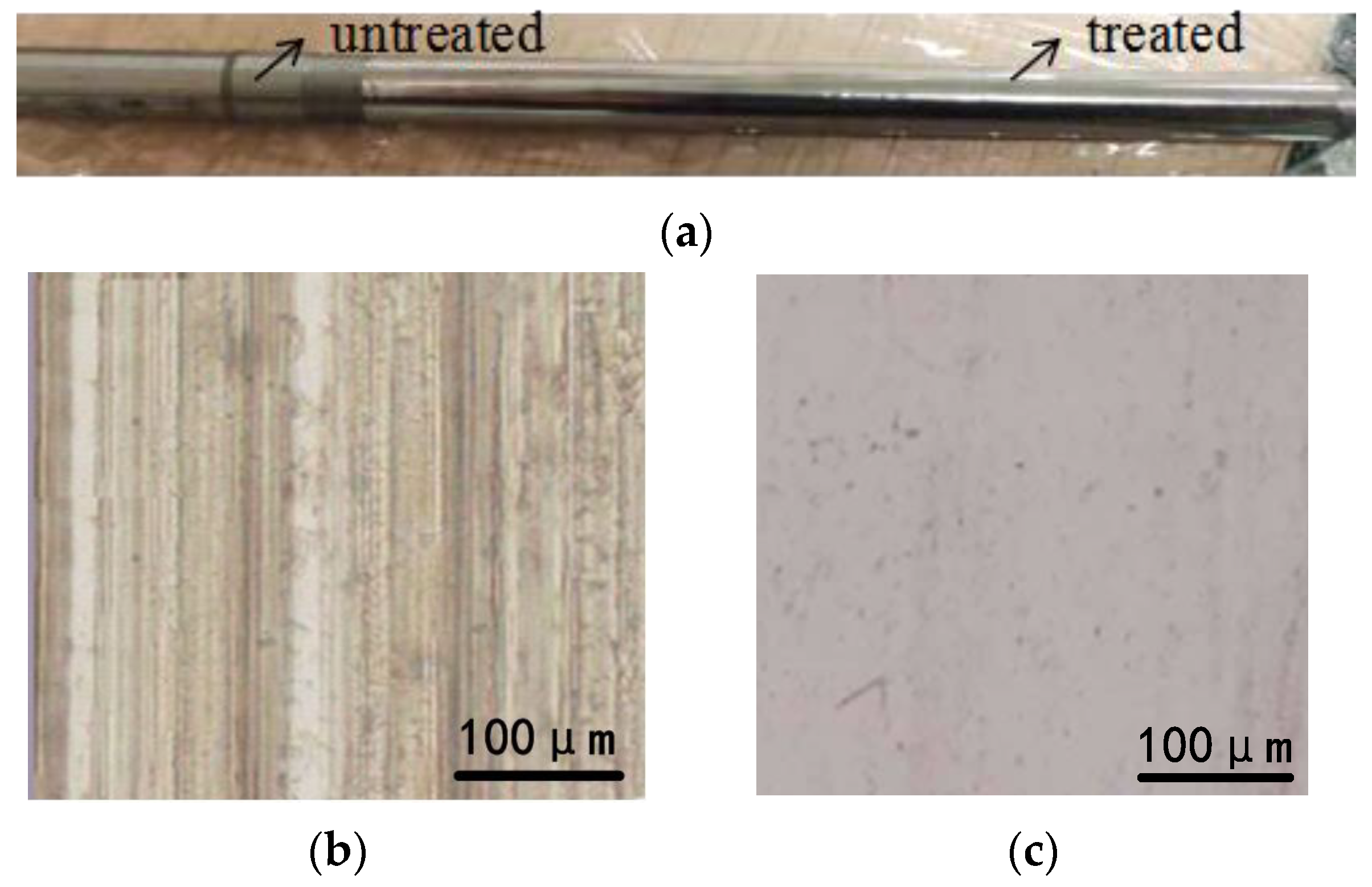
3.1. Surface Roughness and Surface Topography

Figure 2 is a macroscopic photo of the surface of untreated and AUMSM-treated samples. The surface structure without AUMSM treatment is shown in Figure 2b. The surface is uneven, and the roughness is high. The surface parallel lines formed after machining and cutting are more obvious, which is the reason for the reduction of the fatigue life of parts. The surface of the part after AUMSM treatment is smoother and less rough (shown in Figure 2c). Obviously, AUMSM treatment can eliminate the surface grooves of the material. It has also been confirmed that ultrasonic nanocrystalline surface modification (UNSM) can improve the surface roughness, microhardness and compressive residual stress of bearings, and micro-pits can improve the fatigue life of bearings with relative motion oil film thickness [17,18,19,20,21]. The experimental results further show that the surface after AUMSM treatment is better than that after conventional cutting treatment [22].
The surface roughness under two different treatments is shown in Table 2. The surface roughness reduced from 1.6 μm to 0.32 μm under AUMSM treatment, which is mainly related to the frequency and the roughness of the ultrasonic vibration head. The machining target of the pump head connection shaft surface is Ra ≤ 0.4 μm, and the AUMSM technology meets the machining requirements.

3.2. Microhardness

As shown in Table 3, the hardness of the sample substrate after conventional cutting and heat treatment is 471 HV. On this basis, the surface hardness is increased to 660 HV after AUMSM treatment, which is increased by 40%. AUMSM technology will form a hardened layer on the surface of the sample and accumulate a large amount of surface compressive stress, thereby improving the friction performance, wear resistance and fatigue life of key components. The reason why the surface hardness cannot be greatly increased may be related to the yield limit of the material.
What is more, it is obvious that conventional cutting had a smaller deformation range than AUMSM. Figure 3 is the depth profile of the hardness of the samples under two treatments. As shown in Figure 3a, the hardness at the surface increased rapidly after AUMSM for 660 HV treated with respect to the cutting treatment for 471 HV. To be noted, the AUMSM surface hardened layer is about 900 μm in depth, far deeper than that of cutting specimens to 500 μm. In order to better illustrate the distributed uniformity of the surface hardness after AUMSM treatment, different directions of the treated sample were selected to test the hardness distribution. As shown in Figure 3b, there are three directions, namely, X, Y and Z. Figure 3c shows the hardness distributions of the treated cross-section in the X and Y directions have good coincidence and that in the Z (surface) direction keeps about 660 HV with a little fluctuation. This means that AUMSM treatment can improve the hardness of the materials equably and efficiently.

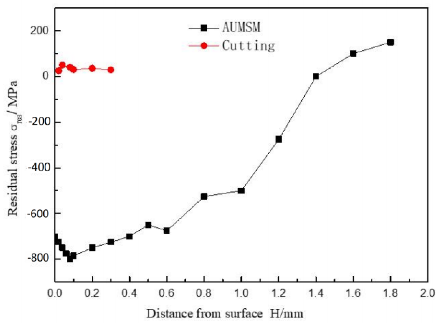
3.3. The Ideal Compressive Stress

It can be seen from Figure 4 that the surface pressure of the sample after AUMSM treatment is greatly reduced compared with the original sample, which 100% eliminates tensile stress and presets high-value controllable compressive stress. The residual tensile stress can accelerate the corrosion of the parts in the application environment, also known as stress corrosion, but the residual compressive stress can greatly inhibit it in the same conditions. It can be concluded that the corrosion resistance of key parts will be greatly improved after AUMSM treatment.

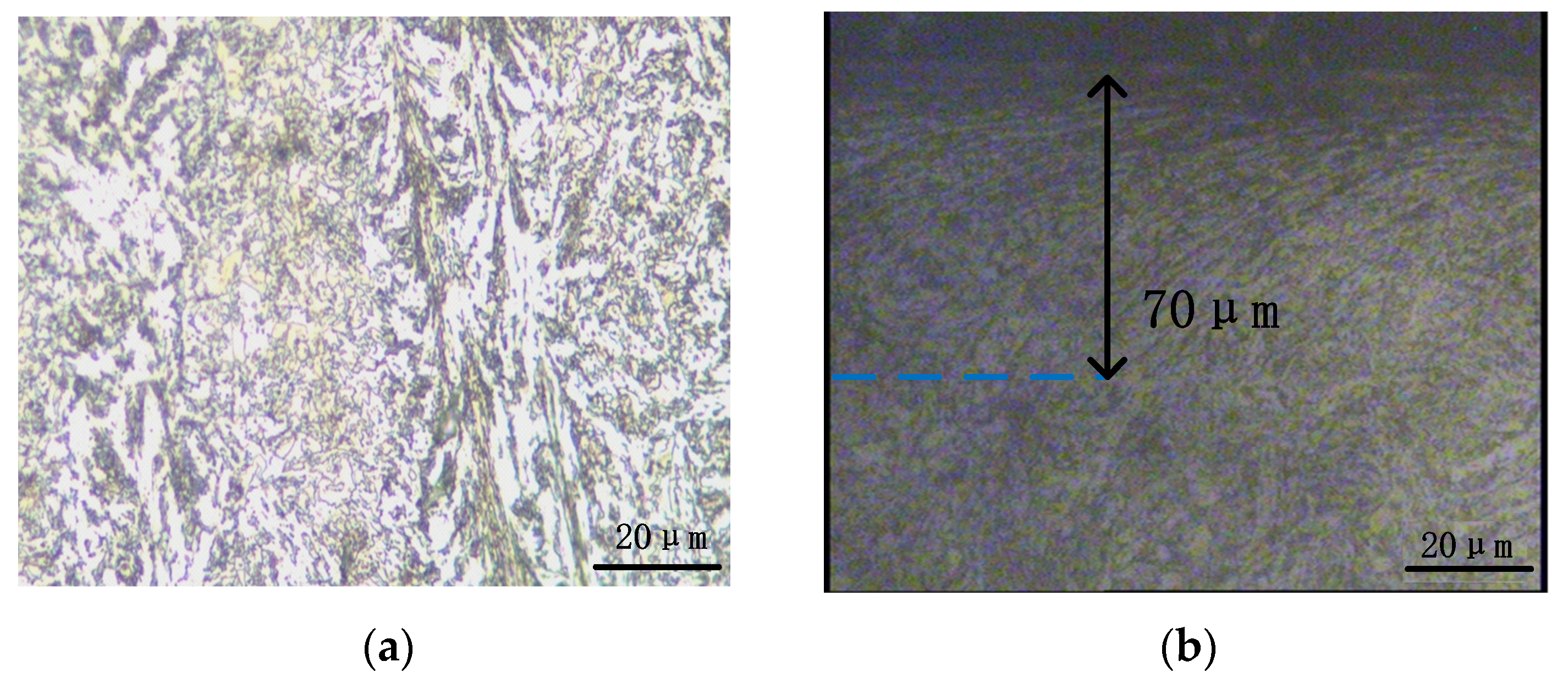
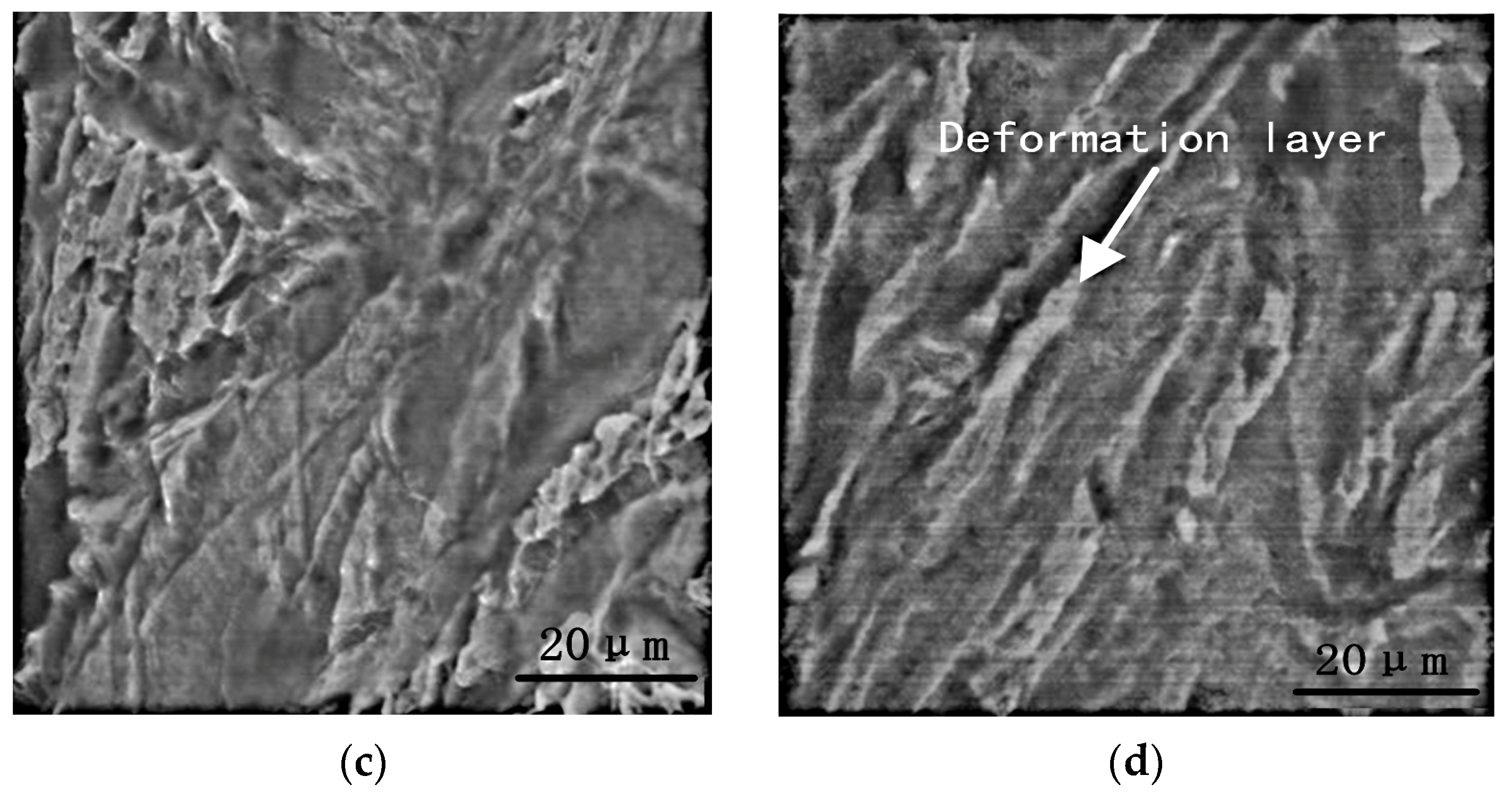
3.4. Microstructures

The results of the analysis of the surface crystal texture of the sample after conventional cutting and AUMSM treatment are shown in Figure 5. The matrix of the pristine sample has fine martensite and vanadium carbides, which behave relatively uniformly (Figure 5a). A grain deformation layer was formed on the 30CrNi2MoVA alloy constructional steel sample’s surface during the AUMSM process (Figure 5b). The thickness of the affected zone was about 70 μm. Compared with the traditional turning, the surface hardness and the thickness of the hardened layer and grain deformation layer of the samples are significantly increased. The cross-section at the distance of 30 μm from the surface was further investigated by SEM analysis to observe the magnification morphologies, as shown in Figure 5c,d. Figure 5c shows the matrix structure. Figure 5d reveals that on the top of the specimen surface, there appears an obvious deformation layer after AUMSM treatment. The direction of the layer is roughly the same as the direction of ultrasonic rolling in streamline distribution. Additionally, a large number of particles on the surface of the specimen are deformed and refined to form the rheological hardened layer of a certain thickness, which can improve the hardness, wear resistance and corrosion resistance of the material surface, and can also improve the fatigue resistance of the material [23,24,25].

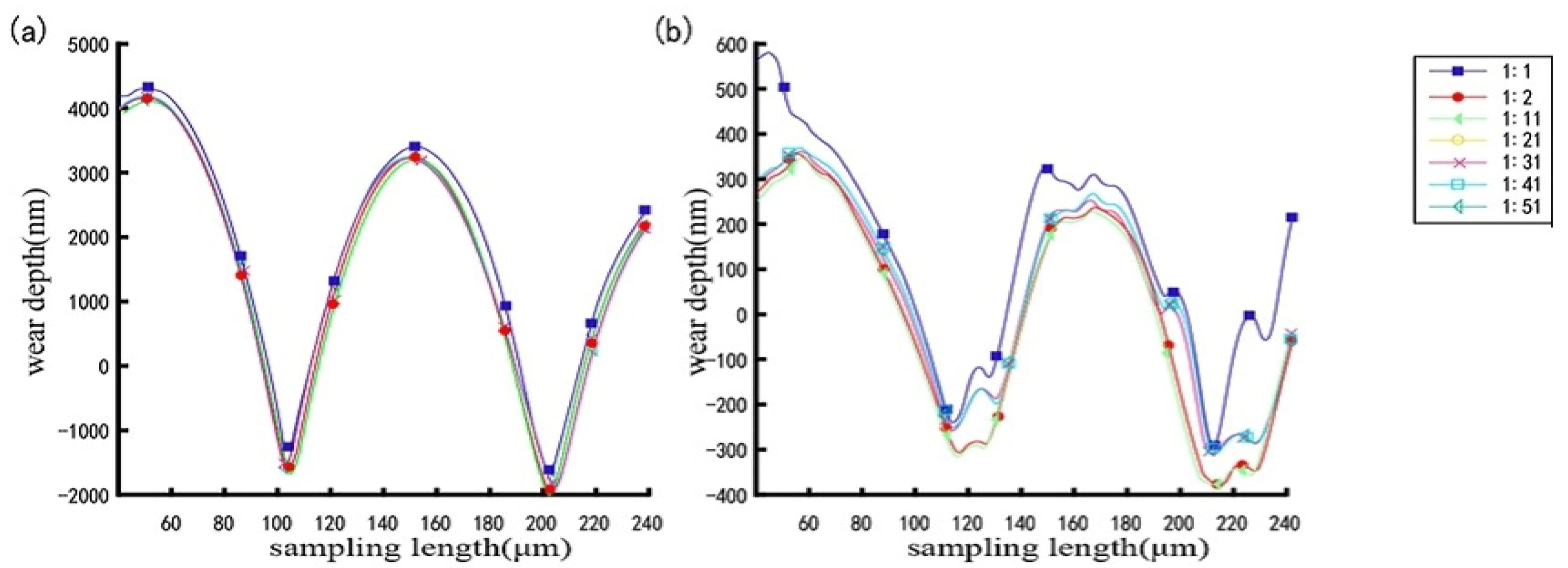
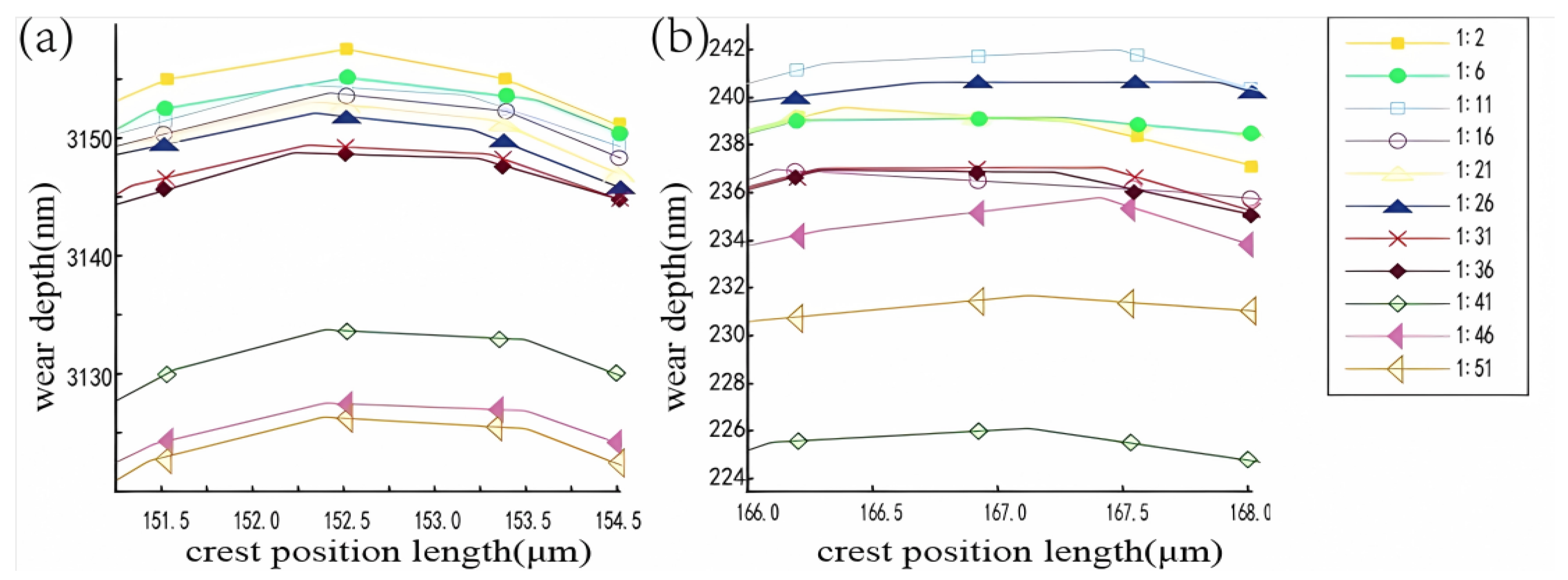
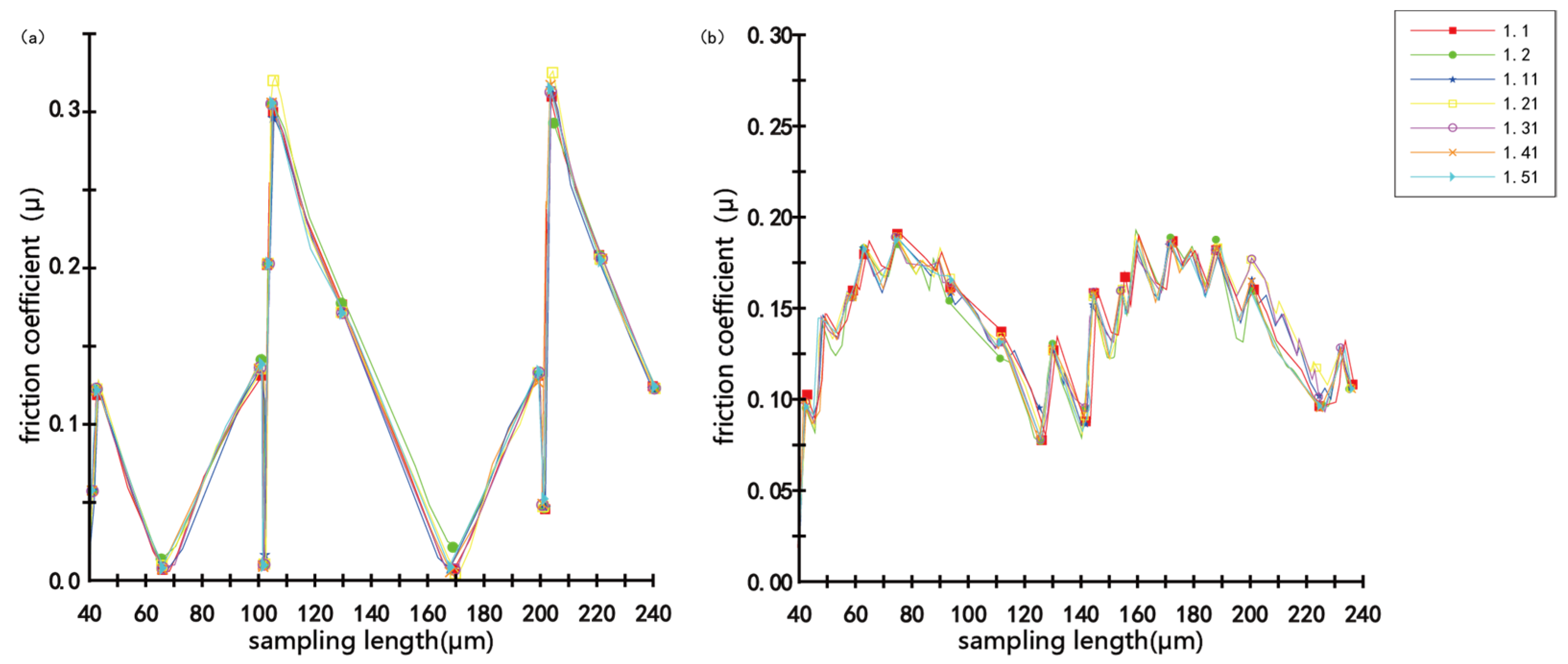
3.5. Friction and Wear Properties

As shown in Figure 6, the relationship between wear depth and distance is investigated by Nano Indenter G200-1:1 is for the primary morphology, 1:2 is the first wear morphology, 1:11 is the tenth morphology and the rest is finished in the same way. In Figure 6, “:” indicates the number of cycles, while “1:” represents a benchmark. The “1:1” line represents the original shape of the workpiece, which means no (1-1 = 0) wear was introduced to the workpiece. The “1:2” line represents the morphology of the workpiece after the first (2-1 = 1) wear with pressure. The “1:11” line represents the morphology after the 11th wear with pressure. By that analogy, the wear depth curves are the morphology of the workpiece after a corresponding wear. Figure 6a is the original sample, which shows that all curves have better coincidence, but its ordinate span is much larger. It shows that the surface of the original sample is uneven, and the quality is poor. The big distance between the first curve and the other curves indicates that the wear amount is relatively large. In the scratch distance of 240 μm, the most wear depth is 4 μm. However, as shown in Figure 6b, all curves were worn less than the original curve, the most wear depth of which is 0.3 μm. In addition, the distance between the wear curves and the 1:1 curve in Figure 6a is close to 400 nm. But, that in Figure 6b is about 100 nm, which is smaller than that shown in Figure 6a. From the ordinate view, the surface quality of the specimens processed by AUMSM are greatly improved owing to the surface refined layers.
In order to show the difference in wear amount more clearly, Figure 7 enlarges the crest part in Figure 6 and shows the actual wear depth of the 11 selected wear curves for 30CrNi2MoVA alloy constructional steel specimens before and after the AUMSM treatment. The “1:1” line is the original shape of workpiece, that is, the wear shape curve of the specimen surface without wear pressure. Figure 7a represents the original sample, and the span of the ordinate curve is over 30 nm. The disparity between the first and other curves indicates that the wear amount is relatively large under pressure. On the contrary, the total span of the 11 selected wear depths decreases from 30 nm to 17 nm in Figure 7b, which is the wear curves of the workpiece surface after AUMSM treatment. It can be found the surface finish of the workpiece has been greatly improved after AUMSM treatment. In summary, it can be show that the workpiece surface after AUMSM treatment is more resistant to wear, and the stability is increased. Due to the increase in hardness and residual compressive stress, the friction and wear performance of the specimen was improved by more than 43%.
Figure 8 shows the variation of the friction coefficient of samples in friction and wear experiments. Figure 8a is the original sample and Figure 8b is the curve of the AUMSM sample. It is same as the above wear curve, where 1.1 is the original friction coefficient, 1.2 is the friction coefficient obtained from the first friction cycle, and the curve 1.11 is the friction coefficient curve obtained from the 10th friction and wear experiment. By analogy, curve 1.51 is the friction coefficient curve in the 50th friction and wear experiment. It can be seen from Figure 8a that the friction coefficient of the original sample fluctuates greatly with the wear distance curve and changes in a broken line, mainly because the surface roughness of the original sample is poor and there are multiple turning marks. The maximum friction coefficient is 0.31. However, the roughness of the sample after AUMSM treatment is better. The maximum friction coefficient is significantly reduced to 0.19, and the fluctuation range is relatively small, indicating that the material becomes more wear resistant after AUMSM treatment. The decrease of the scatter of the friction coefficient is due to two factors. One is the hardening effect on the surface of the material after AUMSM treatment, and the other is the low roughness and good lubrication of the surface after AUMSM treatment. In some points, the friction of the untreated sample is even lower than that of the treated one, which may be because the measured points of the untreated sample were carbides. The friction coefficient increases with the increase in the wear length. The reason for this phenomenon is that the wear debris generated on the surface of the sample during the friction and wear test will lead to an increase in the friction coefficient.
The analysis shows that the above-mentioned effects are caused by the following three aspects. Firstly, the surface hardness is significantly improved by work hardening and martensite refinement. Secondly, the AUMSM treatment samples have a relatively smooth surface and low surface roughness. Finally, due to the large compressive residual stress generated by AUMSM treatment, the initiation and propagation of microcracks are inhibited [26,27].

3.6. Fatigue Life

On the basis of the fatigue test, five groups of fatigue loading tests were carried out on the pump head connection shaft specimens under different technologies at the stress ratio (R = 0.1). The obtained fatigue life is shown in Table 4, which shows that the fatigue life of the samples treated with AUMSM is increased by 10.5%, 17.1%, 6.2%, 8.4% and 10.6% at 9422 times, 11,679 times, 7075 times, 9770 times and 10,172 MPa, respectively, compared to the untreated specimen. The cycles number of the fatigue life for the AUMSM specimens ranged from 9000 to 11,000 cycles, with an average of 9624 cycles, but that for the TC is about 800~1000 cycles, with the average of 874 cycles. The fatigue test results show that the fatigue life of the pump head connection shaft can be increased by more than 11 times after being treated with AUMSM technology. It can be concluded that the AUMSM treatment was found to promote the fatigue life improvement of key components.
Figure 9 shows the fatigue fracture of pump head connection shaft specimens. The fracture occurred at the root of the skew tooth of the pump head connection shaft, which is consistent with the failure in the process of actual use; it shows that the fatigue life test of the pump head connection shaft sample is effective.
The fatigue fractography images of the 30CrNi2MoVA are shown in Figure 10, through the stress and failure process analysis, of which such as the pump head connection shaft, it is found that the crack source is located in the area of the lower end of the fracture, without obvious plastic deformation, and the edge has sheer lip characteristics. According to the ring tension and compression stress it is subjected to and the fracture characteristics, it is judged that the fracture belongs to the strain reduction fracture, which is mainly composed of the fracture source region and the crack rapid expansion region. The fracture source belongs to the line crack source, which is located near the peripheral region of the parts and occupies a relatively small area without fatigue steps. However, the area of rapid crack growth is larger, accounting for more than 80% of the fracture area. Additionally, the characteristics of microporous fracture can be faintly observed between the extrusion trace regions. The microporous fracture failure stress concentration is largely due to concentrated stress. In this regard, it is necessary to improve the fatigue life of the pump head connection shaft by controlling the surface properties of key components.
The mechanical calculation analysis and computer simulation processing for the fatigue specimens are shown in Figure 11. The load is 30,000 KN, and the yield limit of the steel is 785 MPa. The simulation results show that the maximum stress value of the sample is 992 MPa, which appears at the skew tooth of the pump head connection shaft, which is consistent with the test fracture position. The structure of the tooth surface and the transition fillet of the connection shaft are optimized, where the transition fillet is from 1 to 2 mm, the structural accuracy is from 0.05 to 0.03 mm, and the roughness is from 0.08 to 0.04.
AUMSM mainly improves the surface quality of workpieces through improving the cold plastic properties of metals at room temperature and local residual compressive stress. AUMSM technology can reduce the occurrence of microcracks and compressive stress in metallic materials, thereby improving the surface quality of samples and prolonging their fatigue life.

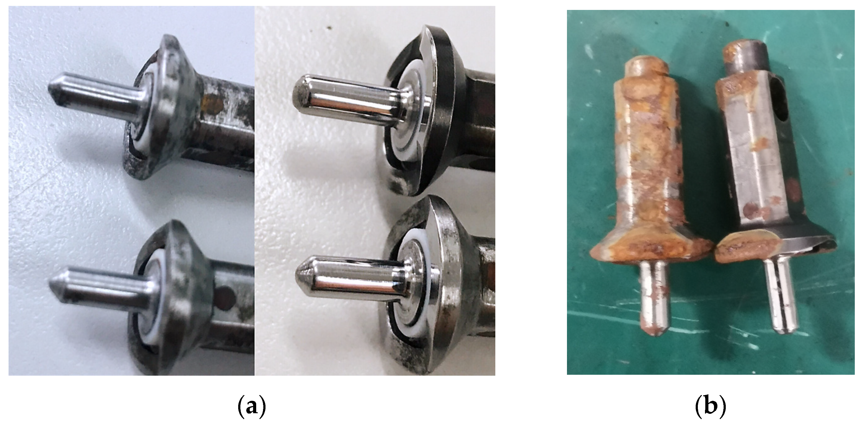
3.7. Environmental Experiment Results

The pump head movable pin samples were placed in the salt spray simulation laboratory, wet and hot simulation laboratory, high- and low-temperature simulation laboratory, rain simulation laboratory for environmental tests. Samples were visually inspected and photographed prior to testing. Figure 12a is the comparison of samples before the environmental test. The picture on the left shows the two samples after conventional dry cutting, and the right side shows that two samples after ultrasonic composite strengthening modification (UCSM) treatment. UCSM treatment has been shown to improve surface quality and fatigue life [28]. It is obvious that the surface finish of the sample is higher after UCSM treatment. Figure 12b is the environmental test results. The left side shows the traditional turning sample with severe surface corrosion on surface, while the right side shows no serious corrosion and damage after ultrasonic composite strengthening. UCSM treatment also can improve the corrosion resistance of the material surface. When used in a harsh environment, the lifespan of the material is highly improved, which can meet the needs of high reliability and long lifespan.

4. Conclusions

In the fatigue life test, two different pump head connection shaft samples were compared, and the results showed that the fatigue life of the sample treated with advanced ultrasonic-milling surface modification was longer than that of the conventionally cut sample. From this it can be concluded:
  • By AUMSM treatment, it eliminated the uneven grooves caused by conventional cutting, and the surface roughness was reduced from 1.16 μm to 0.32 μm.
  • The surfaces have good coincidence, and the surface hardness after the AUMSM treatment was increased by 40% than the matrix hardness, where the surface hardened layer is about 900 μm in depth, far deeper than that of cutting specimens to 500 μm.
  • The material processed by AUMSM technology has suitable compressive stress and strong wear resistance. The fatigue life of the pump head connection shaft was increased by more than 11 times. Moreover, the corrosion resistance of the material is improved by UCSM. The results of this study are significant for the design of key components that help to improve their durability and reliability.

Author Contributions

Conceptualization, J.L.; Methodology, D.L.; Formal analysis, Y.S.; Investigation, H.W.; Data curation, K.W.; Writing—original draft, E.W.; Writing—review & editing, E.W.; Visualization, J.S. All authors have read and agreed to the published version of the manuscript.

Funding

The work was financially supported by the National Natural Science Foundation of China (No. 52001261).

Institutional Review Board Statement

Not applicable.

Informed Consent Statement

Not applicable.

Data Availability Statement

The data presented in this study are available on request from the corresponding author.

Conflicts of Interest

The authors declare no conflict of interest.

References

  1. Liu, X.C.; Zhang, H.W.; Lu, K. Strain-Induced ultrahard and ultrastable nanolaminated structure in Nickel. Science 2013, 342, 337–340. [Google Scholar] [CrossRef]
  2. Yasuoka, M.; Wang, P.; Zhang, K. Improvement of the fatigue strength of SUS304 austenite stainless steel using Ultrasonic nanocrystal surface modification. Surf. Coat. Technol. 2013, 218, 93–98. [Google Scholar] [CrossRef]
  3. Zhu, Y.L.; Wang, Y.L.; Bian, F.L. Progresses on Research and Application of Metal Ultrasonic Surface Enhancement Technologies. J. Mech. Eng. 2014, 50, 35–45. [Google Scholar] [CrossRef]
  4. Chen, L.; Wang, H.B.; Liu, D. Surface nanocrystallization of C45E4 steel by ultrafast electropulsing-ultrasonic superficial treatment. J. Wuhan Univ. Technol. (Mater. Sci.) 2017, 32, 1426–1431. [Google Scholar] [CrossRef]
  5. Wang, D.P.; Huo, L.X.; Zhang, Y.F. Fatigue performance improvement of titanium alloy welded joint by ultrasonic impact method. Chin. J. Nonferrous Met. 2003, 13, 1456–1460. [Google Scholar]
  6. Feng, G.; Shi, L.J.; Lu, J. Investigation of sueface nnanocrystallization of a low carbon steel induced by ultrasonic sshot peening. Acta Metall. 2000, 36, 300–303. [Google Scholar]
  7. Liu, Y.; Wang, L.J.; Wang, D.P. Nano Mechanical Properties of 40Cr Surface Layer After uultrasonic Surface Rolling Processing. J. Tianjin Univ. 2012, 45, 656–661. [Google Scholar]
  8. Li, Y.; Jin, J.; Shen, Y. Dynamic modeling and simulation analysis of revolving automatic guns. J. Artill. Launch Control. 2020, 41, 32–38. [Google Scholar]
  9. Yan, M.; Lu, C.; Zhang, C. Research on quasi-simultaneous quenching micro-deformation of ZL205A aluminum alloy large thin-walled parts with Biot number. Chin. J. Mech. Eng. 2018, 54, 69–76. [Google Scholar] [CrossRef]
  10. Zhang, Y.; Gu, Z.; Gao, S. Microstructure and properties of laser cladding AlxNbMn2FeMoTi0.5 high-entropy alloy coatings. Met. Heat Treat. 2021, 46, 146–152. [Google Scholar]
  11. Yan, H.; Cai, M.; Li, W.; Fan, X.; Zhu, M. Amino-functionalized Ti3C2Tx with anti-corrosive/wear function for waterborne epoxy coating. J. Mater. Sci. Technol. 2020, 54, 144–159. [Google Scholar] [CrossRef]
  12. Zhao, B.; Jiang, Y.; Bie, W. Research and application progress of ultrasonic rolling technology in surface strengthening. J. Aeronaut. Astronaut. 2020, 41, 42–67. [Google Scholar]
  13. Xu, Q.; Gong, B.; Liu, X.; Deng, C.; Wang, D. Effect of ultrasonic rolling on the microstructure and mechanical properties of 45 steel. Surf. Technol. 2022, 51, 339–347. (In Chinese) [Google Scholar]
  14. Xu, S.; Shen, K.; Zhang, H. Research progress on the self-nanochemical behavior of titanium and titanium alloy surfaces. Chin. J. Nonferrous Met. 2021, 31, 3141–3160. (In Chinese) [Google Scholar]
  15. Fouad, Y.; Mhaede, M.; Wagner, L. Effects of mechanical superficial treatments on fatigue performance of extruded ZK60 alloy. Fatigue Fracture Eng. Mater. Struct. 2011, 34, 403–407. [Google Scholar] [CrossRef]
  16. Zhang, X.; Yu, S.; Liu, Y. Research progress on the formation mechanism and influencing factors of powder galvanizing steel infiltration layer. Surf. Technol. 2020, 49, 141–150. (In Chinese) [Google Scholar]
  17. Liu, D.; Li, H.; Tang, G.Y. Improvement of surface properties of 2316 stainless steel with ultrasonic electric surface modification. Mater. Sci. Technol. 2015, 31, 1572–1576. [Google Scholar] [CrossRef]
  18. Cao, X.J.; Pyoun, Y.S.; Murakami, R. Fatigue properties of a S45C steel subjected to ultrasonic nanocrystal surface modification. App. Surf. Sci. 2010, 256, 6297–6303. [Google Scholar] [CrossRef]
  19. The-Vinh, D.; Thanh-Dat, P. Multi-Objective Optimization of Surface Roughness and MRR in Milling of Hardened SKD 11 Steel under Nanofluid MQL Condition. Int. J. Mech. Eng. Robot. Res. 2021, 10, 357–362. [Google Scholar]
  20. Daniyan, I.A.; Tlhabadira, I.; Mpofu, K.; Muvunzi, R. Numerical and Experimental Analysis of Surface Roughness during the Milling Operation of Titanium Alloy Ti6Al4V. Int. J. Mech. Eng. Robot. Res. 2021, 10, 683–693. [Google Scholar] [CrossRef]
  21. Phokobye, S.; Desai, D.; Tlhabadira, I.; Sadiku, R.; Daniyan, I. Investigating the Surface Roughness of Hardened Tool Steel (2379) during Face Milling Operation. Int. J. Mech. Eng. Robot. Res. 2022, 11, 22–30. [Google Scholar] [CrossRef]
  22. Manieri, F.; Stadler, K.; Morales-Espejel, G.E.; Kadric, A. The origins of white etching cracks and their significance to rolling bearing failures. Int. J. Fatigue 2019, 120, 107–133. [Google Scholar] [CrossRef]
  23. Amanov, A.; Cho, I.S.; Pyoun, Y.S.; Lee, C.S.; Park, I.G. Micro-dimpled surface by ultrasonic nanocrystal surface modification and its tribological effects. Wear 2012, 286–287, 136–144. [Google Scholar] [CrossRef]
  24. Qian, H.; Han, Y.; Zhang, K.; Zhang, W.; Ying, D.; Zhou, Q.; Li, Y.; Zhou, C.; Zhang, L. The dependence of microstructure and mechanical properties on substrate heat treatment in AlN ceramics/AgCuTi/316 stainless steel brazed joints. Vacuum 2023, 213, 112094. [Google Scholar] [CrossRef]
  25. Takeda, S.; Ueki, K.; Ueda, K.; Nakai, M.; Nakano, T.; Narushima, T. Improvement of mechanical properties of Co–Cr–W–Ni alloy tube suitable for balloon-expandable stent applications through heat treatment. Mater. Sci. Eng. A. Struct. Mater. Prop. Misrostructure Process. 2023, 862, 144505. [Google Scholar] [CrossRef]
  26. Likhtman, V.I.; Krishtal, M.A.; Golovin, S. Strengthening of Metals by Decorating Dislocations with Surface-Active Impurities. 2022. In Soviet Physics Doklady; NASA/ADS: Cambridge, MA, USA, 2022. [Google Scholar]
  27. Yuan, L.; Wang, F.; Chen, H.; Gao, M.; Zhang, H. Improvement of the Mechanical Properties and Corrosion Resistance of CSS-42L Steel with a Novel TiAlMoNbW Nitrid Film Deposition. Coatings 2022, 12, 1048. [Google Scholar] [CrossRef]
  28. Liu, J.; Liu, D.; Zhu, P. Improving Life Technology Research on Gun Breech in Certain Gatling Automatic Mechanism. J. Artill. Launch Control. 2022, 43, 76–80. (In Chinese) [Google Scholar]
Figure 1. Loading diagram of fatigue samples.
Coatings 13 01626 g001
Figure 2. (a) Surface macrograph after TC and AUMSM; 3D digital micrograph of the surface structure (b) after conventional cutting; (c) after AUMSM.
Coatings 13 01626 g002
Figure 3. Hardness profile of (a) conventional cutting and AUMSM treatment; (b) measuring direction; (c) Hardness distributions ofmeasuring direction.
Coatings 13 01626 g003
Figure 4. Residual stress profile of conventional cutting and AUMSM treatments of standard samples.
Coatings 13 01626 g004
Figure 5. Two-dimensional micrograph of cross-section specimens after treatment of: (a) conventional cutting; (b) AUMSM. SEM micrograph showing the microstructure of the AUMSM samples of (c) central zone; (d) surface zone.
Coatings 13 01626 g005aCoatings 13 01626 g005b
Figure 6. Relationship between wear depth and sampling length: (a) after conventional cutting; (b) after AUMSM.
Coatings 13 01626 g006
Figure 7. Variation between wear depth and crest position length: (a) after conventional cutting; (b) after AUMSM.
Coatings 13 01626 g007
Figure 8. Variation of the friction coefficient of samples: (a) after conventional cutting; (b) after AUMSM.
Coatings 13 01626 g008
Figure 9. Photograph of fatigue fracture of pump head connection shaft specimens.
Coatings 13 01626 g009
Figure 10. (a,b) SEM images of the fatigue fractography.
Coatings 13 01626 g010
Figure 11. Specimens forces von stress contours. (a) Pump head connection shaft; (b) Skew tooth.
Coatings 13 01626 g011
Figure 12. Comparison of environmental test samples. (a) comparison before environmental test; (b) comparison after environmental test.
Coatings 13 01626 g012
Table 1. The chemical composition of the applied 30CrNi2MoVA steel (wt. %).
C0.27~0.34Si0.17~0.37
Cr0.60~0.90Mn0.30~0.60
Ni2.00~2.40S≤0.015
Mo0.20~0.30P≤0.20
V0.15~030Cu≤0.20
Table 2. Surface roughness after effects of conventional and ultrasonic-milling enhancing cutting.
SamplesRoughness (Ra)/μm
Conventional cutting1.6
AUMSM0.32
Table 3. Hardness of conventional cutting and auxiliary field cutting.
SamplesConventional CuttingAUMSM
Hardness (HV)471660
Table 4. Fatigue experiment of pump head connection shaft specimens under different technologies.
SamplesFatigue Cycle of Different Groups
12345
TC8236449831038880
AUMSM942211,6797075977010,172
Disclaimer/Publisher’s Note: The statements, opinions and data contained in all publications are solely those of the individual author(s) and contributor(s) and not of MDPI and/or the editor(s). MDPI and/or the editor(s) disclaim responsibility for any injury to people or property resulting from any ideas, methods, instructions or products referred to in the content.

