Article

Investigation of the WEDM Parameters’ Influence on the Recast Layer Thickness of Spark Plasma Sintered SiC-TiB2-TiC Ceramic

by
Nestor Washington Solís Pinargote
1,2,*,
Alexander Malakhinsky
2,
Thet Naing Soe
2,
Yuri Pristinskiy
1,
Anton Smirnov
1,2,*,
Yaroslav Meleshkin
2,
Andrey Apelfeld
3,
Nikita Peretyagin
1,
Pavel Peretyagin
1,2 and
Sergey N. Grigoriev
1,2
1
Laboratory of Electric Current Assisted Sintering Technologies, Moscow State University of Technology “STANKIN”, 127055 Moscow, Russia
2
Department of High-Efficiency Machining Technologies, Moscow State University of Technology “STANKIN”, 127055 Moscow, Russia
3
Department 1203, Moscow Aviation Institute, National Research University, 125993 Moscow, Russia
*
Authors to whom correspondence should be addressed.
Coatings 2023, 13(10), 1728; https://doi.org/10.3390/coatings13101728
Submission received: 5 July 2023 / Revised: 28 September 2023 / Accepted: 28 September 2023 / Published: 3 October 2023

Abstract

:
The influence of WEDM parameters (Spark gap voltage, Pulse-on time, Spark frequency, and Wire speed) on the recast layer thickness and surface roughness of Spark Plasma Sintered SiC-TiB2-TiC ceramic composite was investigated. For this, an orthogonal L9 Taguchi design was used, and grey relational analysis was carried out for multi-response WEDM parameter optimization in order to determine the minimum RLT and SR. It was noticed that for RLT, the Pulse-on time was observed as the most significant process parameter, followed by Spark gap voltage. On the other hand, Spark frequency and Wire speed had no significance for RLT. Moreover, Spark frequency was observed as the most significant process parameter, followed by Pulse-on time and Spark gap voltage, while Wire speed had a negligible effect on SR. It was found that at optimal process parameters (U = 48V; Ton = 1.0 µs; f = 10 kHz; q = 8 m/min), we obtained an RLT of 3.16 µm and an SR of Ra = 0.847 µm. The confirmation test showed a decrease in RLT and SR by 43.67% and 7.12%, respectively, in comparison to the initial machining conditions.

1. Introduction

In most applications of engineering, SiC, TiB2, and TiC are extensively used because of their outstanding properties. For instance, SiC is a famous ceramic material because of its exclusive properties, such as low thermal expansion coefficient [1] and density, adequate thermal shock resistance [2], high thermal conductivity, strength [3], and hardness [4], and excellent corrosion and oxidation resistance. TiC is an ultra-high-temperature material of enormous interest owing to its extreme thermal and chemical stability, high hardness and wear resistance, adequate electrical and thermal conductivity, and others [5]. The excellent physical, mechanical, and chemical properties of TiB2, such as high thermal and electrical conductivities, wear and corrosion resistance, and exceptional hardness, make it an attractive reinforcement material for ceramic composites.
SiC-TiB2-TiC is a ceramic composite that has attracted considerable attention because it shows very good mechanical properties, for instance, high tensile strength, chemical resistance, and creep, and good corrosion resistance and electroconductivity [6,7,8]. The set of these properties in a single material makes it promising for its application in different areas such as coatings, drawing or extrusion, bearing parts, valve seats, seal rings, various high-temperature engine parts, etc. [9,10,11]. The SiC-TiB2-TiC system is a perspective composite material for its use as cutting tool material because it shows the required properties for this application [12,13,14], which was demonstrated by scholars in other studies [5]. Furthermore, the addition of TiB2 to the SiC-TiC system can influence the cutting tool wear resistance and increase it because TiB2, under high cutting temperatures, transforms into TiO2 and B2O3, which can act as lubricants and crack healers [5,15,16].
Different sintering techniques have been used for the consolidation of this system, for instance, Hot Pressing [17,18,19,20], Reactive Hot Pressing [21,22,23], Arc melting [7,24], Presureless Sintering [25], and Self-propagating high-temperature synthesis [6]. All these works have shown that the sintering process of the SiC-TiB2-TiC system using traditional methods requires higher temperatures and/or pressures with long dwell times because of the low self-diffusion coefficients, high melting temperatures, and the covalent bonds of the system components [26,27,28,29,30]. Knowing this, we can assume that Spark Plasma Sintering (SPS) is a promising technology for the compaction of the SiC-TiB2-TiC system since SPS uses high heating rates (from 100 °C/min to 1000 °C/min) together with the application of an axial mechanical force [31]. These sintering conditions allow faster densification to be achieved in a very short time and at lower temperatures, inhibiting grain growth of the starting materials and obtaining materials with better mechanical properties [32,33]. Therefore, a composite based on the SiC-TiB2-TiC system and compacted by SPS must be a promising material for cutting tool applications.
One of the greatest challenges in the processing of ceramic parts is meeting the technical requirements while maintaining structural integrity. As is known, the most widely used method for mechanical processing of ceramics materials in the sintered state is grinding. Grinding is a difficult and expensive method of material removal that is about 80% of the total manufacturing cost of ceramic material and its components [34]. Moreover, grinding and other conventional methods cause tool wear during machining, edge chipping, and surface damage, which lead to ceramic product failure [35]. In order to minimize the number of failures and reduce costs in the processing of ceramic products, many scientists are investigating non-conventional methods of ceramic mechanical processing, such as abrasive jet machining [36], laser machining [37], and even WEDM [38], in order to reach a higher dimensional accuracy and minimize surface damage.
In the WEDM process, the machined material is eliminated due to fusion and evaporation that takes place when electrical sparks are formed between the machined material and the electrode, which are immersed in a dielectric medium and subjected to an electric voltage. When the distance between the machined material and the electrode is reduced, a discharge flows between them. Once the discharge starts, plasma is formed in the neighborhood of the machined front [39]. Thus, a shallow crater with uniform erosion is formed when numerous sparks are generated in the discharge zone, thus producing a better surface finish and a higher material removal rate.
A main condition for carrying out WEDM is that the machined material must be electrically conductive. However, different WEDM works on dielectric materials have been carried out; for instance, electrical discharge machining of oxide ceramic was made [40,41]. In this way, WEDM offers reasonable attention for the machining of electroconductive ceramic materials such as SiC-TiB2-TiC, regardless of their hardness and the complex profiles that can be obtained, even under further automation.
This paper aims to investigate the WEDM parameters’ influence (Spark gap voltage, Pulse-on time, Spark frequency, and Wire speed) on the recast layer thickness and surface roughness of Spark Plasma Sintered SiC-TiB2-TiC ceramic composite. For this purpose, a multi-response optimization of the WEDM parameters using grey relational analysis was used with the aim of achieving minimum RLT and SR.

2. Materials and Methods

2.1. Powder Mixture Preparation

In this study, the commercially available SiC (d50 = 0.6 µm, purity 99%), TiB2 (d50 = 0.9 µm, purity 99.9%), and TiC (d50 = 0.5 µm, purity 99.5%) powders, produced by “Plasmotherm” Ltd., Moscow, Russia, were used as raw materials.
The sintered composites were prepared from the mixture of SiC (60 vol.%), TiB2 (25 vol.%), and TiC (15 vol.%) powders. These powders were ball-milled and mixed in isopropanol for 36 h using SiC balls (∅3 mm) in a polyethylene jar. The powder-to-ball and the powder-to-isopropanol weight ratios were 1:3 and 1:1, respectively. The obtained wet powder mixture was dried in a vacuum for 12 h at 80 °C. The dry powders were then crushed in an agate mortar and then sieved (63 µm).

2.2. Spark Plasma Sintering

The sintered composites with a diameter of 20 mm and 6 mm in height were obtained in a Spark plasma sintering machine H-HP D 25 SD from FCT Systeme GmbH (Rauenstein, Germany). At the start of sintering, a pressure of 43 MPa was applied from room temperature to 300 °C. Then, both pressure and temperature grew continuously until they reached 1770 °C and 80 MPa, wherein the used heating rate was 100 °C/min. After reaching 1770 °C, the heating rate was reduced to 25 °C/min to reach the sintering temperature of 1870 °C, which was maintained for 10 min. When heating finished, samples were cooled naturally in the sintering chamber.
Figure 1 shows the applied force, temperature, and punch displacement schedules as a function of time during the SPS process.

2.3. Wire Electrical Discharge Machining

Before WEDM, the sintered samples were polished on both sides according to the traditional polishing technique, where diamond disks of different grain sizes (from F20 to F600) and diamond suspensions (from 9 µm to 1 µm) were used. The experiments were carried out in the WEDM machine Arta 123 (Delta Test, Fryazino, Russia). Deionized water with a conductivity of 0.1 µS/cm was the dielectric medium, and a commercial brass wire SuperBrass (NPK, Nizhny Novgorod, Russia) with a 0.25 mm diameter was the WEDM electrode. The specifications of the WEDM machine Arta 123 and the properties of the SiC-TiB2-TiC ceramic composite are shown in Table 1.

2.4. Experimental Design

In this investigation, the WEDM process parameters determined as variable factors were Spark gap voltage, Pulse-on time, Spark frequency, and Wire speed. Table 2 lists the levels of each factor selected for this study. The lower and upper parameter levels shown in Table 2 were selected by trial experimentation. The experiment was designed by the number of levels and degrees of freedom in each process parameter.
Thus, a Taguchi L9 orthogonal array was selected for four variables, with every variable parameter having three levels. WEDM of SiC-TiB2-TiC composite was performed for a distance of 5 mm during each experiment, and each of them was repeated 3 times [42]. In this study, the recast layer thickness and average surface roughness from WEDM of SiC-TiB2-TiC composite were considered response parameters. Surface roughness testing was conducted using a stylus profilometer Hommel-Tester T8000 (Hommel Werke, Luedinghausen, Germany), which measured the SR perpendicular to the wire direction in terms of Ra (µm). The mean of three surface roughness values was taken for analysis purposes.
The RLT analysis was conducted according to the methodology used by Bisaria in his work [43]. In the present work, a recast layer image of each experiment was taken using the scanning electron microscope Phenom ProX (ThermoFisher Scientific, Waltham, MA, USA). Before SEM analysis, the samples were washed using ultrasound in isopropanol for 20 min to remove any residue remaining on the sample surfaces. Then, the SEM image was imported into JMicroVision software (version 1.3.4, 2019, Nicolas Roduit, Geneva, Switzerland) in order to measure the recast layer area and the recast layer length. After that, recast layer thickness was calculated using the equation:
RLT = RLA/RLL.

2.5. Grey Relational Analysis

Grey relational analysis is a popular optimization method in manufacturing engineering developed by Deng [44] with the aim of determining the optimal process parameter combination using the conversion of multi-responses into a single GRG. Grey relational analysis uses a specific codification of information; for instance, situations with concrete and perfect information are classified (represented) as white, while situations with no information are classified as black. However, there exist experimental situations with partial information, i.e., between black and white, which can be represented as a grey system. In GRA, the process that normalizes the response parameters from zero to one is known as normalization. After that, the grey relational coefficient is calculated based on the normalized data. Then, the GRG is the average value of the grey relational coefficients of response parameters, and it represents the level of correlation between the reference (ideal) sequence and the comparability sequence [45], in which the ideal sequence represents the best performance that could be achieved by any among the comparability sequences. Therefore, if a comparability sequence for an alternative gets the highest grey relational grade with the reference sequence, this means that the comparability sequence is most similar to the reference (ideal) sequence and that alternative would be the best choice [46,47,48]. Therefore, the overall performance response depends on the grey relational grade, and it is the objective function.

2.5.1. Normalization

The experimental response parameters are normalized within a range between 0 and 1, according to the quality characteristic of each of them. There are 3 types of quality characteristics: higher is better, lower is better, and desired value [49]. In this investigation, the response parameters RLT and SR are of the quality type “the lower the better”. Thus, their normalized values will be calculated by using Equation (2):
Bi*(m) = (max Bi(m) − Bi(m))/(max Bi(m) − min Bi(m)),
where Bi*(m) is the normalized value (Bi*(m) ∈ [0,1]), max Bi(m) is the maximum experimental value, min Bi(m) is the minimum experimental value, Bi(m) is the experimental value to be normalized, i is the number of experimental items, and m is the response parameter.

2.5.2. Deviation

Deviation is calculated by using Equation (3):
0i(m) = |B0*(m) − Bi*(m)|,
where ∆0i(m) is the deviation (∆0i(m) ∈ [0,1]), Bi*(m) is the normalized value to be analyzed, and B0*(m) is the reference value that is equal to the maximum among the normalized values.

2.5.3. Grey Relational Coefficient

The grey relational coefficient is calculated by using Equation (4)
GRCi(m) = [∆min + ξ ∆max]/[∆0i(m) + ξ ∆max],
where ∆min is the minimum deviation value among ∆0i(m), ∆max is the maximum deviation value among ∆0i(m), ξ is a distinguishing coefficient [0–1] that generally is equal to 0.5 in order to allocate equal weights to every parameter [50]. GRCi(m) ∈ [0,1].

2.5.4. Grey Relational Grade

The grey relational grade is the average of all GRCs calculated using Equation (4) in each experiment, and it is calculated by using Equation (5):
GRG i m = 1 n m = 1 n GRC i m ,
where i is the number of experimental items, n is the number of response parameters, and GRGi(m) is the GRCs of ith experiment. GRGi ∈ [0,1].

3. Results and Discussion

Table 3 shows the experimental values of RLT and SR for the Taguchi L9 orthogonal array used in this study.

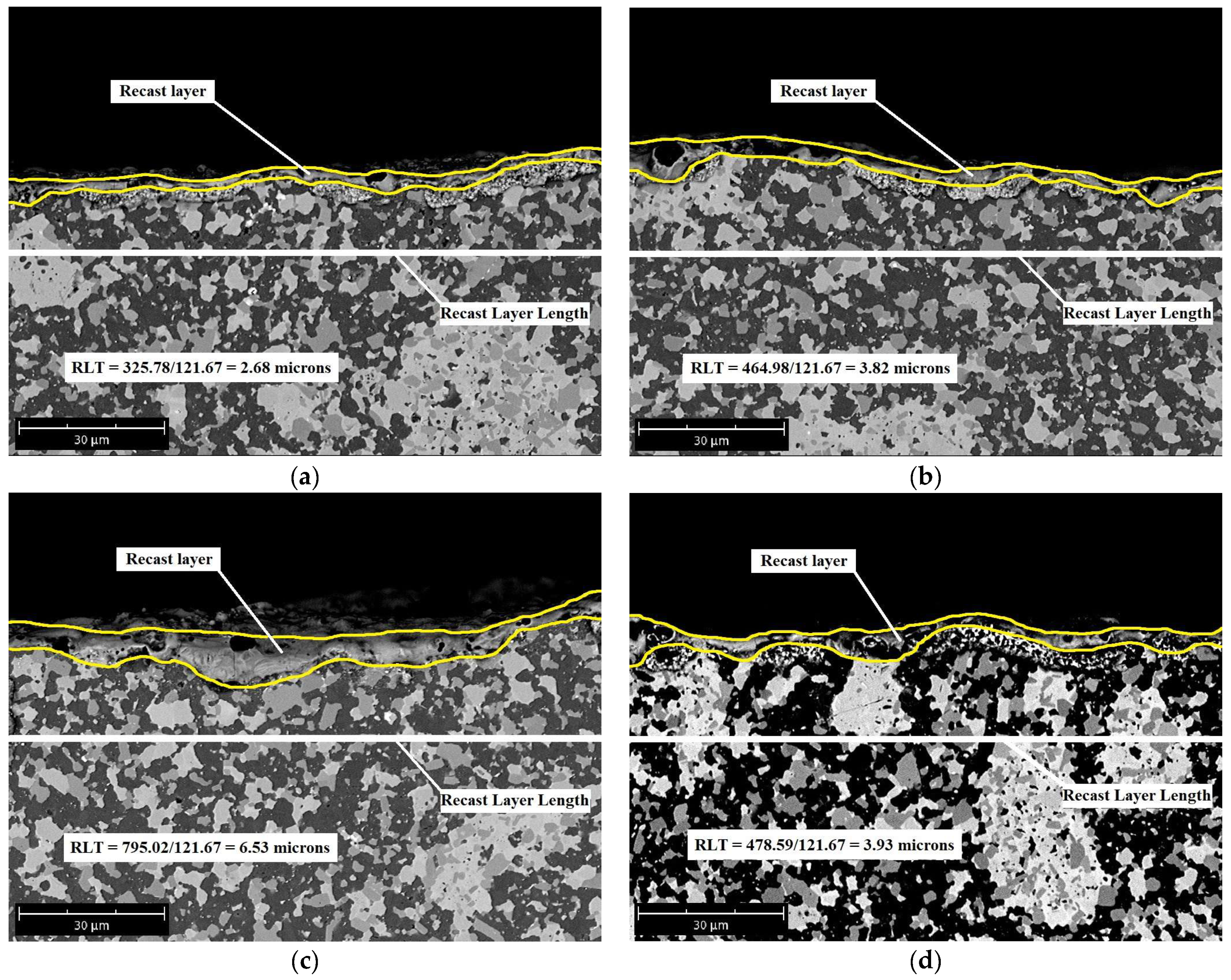
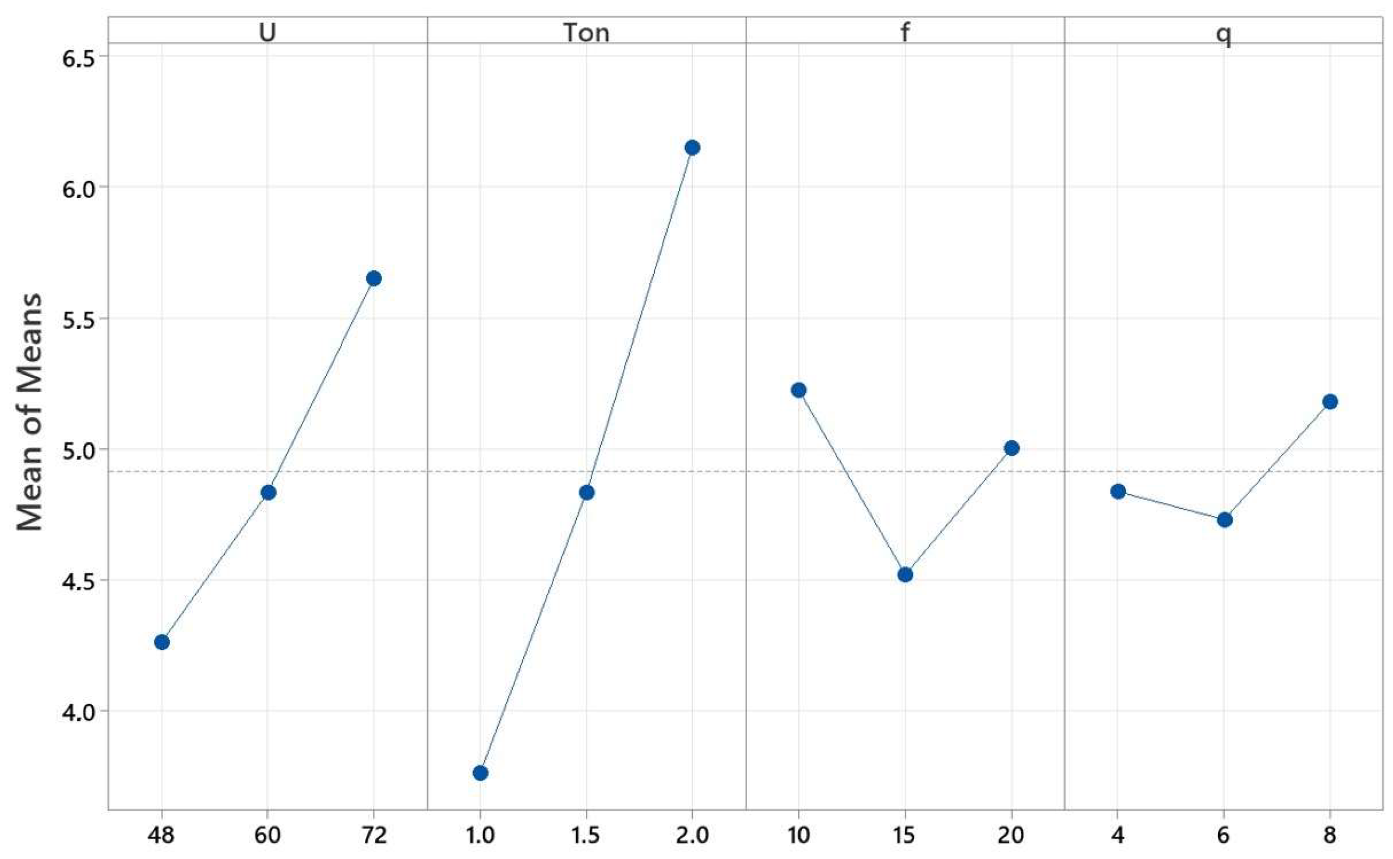
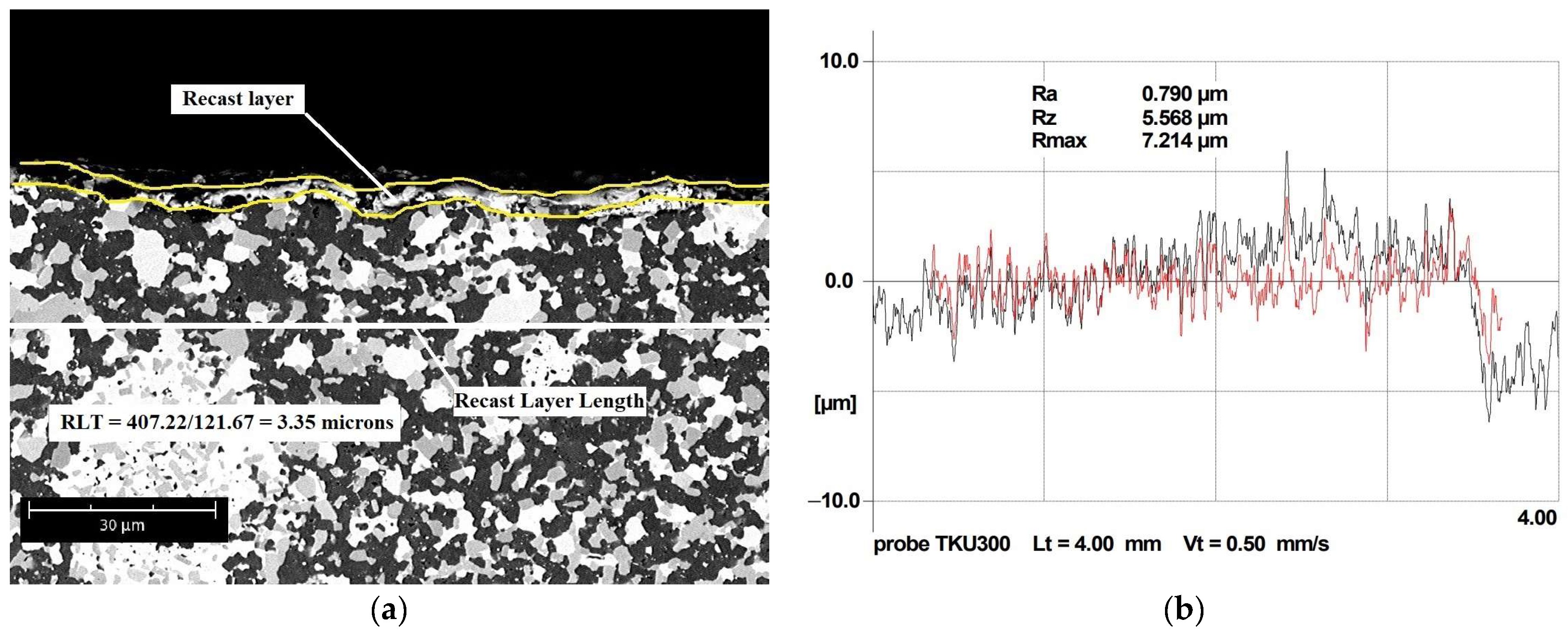
3.1. Parametric Effect on Recast Layer Thickness

The recast layer thickness was calculated using SEM images of nine different experimental results, as shown in Figure 2.
Table 4 shows the analysis of variance for recast layer thickness. Here, it can be seen that Ton was observed as the most significant process parameter, trailed by U, while Spark frequency and Wire speed had no significant effect on RLT. The contribution of Ton and U process parameters to RLT was 67.82% and 22.90%, respectively.
Analysis of variance was used to determine the regression coefficients of the model.
Equation (6) represents the regression model for RLT prediction at 95% CI in terms of significant process parameters.
RLT = −2.32 + 0.0578 U + 2.387 Ton.
Figure 3 shows the main effect plots for recast layer thickness, which describe the effect of process parameters on RLT.
This figure depicts an increasing trend for RLT when the Spark gap voltage and Pulse-on time increase from 48 to 72 V and from 1.0 to 2.0 µs, respectively. This increase in RLT can be explained by the higher discharge energy across the electrodes available to melt more material for the given U and Ton, which produces a significant increase in local heat generation, leading to further melting of the work material and, therefore, to a greater recast layer thickness. In this study, the thicker RLT (6.41 µm) was observed at U = 72V; Ton = 2.0 µs; f = 15 kHz; and q = 4 m/min, which corresponds to experiment 9. However, with the increase in Spark frequency from 10 to 15 kHz, a decrease in RLT was observed. This could be related to the effective flushing of eroded material at the given Spark frequency values. Then, an increase in RLT was noticed with increasing Spark frequency from 15 to 20 kHz. This may be related to the fact that at a higher Spark frequency, the pulse-off time is shorter and, therefore, the flushing time is also shorter, which reduces the spark gap since the debris formed cannot be easily removed [51,52]. This reduction in spark gap leads to a significant increase in spark intensity and ionization density in the spark zone, creating a significant increase in local heat generation, which forms a thicker RLT.
The values for pulse-off time (µs) can be easily calculated from Spark frequency using Equation (7):
Toff = (1/f) × 106 − Ton.
The Wire speed shows a mixed effect, but, in general, this factor does not have a significant influence on RLT, as has been confirmed in other works [53,54,55]. For instance, an increase in Wire speed (q) from 4 to 6 m/min results in a small decrease in RLT from 4.84 to 4.73 µm., while a further increase in q to 8 m/min leads to a small increase in RLT to 5.18 µm. A lower recast layer thickness (3.35 µm) was obtained at U = 48V; Ton = 1.0 µs; f = 10 kHz; and q = 4 m/min, which corresponds to experiment 1.

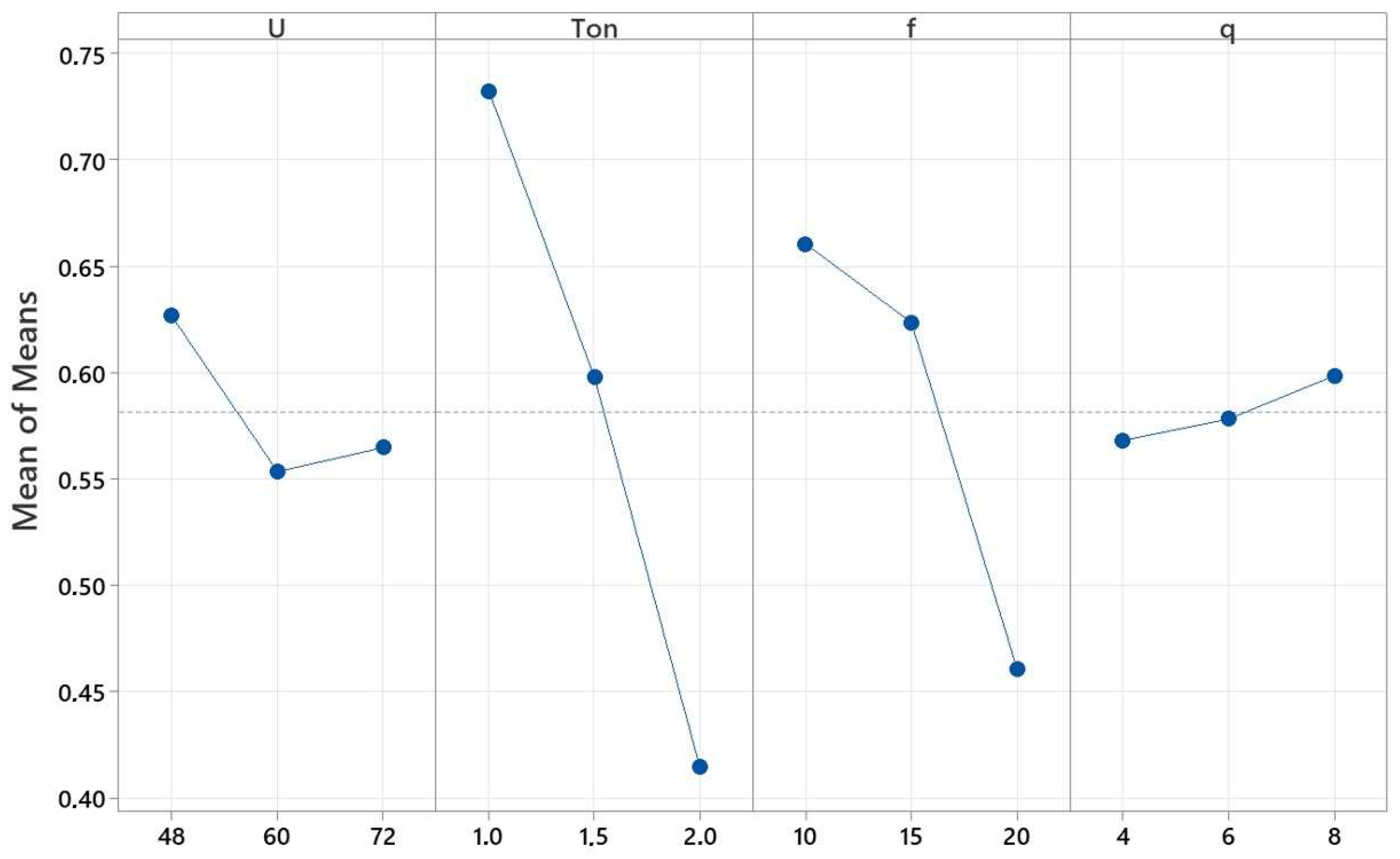
3.2. Parametric Effect on Surface Roughness

Table 5 shows the analysis of variance for surface roughness in this study. Here, it may seem that Spark frequency was determined as the most significant variable factor, followed by Pulse-on time and Spark gap voltage, while Wire speed had no significant effect on SR. From Table 5, it can be seen that the contribution of f, Ton, and U process parameters to SR were 56.24%, 19.42%, and 16.52%, respectively.
Analysis of variance was used to determine the regression coefficients of the model.
Equation (8) represents the regression model for SR prediction at 95% CI in terms of significant process parameters.
SR = 0.816 − 0.00487 U + 0.1267 Ton + 0.02157 f,
Figure 4 shows the main effect plots for surface roughness, which describe the effect of process parameters on it.
This figure shows that U, Ton, and f are the most influencing factors. In this study, the higher surface roughness (1.181 µm) was observed at U = 48V; Ton = 2.0 µs; f = 20 kHz; and q = 8 m/min, which corresponds to experiment 3. An increase in Spark gap voltage from 48 to 72 V results in a decreasing trend for SR. This may be related to the fact that the spark gap between the material’s surface and the electrode is regulated by the parameter U. Thus, when U is decreased, the spark gap between the work material’s surface and the electrode is also reduced, leading to a significant increase in ionization density and spark intensity in the spark gap. This effect causes a significant increase in local heat generation, which leads to further melting of the work material. Furthermore, the reduced spark gap prevents efficient flushing and allows the removal of only a small amount of molten material from the work zone. In addition, because the flushing time is reduced, the cooling time of the machined surface is also reduced, which leads to a noticeable increase in surface roughness. An increase in Ton from 1 to 2 µs results in deterioration of the surface quality (defined by roughness). This is because the increase in Ton leads to an increase in the discharge energy across the electrodes, which produces large vapor bubbles that collapse, producing large craters on the machined surface during the recrystallization process, which is in concordance with [56]. When Spark frequency is low, Toff increases, which facilitates the flushing of eroded material from the machined zone and reduces the SR [57]. On the other hand, when Spark frequency increases, a significant increase in surface roughness is observed. This is related to the decrease in Toff time, which increases the discharge energy and, at the same time, decreases the flushing and cooling time, which favors an increase in roughness. [58,59]. An increase in Wire speed from 4 to 6 m/min results in a small improvement in surface roughness (from 1.00 to 0.95 µm), which is in concordance with [43]. A further increase in speed from 6 to 8 m/min results in a small increase in surface roughness (from 0.95 to 0.96 µm). A lower surface roughness (0.79 µm) was obtained at U = 72V; Ton = 1.5 µs; f = 10 kHz; and q = 8 m/min, which corresponds to experiment 8.

3.3. Optimization Using Grey Relational Analysis

The obtained results of response parameters RLT and SR were normalized using Equation (2). After that, Equation (3) was used to calculate the deviation of each response parameter. Then, the grey relational coefficient was calculated using Equation (4). In this equation, coefficient ξ was considered to be 0.5. Next, the grey relational grade was estimated using Equation (5) and the calculated GRC for RLT and SR.
The rank of each experiment, based on the GRG value, is shown in Table 6. Here, it can be appreciated that experiment 1 shows the highest GRG value. This means that experiment 1 had the best multiple-run responses among the nine experiments performed. Second and third places in the rank are held by experiments 4 and 2, respectively.
Table 7 shows the tabulated responses of the average grey relational grade, calculated for the three levels of process variable factors. In this table, it can be observed that the maximum GRG of Spark gap voltage, Pulse-on time, Spark frequency, and Wire speed corresponds to levels 1, 1, 1, and 3, respectively.
Therefore, the optimal process parameter combination for the minimum RLT and SR was determined as U = 48 V; Ton = 1.0 µs; f = 10 kHz; and q = 8 m/min.
Figure 5 shows the main effect plots for GRG, which describe the effect of process parameters on it. Here, the dashed line represents the value corresponding to the total mean of GRG.

3.4. Confirmation Test

After identifying the optimal process parameter combination, confirmation experiments for prediction and validation were carried out. Thus, the predicted results were compared with the experimental findings obtained at the optimal process parameter combination. Predicted GRG (η) was calculated by using Equation (9) at the optimal process parameter combination [50,60].
G R G η = η m + i = 1 P η i η m ,
where ηm is the total mean of GRG, ηi = maximum of average GRG at the optimal level of process parameters, p = number of process parameters affecting responses = 4.
In this study, the ηm = 0.5816, p = 4, ηi (U) = 0.6265, ηi (Ton) = 0.7322, ηi (f) = 0.6604, ηi (q) = 0.5985. Thus, the predicted GRG (η) is:
GRG (η) = 0.5816 + (0.6265 − 0.5816) + (0.7322 − 0.5816) + (0.6604 − 0.5816) + (0.5985 − 0.5816) = 0.8729.
Figure 6 shows the SEM images of surfaces obtained using the optimized parameters and their respective profiles.
Table 8 shows the response values at the optimal process parameter combination and the initial process parameters. In GRA, the values of GRG near the mean line of the main effect plot are the initial process parameters (Figure 5). In Table 8, it can be seen that the RLT value was reduced from 5.61 µm to 3.16 µm, and the RS was reduced from 0.912 µm to 0.847 µm. In addition, it is observed that the experimental results agree with the predicted values, showing an increase in the GRC of 0.2756.

4. Conclusions

In this work, WEDM of SiC-TiB2-TiC electrically conductive ceramic composites was studied. For this, an orthogonal L9 Taguchi design was used. In addition, the influence of the process parameters on the RLT and SR response parameters was studied, and it was possible to identify, based on ANOVA, which process parameters were significant for each of the response parameters. Moreover, grey relational analysis was used to determine the combination of optimal process parameters in order to reach a lower recast layer thickness and surface roughness.
In general, the following conclusions can be made:
  • For recast layer thickness, the Pulse-on time was observed as the most significant process parameter, followed by Spark gap voltage. On the other hand, Spark frequency and Wire speed had no significance for RLT. An increasing trend for RLT was observed when the Spark gap voltage and Pulse-on time increased from 48 to 72 V and from 1.0 to 2.0 µs, respectively. Moreover, it has been noted that Spark frequency and Wire speed show a mixed effect. With the increase in Spark frequency from 10 to 15 kHz and Wire speed from 4 to 6 m/min, a decrease in RLT was observed. On the other hand, when Spark frequency and Wire speed increased from 15 to 20 kHz and from 6 to 8 m/min, respectively, an increase in RLT was noticed.
  • For surface roughness, Spark frequency was observed as the most significant process parameter, followed by Pulse-on time and Spark gap voltage. On the other hand, Wire speed had no significance for SR. A decrease in SR was observed with an increase in U. Moreover, it was noticed that SR decreased with a decrease in Pulse-on time and Spark frequency, while Wire speed showed a mixed effect. When Wire speed increased from 4 to 6 m/min, SR decreased from 1.00 to 0.95 µm. On the other hand, a further increase in speed results in a small increase in SR, from 0.95 to 0.96 µm.
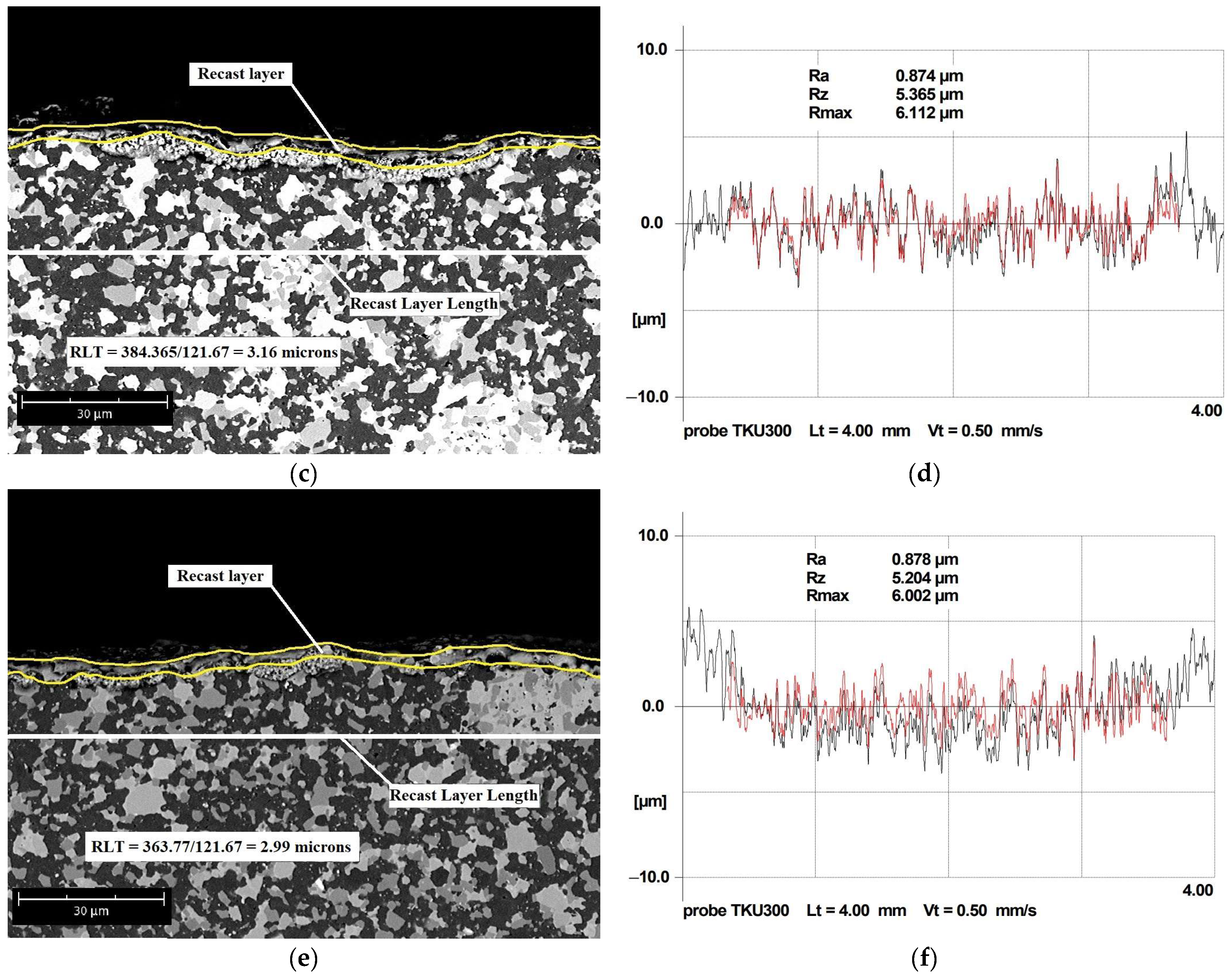
  • An RLT of 3.16 µm and an SR of Ra = 0.847 µm were obtained at optimal process parameters (U = 48V; Ton = 1.0 µs; f = 10 kHz; and q = 8 m/min). The RLT of 3.16 µm was the thinnest recast layer obtained.
  • Confirmation test showed that, in comparison to the initial machining conditions, WEDM of SiC-TiB2-TiC ceramic composite at optimal process parameters shows a decrease in RLT and SR by 43.67% and 7.12%, respectively.

Author Contributions

Conceptualization, N.W.S.P. and A.S.; methodology, N.W.S.P. and A.S.; software, A.M. and A.A.; formal analysis, Y.M. and A.M.; investigation, A.M.; resources, Y.P., N.P. and T.N.S.; data curation, N.W.S.P. and Y.P.; writing—original draft preparation, N.W.S.P. and A.S.; writing—review and editing, N.W.S.P. and A.S.; visualization, N.P., T.N.S. and Y.M.; supervision, A.A. and N.W.S.P.; project administration, S.N.G. and P.P.; funding acquisition, S.N.G. and P.P. All authors have read and agreed to the published version of the manuscript.

Funding

This work was supported financially by the Ministry of Science and Higher Education of the Russian Federation (project No. FSFS-2023-0003).

Institutional Review Board Statement

Not applicable.

Informed Consent Statement

Not applicable.

Data Availability Statement

Not applicable.

Acknowledgments

The work was carried out on the equipment of the Collective Use Center of MSTU “STANKIN” (project No. 075-15-2021-695).

Conflicts of Interest

The authors declare no conflict of interest.

Abbreviations

ANOVAAnalysis of variance,
B2O3Boron trioxide,
fSpark frequency,
GRAGrey relational analysis,
GRCGrey relational coefficient,
GRGGrey relational grade,
qWire speed,
RLARecast layer area,
RLLRecast layer length,
RLTRecast layer thickness,
SEMScanning electron microscope,
SiCSilicon carbide,
SRSurface roughness,
TiB2Titanium diboride,
TiCTitanium carbide,
TiO2Titanium dioxide,
ToffPulse-off time,
TonPulse-on time,
USpark gap voltage,
WEDMWire electrical discharge machining.

References

  1. Chen, J.; Li, W.; Jiang, W. Characterization of sintered TiC-SiC composites. Ceram. Int. 2009, 35, 3125–3129. [Google Scholar] [CrossRef]
  2. Cho, K.-S.; Kim, Y.-W.; Choi, H.-J.; Lee, J.-G. SiC-TiC and SiC-TiB2 composites densified by liquid-phase sintering. J. Mater. Sci. 1996, 31, 6223–6228. [Google Scholar] [CrossRef]
  3. Shaffer, P.T.B. The SiC phase in the system SiC-B4C-C. Mater. Res. Bull. 1969, 4, 213–219. [Google Scholar] [CrossRef]
  4. Lee, S.-K.; Ishida, W.; Lee, S.-Y.; Nam, K.-W.; Ando, K. Crack-healing behavior and resultant strength properties of silicon carbide ceramic. J. Eur. Ceram. Soc. 2005, 25, 569–576. [Google Scholar] [CrossRef]
  5. Grigoriev, S.N.; Pristinskiy, Y.; Soe, T.N.; Malakhinsky, A.; Mosyanov, M.; Podrabinnik, P.; Smirnov, A.; Solís Pinargote, N.W. Processing and Characterization of Spark Plasma Sintered SiC-TiB2-TiC Powders. Materials 2022, 15, 1946. [Google Scholar] [CrossRef]
  6. Song, Y.L.; Pan, C.Z.; Zhang, J.; Zhu, B. TiB2-TiC-SiC composites prepared through high-gravity field activated SHS. IOP Conf. Ser. Mater. Sci. Eng. 2018, 382, 022048. [Google Scholar] [CrossRef]
  7. Li, W.-J.; Tu, R.; Goto, T. Preparation of TiC-TiB2-SiC Ternary Eutectic Composites by Arc-Melting and Their Characterizations. Mater. Trans. 2006, 47, 1193–1197. [Google Scholar] [CrossRef]
  8. Mestral, F.; Thevenot, F. Ceramic composites: TiB2-TiC-SiC. Part I Properties and microstructures in the ternary system. J. Mater. Sci. 1991, 26, 5547–5560. [Google Scholar] [CrossRef]
  9. Somiya, S. Handbook of Advanced Ceramics. Materials, Applications, Processing, and Properties, 2nd ed.; Somiya, S., Ed.; Academic Press: Cambridge, MA, USA, 2013. [Google Scholar] [CrossRef]
  10. Grigoriev, S.; Vereschaka, A.; Milovich, F.; Tabakov, V.; Sitnikov, N.; Andreev, N.; Sviridova, T.; Bublikov, J. Investigation of multicomponent nanolayer coatings based on nitrides of Cr, Mo, Zr, Nb, and Al. Surf. Coat. Technol. 2020, 401, 126258. [Google Scholar] [CrossRef]
  11. Vereschaka, A.S.; Grigoriev, S.N.; Sotova, E.S.; Vereschaka, A.A. Improving the effi-ciency of the cutting tools made of mixed ceramics by applying modifying nano-scale multilayered coatings. Adv. Mat. Res. 2013, 712–715, 391–394. [Google Scholar] [CrossRef]
  12. Akhtar, S.S. A critical review on self-lubricating ceramic-composite cutting tools. Ceram. Int. 2021, 47, 20745–20767. [Google Scholar] [CrossRef]
  13. Wäsche, R.; Klaffke, D. In situ formation of tribologically effective oxide interfaces in SiC-based ceramics during dry oscillating sliding. Tribol. Lett. 1998, 5, 173–190. [Google Scholar] [CrossRef]
  14. Wäsche, R.; Yarim, R.; Klaffke, D.; Hartelt, M. Oscillating sliding wear behaviour of SiC, TiC, TiB2, 59SiC-41TiB2 and 52SiC-24TiC-24TiB2 materials up to 750 °C in air. Tribotest 2006, 12, 99–111. [Google Scholar] [CrossRef]
  15. Fattahi, M.; Pazhouhanfar, Y.; Delbari, S.A.; Shaddel, S.; Sabahi Namini, A.; Shahedi Asl, M. Influence of TiB2 content on the properties of TiC-SiCw composites. Ceram. Int. 2019, 46, 7403–7412. [Google Scholar] [CrossRef]
  16. Shahedi Asl, M.; Delbari, S.A.; Shayesteh, F.; Ahmadi, Z.; Motallebzadeh, A. Reactive Spark plasma sintering of TiB2–SiC–TiN novel composite. Int. J. Refract. Met. Hard Mater. 2019, 81, 119–126. [Google Scholar] [CrossRef]
  17. Mestral, F.; Thevenot, F. Ceramic composites: TiB2-TiC-SiC. J. Mater. Sci. 1991, 26, 5561–5565. [Google Scholar] [CrossRef]
  18. Luzhkova, A.P.; Boikov, S.Y.; Ordanyan, S.S.; Rumyantsev, V.I. Carbothermal synthesis of the SiC-TiC-TiB2 eutectic system, mechanical properties of the SiC-TiC-TiB2 material based on submicron powders with a nanoscale component. In Proceedings of the Rusnanotech 2011. IV Nanotechnology International Forum, Moscow, Russia, 26–28 October 2011. [Google Scholar]
  19. Sun, P.Q.; Zhu, D.G.; Jiang, X.S.; Sun, H.L.; Xia, Z.H. Research on Microstructures and Properties of in-situ Synthesis of TiB2-TiC0.8-SiC Multiphase Ceramics. J. Inorg. Mater. 2013, 28, 363–368. [Google Scholar] [CrossRef]
  20. Cai, X.Q.; Wang, D.P.; Wang, Y.; Yang, Z.W. Microstructural evolution and mechanical properties of TiB2-TiC-SiC ceramics joint brazed using Ti-Ni composite foils. J. Eur. Ceram. Soc. 2020, 40, 3380–3390. [Google Scholar] [CrossRef]
  21. Zhang, G.J.; Yue, X.M.; Jin, Z.Z. Preparation and microstructure of TiB2-TiC-SiC platelet-reinforced Ceramics by reactive hot-pressing. J. Eur. Ceram. Soc. 1996, 16, 1145–1148. [Google Scholar] [CrossRef]
  22. Zhao, G.; Huang, C.; He, N.; Liu, H.; Zou, B. Microstructure and mechanical properties at room and elevated temperatures of reactively hot pressed TiB2-TiC-SiC composite ceramic tool materials. Ceram. Int. 2016, 42, 5353–5361. [Google Scholar] [CrossRef]
  23. Zhao, G.; Huang, C.; He, N.; Liu, H.; Zou, B. Fabrication and cutting performance of reactively hot-pressed TiB2-TiC-SiC ternary cutting tool in hard turning of AISI H13 steel. Int. J. Adv. Manuf. Technol. 2016, 91, 943–954. [Google Scholar] [CrossRef]
  24. Tu, R.; Li, W.; Goto, T. Phase Orientation of a TiC-TiB2-SiC Ternary Eutectic Composite Prepared by An FZ Method. Mater. Sci. Forum 2007, 534–536, 1057–1060. [Google Scholar] [CrossRef]
  25. Danilovich, D.P. Ceramic Matrix Materials in the SiC-TiB2-(TiC, B4C, AlN) System. Ph.D. Thesis, St. Petersburg State Institute of Technology, St. Petersburg, Russia, 4 June 2019. Available online: http://old.technolog.edu.ru/university/dissovet/autoreferats/file/6581-..html (accessed on 12 September 2023).
  26. Taki, Y.; Kitiwan, M.; Katsui, H.; Goto, T. Electrical and thermal properties of off-stoichiometric SiC prepared by Spark plasma sintering. J. Asian Ceram. Soc. 2018, 6, 95–101. [Google Scholar] [CrossRef]
  27. Malik, R.; Kim, Y.-W. Plastic deformation-induced improved mechanical and thermal properties in hot-forged SiC-TiC composite. J. Eur. Ceram. Soc. 2021, 41, 6223–6228. [Google Scholar] [CrossRef]
  28. Cho, K.S. Microstructure and Fracture Toughness of In-situ Toughened SiC-TiC Composites. J. Mater. Sci. Lett. 1998, 17, 1081–1084. [Google Scholar] [CrossRef]
  29. Ohya, Y.; Hoffmann, M.J.; Petzow, G. Sintering of in-Situ Synthesized SiC-TiB2 Composites with Improved Fracture Toughness. J. Am. Ceram. Soc. 1992, 75, 2479–2483. [Google Scholar] [CrossRef]
  30. Zou, B.; Huang, C.; Song, J.; Liu, Z.; Liu, L.; Zhao, Y. Mechanical properties and microstructure of TiB2-TiC composite ceramic cutting tool material. Int. J. Refract. Met. Hard Mater. 2012, 35, 1–9. [Google Scholar] [CrossRef]
  31. Gutiérrez-González, C.F.; Pozhidaev, S.; Rivera, S.; Peretyagin, P.; Solís, W.; Díaz, L.A.; Fernández, A.; Torrecillas, R. Longer-lasting Al2O3-SiCw-TiC cutting tools obtained by Spark plasma sintering. Int. J. Appl. Ceram. Technol. 2017, 14, 367–373. [Google Scholar] [CrossRef]
  32. Pristinskiy, Y.; Pinargote, N.W.S.; Smirnov, A. The effect of MgO addition on the microstructure and mechanical properties of alumina ceramic obtained by Spark plasma sintering. Mater. Today Proc. 2019, 19, 1990–1993. [Google Scholar] [CrossRef]
  33. Pristinskiy, Y.; Pinargote, N.W.S.; Smirnov, A. Spark plasma and conventional sintering of ZrO2-TiN composites: A comparative study on the microstructure and mechanical properties. MATEC Web Conf. 2018, 224, 01055. [Google Scholar] [CrossRef]
  34. Clijsters, S.; Liu, K.; Reynaerts, D.; Lauwers, B. EDM technology and strategy development for the manufacturing of complex parts in SiSiC. J. Mater. Process. Technol. 2010, 210, 631–641. [Google Scholar] [CrossRef]
  35. Sharma, A.; Babbar, A.; Tian, Y.; Pathri, B.P.; Gupta, M.; Singh, R. Machining of ceramic materials: A state-of-the-art review. Int. J. Interact. Des. Manuf. 2022, 1–21. [Google Scholar] [CrossRef]
  36. Schüler, M.; Herrig, T.; Bergs, T. A study on abrasive waterjet multi-stage machining of ceramics. Procedia CIRP 2022, 108, 770–775. [Google Scholar] [CrossRef]
  37. Ma, Z.; Wang, Q.; Liang, Y.; Cui, Z.; Meng, F.; Chen, L.; Wang, Z.; Yu, T.; Liu, C. The mechanism and machinability of laser-assisted machining zirconia ceramics. Cer. Int. 2023, 49, 16971–16984. [Google Scholar] [CrossRef]
  38. Grigoriev, S.N.; Nadykto, A.B.; Volosova, M.A.; Zelensky, A.A.; Pivkin, P.M. WEDM as a Replacement for Grinding in Machining Ceramic Al2O3-TiC Cutting Inserts. Metals 2021, 11, 882. [Google Scholar] [CrossRef]
  39. Grigoriev, S.N.; Hamdy, K.; Volosova, M.A.; Okunkova, A.A.; Fedorov, S.V. Electrical discharge machining of oxide and nitride ceramics: A review. Mater. Des. 2021, 209, 109965. [Google Scholar] [CrossRef]
  40. Pramanick, A.; Mandal, S.; Dey, P.; Das, P.K. WEDM process optimization of sintered structural ceramic sample by using fuzzy-MPCI technique. Mater. Today Proc. 2021, 41, 925–993. [Google Scholar] [CrossRef]
  41. Grigoriev, S.N.; Volosova, M.A.; Okunkova, A.A.; Fedorov, S.V.; Hamdy, K.; Po-drabinnik, P.A.; Pivkin, P.M.; Kozochkin, M.P.; Porvatov, A.N. Electrical Discharge Ma-chining of Oxide Nanocomposite: Nanomodification of Surface and Subsurface Layers. J. Manuf. Mater. Process. 2020, 4, 96. [Google Scholar] [CrossRef]
  42. Bains, P.S.; Sidhu, S.S.; Payal, H.S.; Kaur, S. Magnetic Field Influence on Surface Modifications in Powder Mixed EDM. Silicon 2019, 11, 415–423. [Google Scholar] [CrossRef]
  43. Bisaria, H.; Shandilya, P. The machining characteristics and surface integrity of Ni-rich NiTi shape memory alloy using wire electric discharge machining. Proc. Inst. Mech. Eng. Part C J. Mech. Eng. Sci. 2019, 233, 1068–1078. [Google Scholar] [CrossRef]
  44. Singh, S.; Yeh, M.F. Optimization of Abrasive Powder Mixed EDM of Aluminum Ma-trix Composites with Multiple Responses Using Gray Relational Analysis. J. Mater. Eng. Perform. 2012, 21, 481–491. [Google Scholar] [CrossRef]
  45. Kuo, Y.; Yang, T.; Huang, G.-W. The use of grey relational analysis in solving multiple attribute decision-making problems. Comput. Ind. Eng. 2008, 55, 80–93. [Google Scholar] [CrossRef]
  46. Girish, B.M.; Siddesh, H.S.; Satish, B.M. Taguchi grey relational analysis for parametric optimization of severe plastic deformation process. SN Appl. Sci. 2019, 1, 937. [Google Scholar] [CrossRef]
  47. Deng, J.; Yan, Q.; Lu, J.; Xiong, Q.; Pan, J. Optimisation of Lapping Process Parameters for Single-Crystal 4H–SiC Using Orthogonal Experiments and Grey Relational Analysis. Micromachines 2021, 12, 910. [Google Scholar] [CrossRef]
  48. Suresh Kumar, S.; Uthayakumar, M.; Thirumalai Kumaran, S.; Parameswaran, P.; Mohandas, E.; Kempulraj, G.; Ramesh Babu, B.S.; Natarajan, S.A. Parametric op-timization of wire electrical discharge machining on aluminium based composites through. grey relational analysis. J. Manuf. Process. 2015, 20, 33–39. [Google Scholar] [CrossRef]
  49. Huang, J.T.; Liao, Y.S. Optimization of machining parameters of Wire-EDM based on Grey relational and statistical analyses. Int. J. Prod. Res. 2003, 41, 1707–1720. [Google Scholar] [CrossRef]
  50. Sylajakumari, P.A.; Ramakrishnasamy, R.; Palaniappan, G. Taguchi grey relational analysis for multi-response optimization of wear in co-continuous composite. Materials 2018, 11, 1743. [Google Scholar] [CrossRef]
  51. Tan, P.C.; Yeo, S.H. Investigation of recast layers generated by a powder-mixed die-lectric micro electrical discharge machining process. Proc. Inst. Mech. Eng. Part B J. Eng. Manuf. 2011, 225, 1051–1062. [Google Scholar] [CrossRef]
  52. Wu, K.L.; Yan, B.H.; Huang, F.Y.; Chen, S.C. Improvement of surface finish on SKD steel using electro-discharge machining with aluminum and surfactant added dielectric. Int. J. Mach. Tools Manuf. 2005, 45, 1195–1201. [Google Scholar] [CrossRef]
  53. Kumar, A.; Kumar, V.; Kumar, J. Surface crack density and recast layer thickness analysis in WEDM process through response surface methodology. Mach. Sci. Technol. 2016, 20, 201–230. [Google Scholar] [CrossRef]
  54. Krishna Mussada, E.; Chee Hua, C.; Kameswari Prasada Rao, A. Surface hardenability studies of the die steel machined by WEDM. Mater. Manuf. Process. 2018, 33, 1745–1750. [Google Scholar] [CrossRef]
  55. Sharma, P.; Chakradhar, D.; Narendranath, S. Measurement of WEDM per-formance characteristics of aero-engine alloy using RSM-based TLBO algorithm. Measurement 2021, 179, 109483. [Google Scholar] [CrossRef]
  56. Marelli, D.; Singh, S.K.; Nagari, S.; Subbiah, R. Optimisation of machining parameters of wire-cut EDM on super alloy materialsea review. Mater. Today Proc. 2020, 26, 1021e1027. [Google Scholar] [CrossRef]
  57. Ahuja, N.; Batra, U.; Kumar, K. Experimental investigation and optimization of wire electrical discharge machining for surface characteristics and corrosion rate of biode-gradable Mg alloy. J. Mater. Eng. Perform. 2020, 29, 4117e4129. [Google Scholar] [CrossRef]
  58. Sharma, N.; Raj, T.; Jangra, K.K. Parameter optimization and experimental study on wire electrical discharge machining of porous Ni40Ti60 alloy. Proc. Inst. Mech. Eng. Part B J. Eng. Manuf. 2015, 231, 6. [Google Scholar] [CrossRef]
  59. Manjaiah, M.; Narendranath, S.; Basavarajappa, S.; Gaitonde, V. Investigation on materi-al removal rate, surface and subsurface characteristics in wire electro discharge Machin-ing of Ti50Ni50-xCux shape memory alloy. Proc. Inst. Mech. Eng. Part L J. Mater. Des. Appl. 2015, 232, 2. [Google Scholar] [CrossRef]
  60. Meena, V.K.; Azad, M.S. Grey relational analysis of micro-EDM machining of Ti-6Al-4V alloy. Mater. Manuf. Process. 2012, 27, 973–977. [Google Scholar] [CrossRef]
Figure 1. The applied force, temperature (a), and punch displacement (b) schedules in Spark plasma sintering.
Coatings 13 01728 g001
Figure 2. Recast layer thickness for L9 different experimental runs. The units of U, Ton, f, and q were V, µs, kHz, and m/min, respectively. (a) Experiment 1: U = 48; Ton = 1.0; f = 10; q = 4; (b) Experiment 2: U = 48; Ton = 1.5; f = 15; q = 6; (c) Experiment 3: U = 48; Ton = 2.0; f = 20; q = 8; (d) Experiment 4: U = 60; Ton = 1.0; f = 15; q = 8; (e) Experiment 5: U = 60; Ton = 1.5; f = 20; q = 4; (f) Experiment 6: U = 60; Ton = 2.0; f = 10; q = 6; (g) Experiment 7: U = 72; Ton = 1.0; f = 20; q = 6; (h) Experiment 8: U = 72; Ton = 1.5; f = 10; q = 8; (i) Experiment 9: U = 72; Ton = 2.0; f = 15; q = 4.
Coatings 13 01728 g002aCoatings 13 01728 g002b
Figure 3. Main effect plots for recast layer thickness.
Coatings 13 01728 g003
Figure 4. Main effect plots for surface roughness.
Coatings 13 01728 g004
Figure 5. Main effect plots for GRG.
Coatings 13 01728 g005
Figure 6. Experimental optimal process (U = 48; Ton = 1.0; f = 10; q = 8): (a,c,e)—SEM images of RLT for replicates 1, 2, and 3; and (b,d,f)—surface roughness of RLT shown in (a,c,e), respectively.
Coatings 13 01728 g006aCoatings 13 01728 g006b
Table 1. Specifications of WEDM machine and properties of SiC-TiB2-TiC ceramic composite.
Specifications of WEDM MachineProperties of SiC-TiB2-TiC [5]
MachineArta 123 PROTheoretical density3.79 g/cm3
Circuit voltage220 V, 50 HzRelative density98.99%
Dielectricdeionized waterThermal diffusivity at 1000 °C13 mm2/s
Pulse-on time0.3–2.7 µsHardness22.28 GPa
Spark frequency1–35 kHzElectrical conductivity5.6 S/cm
Electrodebrass wire (∅ 0.25 mm)Bending strength540 MPa
Wire speed1–14 m/minFracture toughness6.2 MPa·m1/2
Spark gap voltage24–108 V
Table 2. Values of variable WEDM process parameters used in this study.
Levels
Factor/UnitsSymbol123
Spark gap voltage (V)U486072
Pulse-on time (µs)Ton11.52
Spark frequency (kHz)f101520
Wire speed (m/min)q468
Table 3. L9 Taguchi orthogonal design with experimental responses.
Exp. No.Process ParametersResponse Parameters
U (V)Ton (µs)f (kHz)q (m/min)RLT (µm)SR (µm)
1481.01043.350.883
2481.51563.610.982
3482.02085.871.181
4601.01583.560.900
5601.52044.771.152
6602.01066.210.935
7721.02064.410.928
8721.51086.160.794
9722.01546.420.973
Table 4. ANOVA for recast layer thickness.
SourceDFSSMSF-Valuep-Value% Contr.
Regression411.67792.9194912.700.01592.70
U12.88432.8842712.540.024 #22.90
Ton18.54438.5442737.150.004 #67.82
f10.07260.072600.320.604 *0.58
q10.17680.176820.770.430 *1.40
Error40.91990.22997 7.30
Total812.5978 100.00
R-sq = 92.70%, R-sq (Adj.) = 85.40%, R-sq (pred.) = 39.67%
DF—degrees of freedom, SS—sum of square, MS—mean square, F-value—Fischer value, p-value—probability value, % Contr.—% contribution, #—significant, and *—nonsignificant.
Table 5. ANOVA for surface roughness.
SourceDFSSMSF-Valuep-Value% Contr.
Regression40.11730.0293317.300.00994.52
U10.02050.0205312.120.025 #16.52
Ton10.02410.0240714.200.020 #19.42
f10.06980.0697741.160.003 #56.24
q10.00290.002951.740.258 *2.34
Error40.00680.00169 5.48
Total80.1241 100.00
R-sq = 94.54%, R-sq (Adj.) = 89.07%, R-sq (pred.) = 80.15%
DF—degrees of freedom, SS—sum of square, MS—mean square, F-value—Fischer value, p-value—probability value, % Contr.—% contribution, #—significant, and *—nonsignificant.
Table 6. Grey relational analysis.
Exp.NormalizedDeviationGRCGRGRank
NoRLTSRRLTSRRLTSR
11.00000.77000.00000.23001.00000.68500.84251
20.91530.51420.08470.48580.85520.50720.68123
30.17920.00000.82081.00000.37850.33330.35599
40.93160.72610.06840.27390.87970.64610.76292
50.53750.07490.46250.92510.51950.35090.43527
60.06840.63050.93160.36950.34930.57500.46216
70.65470.65370.34530.34630.59150.59080.59125
80.08471.00000.91530.00000.35331.00000.67664
90.00000.53751.00000.46250.33330.51950.42648
Table 7. Response for the average GRG.
LevelUTonfq
10.62650.73220.66040.5680
20.55340.59770.62350.5782
30.56470.41480.46080.5985
Delta0.07310.31740.19960.0304
Rank3124
Total mean of GRG = 0.5816.
Table 8. Confirmation test.
ParametersInitial Process ParametersOptimal Process Parameters
PredictedExperimental
Combination Level(U)3(Ton)2(f)2(q)2(U)1(Ton)1(f)1(q)3(U)1(Ton)1(f)1(q)3
RLT5.613.313.16
SR0.9120.8360.847
GRG0.61940.87290.8925
Improvement in GRG = 0.8925 − 0.6194 = 0.2756.
Disclaimer/Publisher’s Note: The statements, opinions and data contained in all publications are solely those of the individual author(s) and contributor(s) and not of MDPI and/or the editor(s). MDPI and/or the editor(s) disclaim responsibility for any injury to people or property resulting from any ideas, methods, instructions or products referred to in the content.

