Article

Optimizing Friction Welding Parameters in AISI 304 Austenitic Stainless Steel and Commercial Copper Dissimilar Joints

by
R. Paventhan
1,
D. Thirumalaikumarasamy
2,*,
Venkata Charan Kantumuchu
3,
Omar Shabbir Ahmed
4,
Mohamed Abbas
5,6,
Ahmad Aziz Alahmadi
7,
Mamdooh Alwetaishi
8,
Ali Nasser Alzaed
9 and
Chidambaram Seshadri Ramachandran
10
1
Dhanalakshmi Srinivasan College of Engineering, Mahabalipuram, Chennai 603104, India
2
Department of Mechanical Engineering, Government College of Engineering, Bargur 635104, India
3
Global Quality Director, Manufacturing Department, Bradley University, Peoria, IL 61625, USA
4
Engineering Management Department, College of Engineering, Prince Sultan University, Riyadh 11586, Saudi Arabia
5
Electrical Engineering Department, College of Engineering, King Khalid University, Abha 61421, Saudi Arabia
6
Electronics and Communications Department, College of Engineering, Delta University for Science and Technology, Gamasa 35712, Egypt
7
Department of Electrical Engineering, College of Engineering, Taif University, P.O. Box 11099, Taif 21944, Saudi Arabia
8
Department of Civil Engineering, College of Engineering, Taif University, Taif 21974, Saudi Arabia
9
Department of Architecture Engineering, College of Engineering, Taif University, P.O. Box 11099, Taif 21944, Saudi Arabia
10
Department of Materials Science and Engineering, Stony Brook University, Stony Brook, NY 11794, USA
*
Author to whom correspondence should be addressed.
Coatings 2023, 13(2), 261; https://doi.org/10.3390/coatings13020261
Submission received: 28 November 2022 / Revised: 25 December 2022 / Accepted: 13 January 2023 / Published: 22 January 2023

Abstract

:
By using fusion welding to weld AISI 304 austenitic stainless steel (ASS) and commercial copper, the creation of brittle intermetallic in the weld region that compromises the strength of the joints is the primary challenge. However, friction welding is a suitable method for joining these two materials because no obvious defects are produced at the joints. The joint strength is significantly influenced by the friction-welding-process variables including the pressure of friction, pressure of forging, time of friction, and time of forging. Throughout this study, a central composite factorial design-based empirical relationship-building effort was carried out to determine the tensile strengths of friction-welded AISI 304 austenitic stainless steels (ASS) and commercial copper alloys dissimilar joints from the process variables. The process conditions were optimized employing response surface methods in order to attain the joint’s optimum tensile strength. This research revealed that the greatest tensile strength of the joint created with the friction pressure of 60 MPa, forging pressure of 60 MPa, friction duration of 4 s, and forging time of 4 s, correspondingly, was 489 MPa. As a result, the intermetallic formation at the interface could be identified.

1. Introduction

Dissimilar materials welding is a remarkable technique that offers numerous advantages, including the ability to combine various qualities into a single component, create lightweight structures, reduce overall costs, and improve efficiency through creative engineering approaches [1,2,3]. One of these material combinations with different physical, chemical, and thermal properties is copper (Cu) and stainless steel (ASS) [4,5,6,7]. Nevertheless, welding of Cu-SS is a considerable area of interest owing to the advantages of having separate thermal performance at both ends, cost savings, enhancement of the mechanical and thermal efficiency of heat exchangers, and other novel applications that are innovative. The differences in metallurgical characteristics make the welding of the Cu-SS combination difficult, notwithstanding the attractive engineering solutions and subsequent applications. Traditional fusion welding techniques are insufficient to provide strong, error-free welds because of the significant challenges involved in welding this dissimilar combination Cu-ASS joint [8,9]. Owing to metallurgical incompatibility, significant melting point differences, thermal mismatches, and other considerations, conventional fusion welding of numerous of these incompatible metal combinations is not practicable. In these circumstances, solid-state welding procedures that restrict the amount of intermixing are typically employed. One such popular solid-state welding approach in these circumstances is friction welding. [10,11].
To prevent unintentional heating of the entire component, copper and iron-based alloys are employed as cooling tubes [12]. Aluminium/copper and steel are connected in a number of equipment components employed in the automation sector, notably electro-hydraulic linear actuators with control systems. Aluminum/copper is utilized to address electrical conductivity, while steel is applied for strength and wear resistance [13]. The limited solubility of copper and iron as well as the absence of any intermetallic compounds makes copper-steel couples unique [14]. Pipelines composed of copper alloys often operate at temperatures much below 150–300 °C [15]. Within such a range of temperature, there are considerable variations in the impacts seen in copper alloys when exposed to radiation. As a consequence, at a temperature of 150 °C, low-temperature radiation embrittlement can be seen [16]. There are softening effects when irradiation temperatures are between 300 and 400 °C [17,18].
A study on continual drive friction welding for T2 Cu to 1Cr18Ni9Ti SS materials with a 30 mm solid rod diameter was performed by FU et al. [19]. Through processing friction welding with an additional electric field, researchers were able to attain the greatest torsional strength. According to Reza et al. [20], the development of a vortex-shaped joint interface was triggered by an increase in the standoff distance and explosive material thickness, and localized melted areas were created as a consequence of an improvement in the collision pressure close to the interface vortex waves. Through using friction welding, Shanjeevi et al. [21] examined the mechanical and metallurgical characteristics of different materials. Continuous drive friction welding on cylindrical rods was used by Jayabharath et al. [22] to create dissimilar junctions between steel (made using powder metallurgy) and economically efficient wrought copper materials. By adjusting the friction-welding-process parameters, they evaluated various processing scenarios and proposed a number of parametric combinations that improved joint qualities. Kimura et al. [23] investigated the dissimilar joints of oxygen-free copper to low carbon steel materials on cylindrical rods employing continual drive friction welding. They looked at how friction duration and forge pressure affected joint efficiency. According to Mohammad Reza Jandaghi et al. [24], the exceptional kinetic energy of the impact resulted in a greater standoff distance leading to an increase in the corrosion potential, current rate, and concentration gradient at the interface, which diminished resistance to corrosion. Ambroziak et al. explored friction welding for different metal of copper to austenitic steel and copper to titanium zirconium molybdenum alloy welds employing a cylindrical rod design [25]. In the joint between the copper and austenitic steel, they saw a micro-crack close to the flaying surface toward the copper substrate. Friction welding was used by Yeoh et al. [26] to combine incompatible materials such as copper C1100 and AISI 1030 steel using a cylindrical solid bar. Wang et al. [27] explored inertia radial friction welding for the dissimilar welding of a copper ring on a 35-CrMnSi steel rod. In that other research of radial friction welding between H90 brass and D60 steel materials by Luo et al. [28], the welding is performed on a steel tube with a brass ring on it. Along with the diffusion evidence in other areas of the contact, they noticed tiny flaws around the welding interface. According to SafaraliFeleh Shargh et al. [29], raising the temperature and duration of the process of heat treatment at the specimen interfaces tends to decrease the energy stored during explosive welding, the distinction in the concentration of aluminium when compared to steel in the interface layer, the rate of corrosion (current density), and the electrical charge transfer. In order to investigate dissimilar welding between H21 steel and copper alloy of 1015, Sahin et al. [30] coupled friction welding with a heat transmission mechanism. To forecast the variation in heat transfer as well as a modification in the process parameters, they created a two-dimensional heat transfer concept that is transitory. The inertia radial friction welding for H90 brass-D60 steel connections was researched through Luo et al. [31]. According to the authors, following welding, a microstructure made up of bainite and martensite develops in the thermomechanical affected zone (TMAZ), and as a result, the faying zone’s microhardness is raised.
This literature review reveals that the phase development at the interface, microhardness changes, evaluation of tensile properties, and microstructural characteristics dominated information published on friction welding of dissimilar materials. The friction input variables have not yet been systematically studied to achieve the highest tensile strength in dissimilar junctions made of copper and stainless steel. Therefore, this research attempted to optimize the friction-welding-process variables to achieve the greatest tensile strength in copper and stainless steel (ASS) dissimilar joints.

2. Experimental Work

2.1. Materials and Methods

The investigation’s base materials were 75 mm-long, cylinder-shaped rods of copper alloy (Cu) and AISI 304 austenitic stainless steel (ASS). Table 1 and Table 2 provide the composition of the chemical and mechanical characteristics of the materials. In friction welding experiments, the SS material (ASS) was clamped to a rotating three-jaw chuck, whereas the circumference clamping on the Cu pipe was connected to other extremities that do not move but retain the work piece firmly. On a specialized hydraulic-controlled, continual drive friction welding equipment, the welding experiments were carried out (20 kN capacity). Prior to choosing the process inputs for the current inquiry, feasibility tests were performed based on firsthand knowledge.
The preset values of the various variables were employed to alter the process parameters in the friction welding equipment. The welded samples were tested and characterized after welding to be able to assess the characteristics and microstructures of the joint. On welded samples, various inspection techniques were used, including visual inspection, tensile testing with fracture surface inspection by microstructure observations using X-ray diffraction (XRD), ULTIMA-III, Rigaku, Tokyo, Japan maps, optical (Metal Vision, Version 6, 2022, Chennai Metco Pvt. Ltd, Chennai, India) and scanning electron microscopy (SEM), and electron dispersive x-ray spectroscopy (EDS) (6410—LV, JEOL, Tokyo, Japan) on a combined interface. After a visual inspection, the flash was eliminated utilizing turning and boring operations in order to make the samples suitable for analysis and characterization.
In order to assess yield strength, tensile strength, and elongation, the tensile samples were fabricated as illustrated in Figure 1. A 100 kN, electro-mechanically controlled universal testing machine was employed for the tensile test. According to the American Society for Testing and Materials standards (ASTM E8M-04), the specimen was loaded at a rate of 1.5 kN per minute to ensure the consistent deformation of the tensile specimen. After recording the load versus displacement and the specimen’s necking, the specimen fails completely. The diagram was used to calculate the 0.2% offset yield strength. The hardness across all the joints was measured using a Vicker’s microhardness testing machine (Make: Matzu-sawa, Tokyo, Japan; MODEL: MMT-X7) with such a 0.05 kg load.

2.2. Microstructure

A light optical microscope (ML7100, MEIJI, Tokyo, Japan) integrated with image-analysis software was employed for the microstructural investigation (Cle-mex-Vision).
The specimen for microstructural research was cut into the necessary sections from the joint’s weld metal, high-hazard zone, and base metal areas, and it was polished using various emery paper grades. SiC abrasive papers with a grit size varying from coarse (500 grit) to ultra-fine (150 grit) were utilized to grind the specimens. The disc-polishing machine’s diamond compound (1 m particle size) was employed for the final polishing. Oxalic acid was utilized to etch the ASS side, whereas ethanol, concentrated HCl, and FeCl3 were applied to etch the copper side. In order to demonstrate the microstructure, they were then cleaned using acetone, washed in distilled water, and dried by warm air flow.

2.3. Identification of Important Parameters

The most important factors that have a greater impact on the tensile strength of friction-welded (FW) joints were discovered from the literature. They are the following: (i) friction pressure; (ii) friction time; (iii) forging pressure; and (iv) forging pressure and time. By changing one of the process variables while holding the other variables constant, numerous trial experiments were carried out to establish the operational range of the aforementioned factors. The working range was designed to prevent any exterior flaws from being obvious in the friction-welded joints.
  • Weakly bonded joints between the ASS and Cu alloy happened if indeed the friction pressure was lesser than 40MPa, and this was because of the inadequate pressure.
  • The specimen exhibited significant deformation if indeed the friction pressure exceeded 80 MPa.
  • The joints were only weakly bonded if somehow the forging pressure was less than 40 MPa, which results in minimal deformation of the material.
  • If indeed the forging pressure exceeded 80 MPa, there was significant deformation, which lowers the strength.
  • Forging might result in an unbounded region if indeed the forging time was lower than 2 s, which would result in an irregular forging effect.
  • In the event that the forging time exceeded 6 s, the forging time was excessive and not only lowered output but also enhanced material consumption.
  • The heating effect might become erratic, and an unbounded zone might arise if indeed the friction time was lesser than 2 s.
  • If indeed the friction duration exceeded 6 s, it reduced productivity, increased material consumption, and also caused the grain to become coarser, which in turn decreased the strength of the weldment.
Table 3 lists the crucial variables that affect the tensile characteristics of the FW joints and their operating range for SS and Cu.

2.4. Designing of Experimental Matrix

A central composite rotatable four-factor, five-level factorial design matrix was chosen since the range of the individual factors was broad. A full replication four-factor factorial design with 16 points, 8 star points, and 6 center points was employed, and the experimental design matrix (Table 4) that contained this information has been used. The variables’ upper and lower bounds were denoted by the codes +2 and −2, respectively. The connection can be used to determine the coded values for intermediate levels.
Xi = 2 [2X − (Xmax + Xmin)]/(Xmax − Xmin)
where Xi is a variable’s required coded value and X is any value within the range from Xmin to Xmax. To prevent the noisy creeping output response, the friction welds were created in accordance with the requirements specified by that of the design matrix in a randomized order. Thirty joints were fabricated in accordance with the design matrix’s guidelines and a tensile test was performed. The results are summarized in Table 4.

3. Developing an Empirical Relationship

Tensile strength (TS) of the friction-welded Cu and ASS joint is a function of the friction welding variables such as the friction pressure(A), friction time(B), forging pressure (C), and forging time (D), and it can be expressed as follows
TS = f {A, B, C, D}
The response surface Y (TS) is expressed by the second-order polynomial (regression) equation, which is provided by
Y = b0 + Σbixi + Σbiixi2 + Σbijxixj
and the preferred polynomial could have been represented as follows for four factors:
TS = b0 + b1(A) + b2(B) + b3(C) + b4(D) + b12(AB) + b13(AC) + b14(AD) + b23(BC) + b24(BD) + b34(CD) + b11 (A2) + b22(B2) + b33(C2) + b44(D2)
where b0 represents the mean of the responses and b1, b2, b3, …, b44 represent the regression coefficients [13] based on the corresponding linear, interaction, and squared aspects of the variables. Design-Expert Software was employed to determine the coefficient’s value.

4. Optimization by Response Surface Methodology Approach

This study’s parameters were optimized using the response surface methodology (RSM). The RSM is a collection of mathematical and statistical methods that can be utilized to plan a series of tests, create a mathematical model, search for the ideal set of input parameters, and graphically represent the results [32,33]. Surface plots and contour plots, which are indicators of potential independence of variables, have been established for the proposed empirical relation by taking into account two variables in the middle level and two variables in the x- and y-axes in order to obtain the affecting nature and optimized condition of the process on the UTS. The prediction of the response (UTS) for any zone of the experimental domain can be assisted by these response contours [34].

5. Results

5.1. Empirical Relationships to Predict Tensile Strength

Using the regression coefficient as seen in Table 5, the empirical relationship to estimate the tensile strength was built, and the created final empirical relationship is shown below:
TS = {488 + 5.125(A) + 7.625(B) + 2.7915(C) − 2.20(D) + 3.4375(AB) − 5.4375(AC) − 4.4375(AD) − 2.1875(BC) + 0.5625(BD) + 9.1875(CD) − 19.0313(A2) − 26.2813(B2) − 8.156(C2) − 6.2812(D2)}MPa
Table 5 includes the results of the Student’s t-test and p-values used to establish the significance of each coefficient. Model terms are considered significant whenever “Prob > F” values are less than 0.05. A, B, C, D, AC, A2, B2, and D2 are important model terms in this instance. Model terms are not relevant if the value is higher than 0.10.

5.2. Evaluating the Model’s Appropriateness

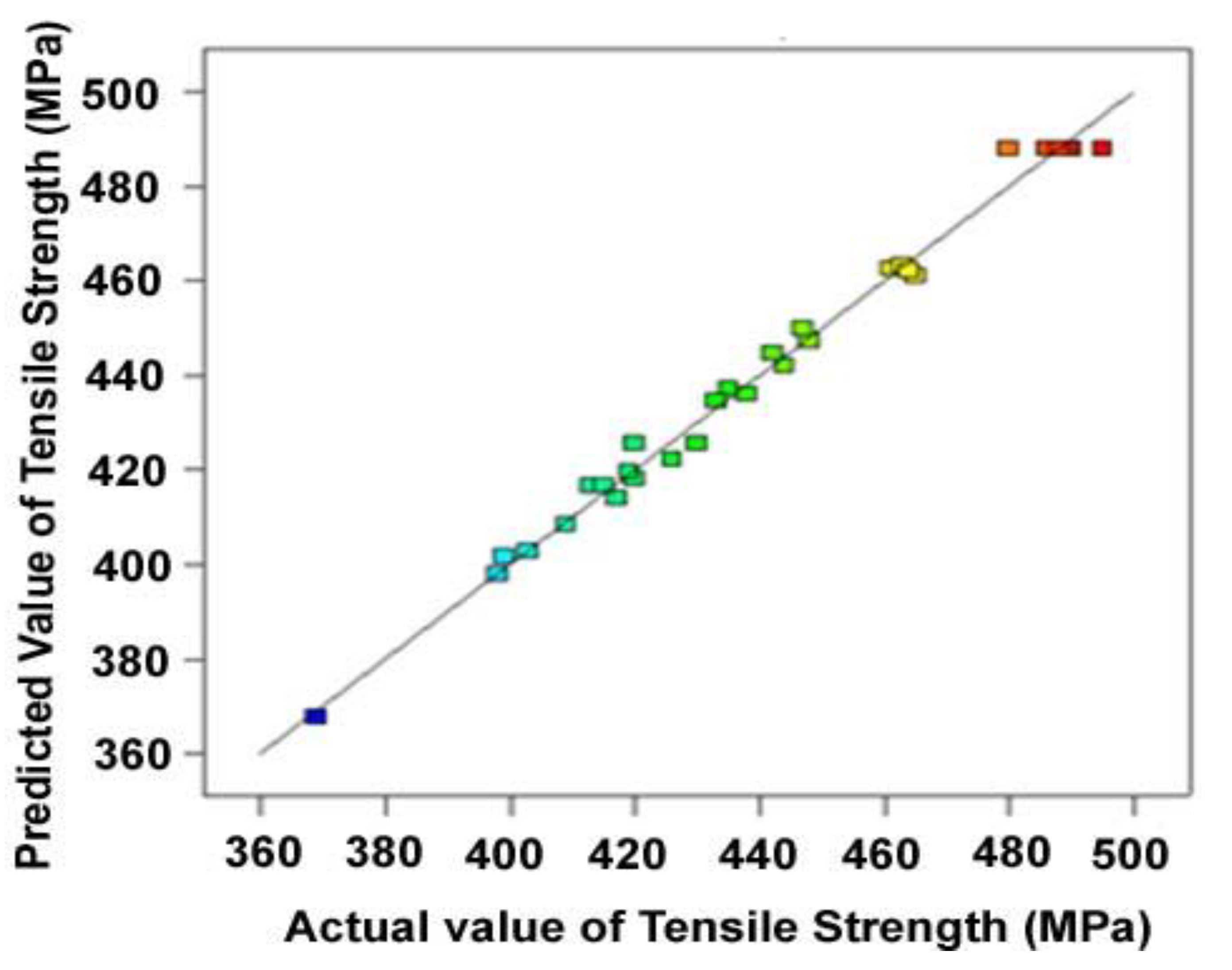
The analysis of variance (ANOVA) method was employed to determine whether the established empirical relationship was adequate. The intended level of confidence in this inquiry was set at 95%. The relationship may be deemed adequate if (a) the calculated value of the developed model’s F-ratio does not exceed the value of the standard tabulated “F”-ratio, and (b) the calculated value of the established relationship’s “R”-ratio exceeds the value of the standard tabulated “R”-ratio for the desired level of confidence. The model is determined to be suitable. The model is thought to be significant given the model F-value of 116.33. A model F-value this high might happen owing to noise only in 0.01% of cases. The lack of fit is assumed to be insignificant by the lack-of-fit F-value of 0.6431. Only 0.05% of the time may noise be the cause of such a large lack-of-fit F-value. As seen in Figure 2, each projected value closely corresponds to its experimental value.
The Fisher’s F-test, which has an extremely low probability value (Pmodel > F = 0:0001), shows that the regression model has a very profound importance. The determination coefficient was used to evaluate how well the model fit the data (R2). For the response, the coefficient of determination (R2) was calculated to be 0.9908. This suggests that the model does not only account for 0.925% of the overall changes but that 99.08% of the experimental data validate the compatibility with the data predicted by the model. The R2 value, which is always in the range from 0 and 1, represents how well the model fits the data. A decent statistical model should have an R2 value that is near to 1.0.The expression with the significant terms is rebuilt using the altered R2 value. In support of the model’s high significance, the adjusted determination coefficient’s value (Adj R2 = 0.9823) is similarly significant. The model could account for 95% of the variability in forecasting new findings, according to the Pred R2 of 0.9646. The Adj R2 of 0.9823 is in fair accord with this. The low coefficient of variation value of 0.979 suggests that there are not many differences between the experimental results and the predictions. The ratio of signal to noise is measured by adequate precision. A ratio of at least 4 is preferred. The ratio in this experiment is 39.47, which denotes a strong signal. To move around the design space, utilize this model.

5.3. Optimizing Friction Welding Parameters

The first stage in considering multiple reactions at once is to create an acceptable response surface model for each reaction. The next step is to identify a set of operational variables that, in some manner, maximizes all responses—or, at the very least, maintains them within predetermined bounds. By using Design-Expert software for the response surface analysis, anyone may easily characterize the response surface’s form and locate the optimal with a decent amount of precision by constructing response graphs and contour plots.
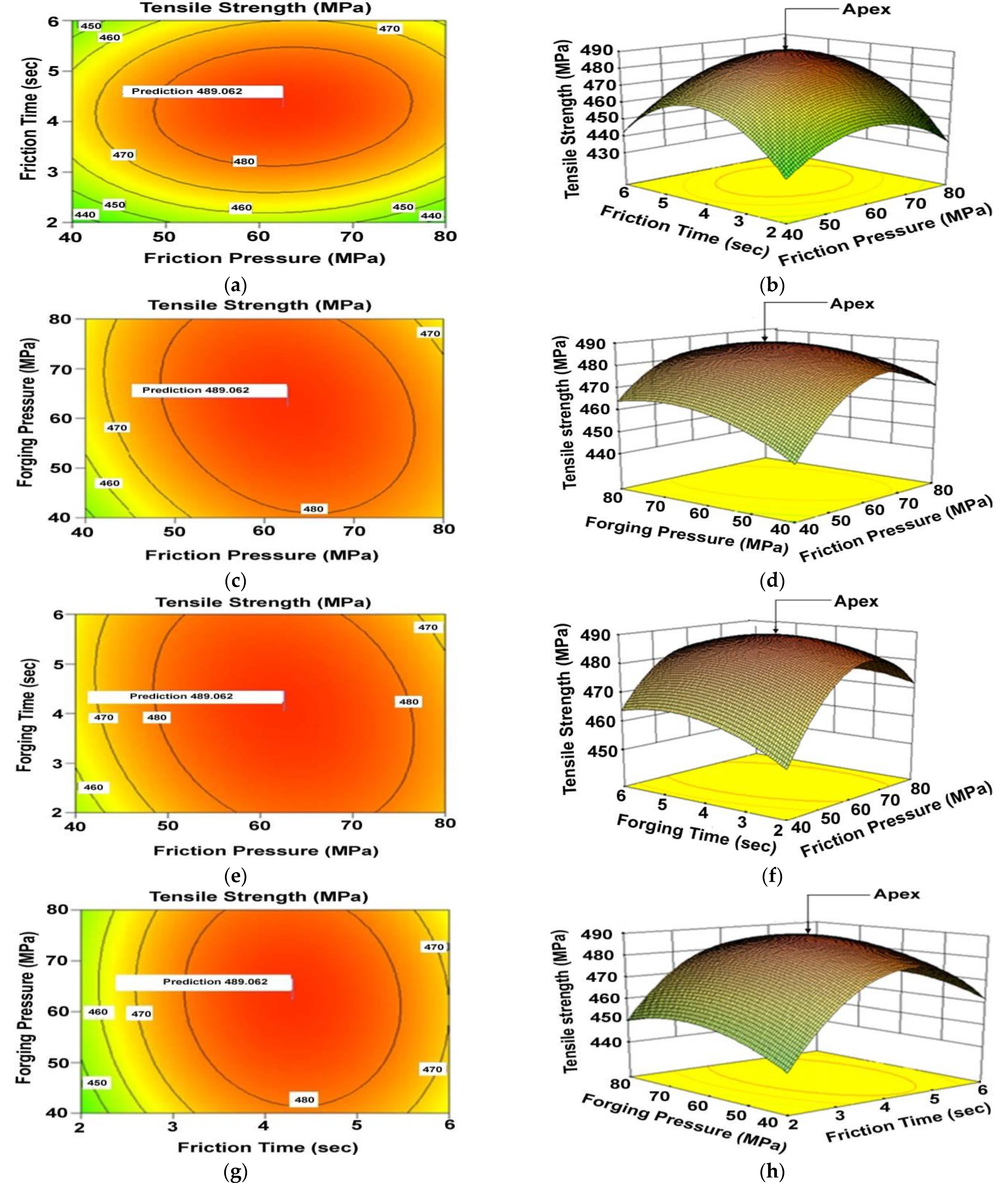
It may be deduced from Figure 3 that the response plot’s peak displays the highest possible UTS. If the degrees of freedom are the same for all the input variables, the contributions produced by the process conditions on the ultimate tensile strength can be rated [35,36] based on the specific F-ratio value that was observed in Table 6. The corresponding phrase is implied to be of greater significance by a larger F-ratio value and vice versa. According to the F-ratio values, the friction time has a greater impact on the joint’s ultimate tensile strength than the friction pressure, forging pressure, and forging time over the range under consideration in this study.
The characteristic circular mound shape in the contour plots suggests that the variables and the response may be independent of one another. To graphically depict the area of the ideal factor settings, a contour plot was created. Such a plot can be more complicated for second-order response surfaces than it is for first-order models, which can just be a simple set of parallel lines. Characterizing the response surface close to the stationary point once it has been located is typically necessary. To characterize a stationary point, one must determine whether it is a saddle point, a maximum response, or a minimum response. The easiest way to classify this is to look at a contour plot. Contour plots are essential for investigating the response surface. The optimum can be located quite precisely by characterizing the surface’s shape with the use of response surface analysis tools and contour plot production. A patterning of circular-shaped contours typically indicates the independence of the variable, but elliptical contours may indicate variable interactions. The response in the “Z”-axis, two parameters in the “X”- and “Y”-axes, and two variables in the middle level were used to generate the response surfaces for the suggested model. The response surfaces clearly show the appropriate reaction point. It is evident from Figure 3 that the TS rises as the friction pressure, forging pressure, and friction time increased until a certain point, at which point it falls.
The highest attainable UTS value is determined to be 489 MPa by examining the response surfaces and contour plots (Figure 3). The matching variables, friction pressure of 60 MPa, forging pressure of 60 MPa, and friction duration of 4 s, forging time of 4 s, produced this maximum value.

5.4. Analysis of Microstructure at an Optimized Condition

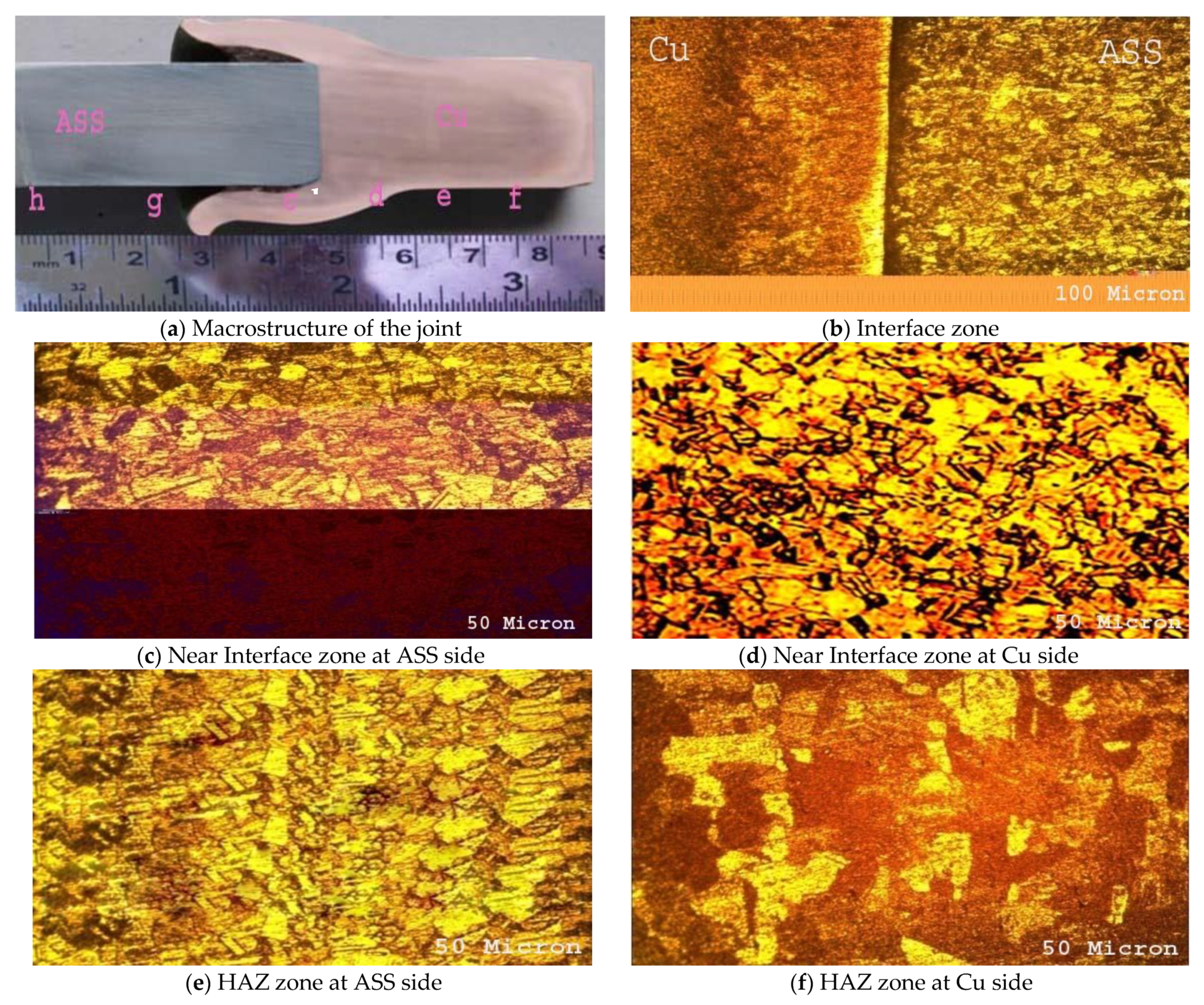
Figure 4 displays the cross-sectional optical micrographs of various regions of the welded joint made at the optimum friction-welding-process parameters. At two separate magnifications, Figure 4a,b display the weld cross-section of the dissimilar joints of an ASS-Cu joint. These micrographs obviously demonstrate the creation of an extremely thin interface area. Nevertheless, both base metals have significantly deformed regions closer to the joint line that are visible in Figure 4c,d. These regions are caused by thermomechanical action. The HAZ on the joint’s ASS side is seen in Figure 4e. The HAZ grains were recrystallized since rolling was used to create the primary austenitic phase of the base metal. However, due to the modest heat input of the welds, those grains did not appreciably increase in size. In some areas, the borders of the recrystallized austenite grains also produced the phase delta-ferrite. It has been demonstrated that ferrite grains that occur between austenite grain boundaries limit the grain growth and hot crack propagation in the HAZ. When compared to the parent metal, the grains in the HAZ on the copper side expand considerably. Near the contact, coarse granules are crucial as depicted in Figure 4f. Figure 4h shows the microstructure of the unaffected copper alloy. Figure 4g shows the microstructure of the unaffected SS. While there are no noticeable microstructure modifications on the ASS side, there are considerable microstructure variations on the Cu side close to the Cu-ASS weld interface. The full dynamic recrystallization zone and the partial dynamic recrystallization region are the names mentioned to the microstructures on the Cu side.
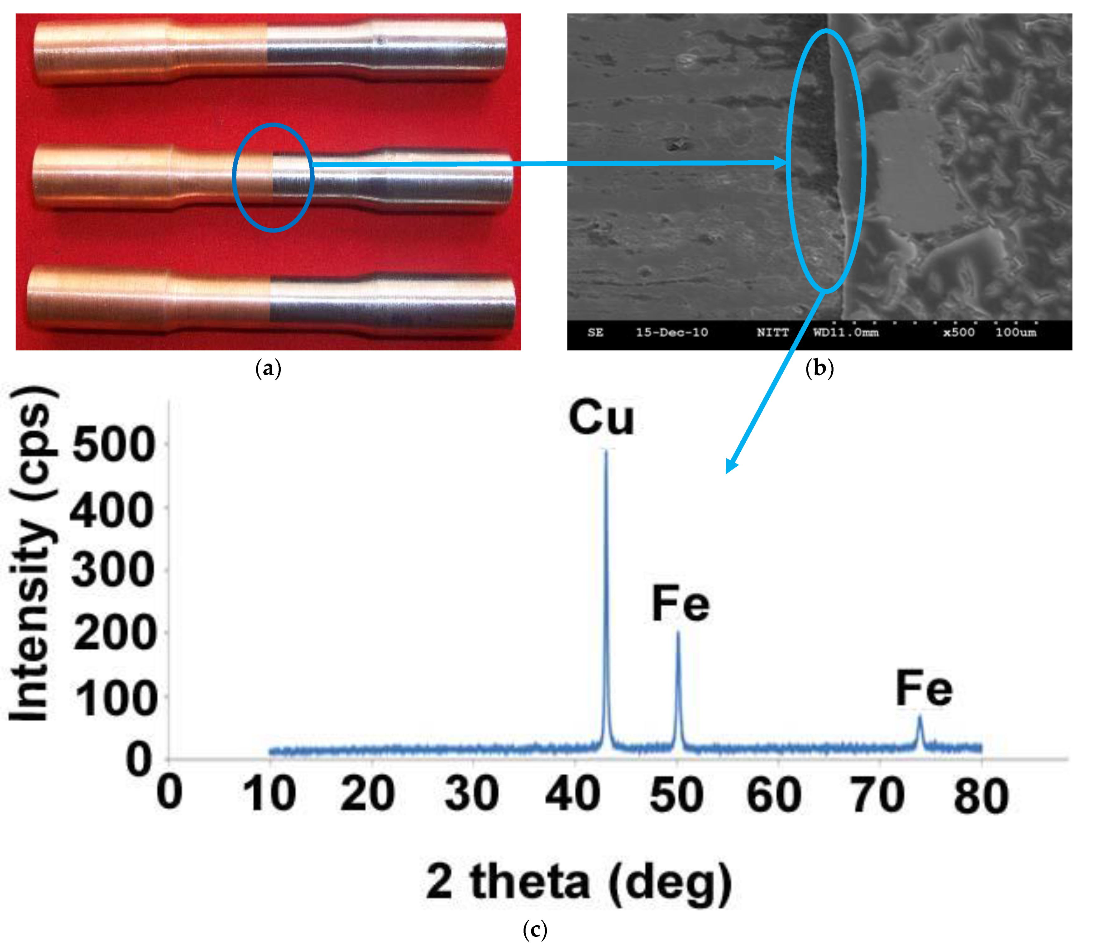
Scanning electron microscopy (SEM) was utilized to show how the weld contact zone between the ASS and Cu formed. Figure 5a illustrates the microstructure that the SEM was able to acquire. Figure 5a demonstrates that a very thin weld interface zone has formed. Subsequent analysis of the interface region using X-ray diffraction (XRD) has confirmed the existence of FeCu4 (Figure 5b). However, the formation of this thin layer is the nature of friction welding process and slightly deteriorates the tensile strength of the welded joints.

6. Conclusions

  • The tensile strength of friction-welded AISI 304 austenitic stainless steel and commercial copper dissimilar joints was predicted empirically using process variables. At a 95% confidence level, the established relationship can reliably be utilized to estimate the tensile strength of the friction-welded dissimilar joints of Cu-ASS.
  • The friction welding input variables were incorporated into response graphs and contour plots to create a list of the domains with the highest tensile strengths. The highest tensile strength of 489 MPa was discovered to be produced by friction welding under the following parameters: 60 MPa friction pressure, 60 MPa forging pressure, 4 s of friction time, and 4 s of forging time.
  • Friction time, friction pressure, forging pressure, and forging time were determined to have the greatest impact on the tensile strength of the joints of the four process variables studied.
  • Friction welding successfully joins the imperfect-free and leak-proof dissimilar materials of the Cu-ASS joints, making them acceptable for use in cryogenic heat exchanger applications.
  • While there are noticeable microstructure changes on the Cu side close to the Cu-ASS weld contact, there are no noticeable changes on the SS side. The wide dynamic recrystallization zone and the partial dynamic recrystallization zone are the names mentioned to the microstructures on the Cu side.

Author Contributions

Conceptualization, R.P.; Data curation, D.T.; Formal analysis, V.C.K.; Funding acquisition, O.S.A.; Investigation, M.A. (Mamdooh Alwetaishi); Methodology, A.N.A.; Project administration, C.S.R.; Resources, D.T. and R.P.; Software, R.P and V.C.K.; Supervision, D.T.; Validation, M.A. (Mohamed Abbas); Visualization, A.A.A. and R.P.; Writing—original draft, R.P.; Writing—review & editing, R.P., D.T. and C.S.R. All authors have read and agreed to the published version of the manuscript.

Funding

This research is supported by the Structures and Materials (S&M) Research Lab of Prince Sultan University and the authors acknowledge the support of Prince Sultan University for paying the article processing charges (APC) of this publication.

Institutional Review Board Statement

Not applicable.

Informed Consent Statement

Not applicable.

Data Availability Statement

Not applicable.

Acknowledgments

The authors extend their appreciation to the Deanship of Scientific Research at King Khalid University (KKU) for funding this work through the Research Group Program Under the Grant Number: RGP. 1/349/43. The authors would also like to acknowledge the support received by Taif University Researchers Supporting Project number (TURSP-2020/240), Taif University, Saudi Arabia, has provided support to the authors, which they would like to thank. S. Karthikeyan, of Annamalai University in Tamilnadu, India, has our deepest gratitude for his technical assistance during the statistical analysis section.

Conflicts of Interest

The authors declare no conflict of interest.

Nomenclature

FWFriction welding
TStensile strength MPa
AFriction pressure MPa
Bfriction time, Sec
Cforging pressure MPa
Dforging time, Sec
RSMResponse surface methodology
FZ-HAZFusion zone-Heat affected zone
UTSUltimate tensile strength

References

  1. Aritoshi, M.; Okita, K. Friction welding of dissimilar metals. Weld. Int. 2003, 17, 271–275. [Google Scholar] [CrossRef]
  2. Mehta, K.; Badheka, V.J. A Review on Dissimilar Friction Stir Welding of Copper to Aluminum: Process, Properties, and Variants. Mater. Manuf. Process. 2015, 31, 233–254. [Google Scholar] [CrossRef]
  3. Mehta, K.P. A review on friction-based joining of dissimilar aluminum–steel joints. J. Mater. Res. 2018, 34, 78–96. [Google Scholar] [CrossRef] [Green Version]
  4. Peng, H.; Chen, C.; Zhang, H.; Ran, X. Recent development of improved clinching process. Int. J. Adv. Manuf. Technol. 2020, 110, 3169–3199. [Google Scholar] [CrossRef]
  5. Gao, P.; Zhang, Y.; Mehta, K.P. Metallurgical and Mechanical Properties of Al–Cu Joint by Friction Stir Spot Welding and Modified Friction Stir Clinching. Met. Mater. Int. 2020, 27, 3085–3094. [Google Scholar] [CrossRef]
  6. Shanjeevi, C.; Kumar, S.S.; Sathiya, P. Multi-objective optimization of friction welding parameters in AISI 304L austenitic stainless steel and copper joints. Proc. Inst. Mech. Eng. Part B J. Eng. Manuf. 2014, 230, 449–457. [Google Scholar] [CrossRef]
  7. Sahin, M. Joining of stainless steel and copper materials with friction welding. Ind. Lubr. Tribol. 2009, 61, 319–324. [Google Scholar] [CrossRef]
  8. Li, Y.; Chen, C.; Yi, R.; Ouyang, Y. Review: Special brazing and soldering. J. Manuf. Process. 2020, 60, 608–635. [Google Scholar] [CrossRef]
  9. Han, J.; Paidar, M.; Vignesh, R.V.; Mehta, K.P.; Heidarzadeh, A.; Ojo, O.O. Effect of shoulder features during friction spot extrusion welding of 2024-T3 to 6061-T6 aluminium alloys. Arch. Civ. Mech. Eng. 2020, 20, 84. [Google Scholar] [CrossRef]
  10. Özdemir, N. Investigation of the mechanical properties of friction-welded joints between AISI 304L and AISI 4340 steel as a function rotational speed. Mater. Lett. 2005, 59, 2504–2509. [Google Scholar] [CrossRef]
  11. Yoon, H.-K.; Kong, Y.-S.; Kim, S.-J.; Kohyama, A. Mechanical properties of friction welds of RAFs (JLF-1) to SUS304 steels as measured by the acoustic emission technique. Fusion Eng. Des. 2006, 81, 945–950. [Google Scholar] [CrossRef]
  12. Fabritsiev, S.A.; Pokrovsky, A.S.; Nakamichi, M.; Kawamura, H. Irradiation resistance of DS copper/stainless steel joints fabricated by friction welding methods. J. Nucl. Mater. 1998, 258, 2030–2035. [Google Scholar] [CrossRef]
  13. Yilbaş, B.S.; Şahin, A.Z.; Kahraman, N.; Al-Garni, A.Z. Friction welding of St-Al and Al-Cu materials. J. Mater. Process. Technol. 1995, 49, 431–443. [Google Scholar] [CrossRef]
  14. Kalinin, G.; Gauster, W.; Matera, R.; Taqvassoli, A.F.; Rowcliffe, A.; Fabritsiev, S.; Kawamura, H. Structural materials for ITER in-vessel component design. J. Nucl. Mater 1996, 9, 233–237. [Google Scholar] [CrossRef]
  15. Fabritsiev, S.A.; Pokrovsky, A.S.; Zinkle, S.J.; Edwards, D.J. Low-temperature radiation embrittlement of copper alloys. J. Nucl. Mater 1996, 513, 233–237. [Google Scholar] [CrossRef] [Green Version]
  16. Fabritsiev, S.A.; Barabash, V.R.; Pokrovsky, A.S.; Chakin, V.P.; Grechanjuk, A.I.; Movchan Osokin, V.A. Effects of neutron irradiation on the properties of Cu-Mo dispersion strengthened alloy. Plasma Devices Oper. 2006, 4, 1–9. [Google Scholar] [CrossRef]
  17. Zinkle, S.J.; Fabritsiev, S.A. Copper Alloys for High Heat Flux Applications. Atomic and Plasma Materials Interaction Data for Fusion (Supplement to Nuclear Fusion). 1994; Volume 5, pp. 163–192. Available online: https://www.osti.gov/biblio/47760 (accessed on 27 November 2022).
  18. Mai, T.A.; Spowage, A.C. Characterisation of dissimilar joints in laser welding of steel–kovar, copper–steel and copper–aluminium. Mater. Sci. Eng. A 2004, 374, 224–233. [Google Scholar] [CrossRef]
  19. Fu, L.; Du, S.G. Effects of external electric field on microstructure and property of friction welded joint between copper and stainless steel. J. Mater. Sci. 2006, 41, 4137–4142. [Google Scholar] [CrossRef]
  20. Khanzadeh Gharahshiran, M.R.; Khoshakhlagh, A.; Khalaj, G.; Bakhtiari, H.; Banihashemi, A.R. Effect of post weld heat treatment on interface mi-crostructure and metallurgical properties of explosively welded bronze–carbon steel. J. Cent. South Univ. 2018, 25, 1849–1861. [Google Scholar] [CrossRef]
  21. Shanjeevi, C.; Kumar, S.S.; Sathiya, P. Evaluation of Mechanical and Metallurgical Properties of Dissimilar Materials by Friction Welding. Procedia Eng. 2013, 64, 1514–1523. [Google Scholar] [CrossRef]
  22. Jayabharath, K.; Ashfaq, M.; Venugopal, P.; Achar, D. Investigations on the continuous drive friction welding of sintered powder metallurgical (P/M) steel and wrought copper parts. Mater. Sci. Eng. A 2007, 454-455, 114–123. [Google Scholar] [CrossRef]
  23. Kimura, M.; Kusaka, M.; Kaizu, K.; Fuji, A. Effect of post-weld heat treatment on joint properties of friction welded joint between brass and low carbon steel. Sci. Technol. Weld. Join. 2010, 15, 590–596. [Google Scholar] [CrossRef]
  24. Jandaghi, M.R.; Saboori, A.; Khalaj, G.; Khanzadeh Ghareh Shiran, M. Mi-crostructural Evolutions and its Impact on the Corrosion Behaviour of Explosively Welded Al/Cu Bimetal. Metals 2020, 10, 634. [Google Scholar] [CrossRef]
  25. Ambroziak, A. Hydrogen damage in friction welded copper joints. Mater. Des. 2010, 31, 3869–3874. [Google Scholar] [CrossRef]
  26. Yeoh, C.K.; Jamaludin, S.B.; Ahmad, Z.A. The Effect of Varying Process Parameters on the Microhardness and Microstructure of Cu–Steel and Al–Al2O3 Friction Joints. J. Teknol. 2012, 41, 85–95. [Google Scholar] [CrossRef] [Green Version]
  27. Wang, Y.; Luo, J.; Wang, X.; Xu, X. Interfacial characterization of T3 copper/35CrMnSi steel dissimilar metal joints by inertia radial friction welding. Int. J. Adv. Manuf. Technol. 2013, 68, 1479–1490. [Google Scholar] [CrossRef]
  28. Luo, J.; Xiang, J.; Liu, D.; Li, F.; Xue, K. Radial friction welding interface between brass and high carbon steel. J. Mater. Process. Technol. 2012, 212, 385–392. [Google Scholar] [CrossRef]
  29. Shargh, S.F.; Saadat, A.; Najafi, A.; Gharehshiran, M.R.; Khalaj, G. Investigating the effect of post weld heat treatment on corrosion properties of explosive bonded interface of AA5083/AA1050/SS 321 tubes. Mater. Res. Express 2020, 7, 036529. [Google Scholar] [CrossRef]
  30. Sahin, A.Z.; Yibas, B.S.; Ahmed, M.; Nickel, J. Analysis of the friction welding process in relation to the welding of copper and steel bars. J. Mater. Process. Technol. 1998, 82, 127–136. [Google Scholar] [CrossRef]
  31. Pinto, R.; Afzal, A.; D’Souza, L.; Ansari, Z.; Mohammed Samee, A.D. Computational Fluid Dynamics in Turbomachinery: A Review of State of the Art. Arch. Comput. Methods Eng. 2017, 24, 467–479. [Google Scholar] [CrossRef]
  32. Afzal, A.; Ansari, Z.; Faizabadi, A.; Ramis, M. Parallelization Strategies for Computational Fluid Dynamics Software: State of the Art Review. Arch. Comput. Methods Eng. 2017, 24, 337–363. [Google Scholar] [CrossRef]
  33. Afzal, A.; Aabid, A.; Khan, A.; Afghan, S.; Rajak, U.; Nath, T.; Kumar, R. Response Surface Analysis, Clustering, and Random Forest Regression of Pressure in Suddenly Expanded High-Speed Aerodynamic Flows. Aerosp. Sci. Technol. 2020, 107, 106318. [Google Scholar] [CrossRef]
  34. Rajendran, P.R.; Duraisamy, T.; Seshadri, R.C.; Mohankumar, A.; Ranganathan, S.; Balachandran, G.; Murugan, K.; Renjith, L. Optimisation of HVOF Spray Process Parameters to Achieve Minimum Porosity and Maximum Hardness in WC-10Ni-5Cr Coatings. Coatings 2022, 12, 339. [Google Scholar] [CrossRef]
  35. Gunaraj, V.; Murugan, N. Application of Response Surface Methodology for Predicting Weld Bead Quality in Sub merged Arc Welding of Pipes. J. Mater. Process. Technol. 1999, 88, 266–275. [Google Scholar] [CrossRef]
  36. Tien, C.L.; Lin, S.W. Optimization of Process Parameters of Titanium Dioxide Films by Response Surface Methodology. Opt. Commun. 2006, 266, 574–581. [Google Scholar] [CrossRef]
Figure 1. Dimensions of the Unnotched Tensile Specimen.
Coatings 13 00261 g001
Figure 2. Correlation graph.
Coatings 13 00261 g002
Figure 3. Response graphs and contour plots for the effect of parameters on tensile strength (ah).
Coatings 13 00261 g003
Figure 4. Optical micrograph of various regions of dissimilar joint.
Coatings 13 00261 g004aCoatings 13 00261 g004b
Figure 5. (a,b) SEM micrograph of weld interface; (c) X-ray diffraction analysis at the weld interface.
Coatings 13 00261 g005
Table 1. Base metals chemical composition.
MaterialsCSiFeCuMnPNiCrAlOPbBS
Austenitic stainless Steel (ASS)0.080.75Bal-2.000.0451019----0.30
Copper (commercial
grade)
--0.007Bal----0.140.0920.0010.018<0.001
Table 2. Base metals’ mechanical characteristics.
MaterialsUltimate Tensile
Strength
(MPa)
Elongation (%)Notch Tensile Strength (MPa)Notch
Strength
Ratio
(NSR)
Impact
Toughness
@RT
(J)
Copper
(commercial grade)
344144761.3560
ASS460305751.2550
Table 3. Important factor and their levels.
NoFactorUnitNotationLevels
(−2)(−1)0(+1)(+2)
1Friction pressureMPaA4050607080
2Friction timeSecB23456
3Forging
pressure
MPaC4050607080
4Forging timeSecD23456
Table 4. Results of the experiment and the design matrix.
Expt.Coded ValuesOriginal ValuesTensile
NoStrength
ABCDA (MPa)B (s)C (MPa)D(s)(MPa)
1−1−1−1−1503503417
21−1−1−1703503435
3−1−1−1−1505503430
411−1−1705503461
5−1−11−1503703413
61−11−1703703420
7−111−1505703419
8111−1705703433
9−1−1−11503505403
101−1−11703505409
11−11−11505505415
1211−11705505438
13−1−111503705444
141−111703705420
15−1111505705448
161111705705442
17−2000404604399
182000804604426
190−200602604369
200200606604398
2100−20604404447
220020604804465
23000−2604602463
240002604606464
250000604604486
260000604604490
270000604604480
280000604604489
290000604604495
300000604604488
Table 5. Estimated regression coefficients.
FactorEstimated Coefficient
Intercept488
A-A5.125
B-B7.625
C-C2.791
D-D−0.291
AB3.437
AC−5.437
AD−4.437
BC−2.187
BD0.562
CD9.187
A2−19.031
B2−26.281
C2−8.156
D2−6.281
Table 6. ANOVA results.
SourceSum of SquaresdfMean SquareF-Valuep-Value Prob > F
Model30,283.88142163.135116.3323<0.0001 a
A-A630.3751630.37533.90125<0.0001
B-B1395.37511395.37575.04258<0.0001
C-C187.04171187.041710.059010.0063
D-D2.04166712.0416670.10980.7450
AB189.06251189.062510.167690.0061
AC473.06251473.062525.441070.0001
AD315.06251315.062516.94390.0009
BC76.5625176.56254.1174930.0606
BD5.062515.06250.2722590.6094
CD1350.56311350.56372.63258<0.0001
A^29934.31319934.313534.2624<0.0001
B^218,945.03118,945.031018.854<0.0001
C^21824.6711824.6798.12983<0.0001
D^21082.1711082.1758.19855<0.0001
Residual278.91671518.59444
Lack of Fit156.91671015.691670.6431010.7420 b
Pure Error122524.4
Cor Total30,562.829
S.D = 4.312128, mean = 440.2,C.V% = 0.979584, PRESS = 1079.52, R2 = 0.990874.a significant, b Not significant. Ad j R2 = 0.982356, Pred. R2 = 0.964679, Adeq precision = 39.47841.
Disclaimer/Publisher’s Note: The statements, opinions and data contained in all publications are solely those of the individual author(s) and contributor(s) and not of MDPI and/or the editor(s). MDPI and/or the editor(s) disclaim responsibility for any injury to people or property resulting from any ideas, methods, instructions or products referred to in the content.