
Properties and Performance of TiAlSiN and AlCrN Monolayer and Multilayer Coatings for Turning Ti-6Al-4V


1
School of Intelligent Manufacturing, Guangzhou Panyu Polytechnic, Guangzhou 511483, China
2
School of Electromechanical Engineering, Guangdong University of Technology, Guangzhou 510006, China
*
Authors to whom correspondence should be addressed.
Coatings 2023, 13(7), 1229; https://doi.org/10.3390/coatings13071229
Submission received: 13 June 2023
/
Revised: 3 July 2023
/
Accepted: 6 July 2023
/
Published: 10 July 2023
(This article belongs to the Special Issue Ceramic Materials and Coatings: From Materials to Applications)
Abstract
:The high chemical activity, low thermal conductivity, and high strength of titanium alloys lead to severe tool wear during cutting. The coating applied to the tool surface insulates the effect of heat and chemical reactions. TiAlSiN coating and AlCrN coating are two representative coatings with excellent properties in TiN-based and CrN-based applications, respectively. Three types of nanocoatings—TiAlSiN monolayer, AlCrN monolayer, and TiAlSiN/AlCrN multilayer—were prepared, and the microstructure, mechanical properties, oxidation resistance, diffusion properties with titanium alloy, and cutting performance of the coatings were investigated utilizing SEM, TEM, XRD, TGA, GD-OES, nanoindentation, and scratching instruments. The hardness, elastic modulus, and adhesion strength of TiAlSiN/AlCrN multilayer coatings are between TiAlSiN monolayer and AlCrN monolayer coatings, which meet the “law of mixtures”. Adhesion strength is the primary condition for cutting applications and should have a minimum threshold value. Ti and N elements are the most significant in the diffusion between coatings and titanium alloys. The nitride coating containing Cr aggravates the loss of N in contact with the titanium alloy. In addition, multilayer structural coatings can lead to more severe diffusion than monolayer coatings due to their inherent interlayer defects. Although diffusion between titanium alloys and coated tools is more severe than with other workpiece materials, the main factor affecting tool cutting life is still the H3/E*2 value determined by the hardness and modulus of elasticity together.
1. Introduction
There are problems of high stress, high cutting temperature, and severe tool wear during the cutting of titanium alloy. Compared to other workpiece materials, tools used to cut titanium alloys generally have significant adhesion and diffusion, which is related to the chemical activity of titanium alloys, in addition to microchipping, notch, and uniform flank wear. To deal with the high temperatures and chemical reactions with the tool substrate that occur during the cutting of titanium alloys, applying a coating on the tool surface to block the significant heat transfer and violent chemical reactions is still an effective method.
Transition metal nitride coatings are now the dominant strategy for cutting tool coatings, with many successful applications in the range of workpiece materials other than titanium alloys [1,2,3]. TiN and CrN are two types of binary nitride PVD coatings studied early and applied successfully. Then, the various properties of the coatings can be further improved by employing alloying methods. Al and Si are the most commonly used and successful alloying elements for coatings. Al plays a solid-solution-strengthening role in the above coatings, and the hardness of the coatings is increased by the influence of lattice distortion and preferred orientation caused by the addition of Al atoms. It is also found that the columnar crystal structure of TiN or CrN has become less pronounced, which can effectively prevent oxygen intrusion. In addition, the dense and chemically stable Al2O3 generated on the surface after Al is oxidized is also one of the reasons for the improved oxidation resistance of Al-containing coatings. AlTiN and AlCrN coatings have been successfully applied in cutting tools based on the above principles. Originated from the phase change of TiO2 at high temperature from dense α-TiO2 to loose r-TiO2, while Cr2O3 has no such change, AlCrN has better oxidation resistance than AlTiN. Vinay Varghese et al. [4] found that in milling MDN 250 maraging steel using AlCrN- and AlTiN-coated milling cutters, the AlCrN-coated tools had better wear resistance, attributed to the thin films of aluminum chromium oxide and chromium oxide on the surface. The flank wear of the AlCrN was only 0.26–0.35 mm in 25 min of cutting in dry, wet, and cryogenic environments, less than that of AlTiN.
Veprek and other researchers [5,6,7] attributed the superhard effect in coatings caused by Si addition to its unique nanocomposite structure. The general formula for this structure is expressed as nc-MeN/a-Si3N4, where Me = Ti, Cr, W, TiAl, CrAl. The mechanism of strengthening coating by nanocomposite structure has been studied. On the one hand, even at 1000 °C, the 2 phases of TiN and Si3N4 are strongly separated and not mutually soluble. The growth of TiN grains is inhibited by the surrounding Si3N4 phase, so that the TiN grains are refined up to about 10 nm, and in such small grains, the dislocations cannot move and proliferate, and the hardening effect is produced. On the other hand, the interface between Si3N4 and TiN is well bonded, so that the nanograins cannot slip along the grain boundary, which also has the effect of coating reinforcement. Due to its excellent hardness [8], oxidation resistance [9], and high-temperature stability [10], TiAlSiN coating is one of the most successful and widely used coatings among nanocomposite structural coatings. Harish C. Barshilia et al. [11] drilled holes in 304 stainless steel plates using a TiAlSiN nanocomposite-coated drill bit. The uncoated bit failed after drilling 50 holes, while the TiAlSiN-coated bit (Si = 5.5 at.%) drilled 714 holes before failure. S. Rodríguez-Barrero et al. [12] used a TiAlSiN nanocomposite-coated bit to drill 100 m on 42CrMo4 steel with less than 0.07 mm of flank wear and a longer working life than AlCrN, AlTiN, and AlCrSiN.
In the last decade, multilayering of coatings has become an inevitable trend to obtain the comprehensive performance of coatings. For example, adding an Ion-nitriding layer and an Intermetallic Ti-Al layer between the substrate and TiAlN coating can significantly improve the adhesion strength and corrosion resistance of the coating [13]. Using PFPE (perfluoropolyether) for the TiN surface layer to obtain a modified layer provides the tool surface with excellent wear resistance [14]. In addition, nanomultilayer coatings formed by alternating overlays of 2 different materials with thicknesses within 1–100 nm have been prepared. For example, Cr/CrN [15], CrN/ZrN [16], TiN/CrAlSiN [17], TiAlSiN/CrN [18], and AlTiCrN/TiSiN [19] have attracted attention for their excellent toughness, thermal stability, and corrosion resistance properties over monolayer coatings [20]. Baijun Xiao [21] found in an experiment on turning SKD11 that the AlCrN/AlTiSiN nanomultilayer-coated tool had a significantly longer tool life of ~800 m, which could be attributed to its higher hardness, adhesion strength, and oxidation resistance compared to the monolayer AlCrN or AlTiSiN coatings.
Previous studies on TiAlSiN or AlCrN or their multilayers have focused on oxidation resistance [21,22], microstructure [23], thermal stability [24], high-temperature friction [25], and wear when cutting non-titanium alloys [26,27,28]. However, there are few comparative studies on the performance and failure causes of all three coatings when cutting titanium alloys. In particular, the effect of diffusion between the titanium alloy and the coating on the cutting performance is an important issue.
In this work, TiAlSiN, a representative of TiN-based coatings, and AlCrN, a representative of CrN-based coatings, the former being a nanocomposite coating and the latter being a polycrystalline nanocoating, were prepared. Then, the TiAlSiN/AlCrN nanomultilayer coatings were prepared by alternately overlapping these two compositions. These three coatings’ physical phases, mechanical properties, and oxidation resistance were compared. In particular, the affinity of the coatings with titanium alloys was investigated in thermal diffusion experiments using a quantitative method. Finally, the coated tools’ cutting performance and wear were investigated by dry-cutting Ti-6Al-4V.
2. Materials and Methods
2.1. Coating Deposition
The coating technology in this paper is arc ion plating, and the coating equipment is a NH-10758 multifunctional PVD coater manufactured by Dongguan Nahu Crystal Materials Co. The coated substrate is mounted on a rotating frame in the middle of the furnace chamber and gets rotational motion in three dimensions, as shown in Figure 1. When making a monolayer coating, the target is mounted on the left or right side only; when making a multilayer coating, the targets of different compositions are mounted on the opposite sides. Since the modulation period of the multilayer coating is determined by the rotational speed of the rotating frame, the rotational speed of the rotating frame is set to 2 r/min for the 20 nm modulation period coating in this paper.
According to the deposition rates of different targets, the deposition time is calculated, and finally, the thickness of all types of coatings is guaranteed to be uniform at 3.5 ± 0.4 μm. The coated substrates are a cemented carbide WC-6 wt.% Co block of 18 × 18 × 5 mm for mechanical property testing and cross-sectional morphology observation, a Ti-6Al-4V block of 15 mm × 15 mm × 5 mm for the thermal diffusion test between the titanium alloy and coating, single-crystal alumina with a 51 mm outer diameter and 0.5 mm thickness for coating high-temperature oxidation, polycrystalline alumina of 23 mm × 10 mm × 0.5 mm for TGA, AISI 304 stainless steel of 60 mm × 10 mm × 0.8 mm for the residual stress test, and a carbide WC-6 wt.% Co 120408 standard turning insert for turning experiments. To improve the adhesion strength between the coating and substrate, all the substrates were polished by diamond grinding discs, and then the polished substrates were ultrasonically cleaned and loaded into the furnace chamber, which was evacuated to 5.0 × 10⁻³ Pa and heated to 500 °C. The total time for heating and holding was not less than 120 min. Next, argon was introduced and maintained at a pressure of 0.6 Pa; the substrate was glow cleaned at a bias voltage of 800 V for 9.5 min. The bias voltage was then reduced to 300 V, and the substrate was anodically etched for another 20 min to clean and activate the substrate surface. Then, nitrogen was introduced and applied in 3 steps according to 2–3–3 Pa. Corresponding to the 3-step nitrogen pressure, the bias voltage was applied according to 30–40–60 V, and the target current was applied according to 145–160–160 A. The purpose of the above steps is to form a gradient layer, reduce the residual stress, and enhance the adhesion between the film and the substrate. Finally, after the temperature was reduced to room temperature, the samples were taken out.
2.2. Coating Characterisation
The coatings’ surface and cross-sectional morphology and composition were tested using Nova NanoSEM 430 (FEI, Eindhoven, The Netherland). The physical phase analysis of the coatings was performed using a BRUKER D8 ADVANCE X-ray diffractometer (Bruker Corp, Billerica, MA, USA) with Cu Kα radiation (λ = 1.5406 Å). For grazing incidence XRD (GIXRD), the parameters were set to 2θ angle 25°~85°, step size 0.02°, dwell time 0.5 s per step, and incidence angle 1°. For conventional XRD, the dwell time per step was changed to 0.3 s. The microstructure of the multilayer coating was observed by transmission electron microscopy (FEI Talo F200S, ThermoFisher, Waltham, MA, USA), and the coating on the alumina substrate was thinned to 60 nm using the FIB technique before observation.
The hardness (H) and elastic modulus (E) of the coatings were obtained by nano-indentation tests using the TTX-NHT2 Nano-indenter (Anton Paar, Graz, Austria). The test parameters were set to a load of 10 mN, a loading rate of 15 mN/min, a maximum load maintenance time of 5 s, and an indentation depth of 120 nm. The indentation depth was limited to 10% of the film thickness to eliminate the effect of the substrate on the coating’s hardness. The adhesion strength between the coating and the carbide substrate was obtained by the scratching method using the Anton Paar RST3 (Anton Paar, Graz, Austria). The parameters were set to a scratch length of 3 mm, a load of 1–100 N, a loading rate of 200 N/min, and a diameter of 200 μm for the diamond tip. The coating residual stresses were tested using the FST-1000 film stress meter from Supro Instruments and then calculated based on the Stoney equation [29].
TGA testing of the coatings was performed using the thermogravimetric analyzer STA449F5 (NETZSCH Group, Bavarian, Germany) with a heating rate of 10 K/min and a continuous flow of dry air at 50 sccm throughout the experiment. The constant temperature oxidation experiments of the coatings were performed in the TSX1700 muffle furnace (Cinite, Beijing, China). The experimental temperatures were 800, 950, and 1050 °C, and the holding time was 3 h. The thermal diffusion between the coating and the titanium alloy was tested by GD-OES using a GD-Profiler 2 (HORIBA Scientific, Kyoto, Japan). The power was 30 W, and the air pressure was 650 Pa.
2.3. Cutting Experiment Planning
Turning is used to verify the cutting performance of the coating. The cutting test equipment includes a lathe (CAK3665nj, Shenyang NO.1 Machine Tool, Shenyang, China), an infrared thermal imaging camera (Testo 890-2 SET, Testo AG, Lenzkirch, Germany), a standard MSBNR2020K12 toolholder (Fengren Co., Ltd., Taizhou, China), and a standard SNMA120408 insert (ZGCC, Zigong, China), as shown in Figure 2. The CNC program for turning employs constant line speed cutting, which means that as the radius of the workpiece decreases, the spindle speed automatically increases, thus maintaining a constant cutting speed. Therefore, the tool assures an identical cutting speed, regardless of the workpiece diameter, and the cutting time can be used to measure the cutting life. The cutting temperature is measured by the infrared thermal imaging camera. Its parameters are as follows: maximum range 1200 °C, accuracy ±2 °C, emissivity setting range 0.01–1, spectral range 8–14 μm. The cutting parameters are as follows: Vc = 100 m/min, ap = 0.3 mm, f = 0.1 mm/r. When tool wear occurs, the amount of wear on the flank face is more straightforward to measure than that on the rake face, so the average wear length VB value on the flank face is often used to measure tool life. During machining, the VB of the tool is measured using a tool microscope at regular intervals.
3. Results and Discussion
3.1. Coating Composition, Physical Phase, and Microstructure
The cross-section and surface morphologies of TiAlSiN monolayer, AlCrN monolayer, and TiAlSiN/AlCrN multilayer coatings are shown in Figure 3.
The AlCrN coatings show noticeable columnar crystals, while TiAlSiN and TiAlSiN/AlCrN show the featureless morphology of Si-containing coatings. There are many white microparticles distributed on the surface of the coatings, showing a typical deposition of arc ion plating [30,31]. During the evaporation of the AlCr and TiAlSi target, the breakdown area of the arc spot produced by the cathodic arc on the target surface is tiny, and thus, the power density is large. Under the dual action of the pressure of internal expansion and the negative bias voltage at the substrate end, the metal droplets in the melt pool do not have enough time to evaporate before sputtering onto the substrate surface and then form the white microparticles. During the coating deposition, these microparticles were gradually covered by the subsequent deposited coatings or metal droplets, becoming a part of the coatings. This phenomenon is more apparent for the AlCrN coatings due to the lowest melting point of Al. These microparticles will increase the surface roughness if located on the outermost surface, form uneven defects inside the coating if buried deeply by the coating particles that come later, and form holes if dislodged by strong ion bombardment. EDS examined the chemical compositions of the three coatings, and the results are shown in Table 1. The ratio of each component of the coatings is close to the design target. However, the Si content is lower than the design target due to the lower deposition rate of Si than that of Al and Ti.
The results of XRD analysis of the coating using the GIXRD are shown in Figure 4. Both TiAlSiN and AlCrN coatings exhibit nitride peaks with (111), (200), (220), (311), and (222) crystal planes of cubic phase c-TiAlN and c-CrAlN each. The TiAlSiN coating has a strong TiN (200) plane preferred orientation, while the AlCrN coating exhibits a CrN (111) plane preferred orientation. The diffraction peaks of the TiAlSiN/AlCrN multilayer coating are located between the TiN and CrN standard peaks, which indicates that the multilayer coating exhibits a mixed structure of cubic phase c-TiAlCrN with a (200) plane of preferred orientation. The significant w-AlN phase was present in both TiAlSiN and TiAlSiN/AlCrN coatings, but not in AlCrN coatings, despite the high Al content of 70 at.% in AlCrN. This result also appeared in the study of other researchers [32]. This is because the solid solution of Al in CrN is greater than that in TiN; moreover, the Si addition further reduces the solid solution of Al in TiN, and the above combined causes lead to the appearance of a significant w-AlN phase in both TiAlSiN and TiAlSiN/AlCrN coatings.
The microstructure of TiAlSiN/AlCrN multilayer coatings was analyzed using HRTEM. As confirmed by HAADF-STEM in Figure 5, the TiAlSiN/AlCrN coating is an alternately stacked nanomultilayer structure with the layer interface perpendicular to the growth direction. The mapping scan of the elements confirms that the nanomultilayer structure consists of alternating AlCr-rich and TiSi-rich sublayers with a modulation period of about 20 nm, consistent with the designed modulation period.
Figure 6a clearly shows two different arrangement styles of lattice stripes, which, combined with the elemental scan results obtained in Figure 5, can be inferred to be TiAlSiN and AlCrN, respectively. Since the deposition rate of TiAlSiN is slightly lower than that of AlCrN, the TiAlSiN sublayer is slightly thinner, and the modulation ratio is slightly less than 1:1. The grain size can be estimated between 3 and 8 nm from the lattice stripe image of larger magnification in Figure 6b. The upper right illustration in Figure 6b shows the selected area electron diffraction pattern (SAED) in this region, which exhibits a polycrystalline diffraction ring feature. Compared with the XRD physical phase calibration results in Figure 4, it can be inferred that the polycrystalline diffraction ring is formed by each crystal plane of (111) fcc, (200) fcc, and (220) fcc of the face-centered cubic structure.
The inverse Fourier transform is performed on the two adjacent white box regions of c and d in Figure 6b individually, and the results are shown in Figure 6c and d, respectively, and the lattice stripes are calibrated. The spacings of the 2 crystal planes with different orientations in Figure 6c are 0.240 nm and 0.208 nm, respectively. The (111) and (200) crystal plane spacings of the standard CrN phase are 0.239 nm and 0.207 nm, respectively, from the PDF card, indicating that this region is where the AlCrN sublayer is located. The actual stripe spacing is slightly larger than the standard value because the Ti atoms are solidly solved in CrN, and the radius of Ti atoms is more significant than that of Cr atoms, resulting in lattice expansion.
Similarly, the spacings of the 2 crystal planes with different orientations in Figure 6d are 0.243 nm and 0.209 nm, respectively. The (111) and (200) crystal plane spacings of the standard TiN phase are 0.245 nm and 0.212 nm, respectively, from the PDF card, indicating that this region is where the TiAlSiN sublayer is located. The actual stripe spacing is slightly smaller than the standard value because the Cr atoms are solidly solved in TiN, resulting in lattice shrinkage. Ti and Cr are solving in each other’s nitride lattices because the two atoms are mixed in the same furnace cavity after being etched out of the TiAlSi and AlCr targets.
In addition, more indistinct zones appear in the lattice stripes of Figure 6d, indicating the presence of a large number of amorphous Si in the TiAlSiN sublayer region, which are wrapped around the Ti(Al)N nanocrystals. Referring to the XRD results in Figure 4 and the literature [5,6,7], it can be inferred that these amorphous Si are Si3N4.
3.2. Mechanical Properties
Figure 7 shows the nano-hardness and elastic modulus of TiAlSiN monolayer, AlCrN monolayer, and TiAlSiN/AlCrN multilayer coatings. The TiAlSiN coating achieves the highest hardness and lowest modulus of elasticity, while the TiAlSiN/AlCrN multilayer coating has these two values between the TiAlSiN monolayer and the AlCrN monolayer coating, following the “law of mixtures”. The resistance to plastic deformation and to wear of the coating can also be usually characterized by H3/E*2 with E* = E(1 − μ2), where μ is the Poisson’s ratio [33,34]. The larger the value of H3/E*2, the higher the resistance to plastic deformation and to wear of the coating. The TiAlSiN coating has the highest H3/E*2 value of 0.224 because it has the highest hardness and the lowest modulus of elasticity. Whether this superiority leads to outstanding cutting performance can only be verified in actual experiments.
The adhesion strength between the coating and the substrate is one of the key, and sometimes decisive, factors in assessing the performance of a coating. Obviously, a good adhesion strength can extend the service time. Figure 8 shows the large-load scratch test and the critical Lc2 and Lc3 values obtained for the three coatings. Lc2 is the load when cracks appear, and the coating sporadically flakes off. Usually, Lc2 is regarded as the critical load for coating failure and can be used to evaluate the adhesion strength of the coating; Lc3 is the load when the substrate is exposed. The adhesion strength of AlCrN coating is the highest; the Lc2 value of TiAlSiN coating is only 41 N. The adhesion strength of TiAlSiN/AlCrN coating is between the two. The difference between the Lc2 and Lc3 values of the multilayer coating is significant. The coating debris distributed on both sides of the scratch is powder-like, indicating that the multilayer coating is slowly peeling off as thin layers until the last sublayer leaves the substrate; in contrast, the difference between Lc2 and Lc3 of the two monolayer coatings is slight, indicating that the monolayer coating is rapidly peeling off as a whole after reaching the critical load Lc2, as evidenced by the large debris distributed on both sides of the scratch.
The worse adhesion strength of TiAlSiN coatings is related to the poor innate bonding of Si3N4 amorphous to the substrate crystal and the high residual compressive stresses after Si addition [33]. The film stress tester obtained residual stresses within all 3 coatings as compressive stresses—8.3 GPa for the TiAlSiN coating, 5.8 GPa for the AlCrN coating, and 3.8 GPa for the TiAlSiN/AlCrN multilayer—which was attributed to the multilayer structure effectively releasing the stresses within the whole coating.
3.3. High-Temperature Oxidation Resistance
The low thermal conductivity and high strength of titanium alloys cause the cutting process to be prone to high temperatures, so oxidation resistance is one of the essential properties that must be examined in coated tools. Figure 9 shows the TGA curves of TiAlSiN monolayer, AlCrN monolayer, and TiAlSiN/AlCrN multilayer coatings continuously heated from room temperature to 1450 °C in a synthetic air atmosphere. According to the rate of oxidative weight gain, the TGA curve can be divided into three stages: slight oxidation, rapid oxidation, and terminated oxidation. Before 965 °C, all 3 coatings showed no apparent oxidation weight gain and belonged to the slight oxidation stage. When the temperature reached 965 °C, the TiAlSiN coatings first showed noticeable oxidation weight gain, indicating a shift to the rapid oxidation stage. When the temperature increased to 1375 °C, the oxidation weight gain of the TiAlSiN coating no longer changed, indicating that the terminated oxidation stage was reached, and the whole TiAlSiN coating was completely oxidized. In contrast, the AlCrN coating did not terminate oxidation until the end of the experiment at 1450 °C, indicating that the AlCrN coating has superior high-temperature oxidation resistance than the TiAlSiN coating. It should be mentioned that the rapid oxidation starts, and the termination temperatures of TiAlSiN/AlCrN multilayer coatings are between the two monolayers.
Figure 10 shows the XRD patterns of the three coatings after constant oxidation at different temperatures for three hours. At 800 °C, the TiAlSiN and AlCrN coatings showed no oxide peaks, but the TiAlSiN/AlCrN multilayer coatings showed faint TiO2 and Al2O3 peaks at 35.8° and 64.5°, respectively. At 950 °C, oxide peaks started to appear for both TiAlSiN and AlCrN coatings. However, the peak intensity of the latter remained weak, which is consistent with the results of the TGA analysis in Figure 9. By the final 1050 °C, the intensity of the oxide peaks of the 2 Ti-containing coatings TiAlSiN and TiAlSiN/AlCrN continued to increase, while the increase in the oxide peak intensity of the AlCrN coating was extremely limited. It shows that the AlCrN coating has the most substantial oxidation resistance among the three coatings. It also shows that the multilayer structure of AlCrN and TiAlSiN did not hinder the inward diffusion of oxygen or the transport of metal atoms to the outer surface.
3.4. Thermal Diffusion between the Coating and the Titanium Alloy
Due to the high chemical activity of titanium alloys, chemical reactions between tools and titanium alloys are prevalent in cutting operations, which are significant factors affecting tool life. Therefore, it is essential to reveal the degree of chemical interaction between the coating and titanium alloy for the feasibility of cutting titanium alloy with coated tools. A total of 3 coatings were applied to the surface of the titanium alloy substrate and held at 950 °C for 3 h. The diffusion of elements at the interface between the coatings and the substrate was then analyzed using GD-OES. The deposited state samples of the coatings were also analyzed using GD-OES for comparison. As shown in Figure 11, both in the deposited state and after 950 °C treatment, the diffusion distances of both Ti and N significantly exceed those of the other elements, whose diffusion is confined within the mixed diffusion zone of Ti and N on both sides of the interface. Ti and N diffusion distances in the 3 coatings were similar in the deposited state, ranging from 1.08 nm to 1.68 nm. After the 950 °C treatment, the diffusion distance of Ti did not increase much, but that of N was much larger than that of Ti. This can be explained by the thermodynamic diffusion mechanism. Ti belongs to vacancy diffusion and N to interstitial diffusion, and the diffusion activation energy of Ti is much larger than that of N. Hence, the diffusion of Ti is more difficult than that of N.
It is also noted that within the Ti-6Al-4V, the variation of Ti and Al shows a seesaw effect, which means that when Al is enriched, the content of Ti decreases and vice versa. This is because the Al within Ti-6Al-4V originally formed a replacement solid solution relationship with Ti. When a large amount of N enters Ti-6Al-4V, the combination of Ti and N consumes a large amount of Ti, forcing Al out of its original position. However, there is a high concentration of Al from the coating on the left side of the interface, so Al can only migrate to the right side (inward), resulting in the “bulging” phenomenon on the curve. Therefore, it is also found that the bulging position on the Al curve corresponds to the depressed position of the Ti curve, which indicates that the Al has taken over the Ti lattice position by substitution at this position.
From the coating point of view, Ti diffusion is invasive diffusion, while N diffusion is lossy diffusion, and the loss of N is much more significant than the invasion of Ti. The loss of N within the coating means the disintegration of the coating crystal structure, thus reducing the service life of the coating. The diffusion distances of Ti and N elements in Figure 11 are shown in Figure 12. The effect of high-temperature treatment on N diffusion is more significant than that on Ti. Moreover, the loss of N in the AlCrN coating is greater than that of TiAlSiN. This is because the N atoms in the AlCrN coating tend to combine more with the Ti atoms in Ti-6Al-4V to generate TiN and so leave the coating. The generation of TiN can be demonstrated by XRD analysis of the sample’s surface after thermal diffusion of the AlCrN-Ti alloy. As shown in Figure 13, TiN peaks appear at 2θ = 36.6°, 42.5°, and 61.8°.
The following demonstrates the inevitability of TiN generation in terms of the Gibbs free energy of chemical reactions. The possible reactions with N involving the elements within the reaction system consisting of AlCrN coating and Ti-6Al-4V are as follows:
2Ti + N2(g) = 2TiN
2Cr + N2(g) = 2CrN
2Al + N2(g) = 2AlN
2V + N2(g) = 2VN
The Gibbs free energies of each of the above chemical reactions from the 0 to 1000 °C range are shown in Figure 14. Because Equation (1) has the lowest Gibbs free energy, Ti atoms are more easily bound to N atoms than Cr atoms. Driven by this reaction, the N atoms leave the coating and enter the titanium alloy until the reaction equilibrium is approached and the reaction rate becomes slower and slower.
Figure 12 also shows that the N loss of the TiAlSiN/AlCrN multilayer coating is greater than that of AlCrN, which is caused by a large number of defects between the layers of the multilayer coating, termed the “interlayer defect” problem, which can be explained by the model in Figure 15. Firstly, TiAlSiN and AlCrN have different lattice constants, although they belong to the same bcc-NaCl crystal structure. So, the interlayer lattice cannot form coherent epitaxial growth smoothly. Secondly, if two sublayers are to form a co-lattice epitaxial growth, one of the layers should be used as a template layer and the other layer as a modulation layer. The modulation layer abandons its own lattice structure and grows upward with the lattice type of the template layer, and its thickness is required to be thin. The experiments confirmed [35,36] that the modulation layer thickness should be controlled below 3 nm. The 2 sublayers of the multilayer coating in this work have a thickness of about 10 nm each, which far exceeds the thickness limited by the formation of coherent epitaxial growth of the modulated layer. Finally, as shown in Figure 15 and confirmed in Figure 4 and Figure 6, the TiAlSiN coating contains a large amount of amorphous Si3N4, which surrounds the TiN grains and adds difficulties to connecting TiN and CrN into a coherent structure [37].
The grain boundaries and crystallographic defects are more significant at the non-coherent layer interfaces than within the layers. Vacancies, dislocations, and bond deformations due to the irregular arrangement of atoms cause loose crystal structure and low stacking density at this location, which becomes a channel for the rapid diffusion of atoms (ions). Moreover, the loosening of the crystal structure also causes a decrease in the interatomic bonding force, which leads to a decrease in the diffusion activation energy and an increase in the degree of diffusion. It should also be added that multilayer coatings have finer grains than monolayer coatings, increasing grain boundaries.
Although interdiffusion between the titanium alloy and the coating does occur at high temperatures, the experimental results were obtained under high-temperature conditions lasting three hours. In the case of TiAlSiN/AlCrN, which has the highest N loss, the total diffusion distance for 3 hours is 10.36 − 1.19 = 9.17 μm, and the diffusion rate is about 0.051 μm/min. Assuming that the coating is applied for 30 min of cutting, the diffusion distance is only 1.528 μm. In the actual cutting process, it is not possible to maintain the tool temperature at 950 °C for a long time because of the necessary pause or cooling imposed. Therefore, the diffusion distance during cutting should be less than 1.528 μm.
3.5. Cutting Performance of Coated Tools
Turning Ti-6Al-4V experiments were implemented to study the wear and life of the coated tools. Figure 16 shows that the lives of TiAlSiN monolayer-, AlCrN monolayer-, and TiAlSiN/AlCrN multilayer-coated tools were 24.2 min, 25.9 min, and 30.4 min, respectively, under the wear criteria of 600 μm on the flank face.
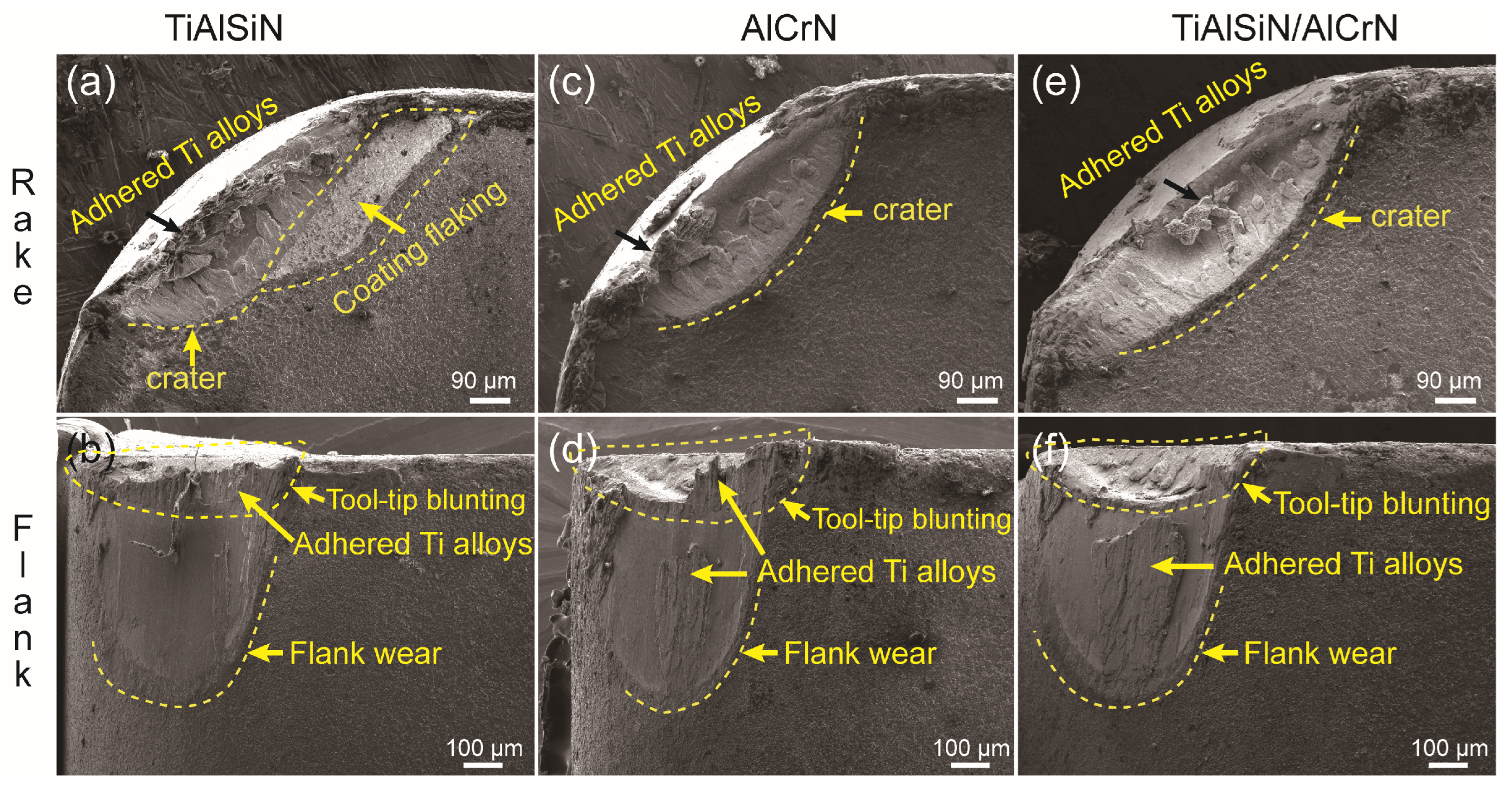
After cutting, SEM analysis was conducted on the rake and flank faces of the three tools, and the results are shown in Figure 17. The identical wear characteristics of the three coated tools are as follows. Crates are observed on the rake face, formed by the continuous flow of chips at the same spot, resulting in localized excessive wear. Uniform wear and tool-tip blunting can be observed on the flank face. Heavy Ti-6Al-4V adhesion was visible on both the rake and flank faces. The differences in the wear characteristics of the three coated tools are as follows. The TiAlSiN tool has a large coating flaking area on its rake face, which is directly related to its low adhesion strength, which is consistent with the test results of the adhesion strength of the TiAlSiN coating at room temperature revealed in Figure 8. It must be mentioned here that although the starting oxidation temperature of TiAlSiN coating is lower than that of the other two coatings at 965 °C, the highest cutting temperature measured in cutting experiments for the 3 coated tools is 750 °C, which can meet the need for oxidation resistance. Therefore, removing TiAlSiN coating should be mainly attributed to its lower adhesion strength, rather than oxidation resistance. The lower adhesion strength causes premature coating detachment before full service, seriously affecting the coated tool’s life.
The other two coated tools showed no coating flaking on the rake face, indicating that the adhesion strength had met the cutting requirements. In this case, the coating is gradually attrited, so as seen in Figure 16, the wear curves of both AlCrN- and TiAlSiN/AlCrN-coated tools are smoother than that of TiAlSiN-coated tools. It must be pointed out that in the static diffusion experiments in Figure 12, although more severe diffusion was also seen in TiAlSiN/AlCrN multilayers than in AlCrN, the cutting life of the former was not lower than that of the latter as a result, which indicates that diffusion with titanium alloys is not the most critical factor in determining the cutting life of the tool, but rather the hardness H and the modulus of elasticity E. More precisely, it should be the H3/E*2 value. The larger H3/E*2 values of TiAlSiN/AlCrN multilayer coatings provide higher plastic deformation and wear resistance.
4. Conclusions
Using the PVD cathodic arc evaporation technique, three types of nanocoatings—TiAlSiN monolayer, AlCrN monolayer, and TiAlSiN/AlCrN multilayer—were prepared, and the microstructure, mechanical properties, oxidation resistance, diffusion properties with titanium alloy, and cutting performance of the coatings were investigated.
- Among the many factors affecting coating performance, adhesion strength is the primary condition for cutting applications. When the adhesion strength is above a threshold value, the tool life starts to depend on other factors besides the adhesion strength. TiAlSiN coating has the lowest adhesion strength, leading to the lowest cutting life, despite its high H3/E*2 value and low titanium alloy affinity; AlCrN coating has the highest adhesion strength among the three coatings, but not the highest cutting life.
- All elements within the coating and the titanium alloy will inter-diffuse at high temperatures, but the Ti and N elements are the most significant. The intrusion of N in the coating into the titanium alloy side is much greater than the intrusion of Ti in the titanium alloy into the coating side. The nitride coating containing Cr aggravates the loss of N in contact with the titanium alloy. In addition, the multilayer structure of the coating does not prevent diffusion; on the contrary, the interlayer defects inherent in the multilayer structure can lead to more severe diffusion than in a monolayer coating.
- Compared to static diffusion experiments between the coating and the titanium alloy, the main factor affecting the life of the coated tool is not the two-party diffusion, but still the H3/E*2 value of the coating, given the shorter contact time and lower cutting temperature in the cutting application. That is why although the TiAlSiN/AlCrN multilayer coating has more severe diffusion than the AlCrN monolayer, the cutting life is instead higher owing to its higher H3/E*2 value.
Author Contributions
Conceptualization, J.L. and X.D.; methodology, Y.W.; validation, G.L. and J.H.; formal analysis, J.L.; investigation, J.H.; resources, X.D.; data curation, Y.W.; writing—original draft preparation, J.L.; writing—review and editing, X.D.; supervision, X.D.; project administration, G.L.; funding acquisition, X.D. All authors have read and agreed to the published version of the manuscript.
Funding
This research was funded by the Guangdong General University Featured Innovation Project (Grant No. 2022KTSCX294), Foshan Science and Technology Innovation Team Project (Grant No. FS0AAKJ919-4402-0023), Guangzhou Basic and Applied Basic Research Project (Grant No. 202201010393), and Jihua Laboratory Project (Grant No. X190061UZ190).
Institutional Review Board Statement
Not applicable.
Informed Consent Statement
Not applicable.
Data Availability Statement
The data presented in this study are available on reasonable request-from the authors (J.L. and X.D.).
Conflicts of Interest
The authors declare no conflict of interest.
References
- Patel, R.D.; Bhavsar, S.N.; Patel, A.K. Experimental investigation on cutting force during end milling of AISI D2 tool steel using AlCrN coated tool. Mater. Today Proc. 2023, 80, 1397–1402. [Google Scholar] [CrossRef]
- Sousa, V.F.; Silva, F.J.; Alexandre, R.; Fecheira, J.S.; Pinto, G.; Baptista, A. Experimental study on the wear evolution of different PVD coated tools under milling operations of LDX2101 duplex stainless steel. Adv. Manuf. 2022, 11, 158–179. [Google Scholar] [CrossRef]
- Azim, S.; Gangopadhyay, S.; Mahapatra, S.S.; Mittal, R.K. Performance evaluation of CrAlN and TiAlN coatings deposited by HiPIMS in micro drilling of a Ni-based superalloy. Surf. Coat. Technol. 2022, 449, 128980. [Google Scholar] [CrossRef]
- Varghese, V.; Akhil, K.; Ramesh, M.; Chakradhar, D. Investigation on the performance of AlCrN and AlTiN coated cemented carbide inserts during end milling of maraging steel under dry, wet and cryogenic environments. J. Manuf. Process. 2019, 43, 136–144. [Google Scholar] [CrossRef]
- Veprek, S.; Veprek-Heijman, M.G.J. Concept for the Design of Superhard Nanocomposites with High Thermal Stability: Their Preparation, Properties, and Industrial Applications. In Nanostructured Coatings; Cavaleiro, A., De Hosson, J.T.M., Eds.; Springer: New York, NY, USA, 2006; pp. 347–406. [Google Scholar]
- Veprek, S.; Jilek, M. Super and ultrahard nanacomposite coatings: Generic concept for their preparation, properties and industrial applications. Vacuum 2002, 67, 443–449. [Google Scholar] [CrossRef]
- Veprek, S.; Veprek-Heijman, M.J.G. Industrial applications of superhard nanocomposite coatings. Surf. Coat. Technol. 2008, 202, 5063–5073. [Google Scholar] [CrossRef]
- Das, C.R.; Rangwala, M.; Ghosh, A. Influence of substrate bias voltage on microstructure and mechanical characteristics of TiAlSiN coating deposited by High Power Impulse Magnetron Sputtering (HiPIMS). Surf. Coat. Technol. 2023, 458, 129351. [Google Scholar] [CrossRef]
- Zhang, K.; Xin, L.; Ma, T.; Chang, H.; Lu, Y.; Feng, C.; Zhu, S.; Wang, F. Investigation of the role of silicon in TiAlSiN coating deposited on TiAl alloys during long-term oxidation. Corros. Sci. 2022, 204, 110394. [Google Scholar] [CrossRef]
- Liu, Z.R.; Pei, F.; Chen, L.; Mayrhofer, P.H. Effect of Si-addition on structure and thermal stability of Ti-Al-N coatings. J. Alloys. Compd. 2022, 917, 165483. [Google Scholar] [CrossRef]
- Barshilia, H.C.; Ghosh, M.; Ramakrishna, R.; Rajam, K. Deposition and characterization of TiAlSiN nanocomposite coatings prepared by reactive pulsed direct current unbalanced magnetron sputtering. Appl. Surf. Sci. 2010, 256, 6420–6426. [Google Scholar] [CrossRef]
- Rodríguez-Barrero, S.; Fernández-Larrinoa, J.; Azkona, I.; López de Lacalle, L.; Polvorosa, R. Enhanced performance of nanostructured coatings for drilling by droplet elimination. Mater. Manuf. Process. 2016, 31, 593–602. [Google Scholar] [CrossRef]
- Vardanyan, E.; Ramazanov, K.; Nagimov, R.S.; Nazarov, A.Y. Properties of intermetallic TiAl based coatings deposited on ultrafine grained martensitic steel. Surf. Coat. Technol. 2020, 389, 125657. [Google Scholar] [CrossRef]
- Migranov, M.S.; Migranov, A.; Minigaleev, S.; Shehtman, S. Tribological properties of multilayer coatings for cutting tool. J. Frict. Wear. 2018, 39, 245–250. [Google Scholar] [CrossRef]
- Wieciński, P.; Smolik, J.; Garbacz, H.; Kurzydłowski, K. Failure and deformation mechanisms during indentation in nanostructured Cr/CrN multilayer coatings. Surf. Coat. Technol. 2014, 240, 23–31. [Google Scholar] [CrossRef]
- Vorontsov, A.; Filippov, A.; Shamarin, N.; Moskvichev, E.; Novitskaya, O.; Knyazhev, E.; Denisova, Y.; Leonov, A.; Denisov, V.; Tarasov, S. High-Temperature Oxidation of CrN/ZrN Multilayer Coatings. Metals 2022, 12, 1746. [Google Scholar] [CrossRef]
- Li, W.; Liu, P.; Zhu, X.; Pan, D.; Zhang, K.; Ma, F.; Liu, X. Effect of Si content on microstructural evolution and superhardness effect of TiN/CrAlSiN nanomultilayered films. J. Alloys Compd. 2015, 650, 592–597. [Google Scholar] [CrossRef]
- Liu, H.; Yang, F.-C.; Tsai, Y.-J.; Wang, X.; Li, W.; Chang, C.-L. Effect of modulation structure on the microstructural and mechanical properties of TiAlSiN/CrN thin films prepared by high power impulse magnetron sputtering. Surf. Coat. Technol. 2019, 358, 577–585. [Google Scholar] [CrossRef]
- Chang, Y.-Y.; Yang, Y.-J.; Weng, S.-Y. Effect of interlayer design on the mechanical properties of AlTiCrN and multilayered AlTiCrN/TiSiN hard coatings. Surf. Coat. Technol. 2020, 389, 125637. [Google Scholar] [CrossRef]
- Kameneva, A.; Kichigin, V. Corrosion, wear, and friction behavior of a number of multilayer two-, three-and multicomponent nitride coatings on different substrates, depending on the phase and elemental composition gradient. Appl. Surf. Sci. 2019, 489, 165–174. [Google Scholar] [CrossRef]
- Xiao, B.; Zhang, T.F.; Guo, Z.; Li, Z.; Fan, B.; Chen, G.; Xiong, Z.; Wang, Q. Mechanical, oxidation, and cutting properties of AlCrN/AlTiSiN nano-multilayer coatings. Surf. Coat. Technol. 2022, 433, 128094. [Google Scholar] [CrossRef]
- Fukumoto, N.; Ezura, H.; Suzuki, T. Synthesis and oxidation resistance of TiAlSiN and multilayer TiAlSiN/CrAlN coating. Surf. Coat. Technol. 2009, 204, 902–906. [Google Scholar] [CrossRef]
- Chen, W.; Lin, Y.; Zheng, J.; Zhang, S.; Liu, S.; Kwon, S. Preparation and characterization of CrAlN/TiAlSiN nano-multilayers by cathodic vacuum arc. Surf. Coat. Technol. 2015, 265, 205–211. [Google Scholar] [CrossRef]
- Hu, C.; Chen, L.; Lou, Y.; Zhao, N.; Yue, J. Influence of Si content on the microstructure, thermal stability and oxidation resistance of TiAlSiN/CrAlN multilayers. J. Alloys Compd. 2021, 855, 157441. [Google Scholar] [CrossRef]
- Xiao, B.; Liu, J.; Liu, F.; Zhong, X.; Xiao, X.; Zhang, T.F.; Wang, Q. Effects of microstructure evolution on the oxidation behavior and high-temperature tribological properties of AlCrN/TiAlSiN multilayer coatings. Ceram. Int. 2018, 44, 23150–23161. [Google Scholar] [CrossRef]
- Yue, Q.-B.; He, H.-B.; Li, H.-Y.; Zhang, J.; Li, Y.-M.; Ma, L. Research on friction characteristics of AlCrN and TiAlSiN coatings and properties of coated tools. Int. J. Precis. Eng. Manuf. 2019, 20, 1581–1589. [Google Scholar] [CrossRef]
- Rajguru, R.R.; Vasudevan, H. A study of micro hardness in the machining of Inconel 625 using TiAlSiN coated tools under dry cutting conditions. Adv. Mater. Process. Technol. 2022, 8, 1–11. [Google Scholar] [CrossRef]
- Silva, F.J.; Sousa, V.F.; Campilho, R.D.; Alexandre, R. Wear Behavior of Coated Tools When Milling S32101 Duplex Stainless Steel. Mater. Proc. 2022, 8, 45. [Google Scholar]
- Stoney, G.G. The tension of metallic films deposited by electrolysis. Proc. R. Soc. Lond. A 1909, 82, 172–175. [Google Scholar]
- Yousaf, M.; Pelenovich, V.; Yang, B.; Liu, C.; Fu, D. Effect of bilayer period on structural and mechanical properties of nanocomposite TiAlN/MoN multilayer films synthesized by cathodic arc ion-plating. Surf. Coat. Technol. 2015, 282, 94–102. [Google Scholar] [CrossRef]
- Mei, H.; Yan, K.; Wang, R.; Peng, W.; Huang, K.; Shi, J.; Zhang, D.; Gong, W.; Ren, F.; Wang, Q. Microstructure and mechanical properties of nanomultilayered AlTiN/Cu coatings prepared by a hybrid system of AIP and PDCMS. Ceram. Int. 2023, 49, 226–235. [Google Scholar] [CrossRef]
- Kimura, A.; Kawate, M.; Hasegawa, H.; Suzuki, T. Anisotropic lattice expansion and shrinkage of hexagonal TiAlN and CrAlN films. Surf. Coat. Technol. 2003, 169, 367–370. [Google Scholar] [CrossRef]
- Philippon, D.; Godinho, V.; Nagy, P.M.; Delplancke-Ogletree, M.P.; Fernández, A. Endurance of TiAlSiN coatings: Effect of Si and bias on wear and adhesion. Wear 2011, 270, 541–549. [Google Scholar] [CrossRef]
- Mayrhofer, P.H.; Mitterer, C.; Musil, J. Structure–property relationships in single- and dual-phase nanocrystalline hard coatings. Surf. Coat. Technol. 2003, 174–175, 725–731. [Google Scholar] [CrossRef]
- Li, W.; Liu, P.; Zhao, Y.; Zhang, K.; Ma, F.; Liu, X.; Chen, X.; He, D. SiNx thickness dependent morphology and mechanical properties of CrAlN/SiNx nanomultilayers. Thin Solid Films 2013, 534, 367–372. [Google Scholar] [CrossRef]
- KONG, M.; YUE, J.-L.; LI, G.-Y. Research development of hard ceramic nano-multilayer films. J. Inorg. Mater. 2010, 25, 113–119. [Google Scholar] [CrossRef]
- Li, W.; Liu, P.; Zhu, X.; Zhang, K.; Ma, F.; Liu, X.; Chen, X.; He, D. Si content dependent microstructure and mechanical properties of CrN/TiSiN nanomultilayered films. Mater. Sci. Eng. A 2014, 610, 28–32. [Google Scholar] [CrossRef]
Figure 1.
Layout of target and substrate for coating.
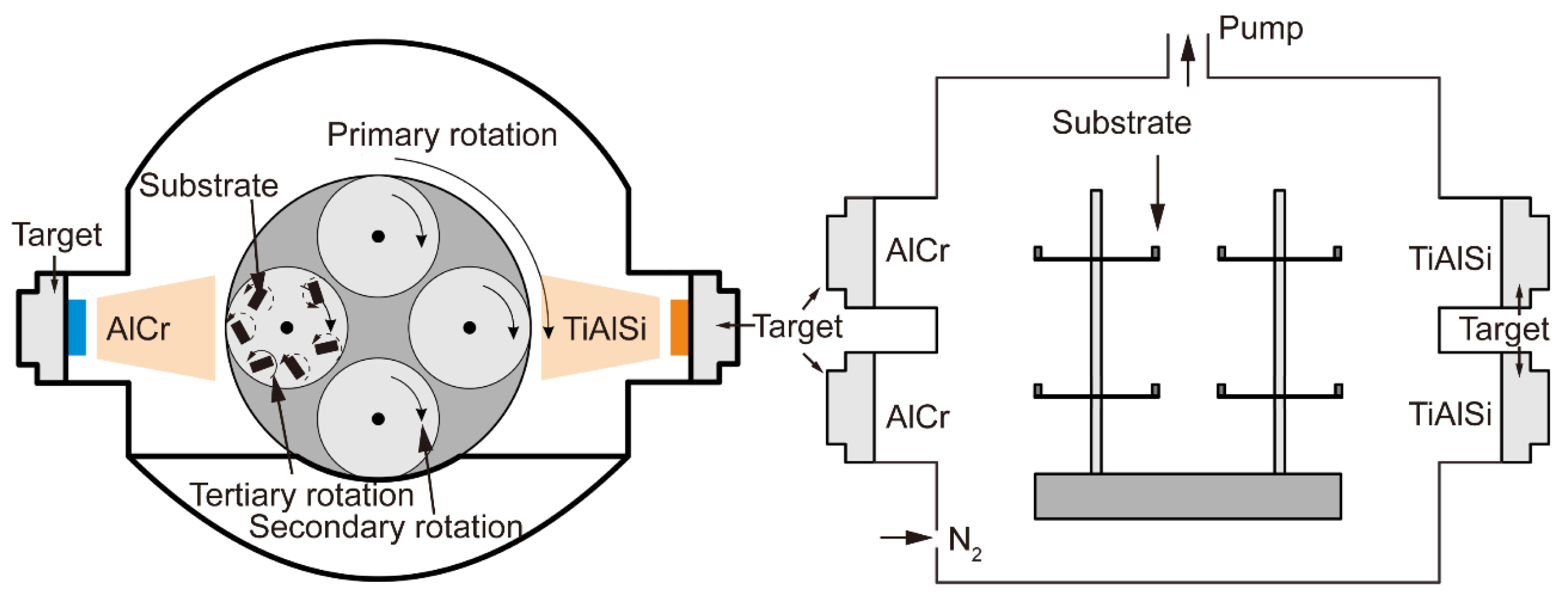
Figure 2.
The cutters and the cutting test equipment.
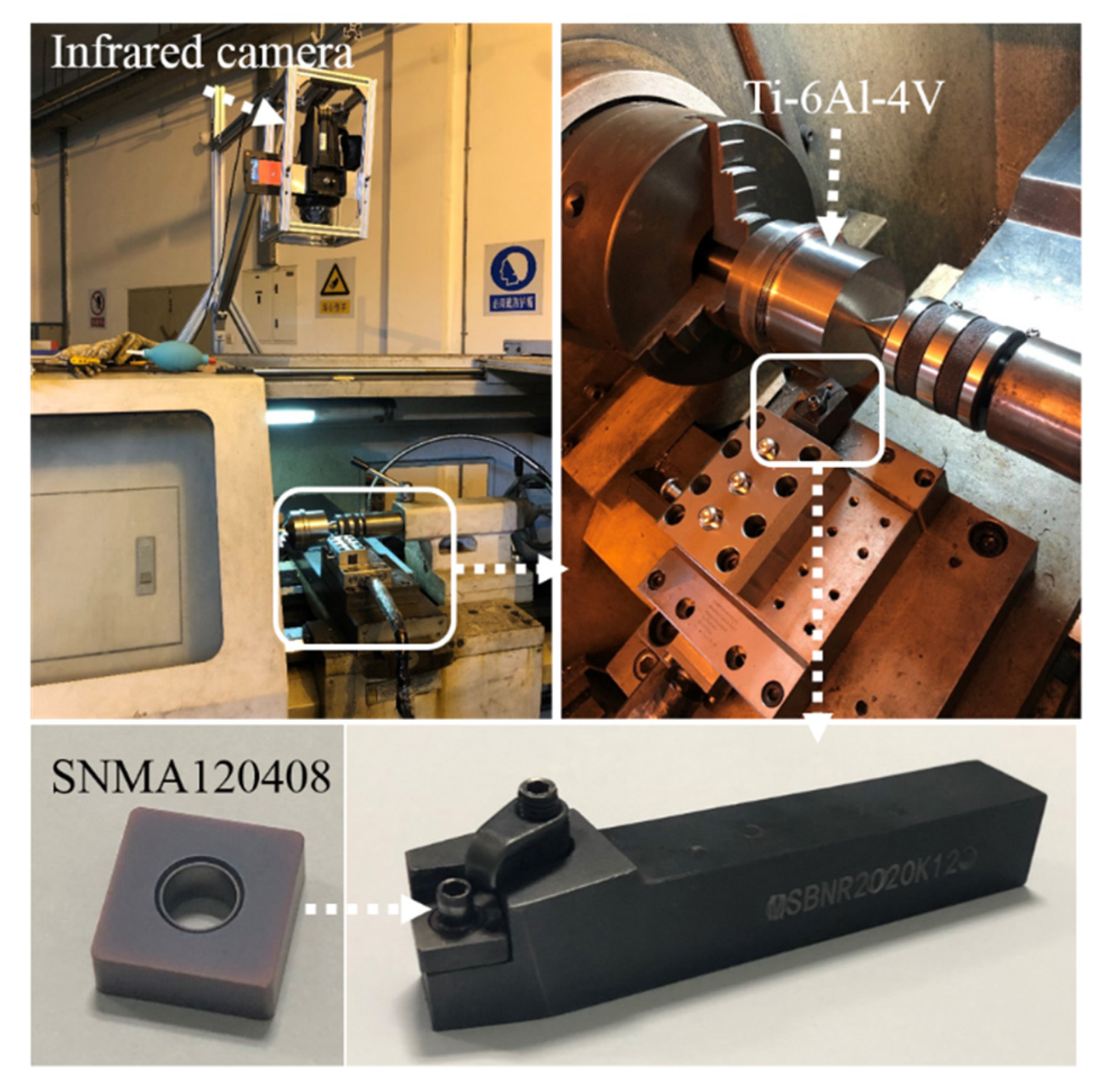
Figure 3.
Morphology of cross-section and top surface for three coatings: (a,b) TiAlSiN coating; (c,d) AlCrN coating; (e,f) TiAlSiN/AlCrN coating.
Figure 3.
Morphology of cross-section and top surface for three coatings: (a,b) TiAlSiN coating; (c,d) AlCrN coating; (e,f) TiAlSiN/AlCrN coating.

Figure 4.
XRD patterns of three coatings.
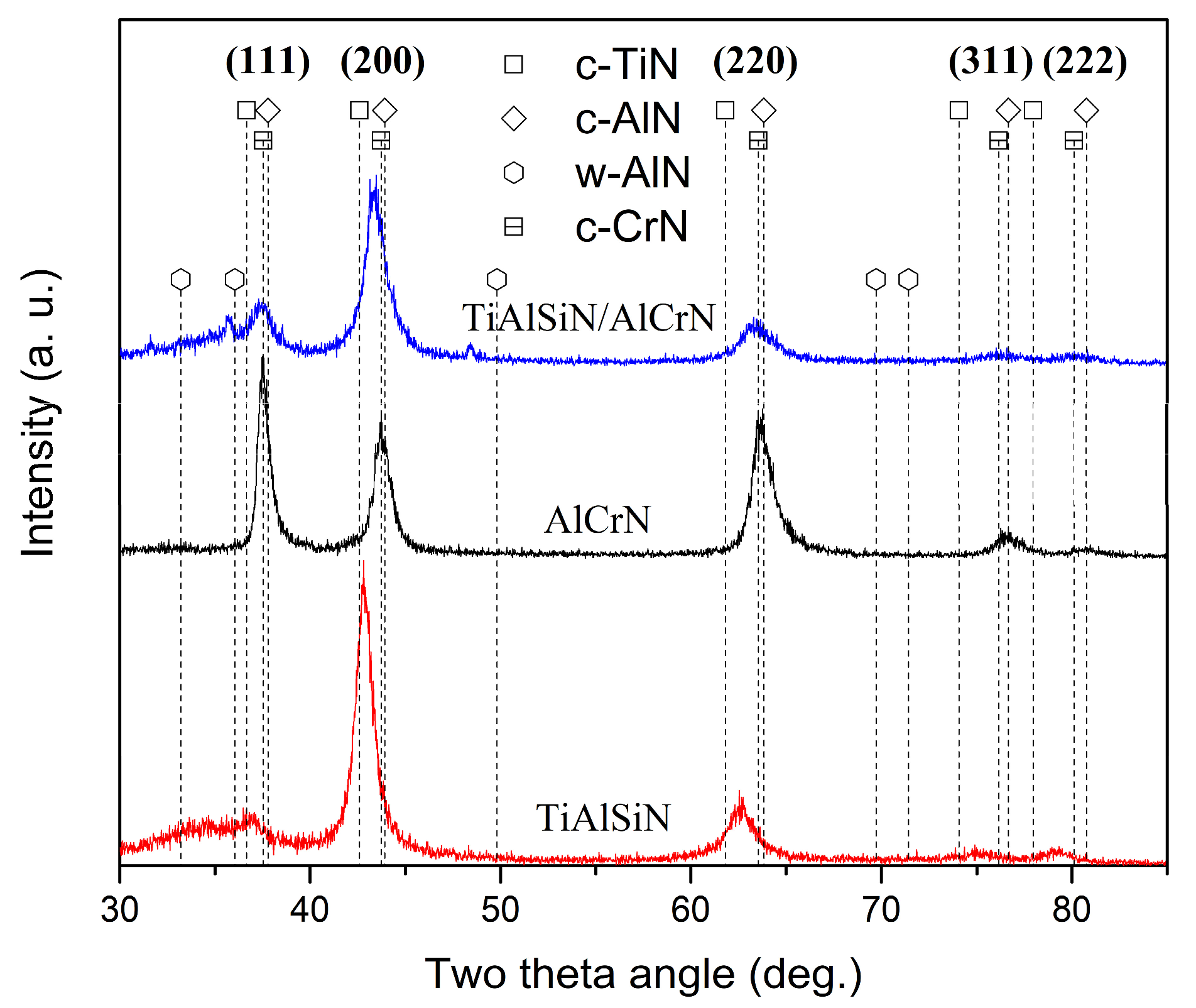
Figure 5.
HAADF-STEM topography of the cross-sectional area of the TiAlSiN/AlCrN coating and its element mapping.
Figure 5.
HAADF-STEM topography of the cross-sectional area of the TiAlSiN/AlCrN coating and its element mapping.

Figure 6.
High-resolution lattice fringe image and FFT of TiAlSiN/AlCrN coating: (a) Low-magnification image of HRTEM; (b) High-magnification image of HRTEM; (c) The IFFT in area c of Figure b; (d) The IFFT in area d of Figure b.
Figure 6.
High-resolution lattice fringe image and FFT of TiAlSiN/AlCrN coating: (a) Low-magnification image of HRTEM; (b) High-magnification image of HRTEM; (c) The IFFT in area c of Figure b; (d) The IFFT in area d of Figure b.
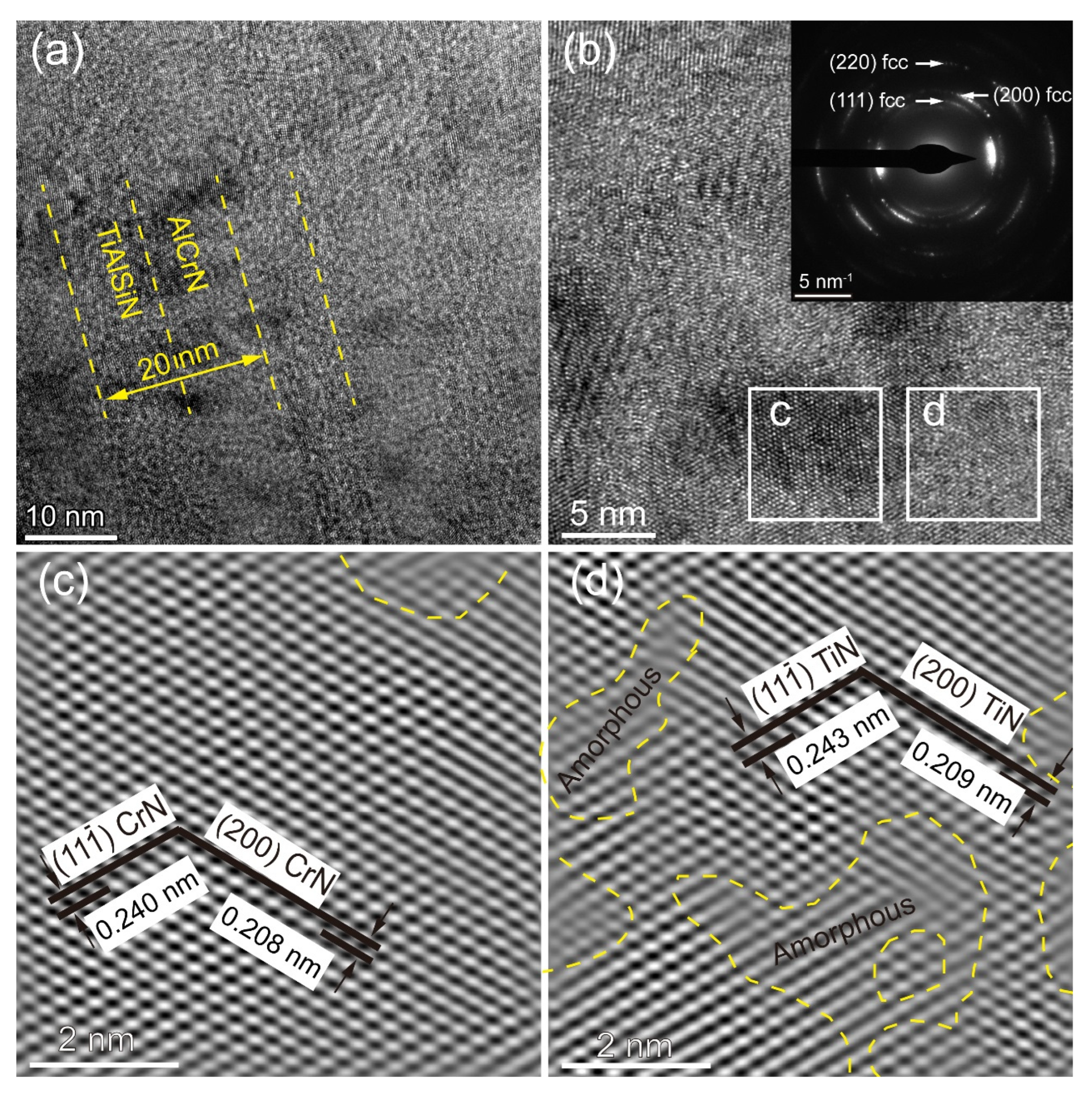
Figure 7.
Nano-hardness and elastic modulus of three coatings.
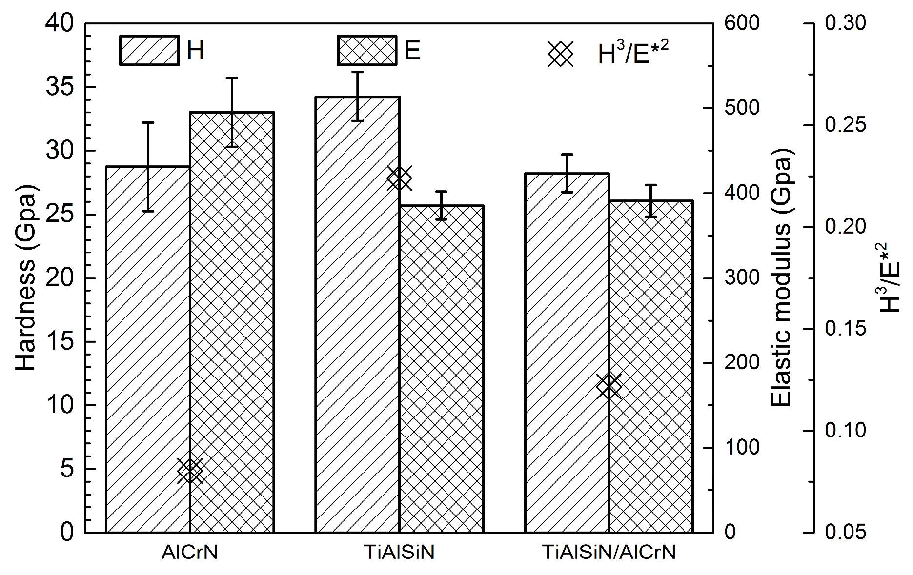
Figure 8.
The critical Lc2 value and corresponding optical graphs after the scratch test of three coatings.
Figure 8.
The critical Lc2 value and corresponding optical graphs after the scratch test of three coatings.

Figure 9.
TGA curves of three coatings in synthetic air atmosphere.
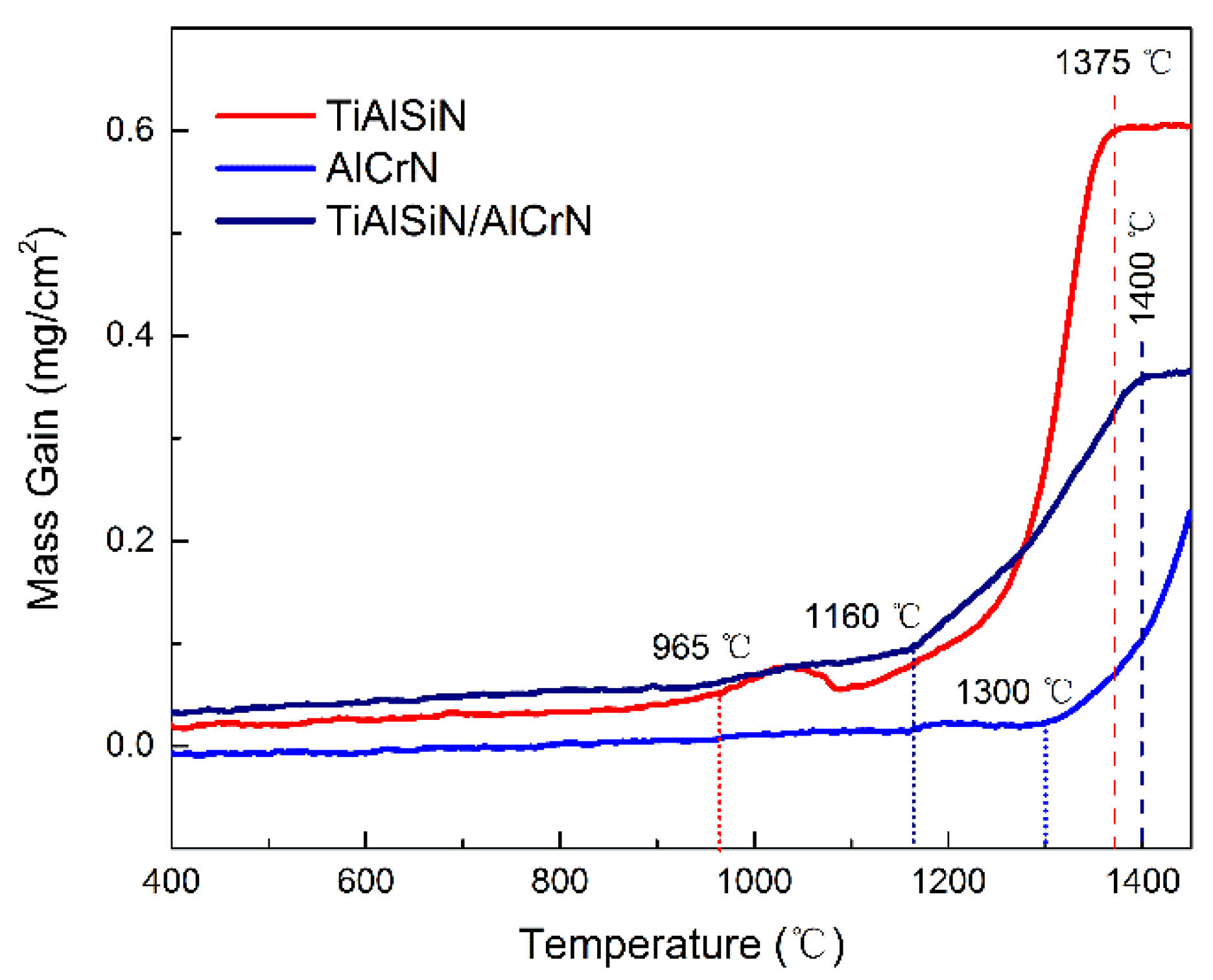
Figure 10.
XRD patterns of coatings after high-temperature oxidation test: (a) TiAlSiN coating; (b) AlCrN coating; (c) TiAlSiN/AlCrN coating.
Figure 10.
XRD patterns of coatings after high-temperature oxidation test: (a) TiAlSiN coating; (b) AlCrN coating; (c) TiAlSiN/AlCrN coating.
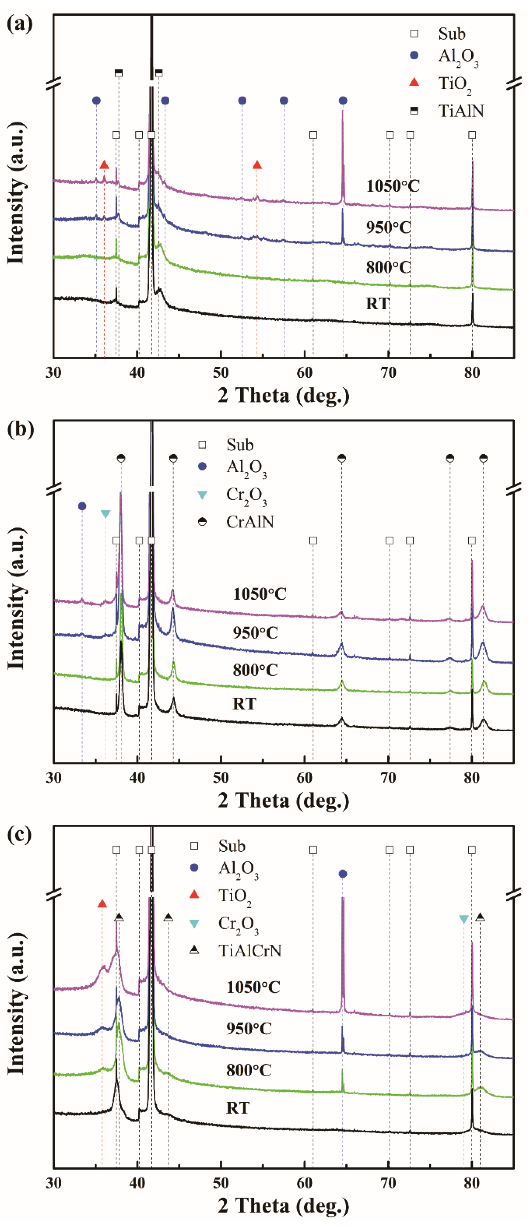
Figure 11.
GD-OES spectra of coatings on Ti-6Al-4V substrate before and after high-temperature treatment.
Figure 11.
GD-OES spectra of coatings on Ti-6Al-4V substrate before and after high-temperature treatment.
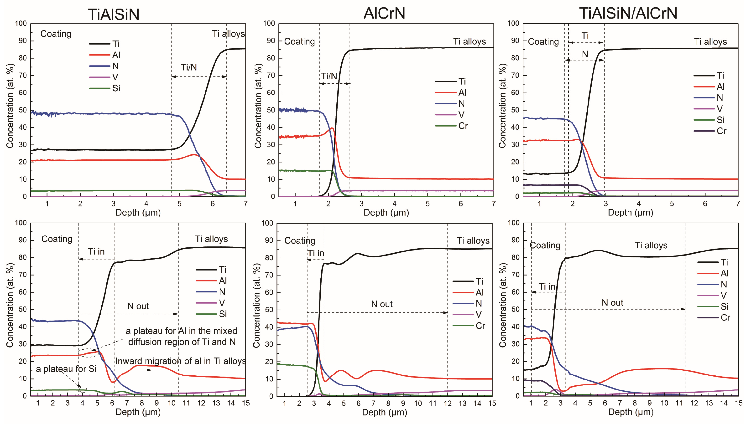
Figure 12.
The diffusion distance of Ti and N elements.

Figure 13.
XRD patterns of AlCrN coating on Ti-6Al-4V substrate after heat treatment at 950 °C for 3 h.
Figure 13.
XRD patterns of AlCrN coating on Ti-6Al-4V substrate after heat treatment at 950 °C for 3 h.
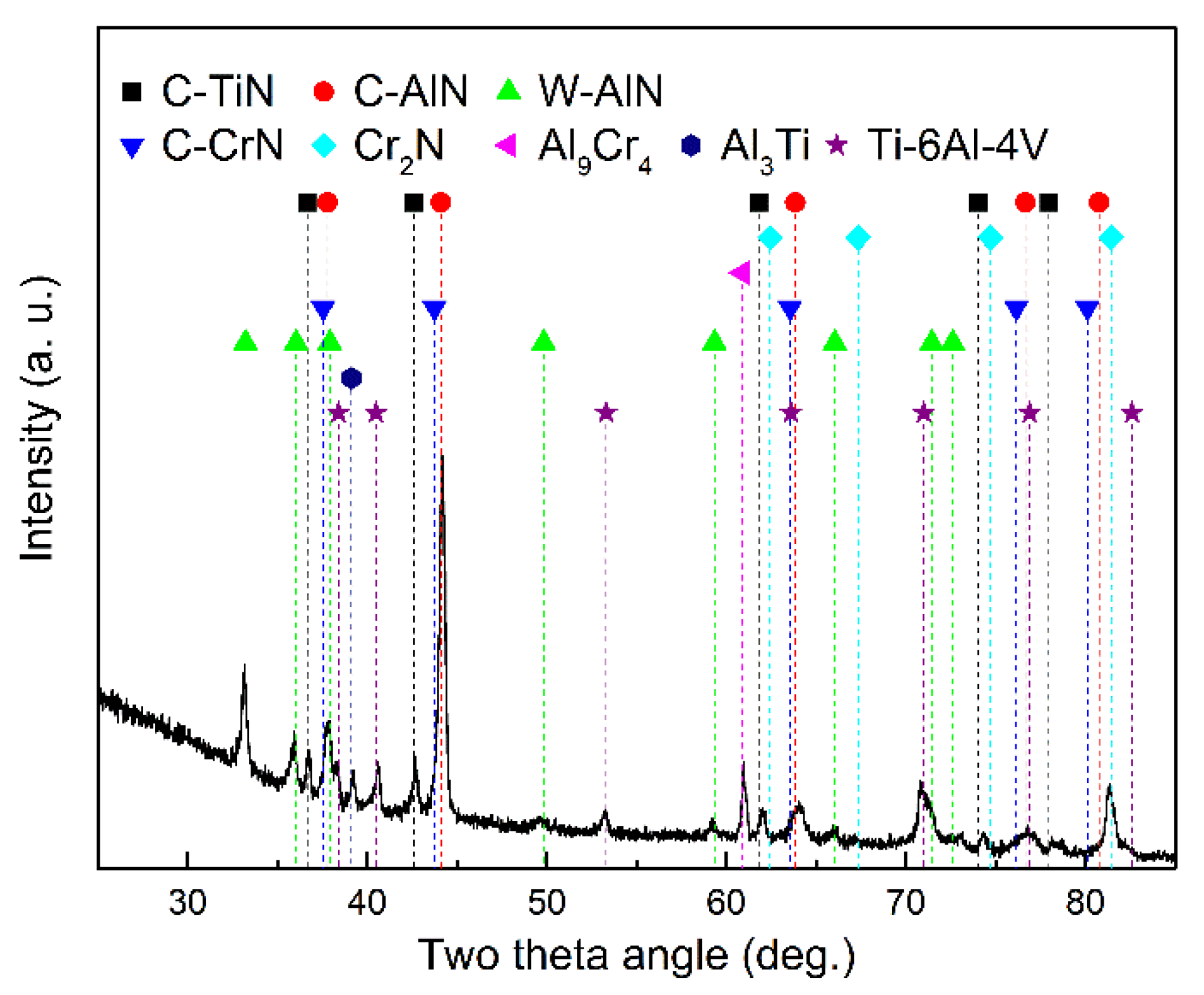
Figure 14.
Gibbs free energy of Ti, Al, V, and Cr reacting with N individually.
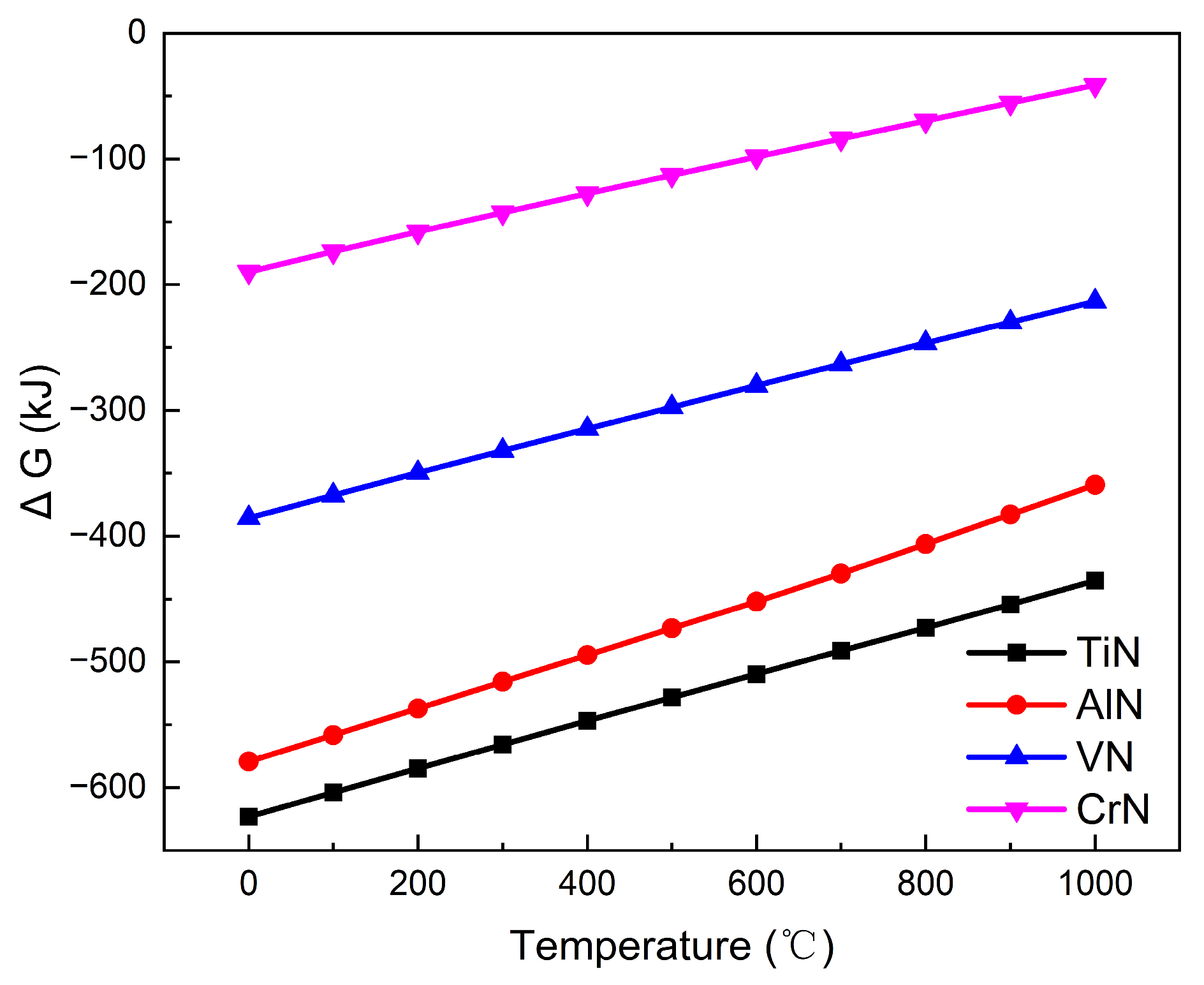
Figure 15.
Schematic diagram of TiAlSiN/AlCrN coating with nanomultilayers structures.
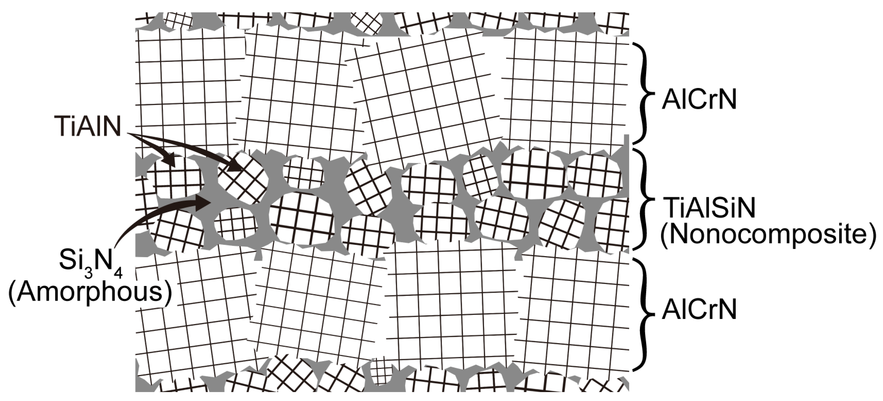
Figure 16.
Flank wear as the function of cutting time when cutting Ti-6Al-4V with three coated tools (cutting parameters: Vc = 100 m/min, ap = 0.3 mm, f = 0.1 mm/r).
Figure 16.
Flank wear as the function of cutting time when cutting Ti-6Al-4V with three coated tools (cutting parameters: Vc = 100 m/min, ap = 0.3 mm, f = 0.1 mm/r).

Figure 17.
Wear morphology of rake and flank of three coated tools at the end of cutting test. (a,b) TiAlSiN; (c,d) AlCrN; (e,f) TiAlSiN/AlCrN.
Figure 17.
Wear morphology of rake and flank of three coated tools at the end of cutting test. (a,b) TiAlSiN; (c,d) AlCrN; (e,f) TiAlSiN/AlCrN.

Table 1.
Coating thickness and composition measured by SEM and EDS.
| Target | Coating | Thickness (μm) | Chemical Composition (at.%) | ||||
|---|---|---|---|---|---|---|---|
| Al | Cr | Ti | Si | N | |||
| Ti0.45Al0.45Si0.10 | TiAlSiN | 3.69 | 20.22 | − | 22.66 | 3.89 | 53.23 |
| Al0.7Cr0.3 | AlCrN | 3.63 | 33.81 | 18.14 | − | − | 48.05 |
| Ti0.45Al0.45Si0.10 and Al0.7Cr0.3 | TiAlSiN/AlCrN | 3.87 | 27.95 | 8.01 | 10.97 | 2.23 | 50.85 |
Disclaimer/Publisher’s Note: The statements, opinions and data contained in all publications are solely those of the individual author(s) and contributor(s) and not of MDPI and/or the editor(s). MDPI and/or the editor(s) disclaim responsibility for any injury to people or property resulting from any ideas, methods, instructions or products referred to in the content. |
© 2023 by the authors. Licensee MDPI, Basel, Switzerland. This article is an open access article distributed under the terms and conditions of the Creative Commons Attribution (CC BY) license (https://creativecommons.org/licenses/by/4.0/).
Share and Cite
MDPI and ACS Style
Liu, J.; Wang, Y.; Liu, G.; Hua, J.; Deng, X. Properties and Performance of TiAlSiN and AlCrN Monolayer and Multilayer Coatings for Turning Ti-6Al-4V. Coatings 2023, 13, 1229. https://doi.org/10.3390/coatings13071229
AMA Style
Liu J, Wang Y, Liu G, Hua J, Deng X. Properties and Performance of TiAlSiN and AlCrN Monolayer and Multilayer Coatings for Turning Ti-6Al-4V. Coatings. 2023; 13(7):1229. https://doi.org/10.3390/coatings13071229
Chicago/Turabian StyleLiu, Jie, Yongchao Wang, Guiqian Liu, Junfang Hua, and Xin Deng. 2023. "Properties and Performance of TiAlSiN and AlCrN Monolayer and Multilayer Coatings for Turning Ti-6Al-4V" Coatings 13, no. 7: 1229. https://doi.org/10.3390/coatings13071229
Note that from the first issue of 2016, this journal uses article numbers instead of page numbers. See further details here.