
Design and Preparation of Bending-Resistant Flexible All-Solid Dye-Sensitized Solar Cells


1
Key Laboratory of Functional Materials and Devices for Informatics of Anhui Higher Education Institutes, Fuyang Normal University, Fuyang 236037, China
2
College of New Energy, Xi’an Shiyou University, Xi’an 710065, China
3
College of Intelligent Manufacturing, Shaanxi Institute of Technology, Xi’an 710300, China
*
Author to whom correspondence should be addressed.
Coatings 2024, 14(4), 504; https://doi.org/10.3390/coatings14040504
Submission received: 19 March 2024
/
Revised: 15 April 2024
/
Accepted: 16 April 2024
/
Published: 18 April 2024
(This article belongs to the Special Issue Advanced Polymer and Thin Film for Sustainable Energy Harvesting)
Abstract
:All-solid-state flexible dye-sensitized solar cells will not only expand the application scenarios of solar cells but also significantly extend the lifetime of solar cells. However, improving their bending-resistant ability is still a great challenge. In this study, a bending-resistant flexible all-solid dye-sensitized solar cell was designed and prepared. Firstly, for the preparation of TiO2 photoanode, the traditional nano-sized film has been replaced by dual-porous film with both nano and submicron pores, which can not only benefit the filling of the electrolyte but also supply the space for stress release. Secondly, for the filling of the Poly(vinylidene fluoride)/Poly(ethylene oxide)-based electrolyte, the solvent is removed by a vacuum method, and the electrolyte fibers forming in the submicron pores also show the potential for stress release. Lastly, combined with the advantages of the dual-porous TiO2 film and the fast evaporation of the polymer electrolyte, the conversion efficiency of the solar cells remains constant after the 20,000 bending times. The study supplies a demonstration for the development of all-solid-state flexible dye-sensitized solar cells.
1. Introduction
Dye-sensitized solar cells (DSCs) offer a technically and economically alternative concept to current p-n junction photovoltaic devices [1,2,3,4]. Different from the semiconductor in p-n junction cells, which performs both light absorption and carrier transport, the light is absorbed by the sensitizer on the surface of the wide band gap semiconductor in DSC, and the charge is separated at the interface between the sensitizer and the semiconductor, and then the carrier flows to the external circuit through the conduction band of the semiconductor. This innovative structure enables the independent development of photosensitizers and semiconductor materials [5] and even provides a prototype basis for quantum dot solar cells and perovskite solar cells [6,7].
The flexibility of DSCs further reduces the manufacturing cost and shows the advantages of bend resistance and suitability for rollable production. Several stable methods have been proposed for the low-temperature preparation of the TiO2 semiconductor mesoporous layers, such as low-temperature spin coating, low-temperature hydrothermal method, film transfer method, mechanical film pressing method, and vacuum cold spraying method [8,9], and some bending-resistant data of the TiO2 films have also been reported. Miyasaka et al. [10] prepared the TiO2 film through electrophoretic deposition, and the curvature of the TiO2 film was 0.2 mm−1. Murakami et al. [11] prepared the TiO2 film through chemical vapor deposition, and the bending radius of the TiO2 film was 5 mm. Kijitori et al. [12] and Chen et al. [13] prepared the TiO2 film using a low-temperature sintering method and mechanical film compression method separately, and both of the TiO2 films showed a good bending-resistant ability. However, the above original research only described the bending-resistant ability of TiO2 thin films, and the bending-resistant ability of the whole solar cells was not involved. The flexible DSC as a stacking system is composed of several functional layers, and when it is under an action of bending behavior, in addition to the neutral layer, most of the layers will produce bending stress due to the bending strain. According to the conventional conclusions of engineering mechanics, the different areas within each functional layer along the stress-loading direction will show different strain states, and every strain state may have a serious effect on the performance of the solar cells. Then, the bending behavior of the whole cell becomes increasingly important because it is highly realistic. Dai et al. [14] prepared the TiO2 film by cold isostatic pressing method, and after the TiO2 film was assembled into solar cells, the TiO2 film did not crack after 500 bending times. He et al. [15,16] established a standard to trace the bending-resistant ability of the solar cells, including bending modes, bending radius, and bending times, focusing on establishing the relationship between the structural change and performance evolution of the solar cells under various bending actions. Their research group pointed out that there was a critical bending radius, and when the bending radius was larger than the critical bending radius, the photovoltaic performance of the solar cells improved; otherwise, when the bending radius was smaller than the critical bending radius, the photovoltaic performance of the solar cells decreased with an increase in bending times due to the cracking and spalling of TiO2 films. The above achievements in liquid solar cells have laid a good foundation for the research of all-solid-state solar cells.
With the development of the low-temperature preparation method for the TiO2 film and the evaluation mechanism of bending-resistant ability for the whole solar cells, the researchers put the solidization of the flexible DSCs into routine. In addition to the retaining advantages of low manufacturing costs, bend resistance, and roll-to-roll production, the flexible all-solid-state DSCs will significantly extend their lifetime due to the elimination of electrolyte leakage problems. Several systems of solid-state electrolyte materials with strong ion transport ability have been proposed, such as inorganic salt system, (Polyvinylidene fluoride)/(Polyethylene oxide) (PVDF/PEO) system, and spirodifluorene system [17,18,19]. Among them, PVDF/PEO-based solid-state electrolyte is low cost, and its unique long-chain plastic molecular structure shows inherent bending-resistant characteristics. More significantly, Li et al. [20] reported that when the PVDF/PEO-based electrolyte was infiltrated into the large pores, the electrolyte fibers appeared across large pores because of the quick removal of the solvent. The electrolyte fibers can not only promote I−/I3− migration but can also be used as elastic material in TiO2 ceramic framework to improve the bending-resistance ability. The research results of liquid DSCs show that the TiO2 film stacked by submicron particles has a larger specific surface area and better light scattering, and the submicron pores in the structure will effectively promote the filling of polymer electrolyte [21] and accelerate the diffusion coefficient of electrolyte [22,23]. In this study, we try to replace the classical nano-porous TiO2 films with dual-porous TiO2 film, which contains both submicron pores and nanopores, and the solvent in the electrolyte is removed quickly by a vacuum drying method, which not only promotes the filling of polymer electrolyte but also provides the space for stress release. We attempt to reach a bending-resistant flexible all-solid dye-sensitized solar cells through the designed microstructure of photoanode including dual-porous TiO2 film and the polymer electrolyte.
Therefore, the P25 and Polyethylene glycol (PEG) have been chosen to prepare the micron-sized composite clusters through composite perforation, grinding, screening, and high-temperature annealing, and then the composite clusters are stacked into dual-porous TiO2 film through vacuum cold spraying (VCS). Subsequently, when the PVDF/PEO-based electrolyte solution is infiltrated into the dual-porous film, the solvent is quickly removed through vacuum drying. The combination of the dual-porous TiO2 structure and the filling state of the PVDF/PEO electrolyte will effectively alleviate the stress concentration during the bending of the solar cells. At last, the photovoltaic performance and charge transportation and recombination behavior of the solar cells during the bending process are systematically tracked to establish the correlation between structure and performance.
2. Materials and Methods
2.1. Materials
The main materials include P25 powder (Degussa, Munich, Germany) and SiO2 powder (Degussa, Germany), ITO–PEN substrate (20 Ω·cm2, Peccell, Yokohama, Japan), Di-tetrabutylammonium cis-bis(isothiocyanate)bis (2,2′-bipyridyl-4,4′-dicarboxylato)ruthenium(II) (N719, Solaronix, Aubonne, Switzerland), LiI and I2 (ACROS, Geel, Belgium), N,N-Dimethylformamide (DMF, ACROS, Belgium), Acetonitrile (ACN, Kemiou, Tianjin, China), PEG (Mw = 10,000, ALDRICH, London, UK), PVDF (Mw = 180,000, ALDRICH, UK), and PEO (Mw = 600,000, ACROS, Belgium). These materials are not further purified during the experiment.
2.2. Preparation and Characterization of Dual-Porous TiO2 Film
Firstly, a TiO2 suspension is prepared by adding 50 g of P25 and 10 g of PEG into 250 mL of anhydrous ethanol and then stirring at 70 °C for 30 min. Secondly, TiO2-PEG composite clusters with a PEG content of 16.7% are obtained through rotary evaporation to remove the solvent, followed by ball milling for 8 h to reduce the cluster size and sieving with an 800-mesh screen to remove the large clusters. Thirdly, the TiO2-PEG composite powder was annealed at 450 °C for 30 min to remove PEG, and then the pure TiO2 composite clusters with micron-scale size were received. Lastly, dual-porous TiO2 films were prepared by VCS technology [24,25,26], and the typical spraying parameters had a scan rate of 25 mm·s−1, spraying distance of 12 mm, scan interval of 5 mm, and a vacuum chamber pressure of 0.4 KPa. The large pores in the dual-porous TiO2 film are characterized by electroless nickel plating. The morphology of TiO2 films is characterized by a scanning electron microscope (SEM, TESCAN, Brno, Czech Republic).
2.3. Preparation and Filling of the PVDF/PEO-Based Electrolyte
Firstly, the polymer electrolyte can be obtained by dissolving 1.44 g of I2, 9.52 g of LiI, 0.45 g of SiO2, 3.36 g of PEO, and 5.05 g of PVDF into 150 mL of DMF/ACN, where the volume ratio of DMF and ACN is 7:3. Secondly, the dual-porous TiO2 film is soaked in N719 dye solution with the concentration of 3 × 10⁻⁴ mol·l−1 and stored at 60 °C for 12 h, and then the unadsorbed dye is washed off using anhydrous ethanol. Lastly, the polymer electrolyte is dropped onto the dual-porous film and dried with a homemade vacuum machine under 0.01 MPa at 80 °C [15]. The morphology of TiO2 film filled with polymer electrolytes is also characterized by SEM.
2.4. Assemble of Solar Cells and Characterization of the Bending-Resistant Ability
The blank part of the ITO–PEN substrate is covered with the invisible tape leaving the 10 × 10 mm2 area. The Pt metal is sputtered with an ion sputtering instrument (E-1045, HITACHI, Tokyo, Japan) for about 10 min to form the Pt counter electrode. A bending test machine [20,22] is used to perform a bending experiment, and the typical external bending mode has a bending radius of 8 mm and a bending speed of 100 times/min. The solar simulator (Solar 94023A, Newport, UK) and its supporting test system (Keithley 2400) are used to test the photovoltaic performance of the solar cells under the irradiation condition of AM 1.5 G. Electrochemical workstations (Solartron 1260 wideband frequency analyzer and Solartron 1287 constant potentiometer, AMETEK, Pittsburgh, PA, USA) are used to test the charge transportation and recombination behavior of the solar cells.
3. Results and Discussion
3.1. The Formation of the Submicron Pores in Dual-Porous Film
The morphology of the nano-sized P25 powder is shown in Figure 1a. When it is sprayed directly into TiO2 film, it usually shows a pore size of ~30 nm based on the nitrogen de-adsorption data [27], which not only harms the infiltration of the PVDF/PEO-based electrolyte but also hinders the stress release. According to the principle of graded assembly, the larger pores are reached using stacking powders with larger sizes. Therefore, a certain amount of PEG has been added into the nano-sized P25 powder by mixing materials to form the agglomerates, grinding to decrease the cluster size, screening to eliminate the larger cluster, and high-temperature annealing to remove PEO; then, composite TiO2 clusters with an average size of 5 μm were obtained, as shown in Figure 1b. When it is sprayed into dual-porous films, the cross-sectional view of the TiO2 film is shown in Figure 1c. It can be seen that the thickness of the film is uniform, about 16.5 μm, and there is an obvious sense of the concavo–convex morphology based on the cross-sectional views of the film, which may be attributed to the submicron pores in the dual-porous film. A high magnification SEM morphology data of the dual-porous film is shown in Figure S1 in the Supporting Information; as can be seen, the nanopores in the cluster still exist, which will benefit the infiltration of the polymer electrolyte.
To verify that the concavo–convex morphology is caused by submicron pores in the film, the electroplate nickel method is used to fill the nickel into submicron pores. Based on the distribution position and particle size of the nickel particles in the dual-porous film, the submicron pores can be forecasted. The cross-sectional view of the dual-porous film after electroplate nickel is shown in Figure 2. It can be seen that white nickel particles appear in the entire dual-porous film, and the size of most nickel particles is in the submicron scale. Therefore, it can be concluded that the dual-porous film contains both submicron pores and nanopores.
3.2. The Formation of PVDF/PEO Electrolyte Fibers in Submicron Pores
After the polymer electrolyte is infiltrated into the dual-porous TiO2 film by the solution method, the solvent is quickly removed under vacuum conditions. The dual-porous TiO2 film filled by polymer electrolyte was observed as shown in Figure 3; as it can be seen, the electrolyte is uniformly coated on the surface of the TiO2 powder. In addition, there are electrolyte fibers in the submicron pores. The diameter of electrolyte fibers is about 100 nm and the length is in the micron scale, and it is expected to be used as a toughening material in the ceramic TiO2 film to improve its bending resistance.
The formation reasons for the observed electrolyte fibers are shown in Figure 4. Firstly, when the PVDF/PEO-based electrolyte is dropped onto the dual-porous TiO2 film, the submicron pores are infiltrated with the electrolyte solution (Figure 4a). Secondly, during the drying process, along with the evaporation of the solvent, the PVDF/PEO solute gradually precipitates and shrinks to the surface of the TiO2 film to relieve the pressure of saturation (Figure 4b). Thirdly, due to the rapid solvent evaporation through the vacuum drying method, part of the solute does not have enough time to diffuse to the TiO2 surface but is solidified in the submicron pore as a fiber, and then the electrolyte fibers across the submicron pores are formed (Figure 4c).
3.3. The Bending-Resistant Ability of the Flexible All-Solid-State Dye-Sensitized Solar Cell
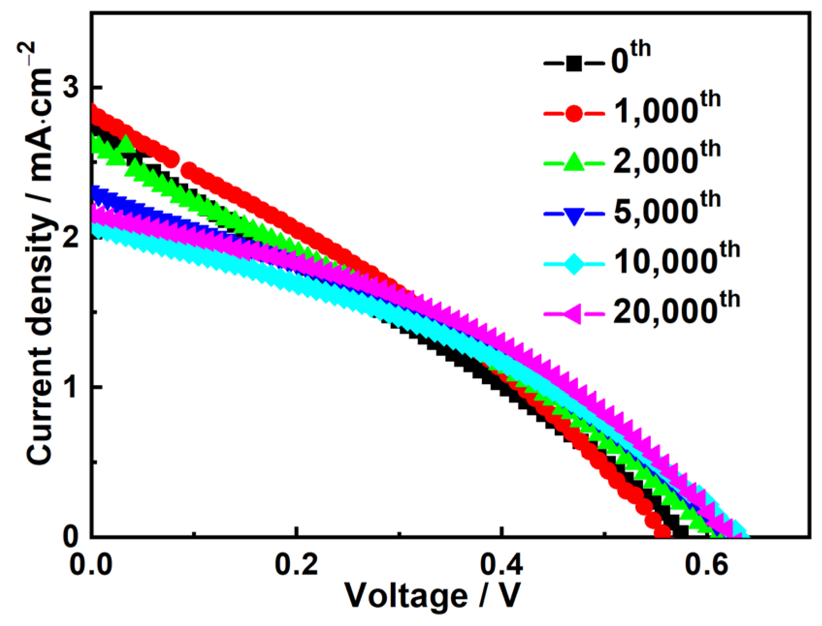
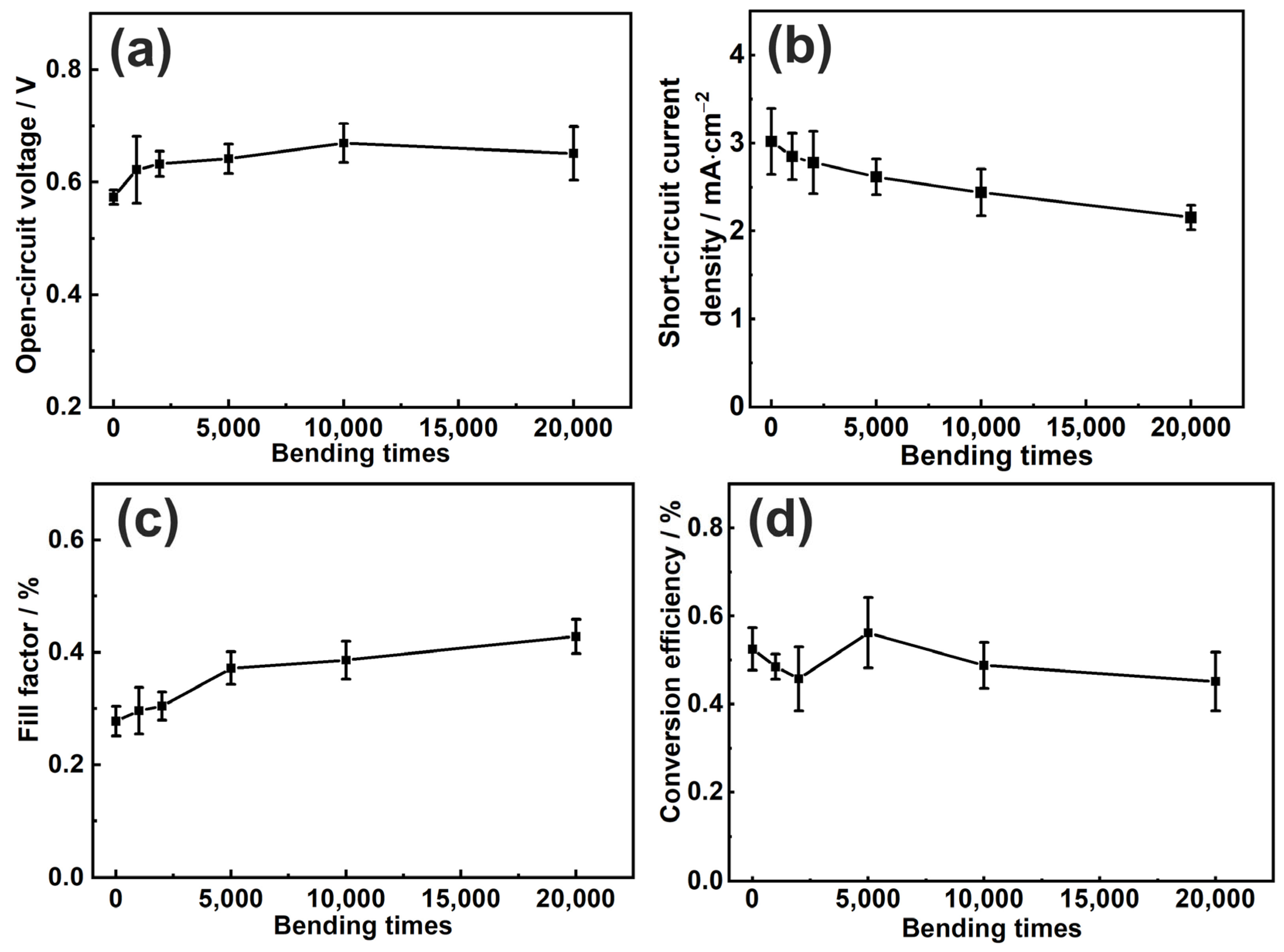
After the flexible all-solid-state DSCs are assembled, the bending-resistant ability of the solar cells is tested. The short-circuit current density (Jsc), open-circuit voltage (Voc), fill factor (FF), and conversion efficiency (η) of five cells with the same bending process are detected. Figure 5 shows the photovoltaic performance of the solar cells at the recovery state after 0, 1000, 2000, 5000, 10,000, and 20,000 bending times, and the bending radius is chosen as 8 mm during the whole testing process. It can be seen that the original performance data are Voc of 0.57 V, Jsc of 2.81 mA·cm−2, FF of 0.30, and η of 0.49%; and during 20,000 bending times, the Jsc, Voc, FF, and η all show a certain amount of change because of the change in the inner structure. When the parameters in Jsc, Voc, FF, and η are separately shown according to the bending times in Figure 6, it can be seen more intuitively that the Voc and FF of the solar cells increase slightly, while the Jsc of the solar cells continue to decrease with an increase in bending times. At last, the η almost remains constant during the 20,000 bending processes. Compared with the liquid solar cells that have been reported, the flexible all-solid DSCs show good bending-resistant ability.
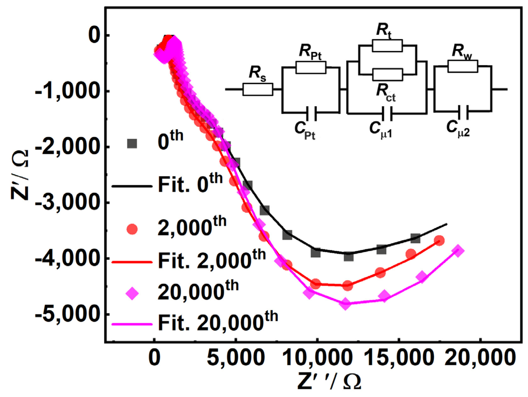
To find out why there is a certain amount of change for the photovoltaic parameters during the bending processes, the electrochemical impedance spectroscopy (EIS) of the solar cell with increasing bending times is tested at the Voc under illumination. Figure 7 shows the Nyquist plots of the flexible all-solid-state DSCs under the conditions of 0, 1000, and 20,000 bending times, respectively. There are three semicircles in the impedance curves from the high-frequency zone (105–103 Hz) to the middle-frequency zone (103–101 Hz) and the low-frequency zone (101–10−1 Hz) from left to right; the catalytic reduction ability of Pt electrode is represented by the semicircle at the high-frequency zone, the electron transportation and recombination ability of TiO2/N719/electrolyte are represented by the semicircle at the middle-frequency zone, and the charge diffusion ability of I−/I3− for the electrolyte is represented by the semicircle at the low-frequency zone [28,29] It can be seen from Figure 7 that with an increase in bending times, there is no significant change for the semicircles at the high-frequency and middle-frequency zones, whereas the semicircle at the low-frequency zone shows an obvious change.
A generalized equivalent circuit model [30,31,32] shown in the inset of Figure 7 is employed to fit the EIS spectrum, the detailed data are shown in Table 1, where the Rpt represents the catalytic resistance of the Pt electrode; Rt represents the transport resistance of electrons in the TiO2 film; Rct represents the charge recombination resistance at the TiO2/N719/electrolyte interface, and Rw represents the diffusion resistance of I−/I3− in the polymer electrolyte. It can be seen with increasing bending times that Rpt, Rt, and Rct are almost constant; however, the charge diffusion resistance Rw increases from 1280 Ω to 1500 Ω, which indicates that the structure of Pt electrode, TiO2 film, and the TiO2/N719/electrolyte is stable, whereas the structure of the polymer electrolyte may be deteriorated. That is to say, during the bending process, the photoanode of the solar cells is stable due to the increasing bending-resistant ability coming from the designed dual-porous TiO2 film and polymer electrolyte filling state. Though bending causes changes in the electrolyte, based on the research on liquid flexible DSCs, we will try to manipulate the neural layer at the electrolyte region to achieve bending resistance for the entire structure in the future.
4. Conclusions
In this study, the dual-porous TiO2 film is obtained by spraying micron-sized composite clusters to replace the traditional nano-porous film, and besides the nanopores, the nickel-plating results show that there are submicron pores. After the polymer electrolyte is infiltrated into the dual-porous film, the solvent is removed quickly by vacuum drying, and then the PVDF/PEO-based electrolyte is not only coated on the surface of the TiO2 particles but also forms fibers in the submicron pores. When the designed photoanodes, including the dual-porous TiO2 film and the polymer electrolyte filling state, are assembled into flexible all-solid-state DSCs, the solar cells show a bending-resistant ability during the bending process. The total conversion efficiency of the designed solar cells is almost constant during the 20,000 bending times because of the improved stress release ability, and the EIS results show that the change in the electrolyte structure may result in a change in individual photovoltaic parameters. The research illustrates that increasing the stress release space (submicron pores) and introducing elastic material (polymer electrolyte and electrolyte fiber) in the TiO2 film improves the bending-resistant ability of the photoanode of the all-solid-state DSCs.
Supplementary Materials
The following are available online at https://www.mdpi.com/article/10.3390/coatings14040504/s1, Figure S1: The high magnification SEM morphology data of the dual-porous film.
Author Contributions
Conceptualization, Y.L. and W.-W.D.; methodology, Y.L.; validation, Y.L., Y.-X.H. and W.-W.D.; formal analysis, Y.-X.H. and L.L.; investigation, Y.-X.H. and L.L.; resources, Y.L. and W.-W.D.; data curation, L.L., J.-H.C. and X.G.; writing—original draft preparation, Y.L.; writing—review and editing, Y.L. and W.-W.D. All authors have read and agreed to the published version of the manuscript.
Funding
This project was supported by the National Natural Science Foundation of China (Grant No. 62204202), Natural Science Foundation of Shaanxi Province (Grant No. 2024JC-YBMS-438), the Open Project Program of Key Laboratory of Functional Materials and Devices for Informatics of Anhui Higher Education Institutes (Fuyang Normal University) (Grant No. FSKFKT007), The Key Research and Development Program of Shaanxi Program (Grant No. 2023KXJ-172), and the 2024 Scientific research project of Shaanxi Institute of Technology (Grant No. Gfy24-04).
Institutional Review Board Statement
Not applicable.
Informed Consent Statement
Not applicable.
Data Availability Statement
Data are contained within the article and Supplementary Materials.
Conflicts of Interest
The authors declare no conflicts of interest.
References
- Sekaran, P.D.; Marimuthu, R. An extensive analysis of dye-sensitized solar cell (DSSC). Brazilian J. Phys. 2024, 54, 28. [Google Scholar] [CrossRef]
- Wrede, S.; Cai, B.; Cheng, F.W.; Johansson, M.B.; Kubart, T.; Hägglund, C.; Tian, H.N. A solid-state p-n tandem dye-sensitized solar cell. Sustain. Energ. Fuel. 2024, 8, 1004–1011. [Google Scholar] [CrossRef]
- Wu, T.-C.; Huang, W.-M.; Tsai, J.-K.; Chang, C.-E.; Meen, T.-H. Effect of photoanode process sequence on efficiency of dye-sensitized solar cells. Coatings 2024, 14, 304. [Google Scholar] [CrossRef]
- Mohamad, A.A. Physical properties of quasi-solid-state polymer electrolytes for dye-sensitised solar cells: A characterisation review. Sol. Energ. 2019, 190, 434–452. [Google Scholar] [CrossRef]
- Grätzel, M. Dye-sensitized solar cells. J. Photoch. Photobio. C 2003, 4, 145–153. [Google Scholar] [CrossRef]
- Kamat, P.V. Quantum dot solar cells. The next big thing in photovoltaics. J. Phys. Chem. Lett. 2013, 4, 908–918. [Google Scholar] [CrossRef] [PubMed]
- Kojima, A.; Teshima, K.; Shirai, Y.; Miyasaka, T. Organometal halide perovskites as visible-light sensitizers for photovoltaic cells. J. Am. Chem. Soc. 2009, 131, 6050–6051. [Google Scholar] [CrossRef] [PubMed]
- Zhang, D.; Yoshida, T.; Minoura, H. Low-temperature fabrication of efficient porous titania photoelectrodes by hydrothermal crystallization at the solid/gas interface. Adv. Mater. 2003, 15, 814–817. [Google Scholar] [CrossRef]
- Lindström, H.; Magnusson, E.; Holmberg, A.; Södergren, S.; Lindquist, S.-E.; Hagfeldt, A. A new method for manufacturing nanostructured electrodes on glass substrates. Sol. Energy Mater. Sol. Cells 2002, 73, 91–101. [Google Scholar] [CrossRef]
- Miyasaka, T.; Kijitori, Y.; Murakami, T.N.; Kimura, M.; Uegusa, S. Efficient nonsintering type dye-sensitized photocells based on electrophoretically deposited TiO2 layers. Chem. Lett. 2002, 31, 1250–1251. [Google Scholar] [CrossRef]
- Han, H.-G.; Weerasinghe, H.C.; Min Kim, K.; Soo Kim, J.; Cheng, Y.-B.; Jones, D.J.; Holmes, A.B.; Kwon, T.-H. Ultrafast fabrication of flexible dye-sensitized solar cells by ultrasonic spray-coating technology. Sci. Rep. 2015, 5, 14645. [Google Scholar] [CrossRef] [PubMed]
- Kijitori, Y.; Ikegami, M.; Miyasaka, T. Highly efficient plastic dye-sensitized photoelectrodes prepared by low-temperature binder-free coating of mesoscopic titania pastes. Chem. Lett. 2007, 36, 190–191. [Google Scholar] [CrossRef]
- Chen, H.-W.; Hsu, C.-Y.; Chen, J.-G.; Lee, K.-M.; Wang, C.-C.; Huang, K.-C.; Ho, K.-C. Plastic dye-sensitized photo-supercapacitor using electrophoretic deposition and compression methods. J. Power Sources 2010, 195, 6225–6231. [Google Scholar] [CrossRef]
- Shao, J.; Liu, F.; Dong, W.; Tao, R.; Deng, Z.; Fang, X.; Dai, S. Low temperature preparation of TiO2 films by cold isostatic pressing for flexible dye-sensitized solar cells. Mater. Lett. 2012, 68, 493–496. [Google Scholar] [CrossRef]
- He, X.-L.; Yang, G.-J.; Li, C.-J.; Li, C.-X.; Fan, S.-Q. Room temperature cold sprayed TiO2 scattering layer for high performance and bending resistant plastic-based dye-sensitized solar cells. J. Power Sources 2014, 251, 122–129. [Google Scholar] [CrossRef]
- He, X.-L.; Liu, M.; Yang, G.-J.; Yao, H.-L.; Fan, S.-Q.; Li, C.-J. Photovoltaic performance degradation and recovery of the flexible dye-sensitized solar cells by bending and relaxing. J. Power Sources 2013, 226, 173–178. [Google Scholar] [CrossRef]
- Chung, I.; Lee, B.; He, J.; Chang, R.P.H.; Kanatzidis, M.G. All-solid-state dye-sensitized solar cells with high efficiency. Nature 2012, 485, 486–489. [Google Scholar] [CrossRef]
- Zhang, L.; Boschloo, G.; Hammarström, L.; Tian, H. Solid state p-type dye-sensitized solar cells: Concept, experiment and mechanism. Phys. Chem. Chem. Phys. 2016, 18, 5080–5085. [Google Scholar] [CrossRef]
- Manceriu, L.; Bharwal, A.K.; Daem, N.; Dewalque, J.; Colson, P.; Boschini, F.; Cloots, R. Printability of (quasi-) solid polysiloxane electrolytes for online dye-sensitized solar cell fabrication. Coatings 2023, 13, 1164. [Google Scholar] [CrossRef]
- Li, Y.; He, X.-L.; Lian, C.-X.; Yao, H.-L.; Yang, G.-J.; Li, C.-X.; Li, C.-J.; Fang, B. In situ formation of continuous charge transfer pathways for highly efficient, solvent-free, polymer electrolyte-based dye-sensitized solar cells. ACS Sustain. Chem. Eng. 2016, 4, 4013–4020. [Google Scholar] [CrossRef]
- Li, C.; Luo, Y.; Guo, X.; Li, D.; Mi, J.; Sø, L.; Hald, P.; Meng, Q.; Iversen, B.B. Mesoporous TiO2 aggregate photoanode with high specific surface area and strong light scattering for dye-sensitized solar cells. J. Solid State Chem. 2012, 196, 504–510. [Google Scholar] [CrossRef]
- Zhu, F.; Wu, D.; Li, Q.; Dong, H.; Li, J.; Jiang, K.; Xu, D. Hierarchical TiO2 microspheres: Synthesis, structural control and their applications in dye-sensitized solar cells. RSC Adv. 2012, 2, 11629–11637. [Google Scholar] [CrossRef]
- Chen, D.; Huang, F.; Cheng, Y.-B.; Caruso, R.A. Mesoporous anatase TiO2 beads with high surface areas and controllable pore sizes: A superior candidate for high-performance dye-sensitized solar cells. Adv. Mater. 2009, 21, 2206–2210. [Google Scholar] [CrossRef]
- He, X.-L.; Yang, G.-J.; Li, C.-J.; Li, C.-X. Influence of accelerating gas flow rate on the particle cohesion in room temperature cold sprayed scattering layer for plastic-based dye-sensitized solar cells. Appl. Surf. Sci. 2014, 288, 416–422. [Google Scholar] [CrossRef]
- Yang, G.-J.; Liao, K.-X.; Li, C.-J.; Fan, S.-Q.; Li, C.-X.; Li, S. Formation of pore structure and its influence on the mass transport property of vacuum cold sprayed TiO2 coatings using strengthened nanostructured powder. J. Therm. Spray Technol. 2012, 21, 505–513. [Google Scholar] [CrossRef]
- Yang, G.-J.; Li, C.-J.; Fan, S.-Q.; Gao, J.-C. Influence of pore structure on ion diffusion property in porous TiO2 coating and photovoltaic performance of dye-sensitized solar cells. Surf. Coatings Technol. 2011, 205, 3205–3210. [Google Scholar] [CrossRef]
- Zaine, S.N.A.; Mohamed, N.M.; Khatani, M.; Shahid, M.U. Enhancement of charge transport of a dye-sensitized solar cell utilizing TiO2 quantum dot photoelectrode film. Coatings 2021, 11, 1442. [Google Scholar] [CrossRef]
- Al-Attafi, K.; Dwech, M.H.; Mezher, H.A.; Nattestad, A.; Kim, J.H. A Comparative study of organic dye-sensitized solar cells based on anatase TiO2 and amorphous free mixed phase’s anatase/rutile P25 TiO2 photoanodes. Coatings 2023, 13, 121. [Google Scholar] [CrossRef]
- Wu, T.C.; Huang, W.M.; Meen, T.H.; Tsai, J.K. Performance improvement of dye-sensitized solar cells with pressed TiO2 nanoparticles layer. Coatings 2023, 13, 907. [Google Scholar] [CrossRef]
- Bisquert, J. Theory of the impedance of electron diffusion and recombination in a thin layer. J. Phys. Chem. B 2002, 106, 325–333. [Google Scholar] [CrossRef]
- Fabregat-Santiago, F.; Bisquert, J.; Garcia-Belmonte, G.; Boschloo, G.; Hagfeldt, A. Influence of electrolyte in transport and recombination in dye-sensitized solar cells studied by impedance spectroscopy. Sol. Energy Mater. Sol. Cells 2005, 87, 117–131. [Google Scholar] [CrossRef]
- Fabregat-Santiago, F.; Bisquert, J.; Palomares, E.; Otero, L.; Kuang, D.; Zakeeruddin, S.M.; Gratzel, M. Correlation between photovoltaic performance and impedance spectroscopy of dye-sensitized solar cells based on ionic liquids. J. Phys. Chem. C 2007, 111, 6550–6560. [Google Scholar] [CrossRef]
Figure 1.
The microstructure of the powder and composite film: (a) the pristine P25 powder, (b) the composite cluster after annealing, and (c) the cross-sectional view of the dual-porous film.
Figure 1.
The microstructure of the powder and composite film: (a) the pristine P25 powder, (b) the composite cluster after annealing, and (c) the cross-sectional view of the dual-porous film.
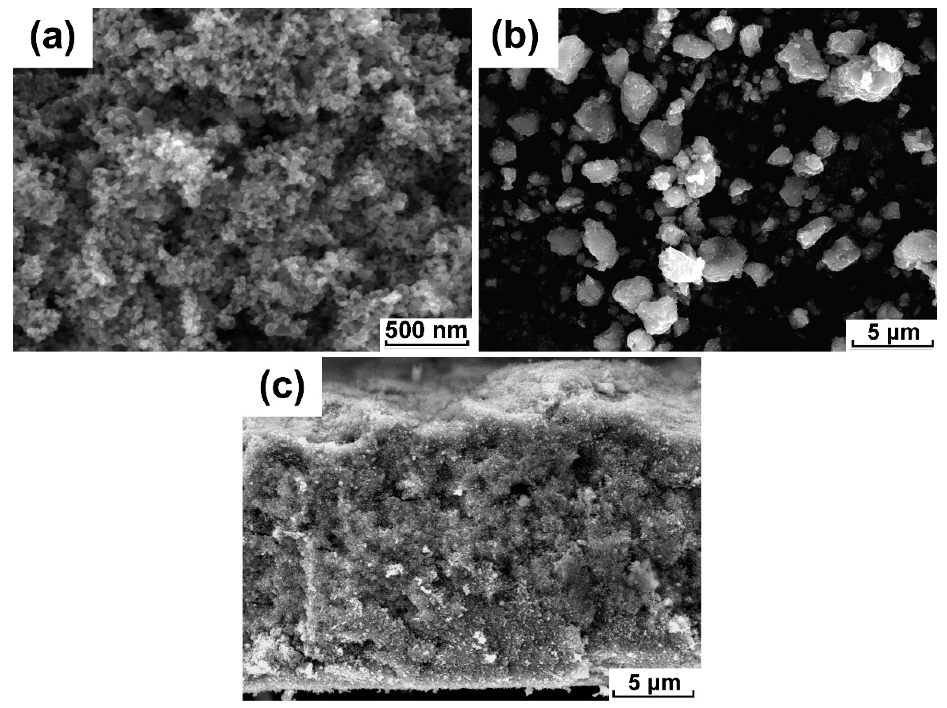
Figure 2.
The cross-sectinal view of the dual-porous film after electroplate nickel: (a) distribution and (b) particle size.
Figure 2.
The cross-sectinal view of the dual-porous film after electroplate nickel: (a) distribution and (b) particle size.
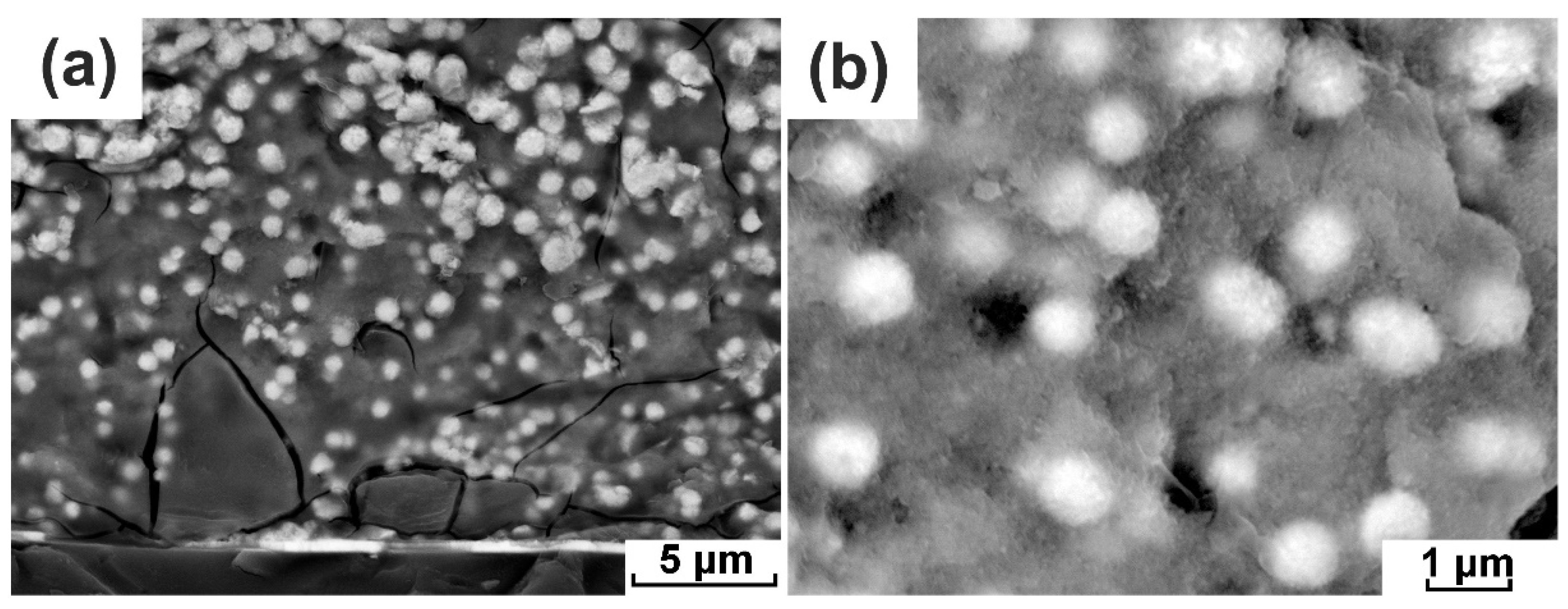
Figure 3.
The cross-sectional view of the dual-porous film after being filled with PVDF/PEO-based electrolyte: (a) low magnification and (b) high magnification, and the obvious electrolyte fibers are marked with black arrows.
Figure 3.
The cross-sectional view of the dual-porous film after being filled with PVDF/PEO-based electrolyte: (a) low magnification and (b) high magnification, and the obvious electrolyte fibers are marked with black arrows.
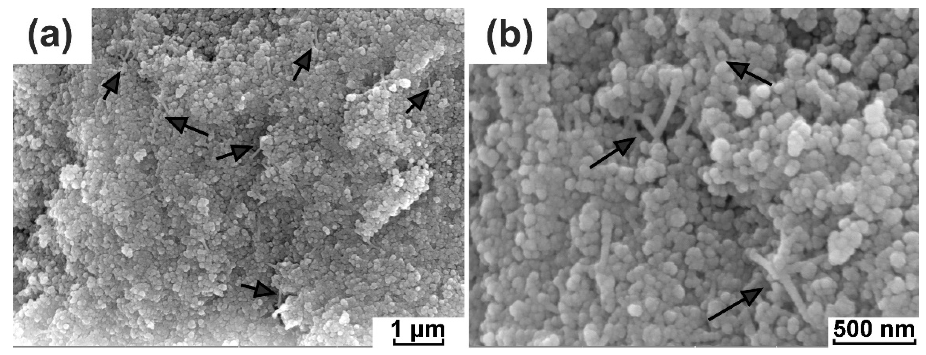
Figure 4.
The formation process of the electrolyte fiber on dual-porous film: (a) the electrolyte solution fully infiltrates the submicron pore, (b) the PVDF/PEO solute shrank to the TiO2 film along with the evaporation of the solvent, and (c) the electrolyte undergoes in-situ solidification into a fiber because of the fast evaporation of the solvent. The blue particles represent TiO2 and the electrolyte filling in the TiO2 film is represented by yellow.

Figure 5.
The photovoltaic performance of the flexible all-solid-state solar cell under the bending times of 0th, 1000th, 2000th, 5000th, 10,000th, and 20,000th.
Figure 5.
The photovoltaic performance of the flexible all-solid-state solar cell under the bending times of 0th, 1000th, 2000th, 5000th, 10,000th, and 20,000th.

Figure 6.
The variation tendency of the photovoltaic parameters for an average of 5 solar cells with increasing bending times: (a) Voc, (b) Jsc, (c) FF, and (d) η, where Voc is short for open-circuit voltage; Jsc is short for short-circuit current density; FF is short for fill factor, and η is short for conversion efficiency.

Figure 7.
The typical Nyquist plots of the flexible all-solid-state DSCs under bending times of 0, 2000, and 20,000 at Voc under illumination. The dots are the pristine data, and the solid lines are the fitting results based on the equivalent circuit model shown in the inset. In the equivalent circuit model, Rs is the series resistance including the sheet resistance of the whole cell; RPt and CPt are the charge transfer resistance and electrical double-layer capacitance at the Pt/electrolyte interface; Rt is the transport resistance of the electrons in TiO2 film, and Rct is the charge transfer resistance of electrons at the TiO2/dye/electrolyte interface; Cμ1 is the chemical capacitance of TiO2 film; Rw and Cμ2 are the charge diffusion resistance and chemical capacitance of the electrolyte.


Table 1.
The detailed Nyquist plot data of the flexible all-solid-state DSC after bending times of 0, 2000, and 20,000.
Table 1.
The detailed Nyquist plot data of the flexible all-solid-state DSC after bending times of 0, 2000, and 20,000.
| Bending Times | Rt/Ω | Rct/×103 Ω | Rw/×103 Ω |
|---|---|---|---|
| 0 | 10.7 | 1.79 | 1.28 |
| 1000 | 11.9 | 1.80 | 1.35 |
| 20,000 | 11.0 | 1.79 | 1.50 |
Disclaimer/Publisher’s Note: The statements, opinions and data contained in all publications are solely those of the individual author(s) and contributor(s) and not of MDPI and/or the editor(s). MDPI and/or the editor(s) disclaim responsibility for any injury to people or property resulting from any ideas, methods, instructions or products referred to in the content. |
© 2024 by the authors. Licensee MDPI, Basel, Switzerland. This article is an open access article distributed under the terms and conditions of the Creative Commons Attribution (CC BY) license (https://creativecommons.org/licenses/by/4.0/).
Share and Cite
MDPI and ACS Style
Li, Y.; Hou, Y.-X.; Dang, W.-W.; Liu, L.; Chen, J.-H.; Gu, X. Design and Preparation of Bending-Resistant Flexible All-Solid Dye-Sensitized Solar Cells. Coatings 2024, 14, 504. https://doi.org/10.3390/coatings14040504
AMA Style
Li Y, Hou Y-X, Dang W-W, Liu L, Chen J-H, Gu X. Design and Preparation of Bending-Resistant Flexible All-Solid Dye-Sensitized Solar Cells. Coatings. 2024; 14(4):504. https://doi.org/10.3390/coatings14040504
Chicago/Turabian StyleLi, Yan, Yu-Xuan Hou, Wei-Wu Dang, Li Liu, Jian-Hua Chen, and Xian Gu. 2024. "Design and Preparation of Bending-Resistant Flexible All-Solid Dye-Sensitized Solar Cells" Coatings 14, no. 4: 504. https://doi.org/10.3390/coatings14040504
Note that from the first issue of 2016, this journal uses article numbers instead of page numbers. See further details here.