
Fabrication of Nanostructures Consisting of Composite Nanoparticles by Open-Air PLD
by
 , , , ,
Anna Og Dikovska
1,*,
Daniela Karashanova
2,
Genoveva Atanasova
3,
Georgi Avdeev
4,
Petar Atanasov
1 and
Nikolay N. Nedyalkov
1 1
Institute of Electronics, Bulgarian Academy of Sciences, 72 Tsarigradsko Chaussee, 1784 Sofia, Bulgaria
2
Institute of Optical Materials and Technologies “Acad. J. Malinowski”, Bulgarian Academy of Sciences, Acad. G. Bonchev Str., bl. 109, 1113 Sofia, Bulgaria
3
Institute of General and Inorganic Chemistry, Bulgarian Academy of Sciences, Acad. G. Bonchev Str., bl. 11, 1113 Sofia, Bulgaria
4
Rostislaw Kaischew Institute of Physical Chemistry, Bulgarian Academy of Sciences, Acad. G. Bonchev Str., bl. 11, 1113 Sofia, Bulgaria
*
Author to whom correspondence should be addressed.
Coatings 2024, 14(5), 527; https://doi.org/10.3390/coatings14050527
Submission received: 19 March 2024
/
Revised: 13 April 2024
/
Accepted: 22 April 2024
/
Published: 24 April 2024
(This article belongs to the Special Issue Advances in Metal Matrix Composite Coatings and Layers: Microstructure, Physicochemical and Mechanical Properties)
Abstract
:We present a two-step physical method for the fabrication of composite nanoparticle-based nanostructures. The proposed method is based on the pulsed laser deposition (PLD) technique performed sequentially in vacuum and in air. As a first step, thin-alloyed films of iron with noble metal were deposited by PLD in vacuum. The films were prepared by ablation of a mosaic target formed by equal iron and gold sectors. As a second step, the as-prepared alloyed films were ablated in air at atmospheric pressure as the laser beam scanned their surface. Two sets of experiments were performed in the second step, namely, by applying nanosecond (ns) and picosecond (ps) laser pulses for ablation. The structure, microstructure, morphology, and optical properties of the samples obtained were studied with respect to the laser ablation regime applied. The implementation of the ablation process in open air resulted in the formation of nanoparticle and/or nanoparticle aggregates in the plasma plume regardless of the ablation regime applied. These nanoparticles and/or nanoaggregates deposited on the substrate formed a complex porous structure. It was found that ablating FeAu films in air by ns pulses resulted in the fabrication of alloyed nanoparticles, while ablation by ps laser pulses results in separation of the metals in the alloy and further oxidation of Fe. In the latter case, the as-deposited structures also contain core–shell type nanoparticles, with the shell consisting of Fe-oxide phase. The obtained structures, regardless of the ablation regime applied, demonstrate a red-shifted plasmon resonance with respect to the plasmon resonance of pure Au nanoparticles.
1. Introduction
Iron-oxide-containing magnetic nanoparticles and nanostructures have found a variety of practical applications, including high-density data storage media, electronic elements and sensors, and controlled drug delivery and cancer diagnostics/treatment systems [1,2,3,4,5,6]. Magnetite as well as maghemite, because of their unique physical properties in nanosized form, are among the most investigated oxides, with numerous current and potential applications. These oxides exhibit unique magnetic properties, biocompatibility, and biodegradability, which in turn make them suitable for biomedical application [2,3,7]. Such uses usually require a specific size distribution and a desired shape of the nanoparticles or ensembles of nanoparticles, since these define their magnetic properties and, respectively, their efficiency. This is why such nanosized objects should be fabricated through precise size- and shape-controlling synthesis, on the one hand, and, if possible, without the use of additional toxic chemicals, on the other. In general, conventional approaches such as chemical, template-assisted, and lithographic have been extensively investigated and applied for fabrication of a wide variety of magnetic nanostructures such as iron oxides, pure metals, metal alloys, and core–shell structures [2,3,4,8,9,10,11]. Therefore, the challenge and the efforts of scientists and engineers are focused on devising ways of environmentally friendly fabrication of magnetic nanoparticles or nanostructures, utilizing simple and flexible methods and conventional low-cost equipment.
Pulsed laser deposition is a well-established physical method for fabrication of thin films and structures based on laser ablation of a target material [12]. When the process is performed in the air at atmospheric pressure (PLD in open air or atmospheric PLD), the ablated material directly forms nanoparticles in the plasma plume [13,14]. The method has been successfully applied for production of oriented nanowires of magnetic materials [15,16]. Further, the proposed method is easily modified for fabrication of more complicated systems such as composite nanostructures made of magnetic and nonmagnetic materials [17,18]. This technology was developed and applied for ultrashort (ps and fs) and later for short (ns) laser pulses [15,19,20]. The main difference between short and ultrashort ablation in open air is that, in the case of ns-laser pulses, the nanoparticles are formed via condensation of ablated material [15,16], while using ultrashort laser pulses leads to a direct ejection of nanoparticles thanks to the specific mechanisms of material removal [19,20,21]. The PLD technology in open air is generally applied for ablation of bulk target material. However, the same technology could also be applied if the bulk target material is replaced by a thin film deposited from the desired material in advance. The laser ablation of thin films is an area of rapidly growing interest. Numerous researchers have focused their efforts on clean micropatterning of thin films or selective ablation of metal films, even in the case of complicated multilayer structures [22,23,24,25]. Such application of laser ablation on thin films requires the use of ultrashort laser pulses for precise processing of the materials. Also, this technology has been successfully applied for fabrication of nanoparticles and/or nanostructures in liquid [16,17,18,19,20,21,22,23,24,25,26,27,28]. In general, optical absorption, thermal, and structural properties of the film, and adhesion to the substrate influence and determine the ablation process. The mechanism of synthesis as well as the advantages and possible applications of a variety of complex materials and structures produced in liquid are summarized by Amendola et al. [26]. Similarly, laser ablation from a thin-film target performed in air could be used for production of nanoparticles and nanoaggregates on a substrate. In the latter case, the attention will be focused on the material removed by the ablation of the thin film. The advantage of using a thin-film target versus a bulk target stands out for the materials for which preparation as bulk material is a hard and/or expensive task, for example, the fabrication of bulk alloyed targets from hardly miscible, as well as expensive, metals such as iron and noble metals. Fe has a body-centered cubic cell (bcc), while noble metals have a face-centered cubic cell (fcc). Such metal alloyed thin films with a desirable thickness could be easily and less expensively fabricated by well-developed conventional technologies for thin film synthesis.
Ultrashort pulse lasers, especially fs lasers, are yet to find wide industrial applications because of their high price, expensive maintenance, and specific requirements to the working environment. Picosecond laser systems with a pulse duration of up to tens of picoseconds, at the same time, are of considerable scientific and commercial interest. The ps-laser pulses preserve the primary features of fs-laser pulses regarding their interaction with the material. The picosecond laser systems are simpler and more stable than fs-laser systems, leading to their lower cost, which is comparable to that of popular and widely used nanosecond systems. Such lasers could be easily applied in industries. Using ps pulses in PLD will allow for even wider commercial applications due to maintaining the process characteristics of ultrashort laser–matter interaction.
In this work, we aimed to fabricate nanostructures consisting of composite nanoparticles of iron-containing alloy, namely FeAu alloy, by implementing a physical method such as PLD in open air. We studied the material removed from a thin-film target when laser ablation was performed by nanosecond and by picosecond laser pulses. We were thus able to emphasize the differences in the structure, microstructure, and morphology of the structures produced by ns and ps ablation. It was found that nanostructures composed of alloyed nanoparticles were produced by ns ablation of thin FeAu film, while ablation by ps laser pulses resulted, rather, in separation of the alloy into Au and Fe metals, and further oxidation of iron to oxide phase. In the latter case, the fabricated nanoparticles had a clearly expressed bimodal size distribution, as larger-sized particles exhibited a core–shell type structure with an Fe-oxide phase as a shell. The obtained structures, regardless of the ablation regime applied, demonstrated a plasmon resonance related to the presence of Au or Au-containing nanoparticles. Further, since the ablation from a thin-film target is a specific case of laser–matter interaction where the geometric parameters of the film could significantly influence the processes involved, we performed a numerical simulation of laser–matter interaction with ns and ps laser pulses. A theoretical study of the temporal temperature distribution on the film surface and film substrate was also carried out to clarify the potential for application of the presented technology.
2. Materials and Methods
2.1. Experimental
Nanostructures consisting of composite nanoparticles were produced by a two-step physical deposition method. It was based on pulsed laser deposition (PLD) performed sequentially in vacuum and in air. A schematic view of the experimental setup is shown in Figure 1. As a first step, thin films were deposited by classical on-axis PLD in a vacuum.
The depositions were implemented using a nanosecond Nd: YAG laser emitting at its third harmonic wavelength, 355 nm, with 15 ns pulse duration and 10 Hz repetition rate. The laser fluence applied on the target was 4 J/cm2. A pure iron target or a mosaic target formed by iron and gold metal equal sectors was used for ablation. The ablated material was deposited on a glass substrate. The experiments were conducted at a target–substrate distance of 30 mm at room substrate temperature and a base pressure of 10−4 Torr. All depositions were performed for 15 min. Under these conditions, the maximum measured film thickness was approximately 300 nm. As a second step, the as-prepared thin films were ablated in air at atmospheric pressure (in open air) as the laser beam scanned their surface. The speed of the X–Y scan table was chosen so as to prevent the laser spots from overlapping. Two sets of experiments were performed in the second step based on ablation with nanosecond (ns) and picosecond (ps) laser pulses, respectively. The ns ablation was performed by a Nd: YAG (LS-2147, Lotis TII, Minsk, Belarus) laser system delivering 15 ns laser pulses. The ps ablation was carried out by a picosecond Nd: YAG laser (PS-A1-1064, CNL laser, Changchun, China) with a pulse duration of 10 ps. In both cases, the third harmonic frequency of Nd: YAG lasers at wavelength of 355 nm was used with a 10 Hz repetition rate. The laser fluence applied on the thin films for ns and ps ablation was 1.5 J/cm2 and 0.8 J/cm2, respectively. The ablated material was deposited on a silicon or quartz substrate at room substrate temperature. The distance between the target and substrate was kept at 5 mm. Further, using the experimental configuration shown in Figure 1, additional experiments were performed on ns and ps ablation of a bulk Fe in order to compare samples deposited from bulk and thin-film targets.
2.2. Theoretical
In order to estimate the heating evolution and the spatial distribution of the temperature during laser processing of the thin film, as used in the experimental part, a numerical model was applied. For the case of ablation with nanosecond pulse, a one-dimensional heat diffusion equation was applied:
The source term is S(z,t) = I(t)(1 − R)α exp(−αz), where R is the reflectivity of the material and I is the laser intensity. C = cρ, where c and ρ are the specific heat capacity and material density, respectively, k is the thermal conductivity, and α is the absorption coefficient. The laser intensity is considered to be Gaussian in time; z is the coordinate in the direction parallel to the film surface normal.
In the case of ps ablation, a two-temperature model was applied. It takes into account that during the time of the laser pulse duration, the electron system in the film absorbs the laser energy and its temperature increases rapidly. At the same time, the lattice temperature remains close to the initial one since the time for energy transfer between the electrons and the lattice is of the same order as the pulse duration. The model solves the head diffusion equations for both systems:
where the notations are the same as in Equation (1); γ is the electron–phonon coupling parameter, Te and Ti are the temperatures of the election and lattice systems, respectively; C and k are the heat capacity and the thermal conductivity for both systems. Equation (1) and System (2) were solved using a classical finite difference scheme [29], as the simulated system was divided into slices in z direction with a thickness of 1 nm. The parameters for Fe used in the model were taken from Refs. [30,31,32]. The reflection of the film was estimated to be 60% using optical transmission measurement.
2.3. Sample Characterization
The crystalline structure and phase composition of the samples were analyzed by an Empyrean diffractometer (PANalytical, Malvern, UK) through a goniometric X-ray diffraction scan using CuKα radiation. Bright field transmission electron microscopy (BF TEM) and high-resolution (HR) TEM images, and selected area electron diffraction (SAED) patterns were taken by a JEOL JEM 2100 microscope (Akishima-Shi, JEOL Ltd., Tokyo, Japan) to reveal the samples’ microstructure and their crystallinity. Samples for TEM analyses were prepared using a direct deposition on carbon-coated TEM Cu grids for a shorter deposition time (3 min) to prevent the ablated materials overlapping. Scanning electron microscopy (SEM) equipped with an energy-dispersive X-ray (EDX) spectrometer was conducted using a LYRA I XMU system (Tescan, Brno, Czech Republic) to study the samples’ morphology. The physicochemical state of the sample surface was determined by X-ray photoelectron spectroscopy (XPS) using an AXIS Supra electron spectrometer (Kratos Analytical Ltd., Manchester, UK). The optical properties of the samples were investigated using light from a standard white-light source (DH-2000 Ocean Insight, Dunedin, FL, USA) transmitted through the sample and recorded by a UV–Vis spectrometer (Ocean Optics HR 4000, Ocean Insight, Dunedin, FL, USA).
3. Results
3.1. Experimental
In view of clarifying the processes taking place and for further comparison, experiments were initially performed on laser ablation of a bulk Fe target using the experimental configuration shown in Figure 1. The results obtained from ns and ps laser ablation from bulk Fe, thin Fe, and FeAu alloyed film are discussed below.
3.1.1. Laser Ablation of Bulk Fe
TEM images of the samples deposited by laser ablation of bulk Fe are shown in Figure 2. The microstructure and the phase composition of the samples produced by ns ablation of iron are presented in Figure 2a. Separated and aggregated nanoparticles were produced by direct deposition on the substrate using the experimental configuration shown in Figure 1 at II stage. As seen, the nanoparticles are well-defined and spherically shaped with size distribution in the range of 3–12 nm and a mean Ferret’s diameter of 7 nm. This result is in accordance with previous reports on ns laser ablation in open air [18]. The nanoparticles are crystalline, as seen from the SAED image in Figure 2a, with interplanar distances predominantly identified as appropriate of the magnetite phase of the iron oxide (Fe3O4, cubic, a = 8.4000 Å, 98-003-6314). Figure 2b reports the microstructure of the sample deposited by ps ablation of bulk Fe. In this case, the ablated material is represented mostly by agglomerated nanoparticles with sizes between 1 and 7 nm and a mean Ferret’s diameter of 3 nm. The shape of the nanoparticles is close to spherical. The SAED pattern presented in Figure 2b shows that the sample has a polycrystalline structure, and the pattern was assigned to the maghemite phase of iron oxide (ϒ-Fe2O3, tetragonal, a = 8.33200 Å c = 25.11300 Å, 96-152-8613).
3.1.2. Laser Ablation of Pure Fe Film
TEM images of the samples deposited by laser ablation of thin Fe films are presented in Figure 3. The morphology of the sample deposited by ns ablation is shown in Figure 3a. As seen, ns ablation of thin films in air at atmospheric pressure leads to direct formation of nanoparticles. Similar results were already reported and discussed for ns ablation of a bulk target [15,16,18]. The morphology reveals that the nanoparticles formed have a polygonal shape, with most of them having a size in the range of 2–20 nm, as seen from the size distribution. The mean diameter of the nanoparticles was estimated to be 10 nm with a standard deviation (SD) of 4.2 (Figure 3a). The nanoparticles are crystalline, as demonstrated from the SAED pattern presented in Figure 3a. The SAED pattern indexation reveals the formation of iron oxide phase magnetite. It should be mentioned that no core–shell structure was observed in the fabricated nanoparticles, regardless of their size. TEM images of the sample deposited using ps ablation are shown in Figure 3b. As with the ns pulses, laser ablation of thin films with ps laser pulses in open air caused formation of nanoparticles. In the case of ps ablation, the microstructure of the sample consisted of spherical as well as polygon-shaped nanoparticles. There were clearly distinguishable particles with sizes from approximately 20 nm to 100 nm, as well as smaller ones with sizes in the range of 2–18 nm (size distribution presented in Figure 3b). It should be pointed out that the number of particles with size below 5 nm was considerably higher than in the case of ns ablation of thin Fe film (Figure 3a). The nanoparticles are crystalline with a mean diameter of 9 nm and SD of 12.5 (size distribution in Figure 3b). The SAED pattern demonstrates that the interplanar distances can be assigned to the Fe-oxide phase maghemite.
The surface morphology of the samples prepared by laser ablation of thin Fe film in air is presented in Figure 4. As seen, the depositions performed by ns laser pulses have a morphology consisting of distinct features formed by nanoparticles of different sizes (Figure 4a). Such morphology is typical for ns laser deposition of bulk materials in air at atmospheric pressure [15,16,17,18]. In the case of ps laser ablation of a thin film (Figure 4b), a structure consisting of aggregated nanosized particles is also observed. This result is in accordance with our previous reports on ps ablation of bulk materials in open air [21]. In addition, separate droplet/particle formations with sizes ranging from 140 to 350 nm are seen across the entire structure.
3.1.3. Laser Ablation of Alloyed FeAu Metal Film
Figure 5 presents the TEM images of the samples produced by ablation of alloyed FeAu film. In the case of ns ablation of alloyed film, particles with a nearly spherical shape were formed. The material ablated by ns laser pulses has a crystalline structure (Figure 5a).
The indexing of the corresponding SAED pattern identified FeAu alloy (Au0.5Fe0.5, cubic, a = 3.8850 Å, 98-010-7985) and Fe3O4 phases. The size distribution of the nanoparticles is from 2 to 14 nm with a mean Ferret’s diameter of 7 nm. Larger in-size nanoparticles were also observed, as their diameter ranges from 100 to 500 nm (inset in Figure 5a). Here, it should be noted that some of the larger particles exhibited a core–shell structure. A high-resolution TEM image of such a particle reveals the lattice fringe spacing of 2.42 Å, which matches most closely to the (222) planes of the Fe3O4 phase. The microstructure of the material ablated by ps laser pulses is reported in Figure 5b. As seen, it consists of spherically shaped nanoparticles with different sizes. The morphology of samples produced by ablation of an Fe film and an alloyed FeAu film is similar (Figure 4b and Figure 5b). Again, small-sized nanoparticles ranging from 1 to 10 nm with mean diameter of 5 nm, as well as larger-sized particles, can be clearly distinguished (Figure 5b). It should be noted that all larger-sized particles have a core–shell structure with shell thickness ranging from 2 to 16 nm. High-resolution TEM images of such particles reveal the lattice fringe spacing of 2.20 Å, which matches most closely to the (037) plane of the ϒ-Fe2O3 phase. In such a manner, the shell of the particles was identified as an iron-oxide phase. The core of the particles was difficult to analyze but the data implied either pure metal or metal oxide composition. Further, the separated nanoparticles in high-resolution TEM images were identified as a cubic phase of pure Au (Figure 5b). The SAED image of the ablated material corresponds well to the results obtained by high-resolution TEM images. The sample has a polycrystalline structure, as revealed from the SAED pattern (Figure 5b), for which indexing reveals the presence of pure Au and ϒ-Fe2O3 phases.
XRD patterns of the samples produced by ns and ps ablation from alloyed FeAu film are shown in Figure 6. The composition of the material deposited by ns ablation was identified as a combination of Au-enriched FeAu alloys with a precise phase composition of Fe0.03Au0.97 and Fe0.22Au0.88 estimated by Vegard’s law (Figure 6a). The estimated crystallite size of the two phases was 55 nm and 23 nm, respectively. In the case of ps ablation of alloyed FeAu film, the diffraction pattern was identified as a pure Au phase with crystallite size of 17 nm (Figure 6b).
Figure 7 presents SEM images of the samples deposited by ns and ps ablation from alloyed FeAu film. The morphology of the sample deposited by ns ablation represents an assembly of spheres with a diameter in the range of 150–800 nm (Figure 7a). It is worth noting that such structures composed of spheres/particles of sizes of hundreds of nanometers have not been previously observed. The typical morphology of the samples produced by ns ablation of a bulk target in open air is a porous structure composed of nanoparticles [15]. Moreover, the morphology of the sample deposited by ns ablation of alloyed FeAu film differs from the morphology of the sample deposited by ns ablation of pure Fe film (Figure 4a and Figure 7a). In the case of ps ablation from alloyed FeAu film, the sample morphology represents a structure consisting of well-differentiated nanoparticles (Figure 7b). Here, the morphology looks similar to that previously reported for sample deposition in open air [21]. However, separated spheres with a size of 160–370 nm are also observed (Figure 7b).
Figure 8 reports optical properties of the structure produced by ns and ps ablation of alloyed FeAu film. Both structures demonstrate a pronounced peak in the optical absorbance spectra with a maximum of around 600 nm. We associate such features in the optical absorbance spectra of the samples with the presence of Au and/or Au-containing alloy nanoparticles and their plasmon excitation in the structures [33]. In addition, the surface plasmon resonance of the sample deposited by ns ablation (Figure 8a) is broader than that of the samples deposited by ps ablation (Figure 8b).
3.2. Theoretical
Figure 9 shows the estimated distribution of the temperature on the surface of the Fe film and its substrate when a 15 ns laser pulse with fluence of 1.5 J/cm2 is applied. The evolution of the temperature on the Fe film surface with time is presented in Figure 9a. The maximum value ~4000 K is reached at about 30 ns; then, the temperature exponentially decreases to room temperature after ~ 500 ns. The substrate starts heating 20 ns after the laser pulse and the maximum temperature reached is one order of magnitude lower than that of the Fe film’s surface (Figure 9b). At the repetition rate of 10 Hz, both the Fe film’s and the substrate’s surfaces cool down to room temperature before the next pulse ns arrives. The temperature distribution in the simulated system at the moment when the film surface temperature is maximal is shown in Figure 9c. The yellow line marks the substrate surface. As seen, when the film surface temperature is maximal, the substrate temperature is lower than the melting temperature of glass substrate (1675 °C according to the manufacturer’s data).
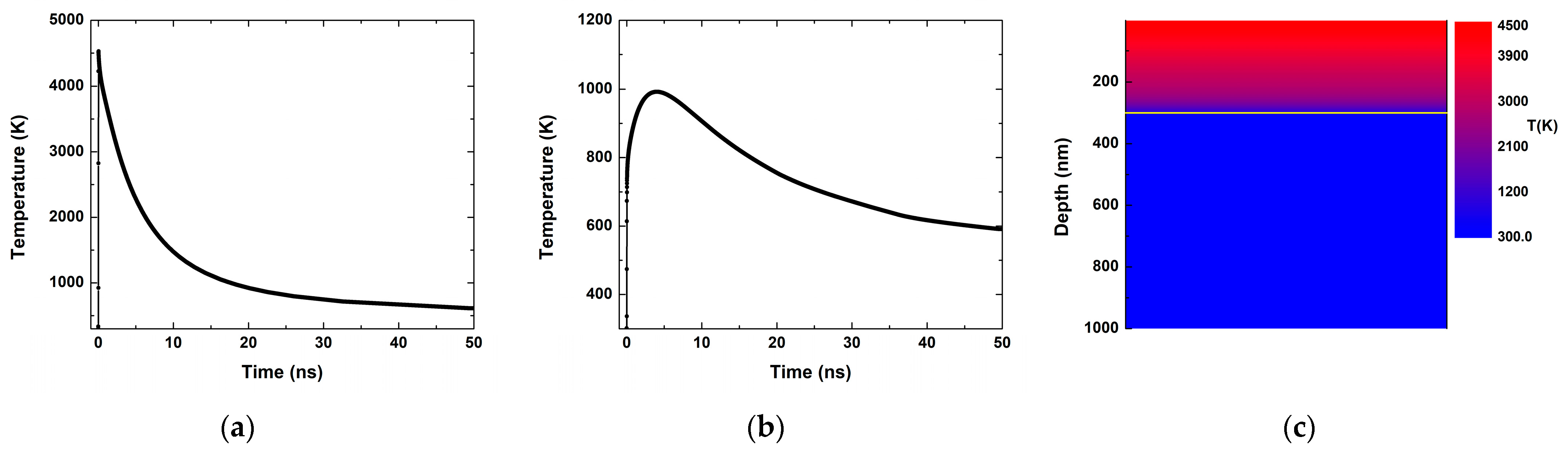
Figure 10 shows the estimated distribution of the temperature on the surface of the Fe film and its substrate when a 10 ps laser pulse is applied with fluence of 0.8 J/cm2. The time evolution of the Fe-film surface temperature is presented in Figure 10a. Instantly, the surface temperature rises to its maximum value of about 4500 K and exponentially decreases with time, reaching room temperature after 50 ns. The temperature of the Fe film’s substrate follows a similar behavior. A few ns suffice for the temperature of the substrate to reach its maximum value of about 1000 K (Figure 10b). More than 50 ns are needed for the substrate to cool to approximately half of the maximum value reached. Obviously, both the Fe film’s and the substrate’s surfaces cool down to room temperature before the next ps pulse arrives. The temperature distribution in the simulated system when the film surface temperature is maximum is shown in Figure 10c. The yellow line again delineates the substrate surface. It can be seen that the substrate temperature is lower than the melting point of the glass substrate when the film surface temperature is at its maximum.
4. Discussion
Regardless of the ablation regime (ns or ps), the material ablated from a bulk target in open air forms nanoparticles of various sizes, as previously reported [15,16,17,18,20,21]. The mechanism responsible for nanoparticles formation is condensation of the ablated species in the high-pressure (atmospheric) environment—the plasma plume formed due to the interaction of the laser pulse with the target material is compressed, which, in turn, favors the aggregation of the ablated species. In the case of ns ablation, the process taking place in open air results in nanoparticles/nanoparticle aggregates formation in the plasma plume due to condensation of the ablated material (atoms, ions, and small clusters) [15,16,17]. In the case of ps ablation, the ultrashort laser pulses directly produce nanoparticles through fragmentation and/or phase explosion, leading to material removal [19,20,21]. The use of ns laser pulses for formation of nanoparticle or structures composed of nanoparticles is a well-developed and widely applied technology [15,16,17,18]. A detailed look at the microstructure of nanoparticles deposited by ns and ps ablation reveals some differences, as seen in Figure 2. Separated nanoparticles are rarely observed by direct ablation with ps laser pulses. The ablation by ps laser pulses leads to the formation of nanoparticles with slightly smaller diameters than those obtained by ns laser pulses (Figure 2). This confirms our previously reported results [20]. Further, we compared the results obtained by the experimental configuration shown in Figure 1 at II stage with those obtained by classical on-axis PLD configuration. We thus found that, independently of the laser pulse duration, the experimental setup for ablation used in this paper does not affect the deposited samples’ crystalline structure and phase composition.
Ablation from thin film is a specific case of laser–matter interaction where the geometric parameters of the film could significantly influence the processes involved. The film thickness determines the amount of absorbed energy, while the substrate properties impact the temperature evolution and the ablation mechanism. The processing conditions should be carefully chosen to prevent ablation from the substrate that would change the composition of the ablated material. The temperature evolutions (shown in Figure 9 and Figure 10) indicate that at the used laser fluences the temperature in the film exceeds the evaporation one. Furthermore, at the moment when the film surface temperature is maximal, the substrate temperature is lower than the melting temperature of glass substrate. These conditions define that the film would be ejected without evaporation of material from the substrate. The time lag between reaching the maximal temperatures in the film surface and the substrate also shows that the film decomposition would have occurred before significant heating of the substrate surface. This allows us to conclude that material from the substrate is not expected to be ejected.
Thin metal films were deposited by classical ns-PLD (Figure 1, I stage) as a first step of the fabrication of nanostructures consisting of composite nanoparticles. It should be mentioned that such films could be prepared by other deposition methods. After that, these films were used as targets for laser ablation. It should be mentioned that the experimental setup for ablation (Figure 1, II stage) used in this study considerably decreases the droplet formation typical for classical PLD technology.
The targets used for ablation were either pure Fe or Au-enriched FeAu films (Figures S1 and S3). Since Fe easily and fully oxidizes in air, an iron-oxide phase is formed on the surface of the Fe thin-film target. The chemical state on the film surface indicates that the binding of oxygen to iron results in the formation of Fe2O3 (Figure S2) [34]. When the laser beam starts scanning the thin-film surface, the initial material for ablation will be a combination of Fe and Fe-oxide. Furthermore, the experiments were performed in air. In this light, it is not surprising that the structure of the deposited material independent of the ablation regime applied is some kind of iron oxide (Figure 3). The phase composition of the material ablated from bulk and thin-film targets is identical regardless of the ablation regime applied (Figure 2a,b and Figure 3a,b). This experimental result confirms the theoretical predictions discussed above. Considering the size of the nanoparticles formed during ablation, it seems that the nanoparticles ablated from the bulk target have a smaller size than those ablated from the thin-film target. Here, it should be pointed out that the ablation threshold for the bulk target is substantially higher than the ablation threshold for the same material in the thin-film form, which makes the direct comparison inappropriate. In order to keep the same laser energy applied on the target (bulk and thin-film target), the size of the laser spot on the bulk target was decreased to obtain the necessary laser fluence for ablation. However, the size of the laser spot on the target to a certain degree predetermines the size of the nanoparticles produced in air. The use of a smaller laser spot size leads to a smaller quantity of ablated material which subsequently condenses in smaller-sized nanoparticles. Bearing the above in mind, one should not be surprised that the mean diameter of the nanoparticles produced by the ablation of a bulk target in this work is smaller than the one produced by the ablation of a thin-film target (Figure 2a,b and Figure 3a,b).
The phase composition of the nanostructure produced by ns ablation of thin Fe film was identified as the magnetite phase of iron oxide (Figure 3a). This result corroborates those previous reports [18]. When the Fe film was ablated by ps laser pulses, the structure of the deposited sample was identified predominantly as a maghemite phase of iron oxide (Figure 3b). The maghemite phase is a polymorph of hematite but has a similar ferrimagnetic behavior to magnetite [35]. Comparing the structures produced by ablation of Fe film with ns and ps laser pulses, a difference in the phase composition was observed. In this sense, the ablation regime applied influences the phase composition of the deposited samples. Further, a difference was also observed in the morphology of the structures produced by ns ablation of Fe film (Figure 4a,b).
In the case of alloyed FeAu film, by changing the ratio of the Au and Fe slice forming a mosaic target initially, we can alter the ratio of Fe and Au in the alloyed FeAu film. Here, it should be mentioned that the ablation threshold for Fe and Au is different, which means that the ablation efficiency for the two metals will differ. Hence, although the mosaic target was formed by equal parts Au and Fe, the quantity of Au in the deposited film was higher due to the lower ablation threshold of Au and subsequently higher ablation efficiency of this metal (Figure S4, Table S1). However, the surface of the alloyed film was also covered by the iron oxide phase (Figure S5) [34,36,37,38].
One of the main advantages of ns pulsed laser deposition is the stoichiometric transfer of material from the target to the substrate. However, since the process was performed in open air, some deviations in sample phase composition could be observed [20]. In the case of ns ablation of Au-enriched FeAu alloy film, two different alloyed phases of Fe and Au could be clearly distinguished (Figure 6a). We assume that the energetically favorable phases according to the Fe–Au diagram were formed in the plasma plume. In such a manner, composite alloyed nanoparticles were formed by ns ablation of FeAu film, as a variation in their phase composition could be observed (Figure 6a). The formation of composite nanoparticles was also confirmed by the position of the surface plasmon resonance observed from such nanoparticles (Figure 8a). The theoretical prediction shows that pure Au nanoparticles with similar dimensions demonstrate more than one surface plasmon resonance and their position is at the wavelength of about 520 nm as well as shifted to longer wavelengths [33]. Moreover, our results obtained from samples deposited by ns ablation of pure Au film (see Figure S8) well confirm the above. While iron nanoparticles do not show a characteristic absorption in the visible range of the spectrum (Figure S8), the presence of Fe can influence the plasmon resonance of Au. Such a shift of the plasmon resonance of Au-containing Fe alloyed nanoparticles has been previously reported [39,40]. Amendola et al. suggested that the redshift is most probably related to the heterogeneous composition of the particles or particle aggregations [40]. In our case, we assumed that the redshift in the surface plasmon resonance of the ns-deposited samples is due to the presence of particles with different alloy composition as well as to their size and size distribution (Figure 6a, Figure 7a and Figure S8).
In the case of ps ablation of the alloyed FeAu film, a decomposition was achieved of the alloy followed by formation of Au and Fe-oxide nanoparticles in open air (Figure 5b). The presence of Au nanoparticles was also confirmed by XRD analysis (Figure 6b). Further, the interaction of ps laser pulses with the material in open air led to the formation of nanoparticles with bimodal distribution (Figure 3b and Figure 5b). The small-sized nanoparticles were identified as pure Au and Fe-oxide phases (Figure 5b). Furthermore, the larger particles have a core–shell structure, as the shell was found to have different Fe-oxide phases (Figure 5b). The optical properties of this structure demonstrate the presence of plasmon resonance shifted to the longer wavelengths (Figure 8b). The redshift in the resonance position of Au nanoparticles is probably because the Au nanoparticles exist in the Fe-oxide nanoparticle environment and their interaction shifts the resonance at longer wavelengths (see Figure S8).
It should be noted that based on the results obtained by the XRD analyses of the structures deposited by ns and ps ablation of alloyed FeAu film, it seems that the iron and/or iron compounds are missing (Figure 6a,b). However, the presence of Fe in the deposited structures was confirmed by the EDX analyses (Figure S6, Table S2 and Figure S7, Table S3). This means that a significant portion of iron oxide nanoparticles are amorphous (Figure 6a). Further, the XRD method does not recognize nanoparticles below 5 nm in size as crystalline, so they are registered as an amorphous halo in the XRD pattern (Figure 6b).
It could be summarized that structures consisting of composite alloyed nanoparticles could be produced by classical ns ablation of alloyed FeAu film in open air, and that varying the Fe: Au ratio in the film changes the composition of alloyed particles produced. The use of ps ablation of the same alloyed film in open air generally decomposes the existing alloy. This ultrashort laser–matter interaction allows the fabrication of structures comprising composite core–shell nanoparticles with some kind of Fe-oxide phase forming the shell. To the best of our knowledge, composite core–shell particles produced by physical methods such as laser ablation in air have not been previously reported. Further, different alloyed films consisting of iron with other noble metals (FePt and FePd) could be used for the fabrication of nanoparticle-composed structures, as the ablation regime applied acts in a similar way to the case of FeAu.
5. Conclusions
Nanostructures consisting of composite nanoparticles were fabricated by ns and ps ablation in open air from thin Fe and Au-enriched FeAu alloy films. It was found that ablation by ps laser pulses leads to formation of nanoparticles with slightly smaller diameters than those obtained by ns laser pulses. Different phase composition was observed when an Fe film was ablated with ns and ps laser pulses, indicating that the ablation regime applied influences the phase composition of the deposited samples. Structures consisting of composite alloyed nanoparticles could be produced by classical ns ablation of alloyed FeAu film in open air and varying the Fe: Au ratio in the film changes the composition of alloyed particles produced. The use of ps ablation of the same alloyed film in open air generally decomposes the existing alloy to Au and Fe metals and causes oxidation of iron to oxide phase. In the latter case, the fabricated nanoparticles have a clearly expressed bimodal size distribution as larger-sized particles demonstrate a core–shell type structure with an Fe-oxide phase as shell. To the best of our knowledge, composite core–shell particles produced by physical methods such as laser ablation in air have not been previously reported. The obtained structures, regardless of the ablation regime applied, demonstrate a plasmon resonance attributed to the presence of Au or Au-containing nanoparticles. A theoretical study of the temperature distribution on the film surface and the film’s substrate with time was carried out to clarify the potential for application of the presented technology. The calculations show that at certain experimental conditions, material from the substrate is not expected to be ejected.
Supplementary Materials
The following supporting information can be downloaded at: https://www.mdpi.com/article/10.3390/coatings14050527/s1, Figure S1: XRD pattern of the iron film; Figure S2: XPS spectra of the iron film; Figure S3: XRD pattern of the alloyed FeAu film; Figure S4: EDX analysis of the alloyed FeAu film; Table S1: The estimated quantity of Fe and Au elements in the alloyed FeAu film; Figure S5: XPS spectra of the alloyed FeAu film; Figure S6: EDX analysis of the structure deposited by ns ablation of the alloyed FeAu film; Table S2: The estimated Fe and Au quantity in the structure deposited by ns ablation; Figure S7: EDX analysis of the structure deposited by ps ablation of the alloyed FeAu film; Table S3: The estimated Fe and Au quantity in the structure deposited by ps ablation; Figure S8. Optical properties of the samples deposited from pure Fe and Au films by (a) ns and (b) ps ablation.
Author Contributions
Conceptualization, A.O.D. and P.A.; methodology, A.O.D. and N.N.N.; formal analysis, D.K., G.A. (Genoveva Atanasova), and G.A. (Georgi Avdeev); investigation, A.O.D.; data curation, D.K., G.A. (Genoveva Atanasova) and G.A. (Georgi Avdeev); writing—original draft preparation, A.O.D.; writing—review and editing, N.N.N.; visualization, D.K. and G.A. (Genoveva Atanasova); project administration, A.O.D. All authors have read and agreed to the published version of the manuscript.
Funding
The authors wish to thank the financial support of project KP-06-N37/20 “Formation and physical properties of composite nanostructures of metal oxides and noble metals” under the “Competition for Financial Support of Basic Research Projects—2019” Program of the Bulgarian National Science Fund.
Institutional Review Board Statement
Not applicable.
Informed Consent Statement
Not applicable.
Data Availability Statement
Data are contained within the article and Supplementary Materials.
Acknowledgments
We acknowledge the use of the research equipment supported by National Roadmap for Scientific Infrastructure, financially coordinated by the Ministry of Education and Science of the Republic Bulgaria under project D01-351 (ELI-ERIC BG). Research equipment of Distributed Research Infrastructure INFRAMAT, part of Bulgarian National Roadmap for Research Infrastructures, supported by Bulgarian Ministry of Education and Science was used in this investigation.
Conflicts of Interest
The authors declare no conflicts of interest.
References
- Jungwirth, T.; Marti, M.; Wadley, P.; Wunderlich, J. Antiferromagnetic spintronics. Nat. Nanotechnol. 2016, 11, 231–241. [Google Scholar] [CrossRef] [PubMed]
- Ali, A.; Zafar, H.; Zia, M.; ul Haq, I.; Phull, A.R.; Ali, J.S.; Hussain, A. Synthesis, characterization, applications, and challenges of iron oxide nanoparticles. Nanotechnol. Sci. Appl. 2016, 9, 49–67. [Google Scholar] [CrossRef] [PubMed]
- Meng, Y.Q.; Shi, Y.N.; Zhu, Y.P.; Liu, Y.Q.; Gu, L.W.; Liu, D.D.; Ma, A.; Xia, F.; Guo, Q.Y.; Xu, C.C.; et al. Recent trends in preparation and biomedical applications of iron oxide nanoparticles. J. Nanobiotechnol. 2024, 22, 24. [Google Scholar] [CrossRef]
- Ali, A.; Shah, T.; Ullah, R.; Zhou, P.; Guo, M.; Ovais, M.; Tan, Z.; Rui, Y. Review on Recent Progress in Magnetic Nanoparticles: Synthesis, Characterization, and Diverse Applications. Front. Chem. 2021, 9, 629054. [Google Scholar] [CrossRef]
- Revathy, R.; Sajini, T.; Augustine, C.; Joseph, N. Iron-based magnetic nanomaterials: Sustainable approaches of synthesis and applications. Results Eng. 2023, 18, 101114. [Google Scholar] [CrossRef]
- Chen, L.; Xie, J.; Wang, Z.; Zhao, Y.; Gou, J.; Wu, J. Amorphous Pt-decorated α-Fe2O3 sensor with superior triethylamine sensing performance prepared by a one-step impregnation method. J. Alloys Compd. 2024, 976, 173330. [Google Scholar] [CrossRef]
- Mikaeili Ghezeljeh, S.; Salehzadeh, A.; Ataei-e Jaliseh, S. Iron oxide nanoparticles coated with Glucose and conjugated with Safranal (Fe3O4@Glu-Safranal NPs) inducing apoptosis in liver cancer cell line (HepG2). BMC Chem. 2024, 18, 33. [Google Scholar] [CrossRef] [PubMed]
- Ling, D.; Hyeon, T. Chemical Design of Biocompatible Iron Oxide Nanoparticles for Medical Applications. Small 2012, 9, 1450–1466. [Google Scholar] [CrossRef]
- Nana, A.B.A.; Marimuthu, T.; Kondiah, P.P.D.; Choonara, Y.E.; Du Toit, L.C.; Pillay, V. Multifunctional magnetic nanowires: Design, fabrication, and future prospects as cancer therapeutics. Cancers 2019, 11, 1956. [Google Scholar] [CrossRef]
- Andrade, R.G.D.; Veloso, S.R.S.; Castanheira, E.M.S. Shape Anisotropic Iron Oxide-Based Magnetic Nanoparticles: Synthesis and Biomedical Applications. Int. J. Mol. Sci. 2020, 21, 2455. [Google Scholar] [CrossRef]
- Mondal, P.; Anweshan, A.; Purkait, M.K. Green synthesis and environmental application of iron-based nanomaterials and nanocomposite: A review. Chemosphere 2020, 259, 127509. [Google Scholar] [CrossRef] [PubMed]
- Eason, R. Pulsed Laser Deposition of Thin Films: Applications-Led Growth of Functional Materials; John Wiley & Sons, Inc.: New York, NY, USA, 2007; ISBN 9780470052129. [Google Scholar]
- Boutinguiza, M.; Comesaña, R.; Lusquiños, F.; Riveiro, A.; del Val, J.; Pou, J. Production of silver nanoparticles by laser ablation in open air. Appl. Surf. Sci. 2015, 336, 108–111. [Google Scholar] [CrossRef]
- Białous, A.; Gazda, M.; Grochowska, K.; Atanasov, P.; Dikovska, A.; Nedyalkov, N.; Reszczyńska, J.; Zaleska-Medowska, A.; Śliwiński, G. Nanoporous TiO2 electrode grown by laser ablation of titanium in air at atmospheric pressure and room temperature. Thin Solid Films 2016, 601, 41–44. [Google Scholar] [CrossRef]
- Nikov, R.G.; Dikovska, A.O.; Atanasova, G.B.; Avdeev, G.V.; Nedyalkov, N.N. Magnetic field-assisted formation of oriented nanowires produced by PLD in open air. Appl. Surf. Sci. 2018, 458, 273–280. [Google Scholar] [CrossRef]
- Nikov, R.G.; Dikovska, A.O.; Avdeev, G.V.; Amoruso, S.; Ausanio, G.; Nedyalkov, N.N. PLD fabrication of oriented nanowires in magnetic field. Appl. Surf. Sci. 2019, 471, 368–374. [Google Scholar] [CrossRef]
- Nikov, R.G.; Dikovska, A.O.; Avdeev, G.V.; Atanasova, G.B.; Nedyalkov, N.N. Composite magnetic and non-magnetic oxide nanostructures fabricated by a laser-based technique. Appl. Surf. Sci. 2021, 549, 49204. [Google Scholar] [CrossRef]
- Nikov, R.G.; Dikovska, A.O.; Avdeev, G.V.; Atanasova, G.B.; Karashanova, D.B.; Amoruso, S.; Ausanio, G.; Nedyalkov, N.N. Single-step fabrication of oriented composite nanowires by pulsed laser deposition in magnetic field. Mater. Today Commun. 2021, 26, 101717. [Google Scholar] [CrossRef]
- Nedyalkov, N.; Nakajima, Y.; Terakawa, M. Magnetic nanoparticle composed nanowires fabricated by ultrashort laser ablation in air. Appl. Phys. Lett. 2016, 108, 043107. [Google Scholar] [CrossRef]
- Dikovska, A.; Atanasova, G.; Nikov, R.; Avdeev, G.; Cherkezova-Zheleva, Z.; Paneva, D.; Nedyalkov, N. Formation of Oriented Nanowires from Mixed Metal Oxides. Materials 2023, 16, 6446. [Google Scholar] [CrossRef]
- Dikovska, A.; Atanasova, G.; Dilova, T.; Baeva, A.; Avdeev, G.; Atanasov, P.; Nedyalkov, N. Picosecond Pulsed Laser Deposition of Metals and Metal Oxides. Materials 2023, 16, 6364. [Google Scholar] [CrossRef]
- Kim, B.; Nam, H.K.; Watanabe, S.; Park, S.; Kim, Y.; Kim, Y.-J.; Fushinobu, K.; Kim, S.-W. Selective Laser Ablation of Metal Thin Films Using Ultrashort Pulses. Int. J. Precis. Eng. Manuf.-Green. Technol. 2021, 8, 771–782. [Google Scholar] [CrossRef]
- Hallum, G.E.; Kurschner, D.; Redka, D.; Niethammer, D.; Schulz, W.; Huber, H.P. Time-resolved ultrafast laser ablation dynamics of thin film indium tin oxide. Opt. Express 2021, 29, 30062. [Google Scholar] [CrossRef] [PubMed]
- Kim, B.; Nam, H.-K.; Kim, Y.-J.; Kim, S.-W. Lift-Off Ablation of Metal Thin Films for Micropatterning Using Ultrashort Laser Pulses. Metals 2021, 11, 1586. [Google Scholar] [CrossRef]
- Domke, M.; Nobile, L.; Rapp, S.; Eiselen, S.; Sotrop, J.; Huber, H.P.; Schmidt, M. Understanding thin film laser ablation: The role of the effective penetration depth and the film thickness. Phys. Procedia 2014, 56, 1007–1014. [Google Scholar] [CrossRef]
- Amendola, V.; Amans, D.; Ishikawa, Y.; Koshizaki, N.; Scirè, S.; Compagnini, G.; Reichenberger, S.; Barcikowski, S. Room-Temperature Laser Synthesis in Liquid of Oxide, Metal-Oxide Core-Shells, and Doped Oxide Nanoparticles. Chem. Eur. J. 2020, 26, 9206. [Google Scholar] [CrossRef] [PubMed]
- Amendola, V. Laser-Assisted Synthesis of Non-Equilibrium Nanoalloys. Chem. Phys. Chem. 2021, 22, 622–624. [Google Scholar] [CrossRef] [PubMed]
- Coviello, V.; Forrer, D.; Amendola, V. Recent Developments in Plasmonic Alloy Nanoparticles: Synthesis, Modelling, Properties and Applications. Chem. Phys. Chem. 2022, 23, e202200136. [Google Scholar] [CrossRef]
- Press, W.H.; Teukolsky, S.A.; Vetterling, W.T.; Flannery, B.P. Numerical Recipes in Fortran, 1st ed.; University Press: Cambridge, UK, 1992; ISBN 10: 0521383307. [Google Scholar]
- Lasemia, N.; Pachera, U.; Zhigilei, L.V.; Bomatí-Miguela, O.; Lahozd, R.; Kautek, W. Pulsed laser ablation and incubation of nickel, iron and tungsten in liquids and air. Appl. Surf. Sci. 2018, 433, 772–779. [Google Scholar] [CrossRef]
- Artyukov, I.A.; Zayarniy, D.A.; Ionin, A.A.; Kudryashov, S.I.; Makarov, S.V.; Saltuganov, P.N. Relaxation Phenomena in Electronic and Lattice Subsystems on Iron Surface during Its Ablation by Ultrashort Laser Pulses. JETP Lett. 2014, 99, 51–55. [Google Scholar] [CrossRef]
- Fernandez-Pañella, A.; Ogitsu, T.; Engelhorn, K.; Correa, A.A.; Barbrel, B.; Hamel, S.; Prendergast, D.G.; Pemmaraju, D.; Beckwith, M.A.; Bae, L.J.; et al. Reduction of electron-phonon coupling in warm dense iron. Phys. Rev. B 2020, 101, 184309. [Google Scholar] [CrossRef]
- Amendola, V.; Pilot, R.; Frasconi, M.; Maragò, O.M.; Iatì, M.A. Surface plasmon resonance in gold nanoparticles: A review. J. Phys. Condens. Matter 2017, 29, 203002. [Google Scholar] [CrossRef] [PubMed]
- Yamashita, T.; Hayes, P. Analysis of XPS spectra of Fe2+ and Fe3+ ions in oxide materials. Appl. Surf. Sci. 2008, 254, 2441–2449. [Google Scholar] [CrossRef]
- Shokrollahi, H. A review of the magnetic properties, synthesis methods and applications of maghemite. J. Magn. Magn. Mater. 2017, 426, 74–81. [Google Scholar] [CrossRef]
- Biesinger, M.C.; Payne, B.P.; Grosvenor, A.P.; Lau, L.W.M.; Gerson, A.R.; Smart, R.S. Resolving surface chemical states in XPS analysis of first row transition metals, oxides and hydroxides: Cr, Mn, Fe, Co and Ni. Appl. Surf. Sci. 2011, 257, 2717–2730. [Google Scholar] [CrossRef]
- Pannu, C.; Bala, M.; Khan, S.A.; Srivastava, S.K.; Kabiraj, D.; Avasthi, D.K. Synthesis and characterization of Au–Fe alloy nanoparticles embedded in a silica matrix by atom beam sputtering. RSC Adv. 2015, 5, 92080–92088. [Google Scholar] [CrossRef]
- Liu, M.; Zhou, W.; Wang, T.; Wang, D.; Liu, L.; Ye, J. High Performance Au-Cu Alloy for Enhanced Visible-light Water Splitting Driven by Coinage Metals. Chem. Commun. 2016, 52, 4694–4697. [Google Scholar] [CrossRef] [PubMed]
- Liu, H.L.; Wu, J.H.; Min, J.H.; Kim, Y.K. Synthesis of monosized magnetic-optical AuFe alloy nanoparticles. J. Appl. Phys. 2008, 103, 07D529. [Google Scholar] [CrossRef]
- Amendola, V.; Meneghetti, M.; Bakr, O.M.; Riello, P.; Polizzi, S.; Anjum, D.H.; Fiameni, S.; Arosio, P.; Orlando, T.; Fernandez, C.J.; et al. Coexistence of plasmonic and magnetic properties in Au89Fe11 nanoalloys. Nanoscale 2013, 5, 5611–5619. [Google Scholar] [CrossRef]
Figure 1.
Schematic view of the experimental setup.
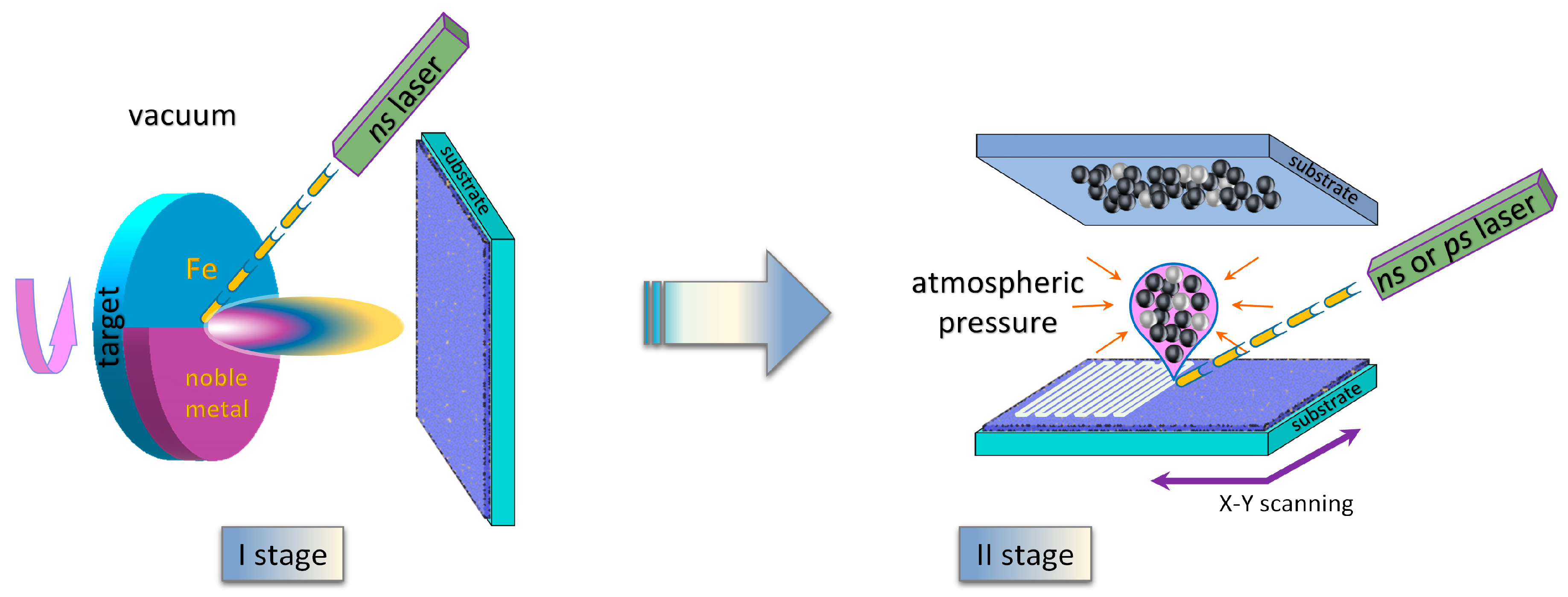
Figure 2.
TEM images, size distributions, and SAED patterns of the samples produced by (a) ns and (b) ps ablation of Fe bulk. In the respective SAED pattern, the maghemite phase of iron oxide is marked as “Mh”.
Figure 2.
TEM images, size distributions, and SAED patterns of the samples produced by (a) ns and (b) ps ablation of Fe bulk. In the respective SAED pattern, the maghemite phase of iron oxide is marked as “Mh”.

Figure 3.
TEM images, size distributions, and SAED patterns of the samples produced by (a) ns and (b) ps ablation of thin Fe film. In the respective SAED pattern, the maghemite phase of iron oxide is marked as “Mh”.
Figure 3.
TEM images, size distributions, and SAED patterns of the samples produced by (a) ns and (b) ps ablation of thin Fe film. In the respective SAED pattern, the maghemite phase of iron oxide is marked as “Mh”.
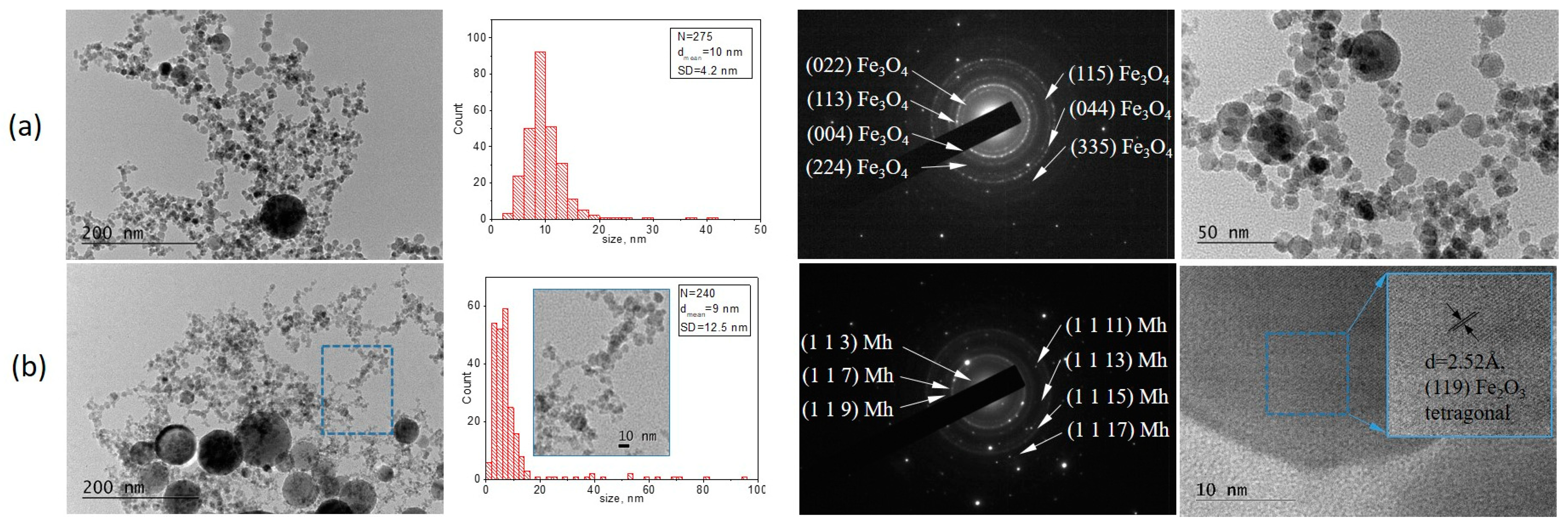
Figure 4.
SEM images of the samples produced by (a) ns and (b) ps ablation of thin Fe film.

Figure 5.
TEM images, size distributions, and SAED patterns of the samples produced by (a) ns and (b) ps ablation of alloyed FeAu film. In the respective SAED pattern, the maghemite phase of iron oxide is marked as “Mh”.
Figure 5.
TEM images, size distributions, and SAED patterns of the samples produced by (a) ns and (b) ps ablation of alloyed FeAu film. In the respective SAED pattern, the maghemite phase of iron oxide is marked as “Mh”.

Figure 6.
XRD of the samples produced by (a) ns and (b) ps ablation of alloyed FeAu film.
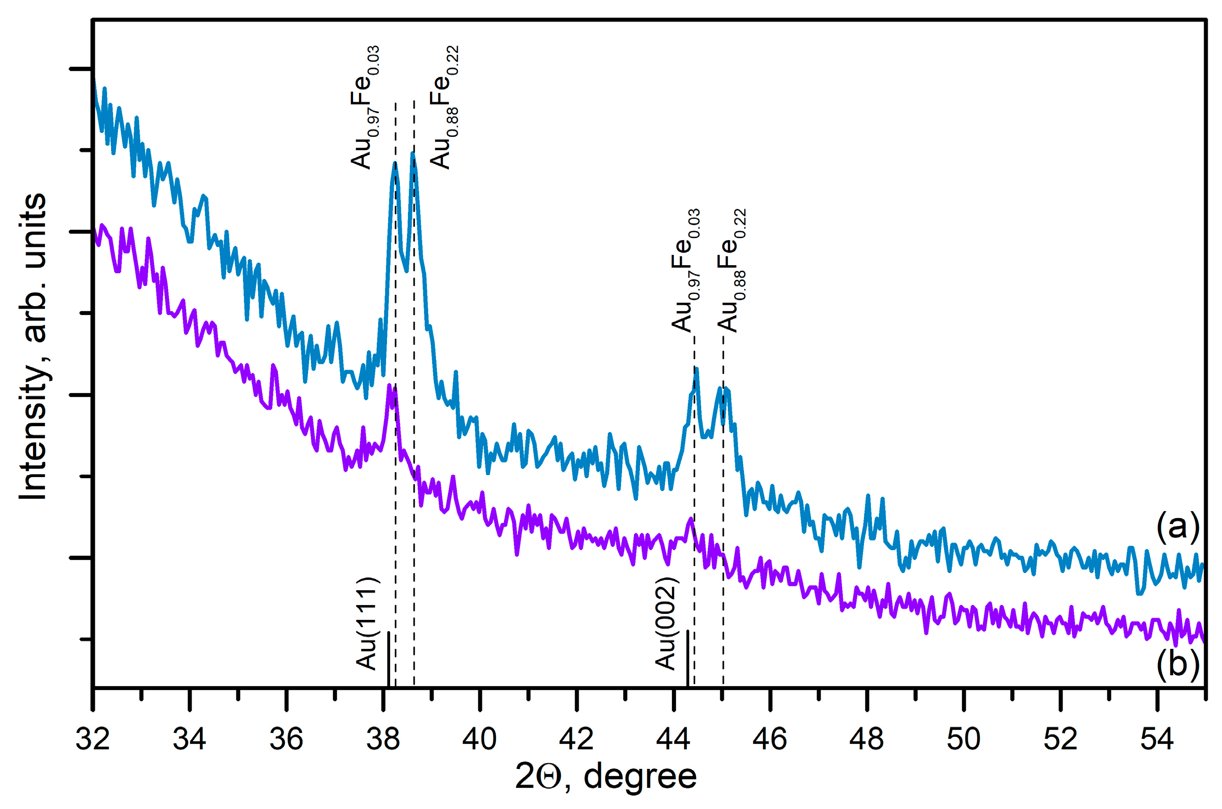
Figure 7.
SEM image of the samples produced by (a) ns and (b) ps ablation of thin FeAu film.
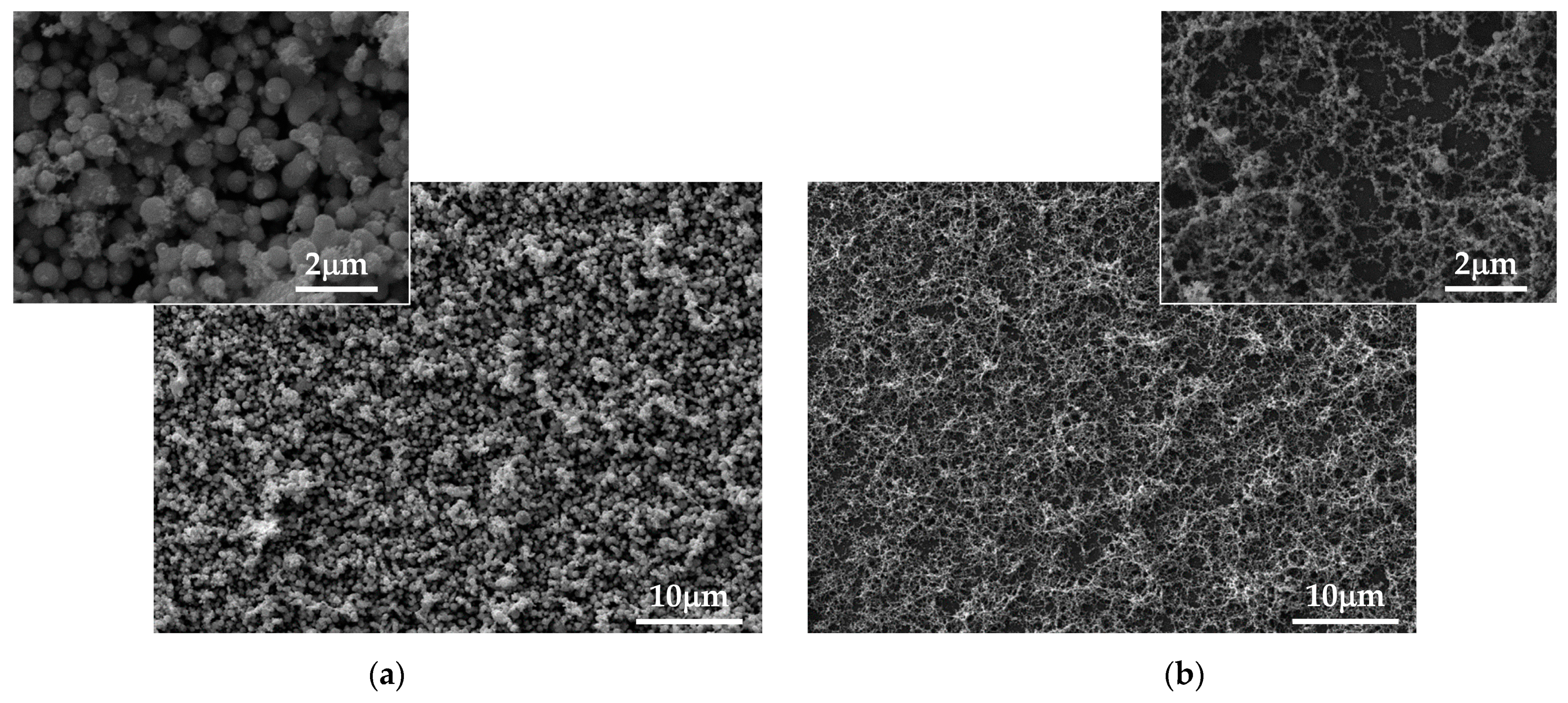
Figure 8.
Optical properties of the samples produced by (a) ns and (b) ps ablation of thin FeAu film.
Figure 8.
Optical properties of the samples produced by (a) ns and (b) ps ablation of thin FeAu film.
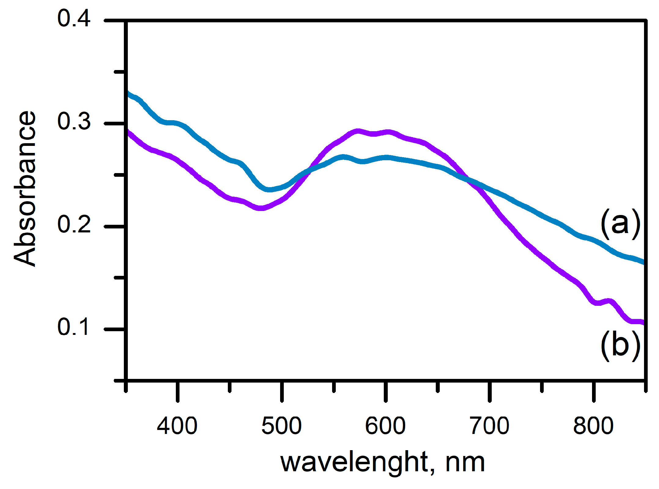
Figure 9.
Estimated temperature distribution on the surface of the Fe film and substrate when a 15 ns laser pulse with fluence of 1.5 J/cm2 is applied. (a) Time evolution of the Fe film surface temperature. (b) Time evolution of the glass substrate surface temperature. (c) Temperature distribution in the simulated system at the moment when the film surface temperature is maximal. The yellow line marks the substrate surface.
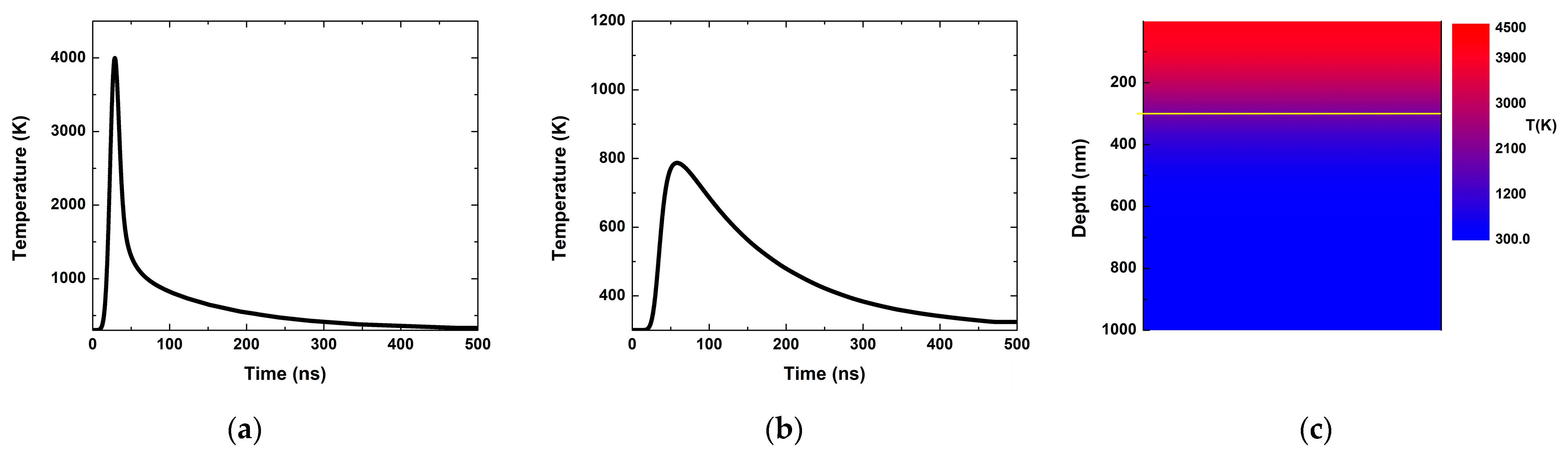
Figure 10.
Estimated temperature distribution on the surface of the Fe film and substrate when a 10 ps laser pulse with fluence of 0.8 J/cm2 is applied. (a) Time evolution of the Fe film surface temperature. (b) Time evolution of the glass substrate surface temperature. (c) Temperature distribution in the simulated system at the moment when the temperature of the film surface is maximal. The yellow line represents the substrate surface.
Disclaimer/Publisher’s Note: The statements, opinions and data contained in all publications are solely those of the individual author(s) and contributor(s) and not of MDPI and/or the editor(s). MDPI and/or the editor(s) disclaim responsibility for any injury to people or property resulting from any ideas, methods, instructions or products referred to in the content. |
© 2024 by the authors. Licensee MDPI, Basel, Switzerland. This article is an open access article distributed under the terms and conditions of the Creative Commons Attribution (CC BY) license (https://creativecommons.org/licenses/by/4.0/).
Share and Cite
MDPI and ACS Style
Dikovska, A.O.; Karashanova, D.; Atanasova, G.; Avdeev, G.; Atanasov, P.; Nedyalkov, N.N. Fabrication of Nanostructures Consisting of Composite Nanoparticles by Open-Air PLD. Coatings 2024, 14, 527. https://doi.org/10.3390/coatings14050527
AMA Style
Dikovska AO, Karashanova D, Atanasova G, Avdeev G, Atanasov P, Nedyalkov NN. Fabrication of Nanostructures Consisting of Composite Nanoparticles by Open-Air PLD. Coatings. 2024; 14(5):527. https://doi.org/10.3390/coatings14050527
Chicago/Turabian StyleDikovska, Anna Og, Daniela Karashanova, Genoveva Atanasova, Georgi Avdeev, Petar Atanasov, and Nikolay N. Nedyalkov. 2024. "Fabrication of Nanostructures Consisting of Composite Nanoparticles by Open-Air PLD" Coatings 14, no. 5: 527. https://doi.org/10.3390/coatings14050527
Note that from the first issue of 2016, this journal uses article numbers instead of page numbers. See further details here.