
A CFD Study of Particulate Deposition on Dimple-Type Flue Walls of Coal-Fired Power Plants
1
State Grid Xinjiang Company Limited Electric Power Research Institute, Urumqi 830047, China
2
State Grid Xinjiang Power Co., Ltd., Urumqi 830047, China
3
Laboratory of Energy Carbon Neutrality, School of Electrical Engineering, Xinjiang University, Urumqi 830047, China
4
Northwest Energy Carbon Neutral Engineering Research Centre, Ministry of Education, Xinjiang University, Urumqi 830047, China
5
Center of New Energy Research, School of Intelligence Science and Technology, Xinjiang University, Urumqi 830047, China
*
Authors to whom correspondence should be addressed.
Coatings 2024, 14(5), 526; https://doi.org/10.3390/coatings14050526
Submission received: 11 March 2024
/
Revised: 16 April 2024
/
Accepted: 18 April 2024
/
Published: 24 April 2024
(This article belongs to the Section Environmental Aspects in Colloid and Interface Science)
Abstract
:The study of particle deposition in bends is always a continuous challenge in various engineering and industrial applications. New types of channels with special microstructures on the surfaces can be effective in modifying the flow field structure as well as particle deposition in channels. In this study, a 90° circular bend with a convex dimple structure was used, and the flow field and the deposition of particles in the channel were analyzed; the Stokes numbers (St) used were 0.016, 0.355 and 1.397. The reliability of the model was ensured by mesh-independence validation as well as speed validation. In a 90° bend channel with convex dimples, the temperature distribution, particle deposition distribution, flow structure and secondary flow were examined. The effects of the number of convex dimples and St in the bend on the flow field structure and particle deposition characteristics were analyzed. The results show that the main factors affecting the deposition characteristics of particles in bends are St, gravitational deposition, thermophoretic force, turbulent vortex clusters and secondary flow distribution. The effect of St is more pronounced, with the deposition rate increasing as the St increases, and the deposition location of the particles is mainly clustered on the outside of the bend structure of the elbow.
1. Introduction
Energy is a key issue in the sustainable development of China, and the rapid progression of the national economy cannot be achieved without the sustainable use of energy. Chinese coal-rich, oil-poor and gas-poor energy resource characteristics determine the main energy status of coal in the short term and will not undergo fundamental changes. The share of raw coal production and consumption has consistently accounted for more than 50 percent of total energy production and consumption [1]. Specifically, it appears that coal consumption in the power sector accounts for about 57 percent of total coal consumption. Renewable energy sources such as wind power, photovoltaic, hydropower, nuclear power and biomass power are developing more rapidly, and their share in the power structure is gradually increasing. But in the short term, coal still holds an irreplaceable position in the power-generation industry [2]. Chinese steady economic development and increasing demand for electricity have stimulated the development of the power industry. Therefore, the power industry under coal-fired power generation as the main power generation structure has become the main industry of air pollutant emissions in China [3]. The air pollution situation in Xinjiang region is serious, among which the pollution situation in Wuchangshi area is severe. Since January 2023, a total of three heavy pollution weather processes have occurred in the “Wu-Chang-Shi” region, and two red alerts have been activated, making the situation of air pollution prevention and control extremely serious.
According to the statistics of the 2023 “Wu-Chang-Shi” Regional Atmospheric Environment Improvement Implementation Programme for People’s Livelihoods (Draft for Review), The “Wu-Chang-Shi” region emits 29,800 tonnes of sulfur dioxide (SO2), 76,600 tonnes of nitrogen oxides (NOx), 27,900 tonnes of particulate matter (PM) and 43,600 tonnes of volatile organic compounds (VOCs), with emissions from electric power production accounting for about 30 percent of the total pollutant emissions. Therefore, reducing pollutant emissions from coal-fired power plants is very important to the air pollution problem in Xinjiang.
In the boiler tail flue of a coal-fired power plant, particulate deposition in the bends becomes partly responsible for influencing the emission of pollutants. Due to the deposition of particulate matter, the operational efficiency of equipment was reduced and energy consumption increased. In bends, the effects of particulate deposition are not limited to reduced operating efficiency. For example, in pneumatic transport channellines, particle accumulation may obstruct fluid flow and lead to the risk of system failure or even explosion [4]. Particle deposition in heat exchangers can lower heat-transfer efficiency by creating a fouling layer that lowers the tube wall’s thermal conductivity, and the above situation can lead to an increase in energy consumption and an increase in operating costs [5]. Therefore, it is significant to investigate new channel structures to reduce particle deposition.
With the rapid development of Computational Fluid Dynamics (CFDs), researchers have had significant success in studying particle deposition in channel flows, including experimental studies and numerical analyses. Sippola and Nazaroff [6] experimentally measured the deposition efficiency of particles in bends and straight tubes, and the measurements revealed that particles were deposited more at the connections and bends. Sun et al. [7] conducted an experimental analysis to determine how the bending material, Reynolds number (Re) and particle concentration affected the deposition of particles in 90° square bends.
After an extensive literature review, it was found that there are many factors affecting particle deposition. Due to the complexity of particle flow in channels, CFD simulation can more easily obtain visualization results of the flow field compared to experiments. Therefore, numerical simulations are increasingly being used to explore the flow, heat transfer, and particle deposition of fluids in flow fields. Hong et al. [8] investigated particle deposition in a large-scale irregular surface with a channel roughness of 0.5 mm and compared it with particle deposition in a smooth channel. The results show that roughness significantly enhances the deposition of small particles, but the enhancement decreases with increasing particle diameter. Tu et al. [9] used numerical simulations to study the deposition patterns in aerosol microchannels under turbulent conditions. It was found that the main mechanism of aerosol deposition in microchannels is turbulent diffusion. Farahani et al. [10] used the Eulerian–Lagrangian two-way coupling method to simulate the gas flow and the flight behavior of particles during aerosol deposition. Hong et al. [11] carried out numerical simulations of gas-particle flows using the Reynolds Stress Model (RSM) and the Discrete Phase Model (DPM) to investigate the deposition characteristics of particles in rib-roughening channels. The windward side was found to be the primary deposition region and the cavities between the rough elements were found to be the secondary deposition region. Han et al. [12] investigated the effect of inlet velocity and particle diameter on the deposition efficiency on each wall of a rectangular channel. The results show that the efficiency of particle deposition at different locations in the channel can be varied by changing the particle diameter and flow rate. Particle infiltration in bends under laminar and turbulent flow conditions was examined by Cong et al. [13] They developed a new empirical function based on the Dean number and Stokes number (St) to predict the particle penetration efficiency. The deposition of particles in a heat-transfer channel with a concave dimple shape was investigated by Han et al. [14]. Concave dimples were discovered to have an impact on the flow field of the channel, increase heat exchange inside the channel, change the path of particles within the channel and encourage the deposition of microscopic particles. The impact of ribbed channel inclination angle on particle deposition characteristics was examined by Lu et al. [15] The findings indicate that the deposition effectiveness of tiny particles is only a little impacted by the inclination angle, but has a large effect on the deposition efficiency of large particles. Lu et al. [16] used the RSM model and the DPM model to simulate particle deposition in a 3D corrugated rough-walled channel. The results show that the use of corrugated wall surfaces significantly improves the deposition efficiency for particle diameters smaller than 20 μm. Han et al. [17] investigated particle deposition in a heat-exchange channel with a combination of concave and convex dimple shapes. It was found that the presence of convex dimples influenced the flow field within the channel, acting as a diversion for the concave dimples behind them, and that the presence of the concave dimples promoted particulate deposition at the dimples. Lu et al. [18] investigated the turbulence structure and particle deposition in a heat exchange channel with convex dimples. The presence of convex dimples was found to have some effect on the distribution of deposition locations of particles, but little effect on the rate of deposition of large particles.
Literature research revealed that there is a concerted effort to study the deposition of particles in channel flow. However, up to now, there have been limited studies on reducing deposition efficiency by changing the geometry. Arsalanloo and Abbasalizadeh [19] studied the effect of the use of inserts on the deposition efficiency in 90° circular bends. Erraghroughi et al. [20] investigated particle deposition in a curved turbulent channel with ribs, and it was found that after inserting the ribs, the particle deposition could be reduced. It has also been found that corrosion in bends can be effectively mitigated by inserting ribs, grooves, etc. Therefore, in this study, the heat-transfer characteristics and particle deposition characteristics inside a 90° circular bend with convex dimples were investigated based on previous studies. The analysis focused on the deposition of particles in 90° circular bends with convex dimples with particle diameters of 1 μm, 5 μm and 10 μm. The boundary condition of the channel walls and the walls at the convex dimples were set as the “Trap”. This followed the experimental conditions of Pui et al. [21] and the analog simulation results of other scholars [21,22,23]. The particles bouncing off the wall were not considered. Better results were obtained. In addition, the effect of different numbers of convex dimples on the rate of particle deposition in a 90° bend was discussed.
2. Materials and Methods
2.1. Continuous Phase
In this study, the Eulerian method is used to solve the continuous phase of turbulence. The fluid is considered incompressible and stable. The following equations can be used to solve the governing equations for momentum and continuity using the finite volume approach:
where g, ρ and v are the gravitational acceleration, air density and kinetic viscosity, respectively; is the time-averaged velocity of the air (m/s); Sij is the average strain rate tensor (s−1).
The different terms in Equation (2) correspond to the volumetric force, the pressure gradient force and the total stress tensor, which include the vicious and Reynolds stress tensor, respectively.
To model the Reynolds stress term, Renormalized Groupe (RNG) k-ε correctness has been proven by Yakhot et al. [24] In comparison to experimental data, Kim et al. [25] showed that the model produced good velocity streamlines and secondary flow distributions in the bends. According to Lidino et al. [22], the model offers a reliable means of validating particle deposition in bends. Compared to the Reynolds Stress Model (RSM), the RNG is easy to handle flows involving strong streamlines and separations and has fewer computational resources. The turbulent kinetic energy k transport equation and the turbulent dissipation rate ε transport equation for the RNG model are given by the following equations:
where Gk, μeff, μt and S are the turbulent kinetic energy from mean velocity gradient, effective kinetic viscosity, turbulent viscosity and modulus of the mean strain rate tensor produced by the mean velocity gradient, respectively; where Cμ, ζ0, β and C1ε are 0.0845, 4.38, 0.012 and 1.42, respectively.
The transport equations of the RNG model are used in the completely turbulent region. At the same time, the equations for the momentum and the kinetic energy of the turbulent flow continue to apply in the region affected by the viscosity. However, the turbulent viscosity and turbulent dissipation rate were calculated using the following equations:
where , , .
The governing equations of the turbulent wind field are solved using the Finite Volume Method (FVM). The calculations are performed using a pressure-based solver, the SIMPLE algorithm for pressure-velocity coupling, the PRESTO format for the discretized pressure equations and the second-order upwind scheme to discretize the convective and discrete terms.
2.2. Discrete Phase Model
By solving the equations of motion for the particles, the Lagrangian approach is utilized to forecast the trajectories of the particles in the air-flow field. Assuming that the particles have no effect on the continuous phase and ignore the interactions between the particles, the DPM one-way coupled discrete model is used. The force balance integral on the particle yields the particle trajectory:
where xp,i, up,i, ρp and dp are the position vector of the particle, the velocity vector of the particle, the particle density and the particle diameter, respectively. The right-hand side of Equation (15) is represented as the trailing force, gravity and buoyancy and additional force. Yin et al. [26] investigated the deposition of nanoparticles subjected to thermophoretic and Brownian forces inside a 90° square bend. The results of the study show that as the particle diameter decreases and the air temperature decreases, the Brownian forces become more pronounced and the particles become more uniformly distributed. The thermophoretic force dominates the deposition of larger particles, which increases with the temperature gradient. The effect of gravity on the deposition process becomes more important when the particle diameter is larger than 50 nm.
Among the additional forces are Brownian force FB, Saffman lift FS and thermophoretic force FT. [14,15,16,17,18]. These forces have been confirmed to be crucial for the deposition characteristics [27,28]:
where Cd is the drag coefficient.
The particles used in the study are spherical and Cd can be calculated from Equation (17). The values of a1, a2 and a3 in Equation (17) depend on the magnitude of the relative Reynolds number (Rer), which is calculated as shown below:
Brownian forces are generated due to random diffusion of particles, where the Brownian force FB is calculated with the expression:
where S0 is the spectral intensity of a Gaussian white noise random process.
The formula for the Saffman lift is:
The thermophoretic force is calculated as:
where DT,P is the thermophoretic coefficient.
2.3. Stochastic Turbulent Model
The particle phase was modeled using a Discrete Random Walk Model (DRW). It takes into account the effect of turbulence fluctuations on particle trajectories, and allows turbulent diffusion of particles associated with transient airflow fluctuations. The instantaneous airflow fluctuation ui is a combination of the average and fluctuating airflow velocities:
where ξ is a random number with a normal distribution, and is the root-mean-square fluctuation component in the i-th direction.
Vortex has time-scale properties τe:
where Tl is the Lagrangian integration time.
2.4. Particle Deposition Efficiency
The ratio of the mass of particles captured by the wall to the total mass of particles is the particle deposition efficiency. Since the injected particles have the same particle diameter and density, the mass can also be replaced by the number of particles.
The ratio of the system response time τs to the particle relaxation time τD is known as Stokes number (St):
where U0, D and CC are the mean flow rate, channel diameter and Cunningham correction factor, respectively:
where λ is the average free range of air.
3. Case Description
The basic geometric configuration of the bends studied in this paper is a 90° bend with convex dimples in the circular cross-section. The diameter of this channel is D = 8.51 mm and Reynolds number Re = 10,000. To prevent backflow at the outlet, the horizontal and vertical straight channels are long enough.
Case 1: A single convex dimple structure was set up in the center of the bend with a convex dimple depth of 0.89 mm, as shown in Figure 1a. Case 2: Add a convex dimple on each side of the first set of convex dimples. In total, there are three convex dimples, as shown in Figure 1b. To ensure that the particles are well mixed with air before entering the curved section, the incidence surface is located at twice the diameter of the inlet. Monodisperse was used for particle distribution in this study [14,15,29]. It provides a better understanding of the deposition of each particle individually. The particle diameters in this study were 1 μm, 5 μm and 10 μm. The incidence velocity of the particles is the same as the airflow velocity at the inlet. The inlet boundary condition is the velocity inlet and the outlet boundary condition is the pressure outlet. No-slip conditions were applied to both the channel walls and the walls at the convex dimples. The boundary condition of the channel walls and the walls at the convex dimples were set as the “Trap”. The wall temperature at both the channel wall and the convex dimple is 300 K. At the inlet, the hot air temperature is 425 K.
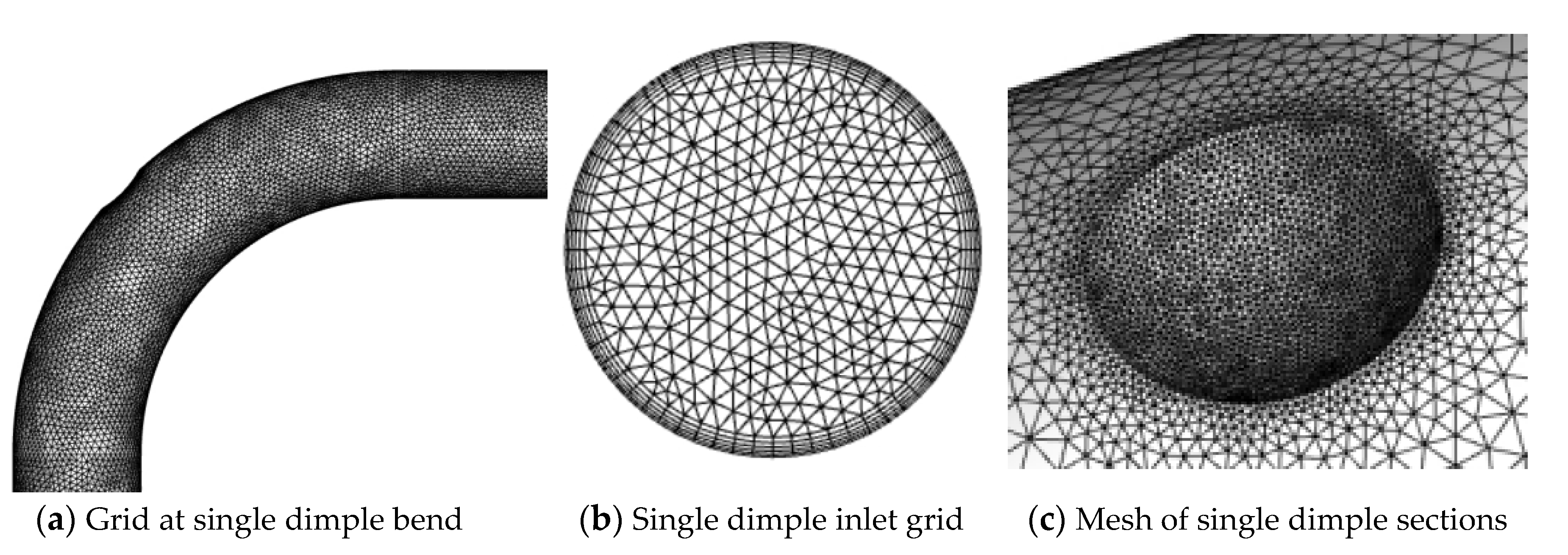
In this study, Ansys Fluent 2021R2 is used for simulation calculations. Meshing is used for grid division. Figure 2 shows a schematic diagram of the grid of bends with convex dimples. The overall grid cell size was 0.4 mm, with local encryption at the boundary layer with a cell size of 0.08 mm and a growth rate of 1.2. Grid-independent validation was carried out using five different grid number models, the grid numbers used for validation ranged from 120,098 to 1,214,617 and the results are shown in Figure 3. The particle deposition rate stabilizes when the number of grids exceeds 887,160. Considering the computational cost, the 887,160 grid number model was chosen for the calculation.
4. Results
4.1. Numerical Validation
Verification of single-phase turbulent flow in a 90° bend was carried out using the experiments of Sudo et al. [30] Comparison with experimental data from Sudo et al. and LES simulation results by Yan et al. [4] at two deflection angles, 0°, and 90°, with an air inlet velocity U0 and normalized mean flow velocity Us. The results of this study coincided with this, as shown in Figure 4. The inner area of the curve exhibits some variations at the outlet of bend (90°). The inverse pressure gradient close to the inner wall of the bend is what causes the observable discrepancy. This is the same as previous findings [4,30].
Figure 5 illustrates the numerical validation results of the deposition efficiency for 90° bends under different St. The present model was used to compare with the experimental data of Pui et al. [21] and the simulation results of Zhang et al. [31] and Guo et al. [32]. It can be found that the results are well-fitted and, in combination with Figure 4 and Figure 5, it can be shown that the numerical model of this study is reliable.
4.2. Analysis of Turbulent Flow Field
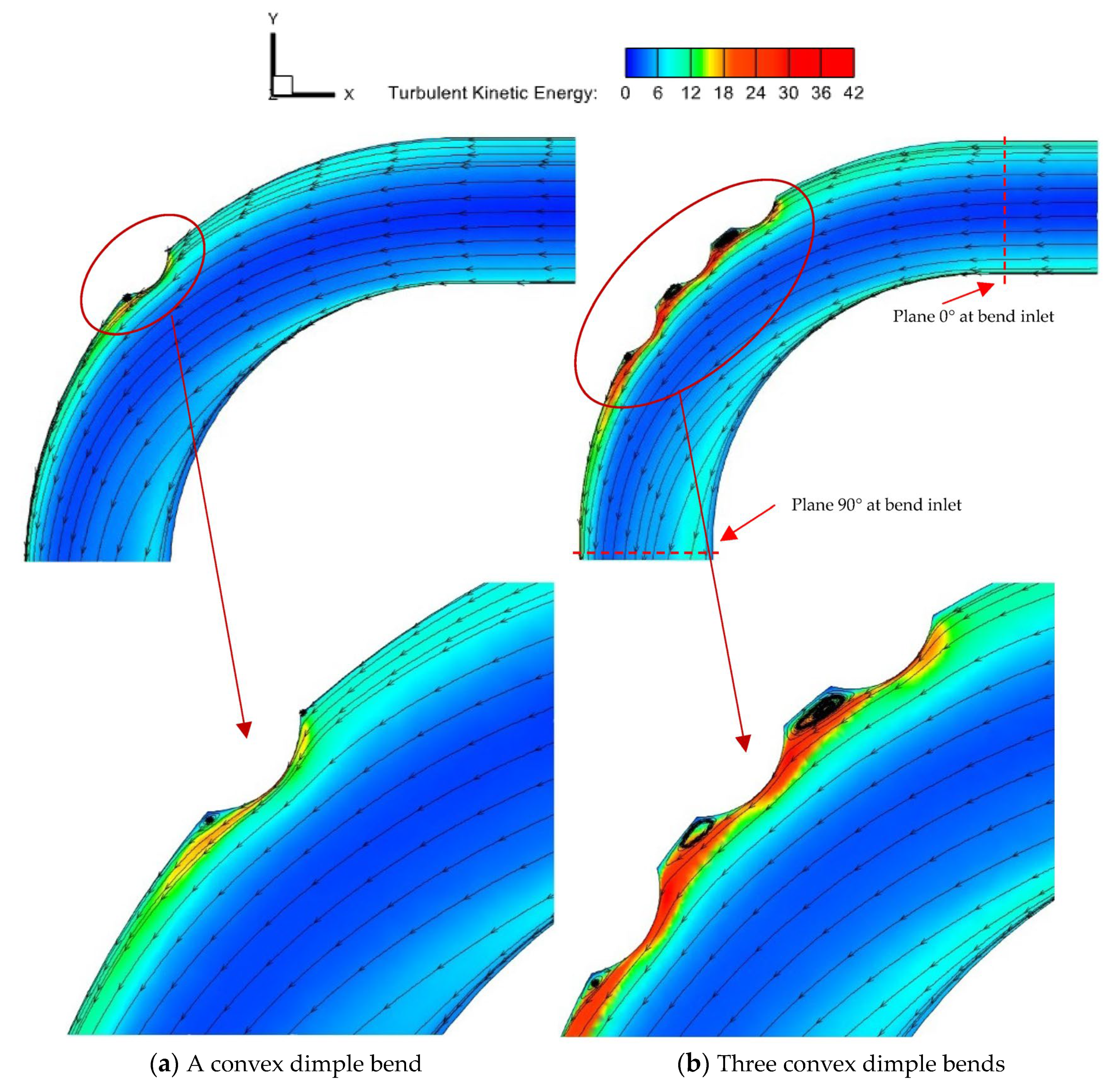
Figure 6a,b illustrates the airflow velocity field along the XY plane of the Z = 0 section for a single convex dimple and three convex dimples, respectively. Figure 6c,d shows the overall airflow velocity field for a single convex dimple and three convex dimples, respectively. The inlet velocity is 21.027 m/s and the direction is horizontally to the left. The temperatures of the cold wall surface and the hot air inlet are 300 K and 425 K, respectively. In the bend, the curvature generates centrifugal force. Upon entering the bend, the faster flowing fluid moves towards the inside of the bend, the core flow moves towards the outside of the bend, and the slower flowing flow moves towards the inside. As a result, a secondary flow is generated in the plane perpendicular to the average flow. Figure 7 shows the Turbulent Kinetic Energy (TKE) contours of the 90° bend with a convex dimple structure and a local enlargement of the TKE at the convex dimple. The inclusion of two convex dimple structures on either side of the convex dimple resulted in a large increase in TKE values near the region. Unlike the smoothness of the bend wall, the inner wall at the bend convex dimple amplifies the region of high TKE values. In addition, significant areas of high TKE values were observed on the windward and leeward sides of the single convex dimple, and the middle part of the three convex dimples being the most pronounced. This is due to the presence of induced vortices in the region, which can be seen between the two dimples, which have a distinct vortex mass present. Furthermore, as Figure 8 illustrates, the temperature field and velocity vector maps in the YZ plane were obtained. Planes a and b are selected from the two planes at 0° and 90° of the inlet of the bend (as shown in Figure 7). There is a significant temperature gradient between the center of the channel and the wall, which causes a thermophoretic force to be generated in the channel from the hot to the cold temperature region. Differences in temperature gradients will result in different distributions of thermophoretic forces within the channel. The particles will migrate from the high-temperature center to the low-temperature wall region due to thermophoretic forces acting on them, which will facilitate contact between the particles in this region and the wall. Secondary flow is present in the vertical direction in the second half of the bend and is evident near the right wall of the channel. The secondary flow will affect the flow of small particles in the channel, which is important for the deposition of particles on the wall. Figure 8 shows that the secondary flow structure in the bend model is not significantly impacted by variations in the number of convex dimples.
4.3. Particle Deposition Rate Analysis
4.3.1. Effect of Stokes Number on Particle Deposition
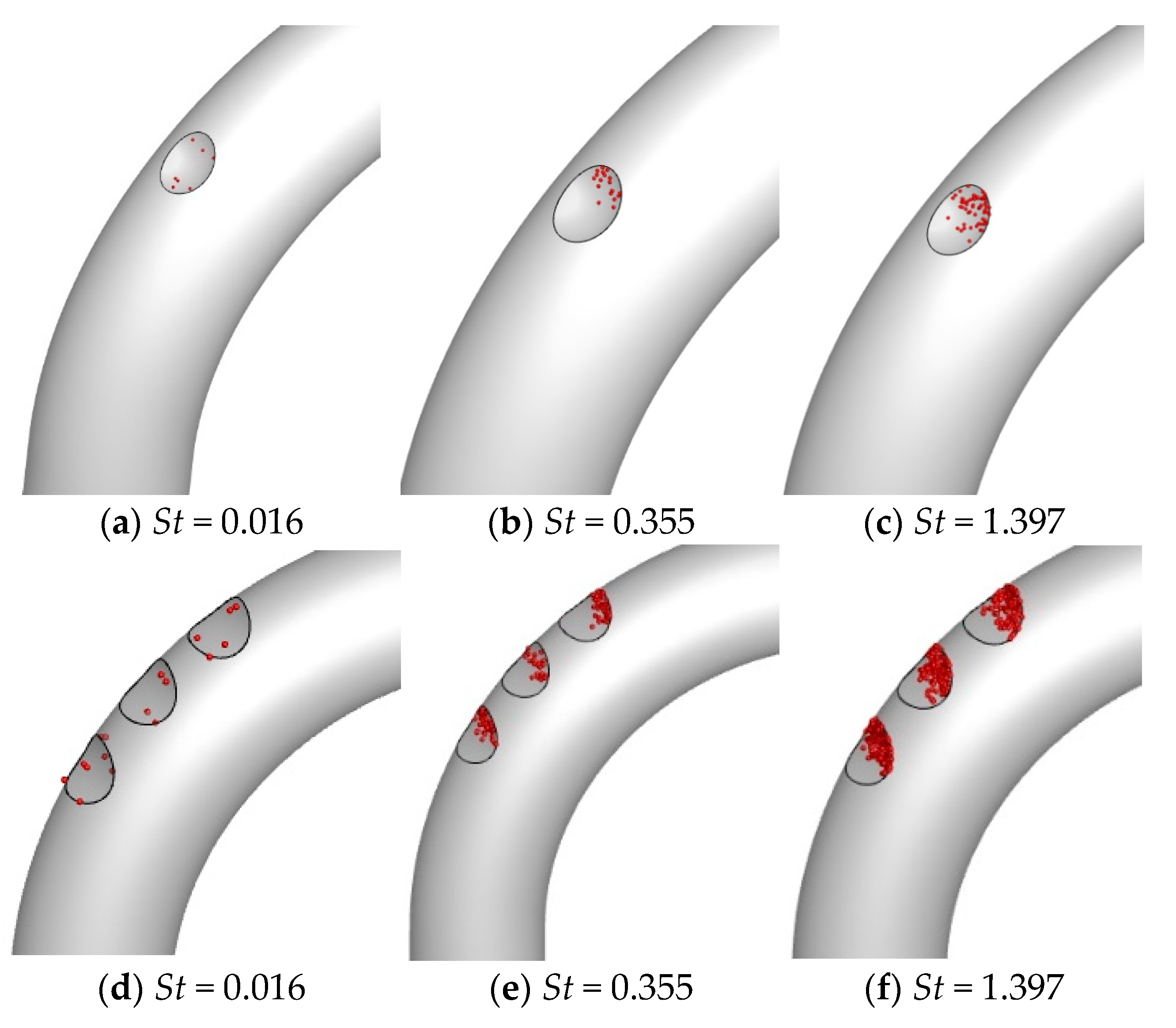
Figure 9 shows the deposition morphology of particles with different St at the convex dimple. Figure 9a,d demonstrates the deposition location of particles with St = 0.016 in the convex dimple. At this time, the particle size is smaller and more likely to move with the airflow disturbance. The presence of vortex clusters in the vicinity of the convex dimple affects the deposition of smaller particle sizes and promotes the deposition of particles in the convex dimple cavity. Figure 9b,e demonstrates the deposition location of particles with St = 0.355 in the convex dimple. A strong TKE zone exists near the convex dimple and the TKE values are greater on the windward side than on the leeward side, allowing particle deposition to occur mainly on the windward side of the convex dimple. As shown in Figure 9c,f, when the St increases to 1.397, more particles are deposited in the convex dimple section, especially at the windward side of the convex dimple.
By observation, it was found to be simpler for smaller particles (St = 0.016) to follow the airflow and leave the convex dimple. However, it is more difficult for larger particles (St = 0.355) to change course or be carried away by the airflow. Figure 10 illustrates the deposition locations of particles with different St on the wall and at the convex dimples. With the increase in St, more particles are deposited in the curved part. This is because as the St of the particles increases, the particle size increases and the inertia of the particles increases. The particles no longer flow closely with the airflow and they are less sensitive to turbulent fluctuations. Particles within a core area of the airflow are forced outward and toward the bend exterior by centrifugal force, where they are eventually deposited. When the St increases to St= 1.397, inertia and centrifugal force result in almost complete deposition of particles in the outer curved portion of the bend.
As shown in Figure 10, there is less particle deposition on the leeward side of the convex dimple and between the two convex dimples. This is because vortex clusters between the leeward side and the two convex dimples act on the particles and blow them apart. When the St is small, the particle size of the particles is smaller, the particle inertia is small, the influence of airflow is large, and the particle deposition position is uniform. The results of the study found that different St has a greater effect on the deposition rate. When the St is small St = 0.016, the particles can escape better with the airflow and deposit less at the convex dimple. When the St is large St = 1.397, most of the particles are deposited on the wall surface. The deposition was mainly at the bends of the elbows and deposition at the convex dimples was mainly on the windward side of the convex dimples.
4.3.2. Effect of Different Convex Dimple Numbers on Particle Deposition
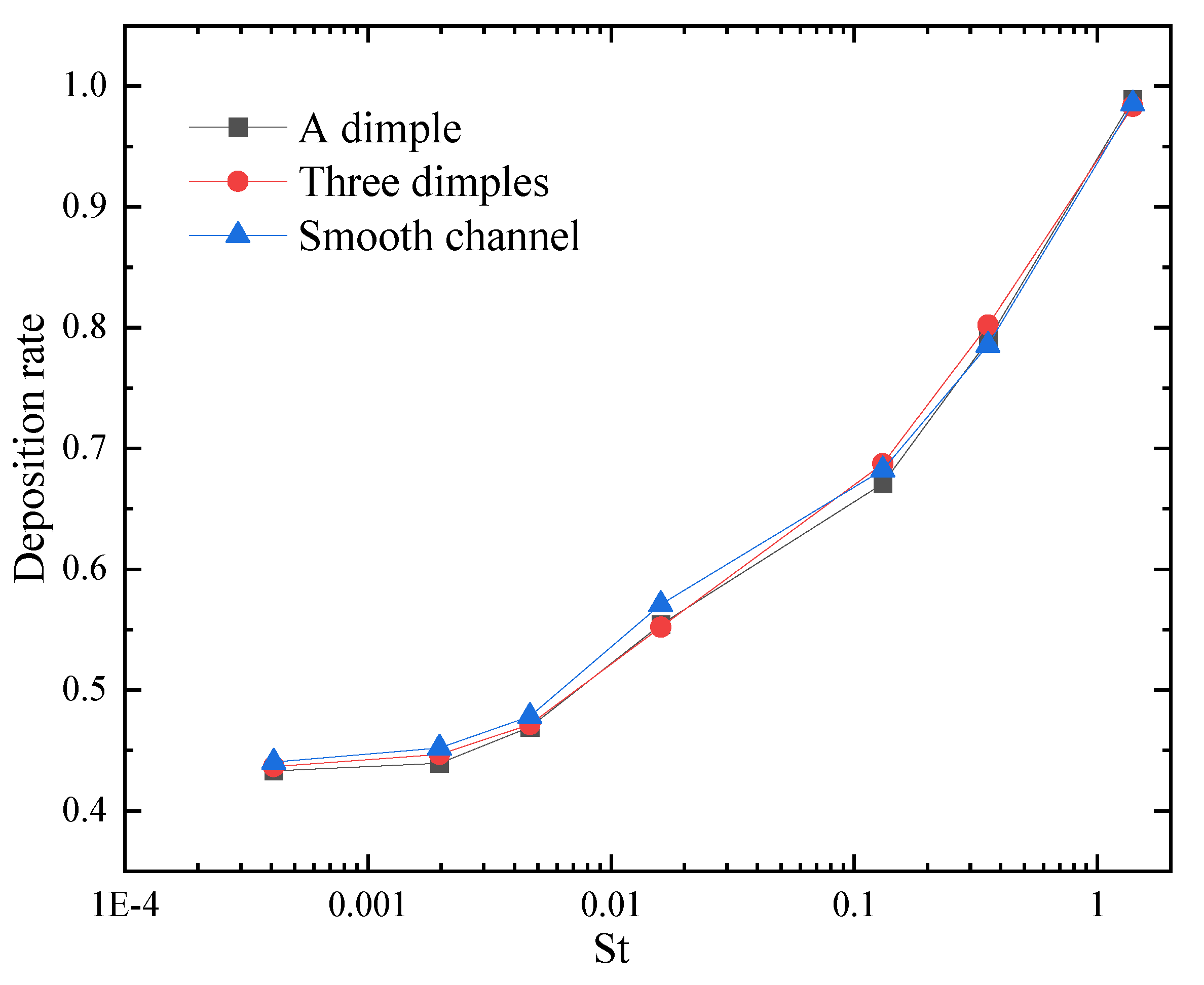
Figure 11 shows that the convex dimple structure reduces the deposition rate of particulate matter in a 90° bend. Deposition is effective for small particles and limited for large particles because of their greater gravity and inertia. The primary force influencing particle deposition is gravity and turbulent vortices and secondary flows in the flow field have less of an impact on larger particles. Therefore, the deposition rate is higher for larger particle diameters. The reduced particle deposition efficiency of a bend with a convex dimple structure compared to a bend without a convex dimple structure is due to the interception of small particles on the windward side of the convex dimple. Meanwhile, particles with greater inertia are intercepted in the deepest region of the convex dimple and on the windward side. A reduced bend deposition surface with a convex dimple structure protects the bend from direct particle impact and improves the corrosion resistance of the bend. As the number of convex dimples increases, there is no significant reduction in the efficiency of particle deposition.
5. Conclusions
The CFD method was used to numerically simulate particle deposition in the 90° bend. For the fluid phase, the RNG k-ε model was employed, while the particle phase was represented by the Discrete Particle Model (DPM). The incorporation of a convex dimple structure in the bend effectively improves the flow structure as well as particle deposition in the flow field. The airflow field, particle deposition characteristics and deposition efficiency are examined and discussed and the results are as follows:
- (1)
- The presence of convex dimple structures can have an impact on the flow field in the bend channel as well as on the particle deposition characteristics. In this case, for particles with small St, it will encourage their deposition inside the convex dimple cavity. And for particles with larger St, this leads to more particles being deposited on the windward side of the convex dimple.
- (2)
- As the number of convex dimples increases, the TKE value near the convex dimple will increase significantly. At the same time, a higher temperature gradient will exist near the channel wall. These reasons will promote particle deposition. The presence of vortex clusters between the two convex dimples allows fewer particles to be deposited there. An increase in the number of convex dimples does not significantly reduce the rate of particle deposition.
- (3)
- Particle deposition in the bend is influenced by a different St, and as the St increases, the rate of particle deposition increases. As the St increases, the particle diameter increases, and the inertial force of the particles increases. The concentration of particles deposited in the curved portion of the bend is more pronounced.
- (4)
- A special convex dimple-type structure is added to the bend portion of the elbow, which effectively reduces the deposition of some particles. When applied in the tail flue of a coal-fired power plant, it can improve the operating efficiency of the equipment and reduce energy consumption. In future studies, User-Defined Functions (UDFs) will be used to bring the deposition of particles closer to reality. In addition, inter-particle collisions are important for regions where particles are highly aggregated.
Author Contributions
Conceptualization, D.H. and X.C.; methodology, D.H. and M.L.; software, Z.H.; validation, D.H., X.C. and H.L.; formal analysis, H.L.; investigation, D.H.; data curation, M.L.; writing—original draft preparation, D.H., X.C. and H.L.; writing—review and editing, D.H. and Z.H.; visualization, X.C. and Z.H.; supervision, H.L.; project administration, D.H.; funding acquisition, D.H. All authors have read and agreed to the published version of the manuscript.
Funding
The funding is provided by the State Grid Company Limited Electric Power Research Institute Science and Technology Project (SGXJJJOOKJJS2310038).
Institutional Review Board Statement
Not applicable.
Informed Consent Statement
Not applicable.
Data Availability Statement
Data are contained within the article.
Conflicts of Interest
Author Dong Hua and Mengke Liao were employed by the company State Grid Xinjiang Company Limited Electric Power Research Institute. Author Xiqiang Chang was employed by the company State Grid Xinjiang Power Co., Ltd. The remaining authors declare that the research was conducted in the absence of any commercial or financial relationships that could be construed as a potential conflict of interest. The authors declare that this study received funding from State Grid Company Limited. The funder was not involved in the study design, collection, analysis, interpretation of data, the writing of this article or the decision to submit it for publication.
Nomenclature
| Cunningham correction factor | |
| drag coefficient | |
| diameter of dust particle (μm) | |
| channel diameter (m) | |
| thermophoretic coefficient | |
| Brownian force (N) | |
| trailing force (N) | |
| Saffman’s lift (N) | |
| thermophoretic force (N) | |
| gravitational acceleration (m/s2) | |
| the turbulent kinetic energy from mean velocity gradient (kg/(m·s3)) | |
| turbulent kinetic energy (m2/s2) | |
| turbulence length scales in two-layer models (m) | |
| average pressure (Pa) | |
| relative Reynolds number | |
| modulus of the average strain rate tensor (s−1) | |
| average strain rate tensor (s−1) | |
| spectral intensity of a Gaussian white noise random process | |
| Lagrangian integration time | |
| velocity vector of particles (m/s) | |
| time-averaged velocity of air (m/s) | |
| average flow rate (m/s) | |
| kinetic viscosity (m2/s) | |
| position vector of particles (m) | |
| air density (kg/m3) | |
| particle density (kg/m3) | |
| random number with a normal distribution | |
| mean free range of air | |
| time scale | |
| particle relaxation time | |
| system response time | |
| effective power viscosity (kg/(m·s)) | |
| turbulent viscosity | |
| dynamic turbulent viscosity in the viscous region |
References
- Yang, F. Analysis of the demand prospect of coal products in China’s power industry. China Coal 2020, 46, 22–31. [Google Scholar] [CrossRef]
- Qi, Y. Analysis on the Current Situation and Future Trend of Energy Development in China. Inn. Mong. Coal Econ. 2019, 14, 1–2+11. [Google Scholar] [CrossRef]
- Zhu, F.; Zhang, J.; Xu, Z. Current Situation and Predicament of China’s Industrial Flue Gas Treatment and Relevant Suggestions. China Environ. Prot. Ind. 2020, 10, 13–16. [Google Scholar]
- Yan, Y.; Zhao, Y.; Yao, J.; Wang, C.-H. Investigation of particle transport by a turbulent flow through a 90° bend pipe with electrostatic effects. Powder Technol. 2021, 394, 547–561. [Google Scholar] [CrossRef]
- Han, Z.; Xu, Z.; Yu, X. CFD modeling for prediction of particulate fouling of heat transfer surface in turbulent flow. Int. J. Heat Mass Transf. 2019, 144, 118428. [Google Scholar] [CrossRef]
- Sippola, M.R.; Nazaroff, W.W. Particle Deposition in Ventilation Ducts: Connectors, Bends and Developing Turbulent Flow. Aerosol Sci. Technol. 2005, 39, 139–150. [Google Scholar] [CrossRef]
- Sun, K.; Lu, L.; Jiang, H.; Jin, H. Experimental Study of Solid Particle Deposition in 90° Ventilated Bends of Rectangular Cross Section with Turbulent Flow. Aerosol Sci. Technol. 2013, 47, 115–124. [Google Scholar] [CrossRef]
- Hong, W.; Wang, X. Numerical study on particle deposition in rough channels with large-scale irregular roughness. Korean J. Chem. Eng. 2018, 35, 1517–1524. [Google Scholar] [CrossRef]
- Tu, Z.; Cao, X. Simulation of Aerosol Deposition in the Micro-channel under Turbulent Flow. Nucl. Sci. Eng. 2021, 41, 1260–1267. [Google Scholar]
- Farahani, B.; Jadidi, M.; Moghtadernejad, S. Compressibility and Rarefaction Effects on Particle Dynamics and Heat Transfer in Aerosol Deposition Process. Coatings 2022, 12, 1578. [Google Scholar] [CrossRef]
- Hong, W.; Wang, X.; Zheng, J. Numerical study on particle deposition in rough channels with different structure parameters of rough elements. Adv. Powder Technol. 2018, 29, 2895–2903. [Google Scholar] [CrossRef]
- Han, Z.; Xu, Z.; Yu, X.; Sun, A.; Li, Y. Numerical simulation of ash particles deposition in rectangular heat exchange channel. Int. J. Heat Mass Transf. 2019, 136, 767–776. [Google Scholar] [CrossRef]
- Cong, X.C.; Yang, G.S.; Qu, J.H.; Zhao, J.J. A model for evaluating the particle penetration efficiency in a ninety-degree bend with a circular-cross section in laminar and turbulent flow regions. Powder Technol. 2017, 305, 771–781. [Google Scholar] [CrossRef]
- Han, Z.; Lu, H. Numerical simulation of turbulent flow and particle deposition in heat transfer channels with concave dimples. Appl. Therm. Eng. 2023, 230, 120672. [Google Scholar] [CrossRef]
- Lu, H.; Ma, T.; Lu, L. Deposition characteristics of particles in inclined heat exchange channel with surface ribs. Int. J. Heat Mass Transf. 2020, 161, 120289. [Google Scholar] [CrossRef]
- Lu, H.; Wang, Y.; Li, H.; Zhao, W. Numerical Simulation of Turbulent Structure and Particle Deposition in a Three-Dimensional Heat Transfer Pipe with Corrugation. Energies 2024, 17, 321. [Google Scholar] [CrossRef]
- Han, Z.; Lu, H.; Zhao, W.; Wang, Z.; Xiao, Z. Numerical simulation study of particle deposition and heat transfer characteristics in heat transfer pipeswith dimpled dimple surface. Energy Environ. Prot. 2023, 37, 201–208. [Google Scholar] [CrossRef]
- Lu, H.; Han, Z.; Li, H.; Chang, X.; Dong, L.; Fan, M.; Kong, D.; Jing, X. Simulation of Turbulent Flow Structure and Particle Deposition in a Three-Dimensional Heat Transfer Duct with Convex Dimples. Coatings 2023, 13, 900. [Google Scholar] [CrossRef]
- Arsalanloo, A.; Abbasalizadeh, M. Numerical study on deposition of particles in a 90° bend in the presence of swirling flow using Eulerian-Lagrangian method. Powder Technol. 2017, 320, 285–294. [Google Scholar] [CrossRef]
- Erraghroughi, F.Z.; Bah, A.; El Maakoul, A.; Abdellah, A.B. Numerical assessment of particle deposition reduction in turbulent bend pipe flow with a rib insertion. Int. J. Heat Fluid Flow 2024, 106, 109290. [Google Scholar] [CrossRef]
- Pui, D.Y.H.; Romay-Novas, F.; Liu, B.Y.H. Experimental Study of Particle Deposition in Bends of Circular Cross Section. Aerosol Sci. Technol. 1987, 7, 301–315. [Google Scholar] [CrossRef]
- Ladino, A.; Duque-Daza, C.A.; Lain, S. Effect of walls with large scale roughness in deposition efficiency for 90-degree square bend configurations. J. Aerosol Sci. 2023, 167, 106093. [Google Scholar] [CrossRef]
- Hongtao, L.; Li, Z. Prediction of particle deposition characteristic in 90° square bend: Square bend particle deposition characteristic. Appl. Therm. Eng. 2011, 31, 3402–3409. [Google Scholar] [CrossRef]
- Yakhot, V.; Orszag, S.A.; Thangam, S.; Gatski, T.B.; Speziale, C.G. Development of turbulence models for shear flows by a double expansion technique. Phys. Fluids A Fluid Dyn. 1992, 4, 1510–1520. [Google Scholar] [CrossRef]
- Kim, J.; Yadav, M.; Kim, S. Characteristics of Secondary Flow Induced by 90-Degree Elbow in Turbulent Pipe Flow. Eng. Appl. Comput. Fluid Mech. 2014, 8, 229–239. [Google Scholar] [CrossRef]
- Yin, Z.-Q.; Li, X.-F.; Bao, F.-B.; Tu, C.-X.; Gao, X.-Y. Thermophoresis and Brownian Motion Effects on Nanoparticle Deposition Inside a 90° Square Bend Tube. Aerosol Air Qual. Res. 2018, 18, 1746–1755. [Google Scholar] [CrossRef]
- Lu, H.; Lu, L. Numerical investigation on particle deposition enhancement in duct air flow by ribbed wall. Build. Environ. 2015, 85, 61–72. [Google Scholar] [CrossRef]
- Lu, H.; Lu, L.; Jiang, Y. Numerical simulation of particle deposition in duct air flows with uniform, expanding or contracting cross-section. Energy Build. 2016, 128, 867–875. [Google Scholar] [CrossRef]
- Lu, H.; Lu, L.; Jiang, Y. Numerical study of monodispersed particle deposition rates in variable-section ducts with different expanding or contracting ratios. Appl. Therm. Eng. 2017, 110, 150–161. [Google Scholar] [CrossRef]
- Sudo, K.; Sumida, M.; Hibara, H. Experimental investigation on turbulent flow in a circular-sectioned 90-degree bend. Exp. Fluids 1998, 25, 42–49. [Google Scholar] [CrossRef]
- Zhang, P.; Roberts, R.M.; Bénard, A. Computational guidelines and an empirical model for particle deposition in curved pipes using an Eulerian-Lagrangian approach. J. Aerosol Sci. 2012, 53, 1–20. [Google Scholar] [CrossRef]
- Guo, J.; Chen, Z.; Shen, B.; Wang, J.; Yang, L. Numerical study on characteristics of particle deposition efficiency on different walls of 90° square bend. Powder Technol. 2020, 364, 572–583. [Google Scholar] [CrossRef]
Figure 1.
Geometric sketch.
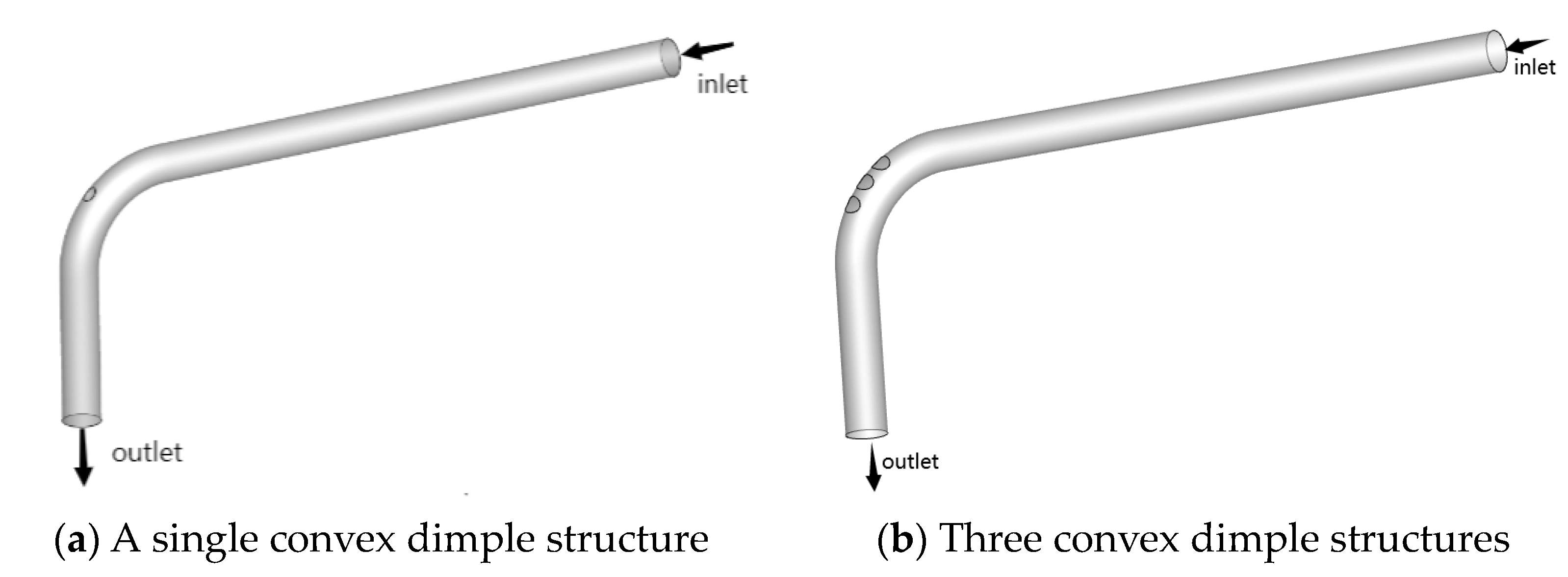
Figure 2.
Mesh diagram of bends with convex dimples.

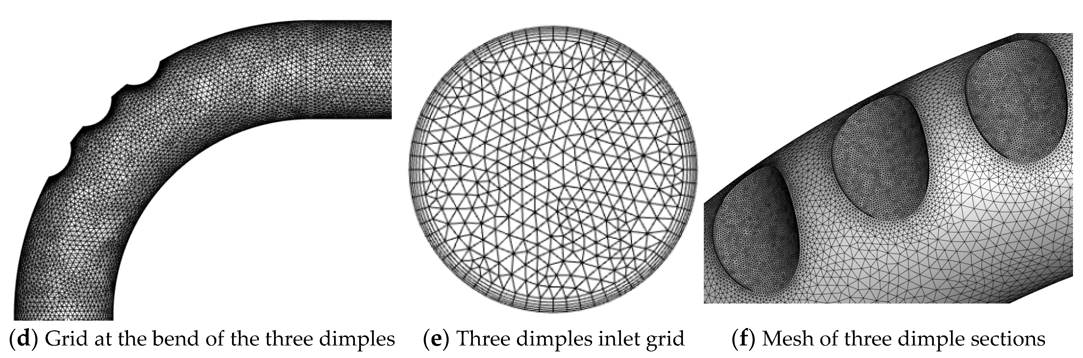
Figure 3.
Grid independence verification diagram.
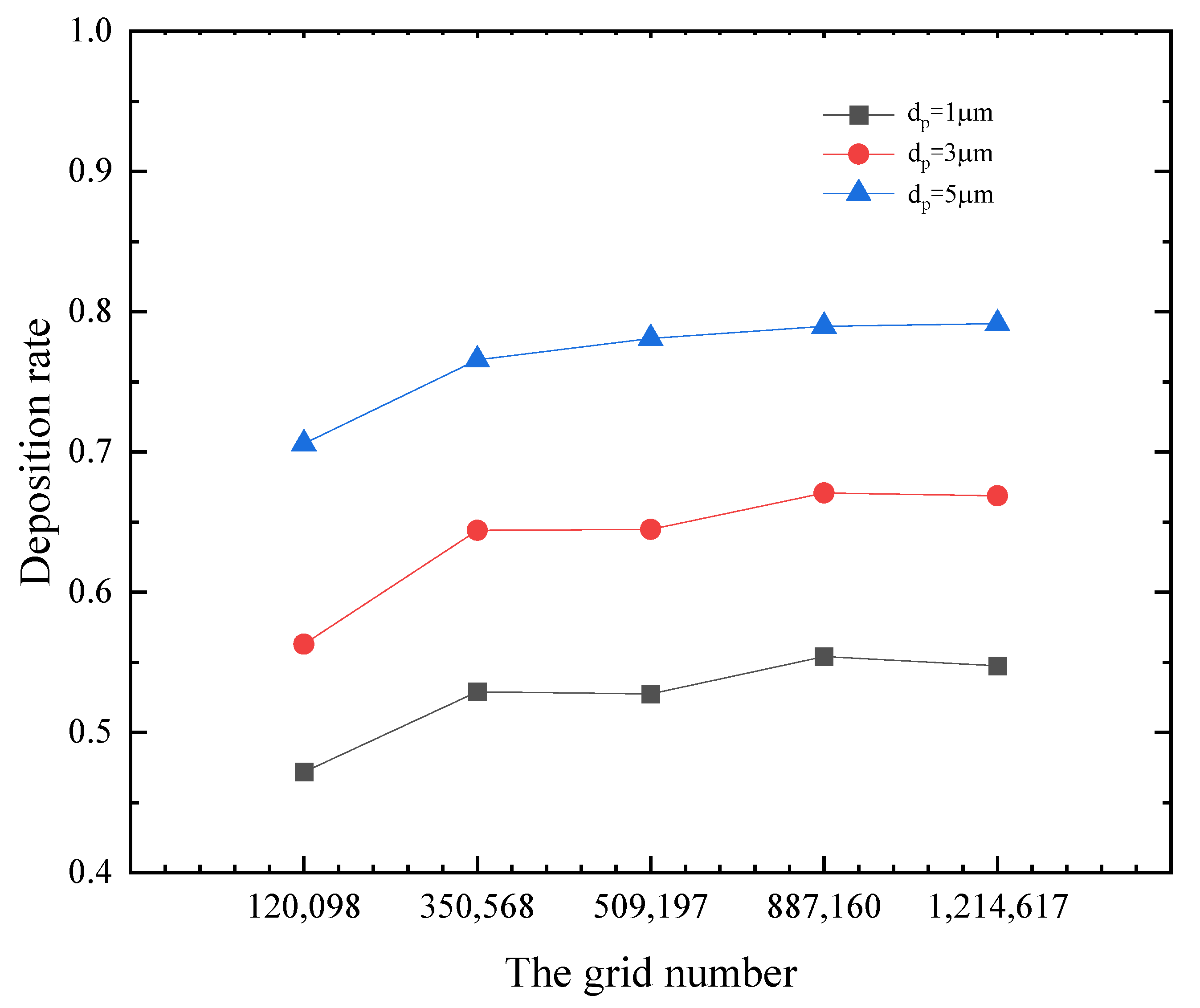
Figure 4.
Numerical validation graph of smooth channel velocity.
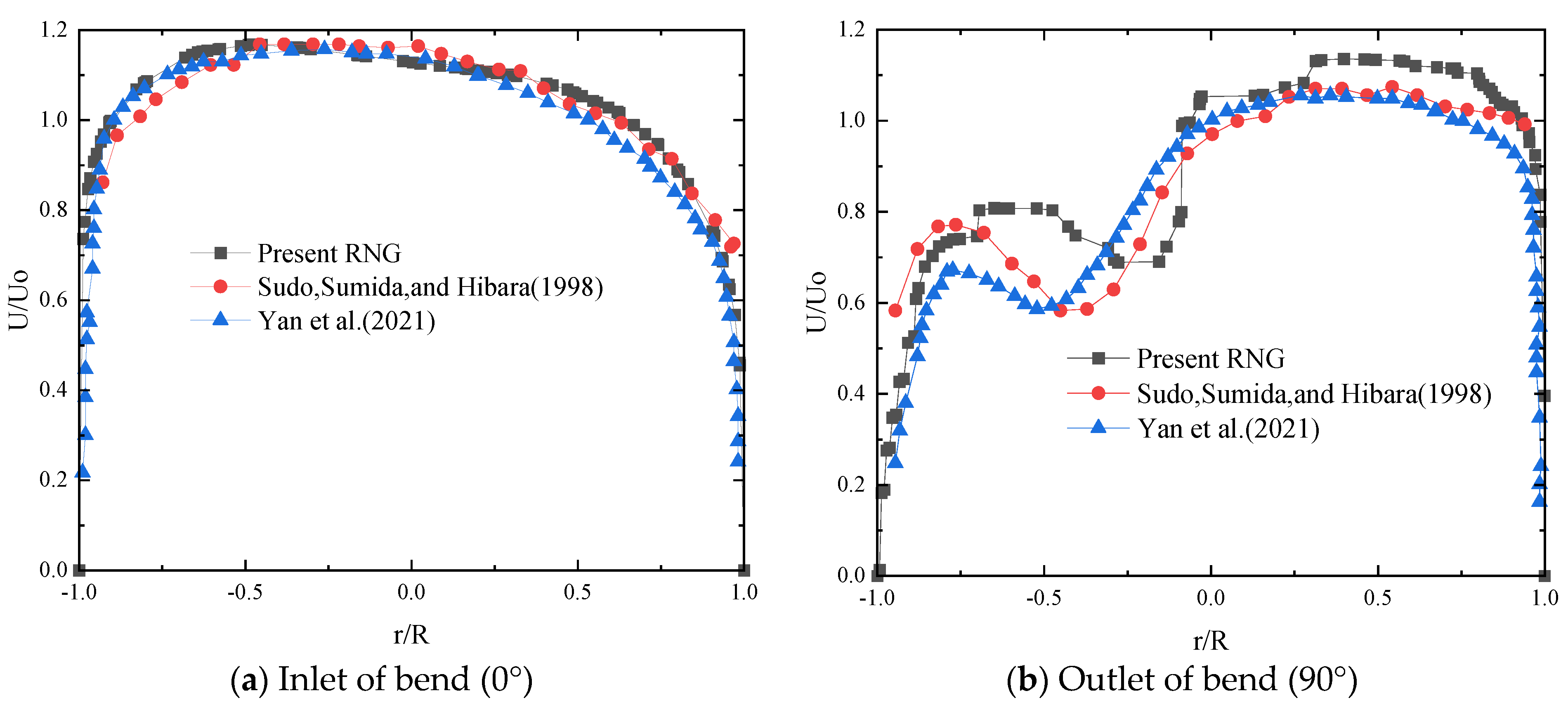
Figure 5.
Numerical validation plot of smooth channel deposition efficiency.

Figure 6.
Velocity cloud diagram.
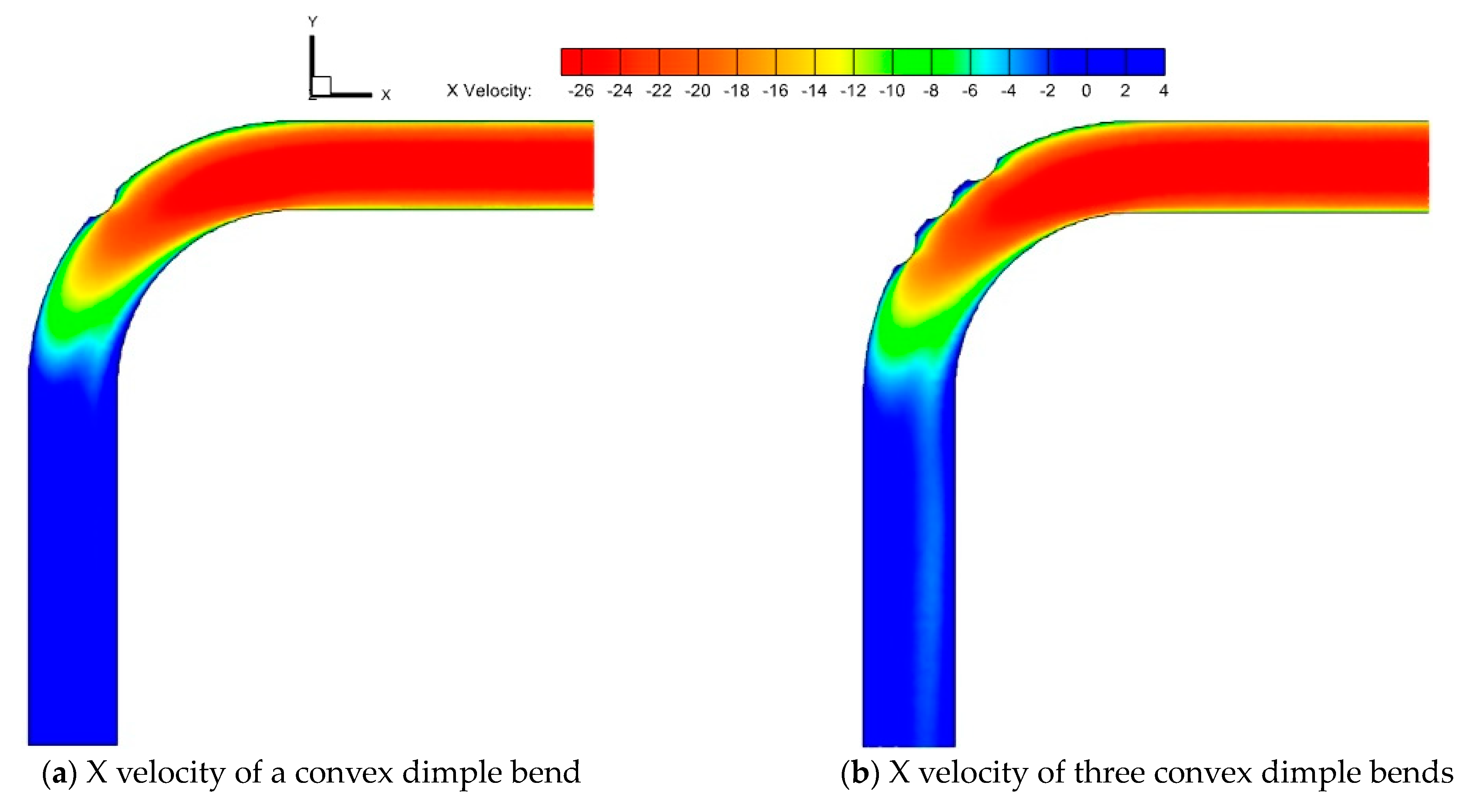
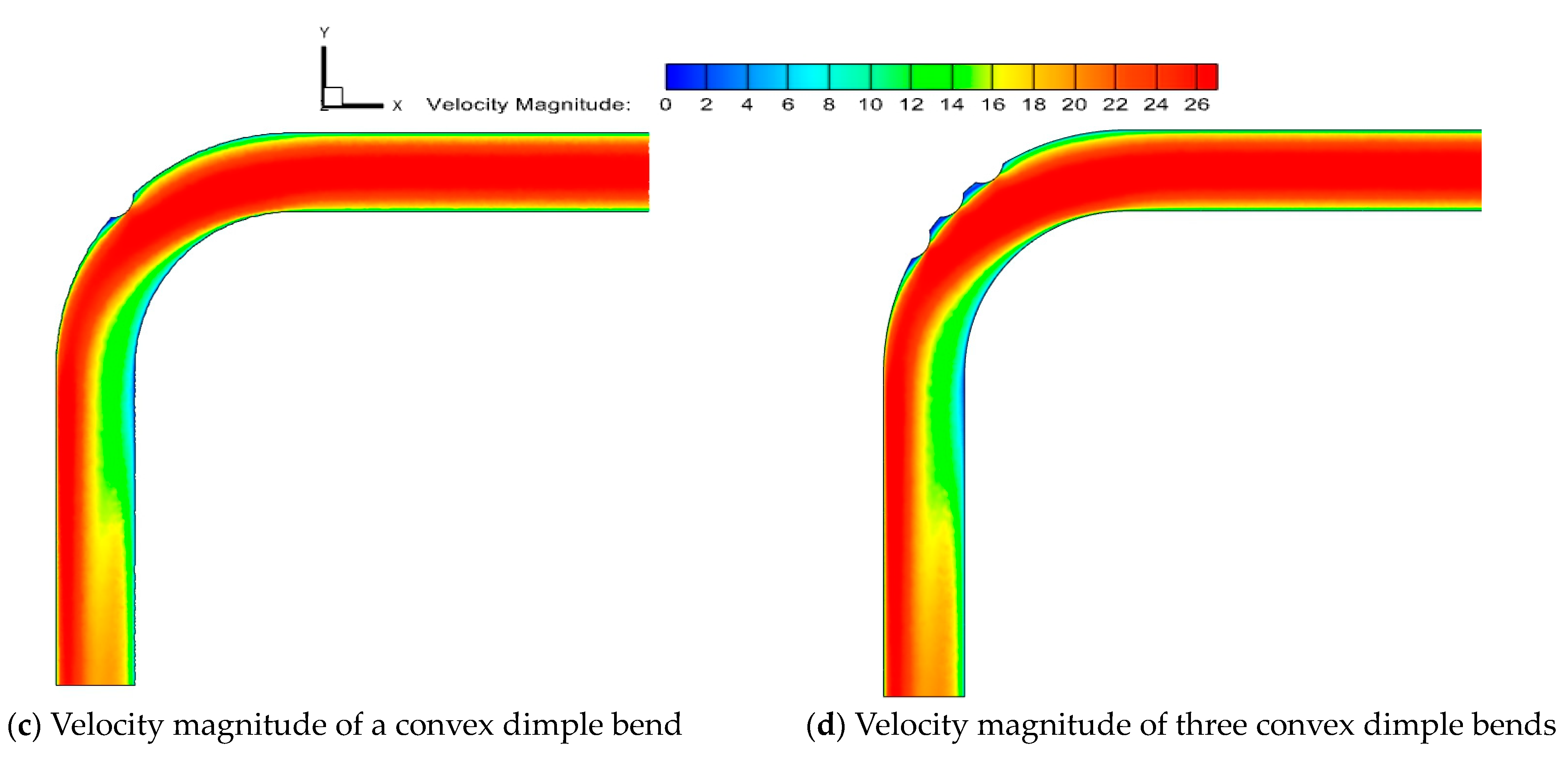
Figure 7.
Turbulent Kinetic Energy (TKE) values and flow field streamlines.

Figure 8.
Schematic diagram of temperature field and secondary flow at the inlet of different bends.
Figure 8.
Schematic diagram of temperature field and secondary flow at the inlet of different bends.
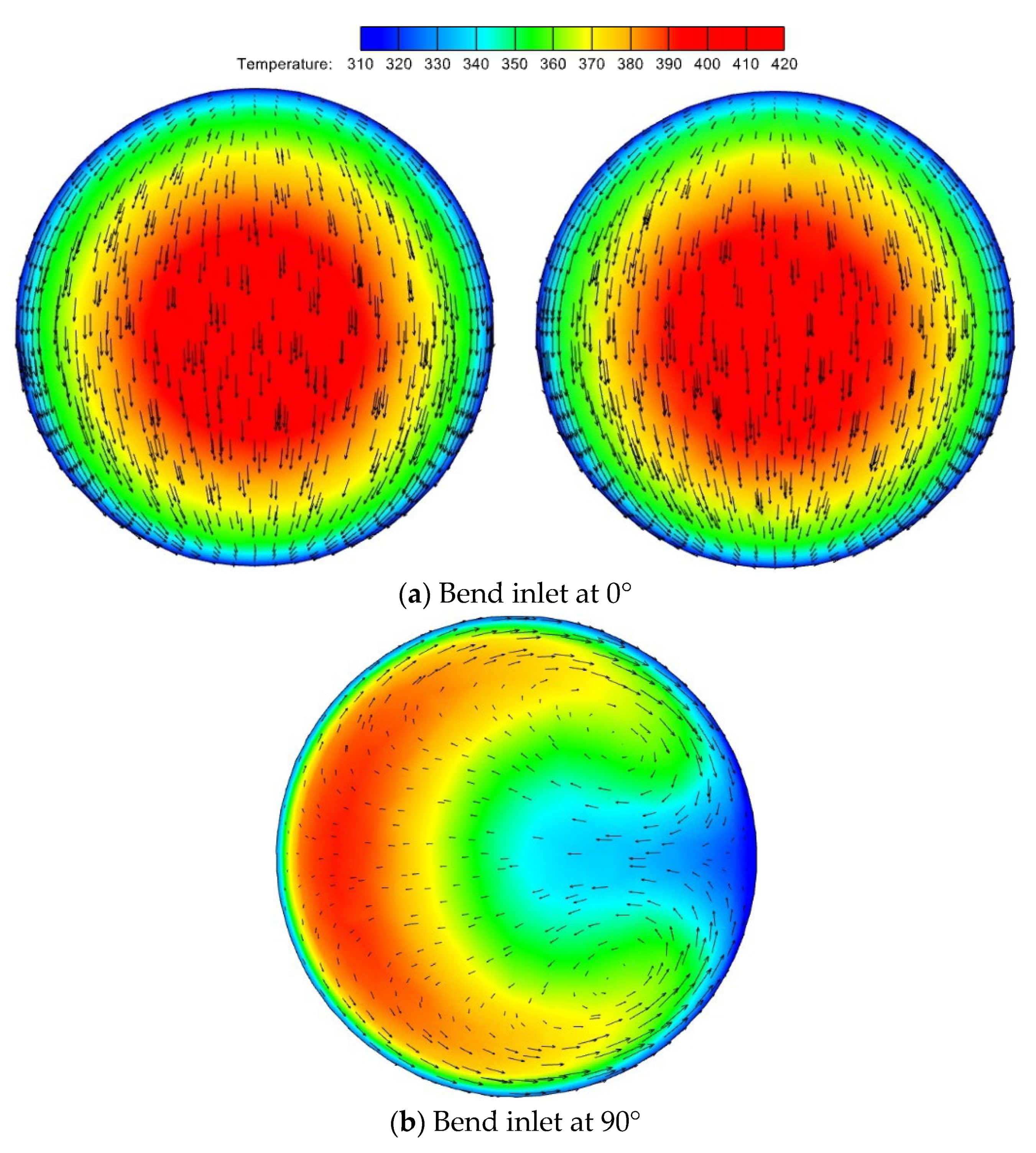
Figure 9.
Deposition plots of particles of different St in different numbers of convex dimples.

Figure 10.
Deposition of particles of different St on the wall and at the convex dimples.
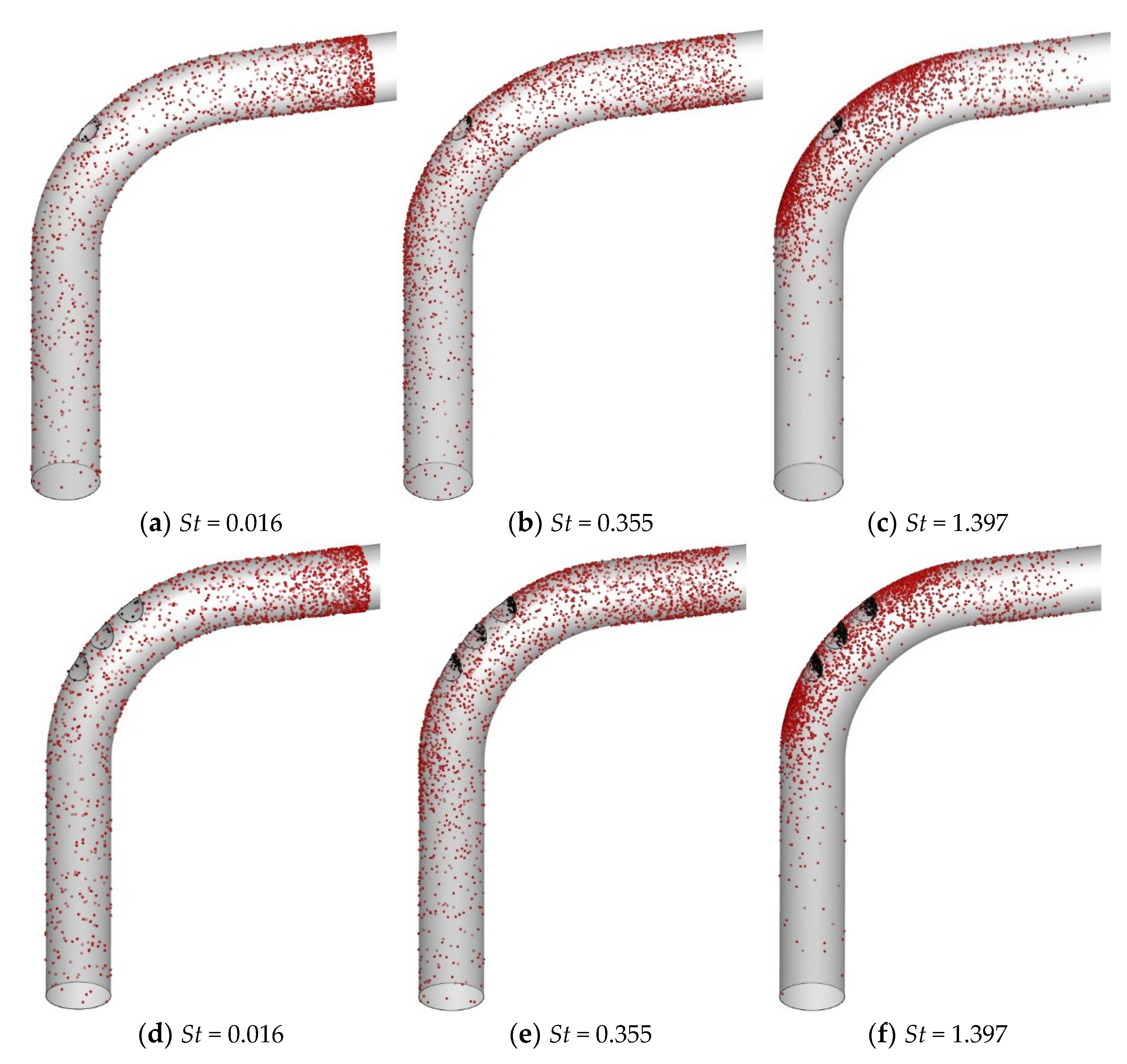
Figure 11.
Schematic representation of the deposition rate for different numbers of convex dimples.
Disclaimer/Publisher’s Note: The statements, opinions and data contained in all publications are solely those of the individual author(s) and contributor(s) and not of MDPI and/or the editor(s). MDPI and/or the editor(s) disclaim responsibility for any injury to people or property resulting from any ideas, methods, instructions or products referred to in the content. |
© 2024 by the authors. Licensee MDPI, Basel, Switzerland. This article is an open access article distributed under the terms and conditions of the Creative Commons Attribution (CC BY) license (https://creativecommons.org/licenses/by/4.0/).
Share and Cite
MDPI and ACS Style
Hua, D.; Chang, X.; Liao, M.; Han, Z.; Lu, H. A CFD Study of Particulate Deposition on Dimple-Type Flue Walls of Coal-Fired Power Plants. Coatings 2024, 14, 526. https://doi.org/10.3390/coatings14050526
AMA Style
Hua D, Chang X, Liao M, Han Z, Lu H. A CFD Study of Particulate Deposition on Dimple-Type Flue Walls of Coal-Fired Power Plants. Coatings. 2024; 14(5):526. https://doi.org/10.3390/coatings14050526
Chicago/Turabian StyleHua, Dong, Xiqiang Chang, Mengke Liao, Zunshi Han, and Hao Lu. 2024. "A CFD Study of Particulate Deposition on Dimple-Type Flue Walls of Coal-Fired Power Plants" Coatings 14, no. 5: 526. https://doi.org/10.3390/coatings14050526
Note that from the first issue of 2016, this journal uses article numbers instead of page numbers. See further details here.