
Effect of Electrochemically Deposited MgO Coating on Printable Perovskite Solar Cell Performance

 ,
,
Abstract
:1. Introduction
2. Materials and Methods
3. Results and Discussion
4. Conclusions
Acknowledgements
Author Contributions
Conflicts of Interest
References
- NREL Best Research-Cell Efficiencies. Available online: http://www.nrel.gov/pv/assets/images/efficiency_chart.jpg (accessed on 15 December 2016).
- Kojima, A.; Teshima, K.; Shirai, Y.; Miyasaka, T. Organometal Halide Perovskites as Visible-Light Sensitizers for Photovoltaic Cells. J. Am. Chem. Soc. 2009, 131, 6050–6051. [Google Scholar] [CrossRef] [PubMed]
- Lee, M.M.; Teuscher, J.; Miyasaka, T.; Murakami, T.N.; Snaith, H.J. Efficient hybrid solar cells based on meso-superstructured organometal halide perovskites. Science 2012, 338, 643–647. [Google Scholar] [CrossRef] [PubMed]
- Jeng, J.Y.; Chen, K.C.; Chiang, T.Y.; Lin, P.Y.; Tsai, T.D.; Chang, Y.C.; Guo, T.F.; Chen, P.; Wen, T.C.; Hsu, Y.J. Nickel oxide electrode interlayer in CH3NH3PbI3 perovskite/PCBM planar-heterojunction hybrid solar cells. Adv. Mater. 2014, 26, 4107–4113. [Google Scholar] [CrossRef] [PubMed]
- Qin, P.; Tanaka, S.; Ito, S.; Tetreault, N.; Manabe, K.; Nishino, H.; Nazeeruddin, M.K.; Tzel, M.G.A.; Grätzel, M. Inorganic hole conductor-based lead halide perovskite solar cells with 12.4% conversion efficiency. Nat. Commun. 2014, 5, 1–6. [Google Scholar] [CrossRef] [PubMed]
- Mei, A.; Li, X.; Liu, L.; Ku, Z.; Liu, T.; Rong, Y.; Xu, M.; Hu, M.; Chen, J.; Yang, Y.; et al. A hole-conductor–free, fully printable mesoscopic perovskite solar cell with high stability. Science 2014, 345, 295–298. [Google Scholar] [CrossRef] [PubMed]
- Baranwal, A.K.; Kanaya, S.; Peiris, T.A.N.; Mizuta, G.; Nishina, T.; Kanda, H.; Miyasaka, T.; Segawa, H.; Ito, S. 100 °C Thermal Stability of Printable Perovskite Solar Cells Using Porous Carbon Counter Electrodes. ChemSusChem 2016, 9, 2604–2608. [Google Scholar] [CrossRef] [PubMed]
- Guo, D.; Yu, J.; Fan, K.; Zou, H.; He, B. Nanosheet-based printable perovskite solar cells. Sol. Energy Mater. Sol. Cells 2017, 159, 518–525. [Google Scholar] [CrossRef]
- Park, N.-G.; Grätzel, M.; Miyasaka, T.; Zhu, K.; Emery, K. Towards stable and commercially available perovskite solar cells. Nat. Energy 2016, 1, 16152. [Google Scholar] [CrossRef]
- Han, G.S.; Chung, H.S.; Kim, B.J.; Kim, D.H.; Lee, J.W.; Swain, B.S.; Mahmood, K.; Yoo, J.S.; Park, N.-G.; Lee, J.H.; et al. Retarding charge recombination in perovskite solar cells using ultrathin MgO-coated TiO2 nanoparticulate films. J. Mater. Chem. A 2015, 3, 9160–9164. [Google Scholar] [CrossRef]
- Kulkarni, A.; Jena, A.K.; Chen, H.W.; Sanehira, Y.; Ikegami, M.; Miyasaka, T. Revealing and reducing the possible recombination loss within TiO2 compact layer by incorporating MgO layer in perovskite solar cells. Sol. Energy 2016, 136, 379–384. [Google Scholar] [CrossRef]
- Ball, J.M.; Lee, M.M.; Hey, A.; Snaith, H.J. Low-temperature processed meso-superstructured to thin-film perovskite solar cells. Energy Environ. Sci. 2013, 6, 1739–1743. [Google Scholar] [CrossRef]
- Peiris, T.A.N.; Senthilarasu, S.; Wijayantha, K.G.U. Enhanced Performance of Flexible Dye-Sensitized Solar Cells: Electrodeposition of Mg(OH)2 on a Nanocrystalline TiO2 Electrode. J. Phys. Chem. C 2012, 116, 1211–1218. [Google Scholar] [CrossRef]
- Peiris, T.A.N.; Wijayantha, K.G.U.; García-Cañadas, J. Insights into mechanical compression and the enhancement in performance by Mg(OH)2 coating in flexible dye sensitized solar cells. Phys. Chem. Chem. Phys. 2014, 16, 2912–2919. [Google Scholar] [CrossRef] [PubMed]
- Taguchi, T.; Zhang, X.; Sutanto, I.; Tokuhiro, K.; Rao, T.N. Improving the performance of solid-state dye-sensitized solar cell using MgO-coated TiO2 nanoporous film. Chem. Commun 2003, 2480–2481. [Google Scholar] [CrossRef]
- Lee, S.; Kim, J.Y.; Hong, K.S.; Jung, H.S.; Lee, J.K.; Shin, H. Enhancement of the photoelectric performance of dye-sensitized solar cells by using a CaCO3-coated TiO2 nanoparticle film as an electrode. Sol. Energy Mater. Sol. Cells 2006, 90, 2405–2412. [Google Scholar] [CrossRef]
- Liu, L.; Mei, A.; Liu, T.; Jiang, P.; Sheng, Y.; Zhang, L.; Han, H. Fully Printable Mesoscopic Perovskite Solar Cells with Organic Silane Self-Assembled Monolayer. J. Am. Chem. Soc. 2015, 137, 1790–1793. [Google Scholar] [CrossRef] [PubMed]
- Zuo, L.; Gu, Z.; Ye, T.; Fu, W.; Wu, G.; Li, H.; Chen, H. Enhanced photovoltaic performance of CH3NH3PbI3 perovskite solar cells through interfacial engineering using self-assembling monolayer. J. Am. Chem. Soc. 2015, 137, 2674–2679. [Google Scholar] [CrossRef] [PubMed]
- Wang, J.; Qin, M.; Tao, H.; Ke, W.; Chen, Z.; Wan, J.; Qin, P.; Xiong, L.; Lei, H.; Yu, H.; et al. Performance enhancement of perovskite solar cells with Mg-doped TiO2 compact film as the hole-blocking layer. Appl. Phys. Lett. 2015, 106, 121104. [Google Scholar] [CrossRef]
- Ke, W.; Fang, G.; Wan, J.; Tao, H.; Liu, Q.; Xiong, L.; Qin, P.; Wang, J.; Lei, H.; Yang, G.; et al. Efficient hole-blocking layer-free planar halide perovskite thin-film solar cells. Nat. Commun. 2015, 6, 6700. [Google Scholar] [CrossRef] [PubMed]
- Liu, D.; Yang, J.; Kelly, T.L. Compact layer free perovskite solar cells with 13.5% efficiency. J. Am. Chem. Soc. 2014, 136, 17116–17122. [Google Scholar] [CrossRef] [PubMed]
- Hernandez, S.; Ottone, C.; Varetti, S.; Fontana, M.; Pugliese, D.; Saracco, G.; Bonelli, B.; Armandi, M. Spin-coated vs. electrodeposited Mn oxide films as water oxidation catalysts. Materials 2016, 9, 296. [Google Scholar] [CrossRef]
- Dharmadasa, I.M.; Haigh, J. Strengths and Advantages of Electrodeposition as a Semiconductor Growth Technique for Applications in Macroelectronic Devices. J. Electrochem. Soc. 2006, 153, G47–G52. [Google Scholar] [CrossRef]
- Wessels, K.; Minnermann, M.; Rathousky, J.; Wark, M.; Oekermann, T. Influence of Calcination Temperature on the Photoelectrochemical and Photocatalytic Properties of Porous TiO2 Films Electrodeposited from Ti(IV)-Alkoxide Solution. J. Phys. Chem. C 2008, 112, 15122–15128. [Google Scholar] [CrossRef]
- Zou, G.; Liu, R.; Chen, W. Highly textural lamellar mesostructured magnesium hydroxide via a cathodic electrodeposition process. Mater. Lett. 2007, 61, 1990–1993. [Google Scholar] [CrossRef]
- Lv, Y.; Zhang, Z.; Lai, Y.; Li, J.; Liu, Y. Formation mechanism for planes (011) and (001) oriented Mg(OH)2 films electrodeposited on SnO2 coating glass. CrystEngComm 2011, 13, 3848–3851. [Google Scholar] [CrossRef]
- Liu, M.; Wang, Y.; Chen, L.; Zhang, Y.; Lin, Z. Mg(OH)2 supported nanoscale zero valent iron enhancing the removal of Pb(II) from aqueous solution. ACS Appl. Mater. Interfaces 2015, 7, 7961–7969. [Google Scholar] [CrossRef] [PubMed]

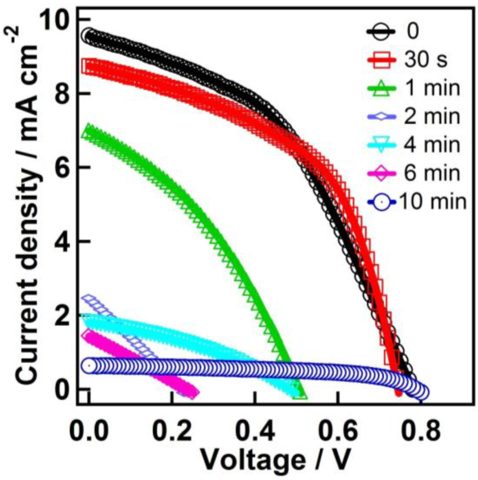
| Time | Jsc (mA·cm−2) | Voc (V) | Fill Factor | PCE (%) |
|---|---|---|---|---|
| 0 | 9.30 ± 0.23 | 0.78 ± 0.01 | 0.44 ± 0.01 | 3.19 ± 0.14 |
| 30 s | 8.48 ± 0.38 | 0.75 ± 0.01 | 0.52 ± 0.01 | 3.26 ± 0.15 |
| 1 min | 6.32 ± 0.68 | 0.48 ± 0.04 | 0.36 ± 0.01 | 1.10 ± 0.20 |
| 2 min | 2.26 ± 0.17 | 0.20 ± 0.02 | 0.26 ± 0.01 | 0.12 ± 0.02 |
| 4 min | 1.69 ± 0.19 | 0.47 ± 0.03 | 0.34 ± 0.02 | 0.27 ± 0.06 |
| 6 min | 1.32 ± 0.16 | 0.22 ± 0.03 | 0.26 ± 0.01 | 0.07 ± 0.02 |
| 10 min | 0.61 ± 0.03 | 0.79 ± 0.01 | 0.53 ± 0.01 | 0.26 ± 0.01 |
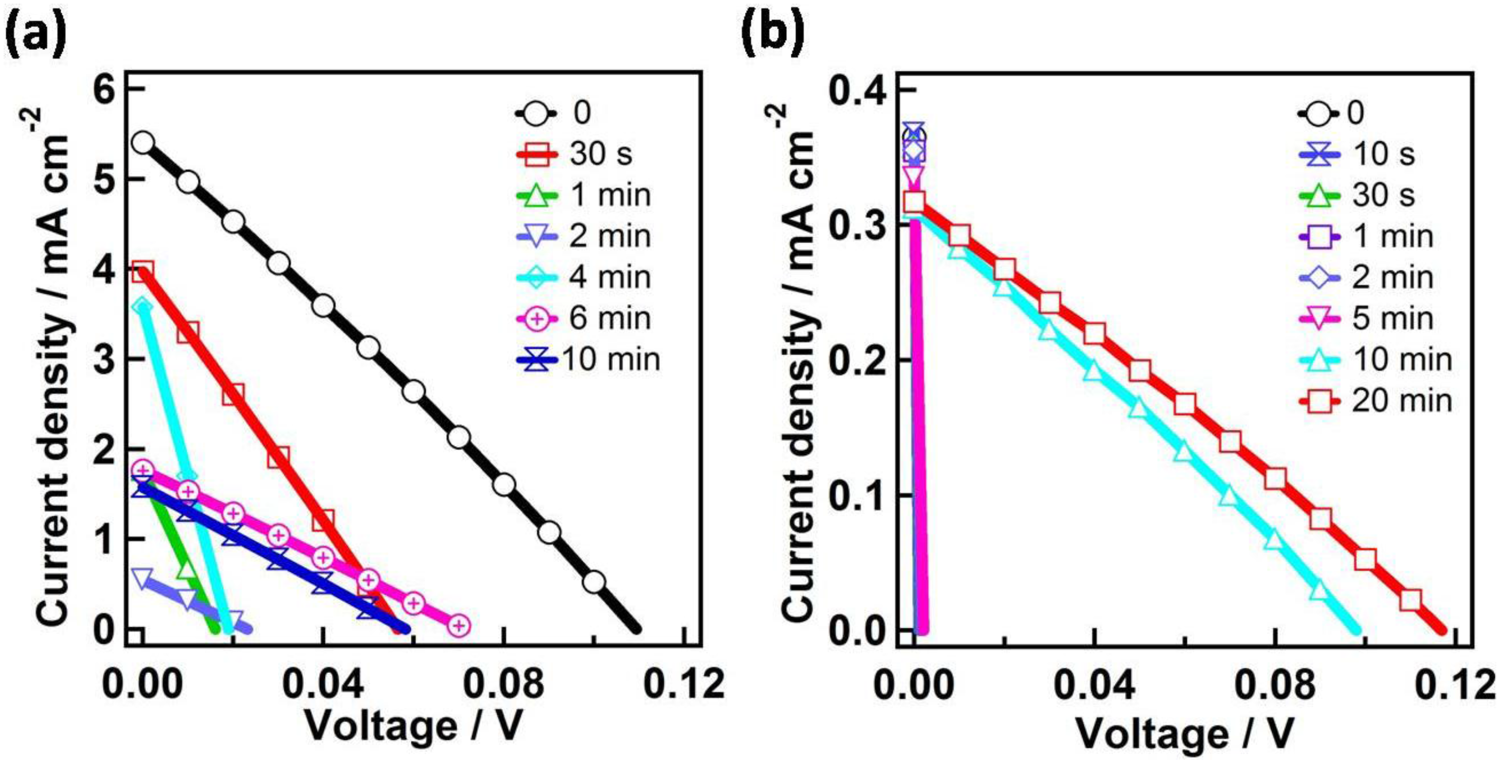
| Time (min) | Jsc (mA·cm−2) | Voc (V) | Fill Factor | PCE (%) |
|---|---|---|---|---|
| Device C | ||||
| 0 | 4.99 ± 0.56 | 0.10 ± 0.01 | 0.26 ± 0.01 | 0.14 ± 0.03 |
| 0.5 | 3.75 ± 0.51 | 0.06 ± 0.01 | 0.26 ± 0.01 | 0.05 ± 0.01 |
| 1 | 1.67 ± 0.09 | 0.02 ± 0.01 | 0.25 ± 0.01 | 0.009 ± 0.002 |
| 2 | 0.53 ± 0.03 | 0.021 ± 0.002 | 0.25 ± 0.01 | 0.0029 ± 0.0002 |
| 4 | 3.45 ± 0.22 | 0.019 ± 0.002 | 0.243 ± 0.006 | 0.02 ± 0.01 |
| 6 | 1.74 ± 0.03 | 0.071 ± 0.001 | 0.26 ± 0.01 | 0.032 ± 0.001 |
| 10 | 1.55 ± 0.04 | 0.058 ± 0.001 | 0.251 ± 0.002 | 0.023 ± 0.001 |
| Device D | ||||
| 10 | 0.31 ± 0.01 | 0.097 ± 0.001 | 0.27 ± 0.01 | 0.0079 ± 0.0001 |
| 20 | 0.32 ± 0.01 | 0.12 ± 0.01 | 0.27 ± 0.01 | 0.0099 ± 0.0002 |
© 2017 by the authors. Licensee MDPI, Basel, Switzerland. This article is an open access article distributed under the terms and conditions of the Creative Commons Attribution (CC BY) license ( http://creativecommons.org/licenses/by/4.0/).
Share and Cite
Peiris, T.A.N.; Baranwal, A.K.; Kanda, H.; Fukumoto, S.; Kanaya, S.; Bessho, T.; Cojocaru, L.; Miyasaka, T.; Segawa, H.; Ito, S. Effect of Electrochemically Deposited MgO Coating on Printable Perovskite Solar Cell Performance. Coatings 2017, 7, 36. https://doi.org/10.3390/coatings7030036
Peiris TAN, Baranwal AK, Kanda H, Fukumoto S, Kanaya S, Bessho T, Cojocaru L, Miyasaka T, Segawa H, Ito S. Effect of Electrochemically Deposited MgO Coating on Printable Perovskite Solar Cell Performance. Coatings. 2017; 7(3):36. https://doi.org/10.3390/coatings7030036
Chicago/Turabian StylePeiris, T. A. Nirmal, Ajay K. Baranwal, Hiroyuki Kanda, Shouta Fukumoto, Shusaku Kanaya, Takeru Bessho, Ludmila Cojocaru, Tsutomu Miyasaka, Hiroshi Segawa, and Seigo Ito. 2017. "Effect of Electrochemically Deposited MgO Coating on Printable Perovskite Solar Cell Performance" Coatings 7, no. 3: 36. https://doi.org/10.3390/coatings7030036