
The Electronic and Elastic Properties of Si Atom Doping in TiN: A First-Principles Calculation

School of Mechanical Engineering, Inner Mongolia University of Science & Technology, Baotou 014010, China
*
Author to whom correspondence should be addressed.
Coatings 2018, 8(1), 4; https://doi.org/10.3390/coatings8010004
Submission received: 28 August 2017
/
Revised: 5 December 2017
/
Accepted: 8 December 2017
/
Published: 21 December 2017
(This article belongs to the Special Issue Advanced Ceramic Coatings and Interfaces)
Abstract
:The elastic properties and electronic structure of interfaces in Ti–Si–N nanocomposite films were calculated using first principles based on density functional theory (DFT). The results showed that the mechanical moduli of the single-substitution interface (1Si–6N) were higher than those of the double-substitution interface and interstitial interface (1Si–4Ti4N). The single-substitution interface (1Si–6N) was revealed to be characterized as the more elastically isotropic structure in different directions, whereas the Young’s moduli significantly varied in different directions in the interstitial interface (1Si–4Ti4N). The electronic structures of interfaces indicated that the structures were conductors with intersecting bands. Strongly delocalized d states of titanium and silicon ions were spread over a wide region of about 10–12 eV and were strongly hybridized with the nitrogen 2p states. The overall appearance of the calculated cross-sections of the electron density difference changed drastically.
1. Introduction
Depositing superhard (H ≥ 40 GPa) nanocomposite films [1] of transition metal nitrides (TMN) with Si (Ti–Si–N, Nb–Si–N, Zr–Si–N) has recently been attempted, whereas understanding of their superhard properties has been researched for almost two decades. The superhard nanocomposite structure films of nanocrystal TMN in an interface was comprised of a Si atom band with N or Ti, and these films possess high elastic moduli [2,3]. However, the structures of interface and nanocrystals give rise to those with different elastic and electronic properties. More importantly, the anisotropic Young’s moduli or elastic properties of the interface or nanocrystal affected the hardness of films.
Studies on the structure and properties of interfaces in Ti–Si–N nanocomposite films were conducted more by the method of experiment and theoretical calculation. In 2006, Hao et al. reported their ab initio study of Ti–Si–N superhard coatings. Their investigation results indicated that the super-hardness of Ti–Si–N coatings is related to the preferential formation of TiN (111) polar interfaces with a thin β-Si3N4-derived layer [4,5,6]. In 2005, 2006 and 2007 Söderberg et al. reported a transmission electron microscopy examination that showed a transition from epitaxially-stabilized growth of crystalline SiNx to amorphous growth as the layer thickness increased from 0.3 nm to 0.8 nm [7,8,9]. In 2007, and in accordance with the HRTEM and ab initio studies, Kong et al. and Hultman et al. respectively denoted that the interface in superhard TiN–SiN nanocomposites is crystalline [10,11]. In 2009 and 2010, Zhang et al. found that a small distortion of the Si–N bond could stabilize the SiN interface sandwiched between fcc (001)–TiN crystallites with their ab initio DFT studies [12,13]. Furthermore, in 2010, Marten et al. reported their theoretical study on the stability of the (001) and (111) interfaces of TiN with one monolayer of B1–SiNx, and indicated that the dynamic stability of the structures of the SiNx tissue phase is critical in understanding the nanocomposites [14,15]. In 2011 and 2012, Volodymyr [16,17] investigated heterostructures consisting of one monolayer of interfacial SixNy inserted between several monolayers of thick slabs of B1(NaCl)-TiN (001) and (111) in the temperature range of 0 K to 1400 K by using first-principles quantum molecular dynamics (QMD) calculations. The most stable (001) B1-derived heterostructure with a Si0.75N interface consisted of both tetrahedrally- and octahedrally-coordinated silicon atoms. A comparison with the results obtained by earlier “static” ab initio calculations [12,13] at 0 K shows the significant advantage of the QMD calculations, which accounted for the effects of thermal activation of structural reconstructions.
The interface structure formed by Si becomes the focus of discussion in Ti–Si–N. The substitution solid solution structures of Si atom bond with the N or Ti atom in the Ti–Si–N nanocomposite films were discussed in the reported by the Zhang et al. [12,13]. However, the solid solution of interstitial would form during the process of doping. The doping Si atom bond with the N or Ti that formed the interface structure based the composite structure of grain and interfaces. Thus, the substitution and interstitial interfaces were determined by the stability of the doping structure, in which the Si atom occupies the N atom or the interstitial site between the TiN grains.
The elastic stiffness constants and elastic compliance constants of the substitution and interstitial interfaces were calculated. The calculation results of the interfaces were compared with the crystal of the TiN grains in the Ti–Si–N nanocomposite films. Then, the directional dependence of the Young’s moduli of the interfaces was described by the method of visualization in different directions. The electronic structure of the interfaces was investigated by calculating the charge density, band structure, and density of state (DOS).
2. Details of the Calculations
The calculations were performed using the VASP code, which was based on DFT [18,19,20,21]. The plane wave cut-off energy was 400 eV, the smearing value (SIGMA) was 0.05 eV, ISMEAR = 0, and SIGMA = 0.1. The periodic boundary condition was used. The calculated relaxation ISIF upon retaining the original cell volume and shape was 2; the precisions of the electron and ion relaxation convergence were 10−4 and 10−3 eV. The Brillouin zone was sampled with the Monkhorst–Pack k-point grid during self-consistent calculation to identify the electronic ground state. A 5 × 5 × 3 k-point mesh was utilized for the slab calculation. Prior to the calculation of the evolution of the particle behaviour, a lattice constant of 0.4262 nm was determined by optimizing the TiN crystalline; the value was close to the experimental value of 0.4242 nm. The free energies of the Ti, N and Si atoms were −2.501, −3.271, and −0.771 eV, respectively, based on the spin-polarized method [22].
The stable structure of substitution interface (1Si–6N) and interstitial interface (1Si–4Ti4N) in Ti–Si–N nanocomposite films were calculated [22]. To investigate the stability and mechanical properties, the stable structure of the double-substitution interface was additionally calculated. The cohesive energy of the double-substitution interface was 820.5 eV. The cohesive energy between the atoms was obtained using Equation (1):
where Ecohesive is the cohesive energy; Ecrystal is the total energy of all the atoms relaxed in the calculated bulk of the interface; nAtoms is the number of Ti, Si and N atoms; and EAtom represents the atomic energy of Ti, Si and N [22].
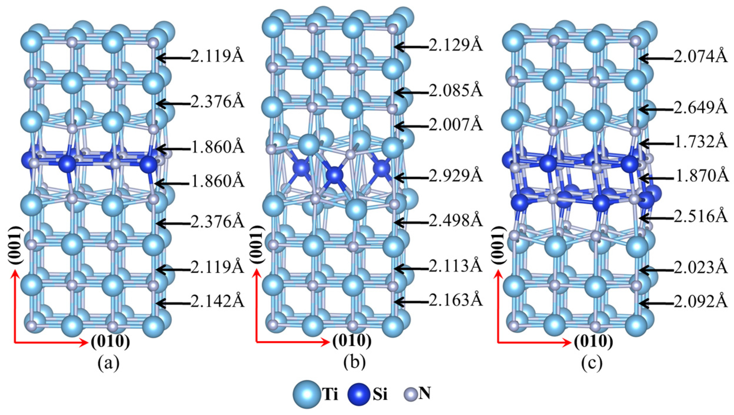
The mechanical properties of interfaces were calculated with super cells that contained up to eight atomic planes, with each atom layer in the 4 × 4 × 8 model containing 16 atoms, which corresponded to 128 atoms in a 0.85 × 0.85 × 1.7 nm3 super cell. The configuration of the substitution interface was constructed from 64 N atoms and 56 Ti atoms, with eight Si atoms occupying the sites of eight interlayer Ti atoms (see Figure 1a). The configuration of the interstitial interface was made from 64 N atoms and 64 Ti atoms, with three Si atoms occupying the hollow sites (HL) of the interlayer (see Figure 1b). Finally, the configuration of the double-substitution interface was made from 64 N atoms and 48 Ti atoms, with 16 Si atoms occupying the sites of 16 Ti interlayer atoms (see Figure 1c). The details of the configuration and bond lengths between atoms of the interfaces are shown in Figure 1.
3. Results and Discussion
3.1. The Elastic Properties of the Interfaces
A set of DFT calculations were carried out at different strains and then the appropriate fit was performed to assess the elastic constants. The quadratic curve was described by the relationship of total energy and strain of interfacial structures. The high order polynomials had been obtained by fitted the quadratic curve. The quadratic coefficient (A1) was extracted in the high order polynomials. The elastic constants of 3(C11 − C12) can be calculated by the equation A1/(6 × V) × 160.2. Here, V is the total volume of the interface structure. The 3(C11 − C12) was directly obtained by Equation (2), where the interfaces configuration were applied the tetragonal strain. The 3(C11 + 2C12)/2 was directly obtained using Equation (3), where the configuration was applied to the expansion or shrinkage strain. Additionally, the volume conservation was maintained with the strain condition and applying rhomb strain to the interface (see Equation (4)) could yield C44 parallel to the interface. Meanwhile, applying rhomb strain to the interface (see Equation (5)) could yield the C44 that was perpendicular to the interface. The shear modulus G, bulk modulus B and the Young’s modulus E can be obtained by G = (C11 − C12)/2, B = (C11 + 2C12)/3 and Equation (6), respectively [23,24]. These constants and the modulus of TiN, were calculated by the first principles method at zero external pressure and the results are listed in Table 1. Comparison with other literature data of TiN crystalline (both calculation [25] and experimentation [26], also shown in Table 1) yielded good agreement and consistency in this study.
where ε1 is the tetragonal strain, δ is the strain values, ε2 is the expansion or shrinkage strain, ε3 and ε4 denote rhomb strain parallel and perpendicular to the interface respectively, E is the Young’s modulus, B is the bulk modulus, G is the shear modulus.
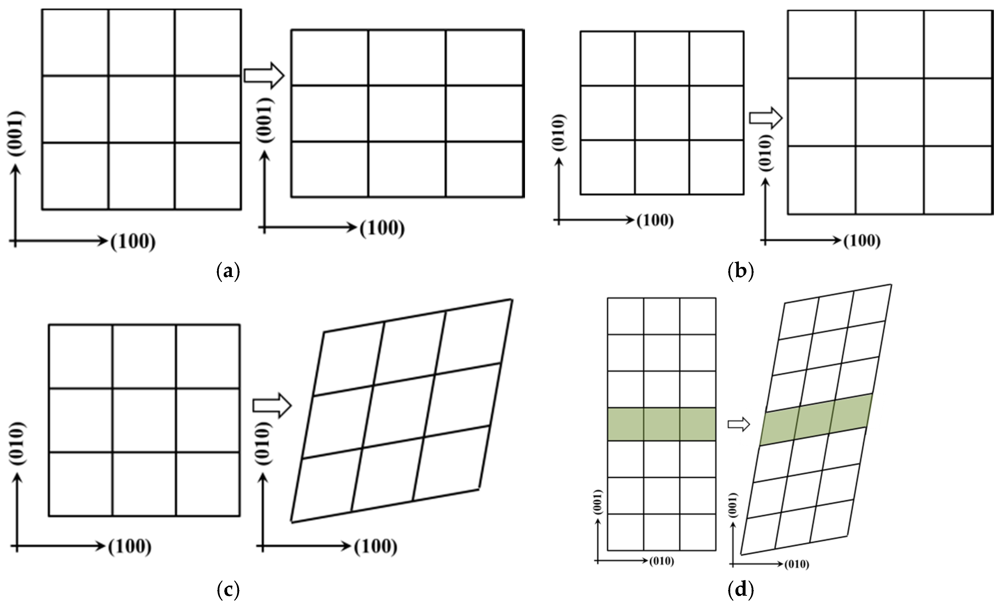
Tetragonal expansion or shrinkage (EOS) and rhomb strain form were described by the matrix Equations (2)–(4) and the configurations are shown in Figure 2a–d, respectively. Here, ε denotes the strain forms and δ is the strain value. For Equation (2), positive strain (δ > 0) is applied to the structure to expand along the direction of x and y, as well as to shrink along the z direction, to maintain the volume conservation (see in Figure 2a). The positive strain (δ > 0) is applied to the structure that is expanding along the x, y and z directions, or volume expansion, in Equation (3) (see Figure 2b). For Equation (4), positive strain (δ > 0) is applied to the structure that is deformed in parallel with the counter-clockwise direction along x and y (see in Figure 2c,d) to conserve the structure volume that was expanding along the direction of z.
The conditions of mechanical stability of these interface configurations were C44 > 0, C11 > |C12| and C11 + 2C12 > 0 [27]. These conditions are applicable for substitution, interstitial, and double-substitution interfaces in Ti–Si–N, which indicated their structural and mechanical stability at zero external pressure. Comparison of the TiN showed that the mechanical properties of the interfaces were lower than those of TiN, except C12 and C44. Strength at the interface is less than that of the grain in Ti–Si–N nanocomposite films. The elastic constants (C11, C12 and C44) and modulus (G, B, E) of the substitution interface were close with that of the TiN grain. Compared with TiN, the C11 of interfaces decreased while C12 increased, which led to the decline of the shear modulus G. The mechanical properties of parallel shear (C44) of each interface were stronger from the calculation results (see Table 2) and the strain type of C44. The features of bond strength in the coordinate direction of <001>, <010> and <100> were determined by C11, C22 and C33, respectively, in the structure of the interfaces. C11 = C22 = C33 in the cubic structure. The bond strength of single substitution in the coordinate direction of <001>, <010> and <100> was greater than those of the interstitial and the double-substitution interface. Compared with TiN, the modulus B and G of single substitution have decreased, but its strength of compression and shear stress were higher than those of other two types of interfaces. The material stiffness of the Young’s modulus E of single substitution were higher than those of the other two types of interfaces in the coordinate direction of <001>, <010> and <100> in Ti–Si–N.
The mechanical isotropy of TiN grains and interfaces was investigated and the isotropic three-dimensional view of the Young’s modulus is shown by Equation (7) in the orthorhombic system.
where l1 = sin θ cos φ, l2 = sin θ sin φ, and l3 = cos θ; S44 = 1/C44, S11 – S12 = (C11–C12)−1 and S11 + 2S12 = (C11 + 2C12)−1.
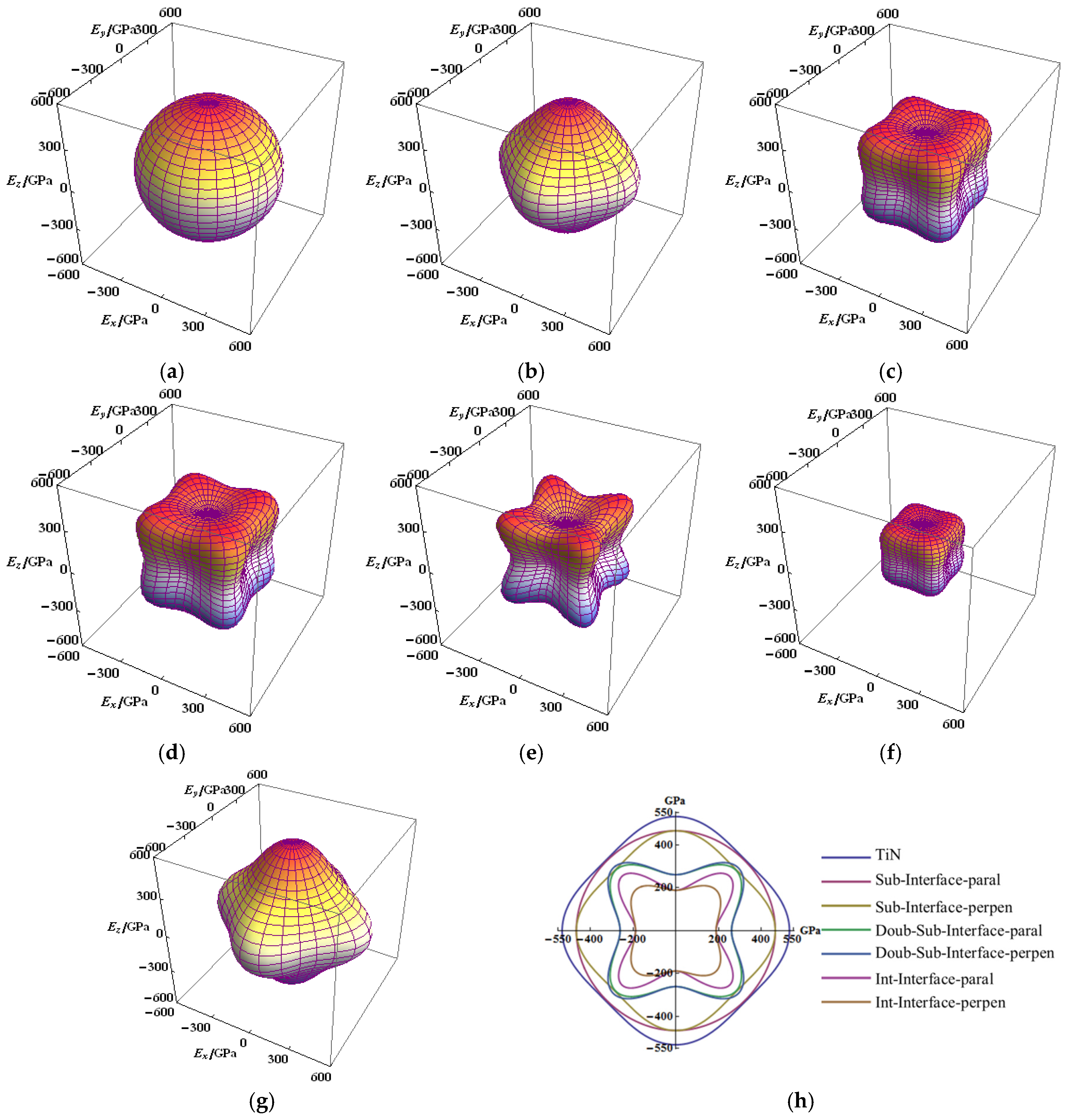
From the figure denoting the anisotropic elastic modulus, the anisotropy of Young’s modulus (E) of TiN and the single-substitution interface are not significantly prominent, which can be considered as isotropic (Figure 3a,b,g). The E of single substitution in direction of parallel to the interface was displayed to be fully isotropic (see in Figure 3a). Compared with the TiN, the maximum value of the E of single substitution were not significantly decreased, whether in the parallel or perpendicular direction to the interface in the Ti–Si–N. Compared with the single-substitution interface, the E of double-substitution and interstitial interfaces were evidently revealed to be anisotropic (Figure 3c–f). The anisotropic property parallel and perpendicular to the interface is highly similar with that of double substitution, which almost overlapped in the top view of the x-y plane (Figure 3h). Although the anisotropic E perpendicular to the interface is not substantial, the maximum value of EY of the interstitial interface evidently decreased (Figure 3h). The strength E of single substitution in a direction along the axis (x, y and z) was prominent, which is the same as that of TiN. The strength E was weak along the major axis, strong along the body diagonal direction and the space view is similar to those of the double-substitution and interstitial interfaces.
The mechanical properties and cohesive energy of substitution were decreased with an increase in the interface layer thickness, whereas the isotropic Young’s modulus exhibited poor performance. The interstitial interface showed poor mechanical properties and isotropic Young’s modulus, despite having higher cohesive energy. The nanocrystalline TiN fell off easily from the Ti–Si–N under experiments where shear load is applied, a result of the friction performance of Ti–Si–N [28]. One reason is that the interface strength is weak, which led to the nanocrystalline TiN falling off. The TiN is not easy to break, but the interface structure is easily broken, resulting in failure under shear load. The mechanical properties of the interface are worse than that of TiN.
3.2. The Electronic Structure of the Interfaces
The charge density distribution of interfaces in Ti–Si–N is shown in Figure 4. The dark blue particles are Si atoms in the interfaces. A stable structure is formed by the combination of long and short bonds between the N atoms and Si atoms in substitution interface, and the charge distribution of electrons is uneven around the Si atoms. More electrons were transferred to the short Si–N position outside the Si nucleus (Figure 4).
The energy band structure and density of states (range: 0–3.5 electrons/eV) of TiN, the B1–SiN substitution interface and the 1Si–4N4Ti interstitial interface are shown in Figure 5, accordingly. The overlapping phenomenon occurred in the energy band structures of TiN, B1–SiN, and 1Si–4N4Ti, thereby exhibiting metallic properties. The electronic structure of Ti, Si, and N is 3d24s2, 2s22p3 and 3s23p3, respectively. The hybrid orbital from the 2p for Ti atoms and 3d for N in TiN crystal band structure contributed to the energy density of states between −10 eV to 5 eV. The peak of the density of states contributed together with 2p for Ti and 3d for N atoms near the Fermi surface. As the energy band occupied by 3d states for Ti across the Fermi surface (see Figure 5a, the red line shown in bold), the metallic property of TiN was mainly derived from 3d states for Ti (see the partial density of state of atom in Supplementary Figure S1c,d). The hybrid orbital from the 2p for Si and 2p for N in B1–SiN structure of the substitution interface (Figure 5b) contributed to the energy density of states between −10 eV to 5 eV. As the energy band occupied by the 2p for Si and 2p for N across the Fermi surface (see Figure 5b, the red line shown in bold), the metallic property of B1-SiN was mainly derived from 2p states for Si (see the partial density of state of atom in Supplementary Figure S2c,d). The hybrid orbital from the 3d for Ti, 2p for Si, and 2p for N in the 1Si–4N4Ti interstitial interface (Figure 5c) contributed to the energy density of states between −10 eV to 5 eV h. As the energy band occupied by the 3d for Ti, 2p for Si, and 2p for N across the Fermi surface (see Figure 5c, the red line shown in bold), the metallic property of 1Si–4N4Ti is mainly derived from 3d states for Ti and 2p states for Si (see the partial density of state of atom in Supplementary Figure S3c,d).
A non-metallic band exists at the lowest energy position under the Fermi level in the energy band structure of TiN, B1–SiN, and 1Si–4N4Ti. This non-metallic band was contributed by the 2s states of N. Notably, the electron states of Si were distributed in the valence band and conduction band of DOS in the electronic structure of the interfaces, which overlap with the 2p orbital of the N at the valence band region. The difference of the electronic structure in the substitution and interstitial interface was the contribution of the valence band Fermi level from Si, comprehensively shown in Figure 5b,c. The electron states of Si 2p and 2s were the nearly equal distribution of the valence and conduction bands in the interstitial interface. Under the influence of the contribution with Ti and Si, a concentrated density of states and high peak appeared at THE Fermi surface in the band structure of THE interstitial interface. However, Si contributed mostly to the DOS of the valence band, which only a slight density of states contributed to the conduction band in the substitution interface. Therefore, the processes of charge density transfer from Si to N occurred in the substitution interface. The lower and scattered DOS was distributed near the Fermi surface. Overall, the bonds of Ti–N and Si–N are relatively strong polar covalent bonds in Ti–Si–N. The strong polar covalent bonds were formatted with an electron hybridization orbital in grains and the interfaces, thus imparting greater hardness upon this structure of nanocomposite films.
The DOS peak maximum and distribution regions of substitution and interstitial interfaces are less than that of TiN in the total DOS (see Figure 5, range: 0–3.5 electrons/eV). This may be the cause that the mechanical properties of substitution and interstitial interfaces are less than that of TiN. The Fermi level TiN and interfaces are not at the maximum peak position in total DOS, indicating that they are stable. However, the Fermi level of TiN was close to the bottom in the DOS, while the Fermi level of substitution and interstitial interfaces were located in a smaller peak.
4. Conclusions
The mechanical properties of single or double substitution and interstitial interfaces have been investigated. The elastic constants of the single-substitution interface were higher than those of the other two types. However, the C44 and C12 of all interfaces were lower than those of the TiN in Ti–Si–N. The calculated tensors of the elastic constants were used for the analysis and visualization of the directional dependence of the Young’s moduli. The result of the isotropic Young’s modulus showed that the single-substitution interface reflected better isotropy in different directions. The maximum value of the Young’s moduli of other types of interfaces decreased, while anisotropy was more prominent. The mechanical properties and cohesive energy of the substitution interface were correspondingly decreased with the increase in the interface layer thickness. Meanwhile, the isotropic Young’s modulus of the substitution interface showed poor performance. The mechanical properties and isotropic Young’s modulus of the interstitial interface were unsatisfactory but the interface had higher cohesive energy. The electronic structures of TiN and the interfaces indicate that the structures were conductors with intersecting energy bands. The energy band structures of the interfaces were contributed by a hybrid orbital of electrons from the 2p for Si, 3d for Ti and 2p for N. The bond configuration of grains and interfaces are components with stronger polar covalent bonds in Ti–Si–N.
Supplementary Materials
The following are available online at https://www.mdpi.com/2079-6412/8/1/4/s1, Figure S1: Band structure, density of state (DOS) and partial density of state (PDOS) of B1–NaCl structure of TiN; Figure S2: Band structure, density of state (DOS) and partial density of state (PDOS) of B1–NaCl structure of B1-SiN; Figure S3: Band structure, density of state (DOS) and partial density of state (PDOS) of 1Si–4N4Ti.
Acknowledgments
The National Natural Science Foundation of China (grant No. 51702170, 51562031), the Educational Commission of Inner Mongolia of China (grant No. NJZY17172), National Natural Science Foundation of Inner Mongolia Autonomous Region (grant No. 2015MS0554), supported this research work.
Author Contributions
Xuejie Liu conceived and designed the study; Yuan Ren performed the calculations; Xiangbao Gao, Chao Zhang and Shiyang Sun analysed the data and participated in the discussions; and Yuan Ren and Xuejie Liu wrote the paper.
Conflicts of Interest
The authors declare no conflict of interest.
References
- Veprek, S.; Reiprich, S. A concept for the design of novel superhard coatings. Thin Solid Films 1995, 268, 64–71. [Google Scholar] [CrossRef]
- Veprek, S. The search for novel, superhard materials. J. Vac. Sci. Technol. A 1999, 17, 2401–2420. [Google Scholar] [CrossRef]
- Chen, X.; Xu, J.F.; Xiong, W.H.; Zhou, S.Q.; Chen, S. Mechanochemical synthesis of Ti(C,N) nanopowder from titaniumand melamine. Int. J. Refract. Met. Hard Mater. 2015, 50, 152–156. [Google Scholar] [CrossRef]
- Hao, S.; Delley, B.; Veprek, S.; Stampfl, C. Superhard nitride-based nanocomposites: Role of interfaces and effect of impurities. Phys. Rev. Lett. 2006, 97, 086102. [Google Scholar] [CrossRef] [PubMed]
- Hao, S.; Delley, B.; Stampfl, C. Role of oxygen in TiN(111)/SixNy/TiN(111) interfaces: Implications for superhard nanocrystalline nc-TiN/a-Si3N4 nanocomposites. Phys. Rev. B 2006, 74, 035424. [Google Scholar] [CrossRef]
- Hao, S.; Delley, B.; Stampfl, C. Structure and properties of TiN(111)/SixNy/TiN(111) interfaces in superhard nanocomposites: First-principles investigations. Phys. Rev. B 2006, 74, 035402. [Google Scholar] [CrossRef]
- Söderberg, H.; Odén, M.; Molina-Aldareguia, J.M.; Hultman, L. Nanostructure formation during deposition of TiN/SiNx nanomultilayer films by reactive dual magnetron sputtering. J. Appl. Phys. 2005, 97, 114327. [Google Scholar] [CrossRef]
- Söderberg, H.; Larsson, T.; Hultman, L.; Molina-Aldareguia, J.M.; Odén, M. Epitaxial stabilization of cubic-SiNx in TiN/SiNx multilayers. Appl. Phys. Lett. 2006, 88, 191902. [Google Scholar] [CrossRef]
- Söderberg, H.; Odén, M.; Flink, A.; Birch, J.; Persson, P.O.Å.; Beckers, M.; Hultman, L. Growth and characterization of TiN/SiN (001) superlattice films. J. Mater. Res. 2007, 22, 3255–3264. [Google Scholar] [CrossRef]
- Hultman, L.; Bareño, J.; Flink, A.; Söderberg, H.; Larsson, K.; Petrova, V.; Odén, M.; Greene, J.E.; Petrov, I. Interface structure in superhard TiN-SiN nanolaminates and nanocomposites: Film growth experiments and ab initio calculations. Phys. Rev. B 2007, 75, 155437. [Google Scholar] [CrossRef]
- Kong, M.; Zhao, W.; Wei, L.; Li, G. Investigations on the microstructure and hardening mechanism of TiN/Si3N4 nanocomposite coatings. J. Phys. D Appl. Phys. 2007, 40, 2858–2863. [Google Scholar] [CrossRef]
- Zhang, R.F.; Argon, A.S.; Veprek, S. Electronic structure, stability, and mechanism of the decohesion and shear of interfaces in superhard nanocomposites and heterostructures. Phys. Rev. B 2009, 79, 245426. [Google Scholar] [CrossRef]
- Zhang, R.F.; Argon, A.S.; Veprek, S. Understanding why the thinnest SiNx interface in transition-metal nitrides is stronger than the ideal bulk crystal. Phys. Rev. B 2010, 81, 245418. [Google Scholar] [CrossRef]
- Marten, T.; Isaev, E.I.; Alling, B.; Hultman, L.; Abrikosov, I.A. Single-monolayer SiNx embedded in TiN: A first-principles study. Phys. Rev. B 2010, 81, 212102. [Google Scholar] [CrossRef]
- Marten, T.; Alling, B.; Isaev, E.; Lind, H.; Tasnadi, F.; Hultman, L.; Abrikosov, I. First-principles study of the SiNx/TiN (001) interface. Phys. Rev. B 2012, 85, 104106. [Google Scholar] [CrossRef]
- Ivashchenko, V.I.; Veprek, S.; Turchi, P.E.A.; Shevchenko, V.I. Comparative first-principles study of TiN/SiNx/TiN interfaces. Phys. Rev. B 2012, 85, 195403. [Google Scholar] [CrossRef]
- Ivashchenko, V.I.; Veprek, S.; Turchi, P.E.A.; Shevchenko, V.I. First-principles study of TiN/SiC/TiN interfaces in superhard nanocomposites. Phys. Rev. B 2012, 86, 014110. [Google Scholar] [CrossRef]
- Kresse, G.; Hafner, J. Ab initio molecular dynamics for liquid metals. Phys. Rev. B 1993, 47, 558–561. [Google Scholar] [CrossRef]
- Kresse, G.; Furthmuller, J. Efficiency of ab-initio total energy calculations for metals and semiconductors using a plane-wave basis set. Comput. Mater. Sci. 1996, 6, 15–50. [Google Scholar] [CrossRef]
- Kresse, G.; Furthmuller, J. Efficient iterative schemes for ab initio total-energy calculations using a plane-wave basis set. Phys. Rev. B 1996, 54, 11169–11186. [Google Scholar] [CrossRef]
- Kresse, G.; Joubert, D. From ultrasoft pseudopotentials to the projector augmented-wave method. Phys. Rev. B 1999, 59, 1758–1775. [Google Scholar] [CrossRef]
- Liu, X.J.; Ren, Y.; Tan, X.; Sun, S.Y.; Westkaemper, E. The structure of Ti–Si–N superhard nanocomposite coatings: Ab initio study. Thin Solid Films 2011, 520, 876–880. [Google Scholar] [CrossRef]
- Brik, M.G.; Ma, C.-G. First-principles studies of the electronic and elastic properties of metal nitrides XN (X = Sc, Ti, V, Cr, Zr, Nb). Comput. Mater. Sci. 2012, 51, 380–388. [Google Scholar] [CrossRef]
- Kittel, C. Introduction to Solid State Physics, 8th ed.; John Wiley & Sons, Inc.: Hoboken, NJ, USA, 2005; p. 59. [Google Scholar]
- Yang, Y.; Lu, H.; Yu, C.; Chen, J.M. First-principles calculations of mechanical properties of TiC and TiN. J. Alloys Comp. 2009, 485, 542–547. [Google Scholar] [CrossRef]
- Kim, J.O.; Achenbach, J.D.; Mirkarimi, P.B.; Shinn, M.; Barnett, S.A. Elastic constants of single-crystal transition-metal nitride films measured by line-focus acoustic microscopy. J. Appl. Phys. 1992, 72, 1805. [Google Scholar] [CrossRef]
- Patil, S.K.R.; Khare, S.V.; Tuttle, B.R.; Bording, J.K.; Kodambaka, S. Mechanical stability of possible structures of PtN investigated using first-principles calculations. Phys. Rev. B 2006, 73, 104118. [Google Scholar] [CrossRef]
- Cheng, Y.H.; Browne, T.; Heckerman, B.; Meletis, E.I. Mechanical and tribological properties of nano composite TiSiN coatings. Surf. Coat. Technol. 2010, 204, 2123–2129. [Google Scholar] [CrossRef]
Figure 1.
The atomic structures and the variations in bond lengths of the modelled interfaces in nanocomposite structural Ti–Si–N films: (a) substitution interface (1Si–6N); (b) interstitial interface (1Si–4Ti4N); and (c) double-substitution interface.
Figure 1.
The atomic structures and the variations in bond lengths of the modelled interfaces in nanocomposite structural Ti–Si–N films: (a) substitution interface (1Si–6N); (b) interstitial interface (1Si–4Ti4N); and (c) double-substitution interface.

Figure 2.
Strain configuration of calculation mechanical properties of the interfaces in Ti–Si–N: (a) tetragon shear strain; (b) expansion or shrinkage strain; (c) rhomb strain of parallel to interface; (d) rhomb strain of perpendicular to interface.
Figure 2.
Strain configuration of calculation mechanical properties of the interfaces in Ti–Si–N: (a) tetragon shear strain; (b) expansion or shrinkage strain; (c) rhomb strain of parallel to interface; (d) rhomb strain of perpendicular to interface.

Figure 3.
Directional dependence of the Young’s moduli for interfaces of Ti–Si–N, cross-sections (in the x-y plane) of the Young’s moduli surfaces for TiN and interfaces: (a) parallel to the substitution interface (1Si–6N); (b) perpendicular to the substitution interface; (c) perpendicular to the double-substitution interface; (d) parallel to double-substitution interface; (e) parallel to the interstitial interface (1Si–4Ti4N); (f) perpendicular to the interstitial interface (1Si–4Ti4N); (g) the TiN crystal; and (h) cross-sections (in the x-y plane) of the Young’s moduli surfaces for TiN and interfaces.

Figure 4.
The charge–density of interfaces in nanocomposite structural Ti–Si–N films: (a) the front view of the substitution interface; (b) the top view of the substitution interface; (c) the top view of the interstitial interface; (d) the front view of the interstitial interface; and (e) the scale of charge density (e·nm−2).

Figure 5.
Band structure and density of state (DOS) of B1–NaCl structure of (a) TiN, (b) the B1–NaCl structure interface of SiN, (c) and the interstitial interface of 1Si–4N4Ti.
Figure 5.
Band structure and density of state (DOS) of B1–NaCl structure of (a) TiN, (b) the B1–NaCl structure interface of SiN, (c) and the interstitial interface of 1Si–4N4Ti.


Table 1.
Elastic constant of TiN.
| TiN | C11 | C12 | C44 | B | G | E | |
|---|---|---|---|---|---|---|---|
| This work Calculation | 607.038 | 117.922 | 166.695 | 280.961 | 244.558 | 568.676 | |
| Other work | Calculation [25] | 579 | 129 | 180 | 279 | 197 | 477 |
| Experimentation [26] | 625 | 165 | 163 | 318 | 187 | 469 | |
Table 2.
Elastic constants of the substitution interface (1Si–6N), double-substitution interface, and interstitial interface (1Si-4Ti4N) in Ti–Si–N nanocomposite structural films (GPa).
Table 2.
Elastic constants of the substitution interface (1Si–6N), double-substitution interface, and interstitial interface (1Si-4Ti4N) in Ti–Si–N nanocomposite structural films (GPa).
| Interfaces | C11 | C12 | C44 | B | G | E | |
|---|---|---|---|---|---|---|---|
| Parallel | Perpendicular | ||||||
| Sub-Interface | 518.730 | 131.366 | 189.023 | 152.603 | 260.487 | 193.682 | 465.640 |
| Inter-Interface | 334.536 | 197.021 | 221.599 | 120.543 | 242.859 | 68.757 | 188.485 |
| Double-Interface | 347.1537 | 145.7505 | 215.2848 | 234.3611 | 212.885 | 100.702 | 260.958 |
© 2017 by the authors. Licensee MDPI, Basel, Switzerland. This article is an open access article distributed under the terms and conditions of the Creative Commons Attribution (CC BY) license (http://creativecommons.org/licenses/by/4.0/).
Share and Cite
MDPI and ACS Style
Ren, Y.; Gao, X.; Zhang, C.; Liu, X.; Sun, S. The Electronic and Elastic Properties of Si Atom Doping in TiN: A First-Principles Calculation. Coatings 2018, 8, 4. https://doi.org/10.3390/coatings8010004
AMA Style
Ren Y, Gao X, Zhang C, Liu X, Sun S. The Electronic and Elastic Properties of Si Atom Doping in TiN: A First-Principles Calculation. Coatings. 2018; 8(1):4. https://doi.org/10.3390/coatings8010004
Chicago/Turabian StyleRen, Yuan, Xiangbao Gao, Chao Zhang, Xuejie Liu, and Shiyang Sun. 2018. "The Electronic and Elastic Properties of Si Atom Doping in TiN: A First-Principles Calculation" Coatings 8, no. 1: 4. https://doi.org/10.3390/coatings8010004
Note that from the first issue of 2016, this journal uses article numbers instead of page numbers. See further details here.