Article

TiO2 Nanocrystal Based Coatings for the Protection of Architectural Stone: The Effect of Solvents in the Spray-Coating Application for a Self-Cleaning Surfaces

by
Francesca Petronella
1,
Antonella Pagliarulo
1,†,
Alessandra Truppi
1,
Mariateresa Lettieri
2,
Maurizio Masieri
2,
Angela Calia
2,
M. Lucia Curri
1,* and
Roberto Comparelli
1,*
1
CNR-IPCF, Consiglio Nazionale delle Ricerche, Istituto per i Processi Chimico-Fisici, S.S. Bari 70126, Italy
2
CNR-IBAM, Consiglio Nazionale delle Ricerche Istituto per i Beni Archeologici e Monumentali, Prov.le Lecce-Monteroni, 73100 Lecce, Italy
*
Authors to whom correspondence should be addressed.
Present address: Department of Chemistry, Durham University, Durham DH1 3L, UK
Coatings 2018, 8(10), 356; https://doi.org/10.3390/coatings8100356
Submission received: 25 July 2018 / Revised: 1 October 2018 / Accepted: 3 October 2018 / Published: 5 October 2018
(This article belongs to the Special Issue Nanostructured Thin Films)

Abstract

:
A colloidal route was exploited to synthesize TiO2 anisotropic nanocrystal rods in shape (TiO2 NRs) with a surface chemistry suited for their dispersibility and processability in apolar organic solvents. TiO2 NRs were dispersed in chloroform and n-heptane, respectively, and the two resulting formulations were investigated to identify the optimal conditions to achieve high-quality TiO2 NR-based coatings by the spray-coating application. In particular, the two types of TiO2 NR dispersions were first sprayed on silicon chips as a model substrate in order to preliminarily investigate the effect of the solvent and of the spraying time on the morphology and uniformity of the resulting coatings. The results of the SEM and AFM characterizations of the obtained coatings indicated n-heptane as the most suited solvent for TiO2 NR dispersion. Therefore, an n-heptane dispersion of TiO2 NRs was sprayed on a highly porous limestone—Lecce stone—very commonly used as building material in historic constructions and monuments present in Apulia Region (Italy). A comprehensive physical-chemical investigation of the TiO2 NR based treatment on the surface of the stone specimens, including measurements of colour variation, static contact angle, water transfer properties, and morphological characterization were performed. Finally, the photocatalytic properties of the coatings were assessed under solar irradiation by using Lecce stone specimens and Methyl Red as a model target compound. The obtained results demonstrated that TiO2 NRs based coatings can be successfully applied by spray-coating resulting in an effective photocatalytic and hydrophobic treatment, which holds great promise as a material for the environmental protection of architectural stone in the field of cultural heritage conservation.

1. Introduction

TiO2 nanoparticles (NPs) are widely employed as building blocks for functional materials to be used in a plethora of applications, and, in particular, in the fields of energy production and environmental remediation [1]. Such a large interest is driven by the intrinsic and deeply investigated features of the nanomaterial such as its high surface area, high photoactivity, chemical stability [2], and unique surface properties (e.g. photoinduced superhydrophilicity [3]). The interaction of light of a suitable wavelength with TiO2 NPs promotes the formation of electron/hole pairs that, once migrated to the TiO2 NP surface, may react with adsorbed O2 or H2O molecules. The reaction produces a reactive oxygen species (ROS), able to promote the photocatalytic degradation (potentially to complete mineralization) of pollutants [4] both in aqueous media and at the solid/air interface, thus opening up outstanding opportunities in the field of water remediation, air pollution control, or bacteria inactivation [5]. The use of TiO2 NPs as the functional material in coatings requires their direct immobilization on surfaces or, alternatively, their incorporation in a suitable polymer matrix in order to exploit their functionalities. For example, the superhydrophobic and/or superhydrophilic surface characteristics of TiO2 NPs were exploited to convey the self-cleaning, anti-fogging and anti-wetting properties to glasses, membranes and conductive substrates [6]. Further, the incorporation of TiO2 NPs in a polymer and their application onto the surface to convey their photocatalytic function to surfaces has been purposely designed for the degradation of organic pollutants in wastewater [7], bactericidal coatings [8], and the abatement of nitrogen oxides and volatile organic compounds [9,10]. The development of functional coatings based on TiO2 NPs to protect lapideous building materials in monuments and artworks of historical and architectural interest is gaining widespread attention in the recent years [11,12]. The application of TiO2 NPs for cultural heritage conservation needs to comply with multiple requirements in order to preserve, as far as possible, the characteristics of the artworks or monuments. Indeed, a suitable coating, besides introducing effective functions for stone protection and self-cleaning, has to preserve the aesthetic features of the material, be compatible with previous treatments, and ensure stability and durability. Functional TiO2 NPs based coatings have demonstrated to be able to prevent the biodeterioration of stony surfaces [13], limit the formation of black crusts [14] and salts that may dramatically damage stony surfaces [15], and convey hydrophobic properties to the surface in order to limit the water penetration inside stone pores without affecting the aesthetic characteristics [11]. In the field of cultural heritage, TiO2 NPs are generally applied by using two distinct approaches. The first relies on the incorporation of the NPs in a polymer host matrix that may also consist of a commercial product already employed as a cleanser, protective or consolidant, like the Alpha® SI3 [15], the Rhodosil 224, the Porosil VVplus [16] and the Fosbuild FBLE 200 [17]. Although coatings resulting from the combination of TiO2 NPs and polymers may be characterized by suitable hydrophobic properties and self-cleaning activity, their application still presents critical issues. In fact, the identification of a convenient host polymer is among the most relevant questions, since organic polymer-based coatings are not stable and durable against the OH radicals generated by TiO2 upon UV irradiation [18]. As an example, superhydrophobic coatings based on TiO2 and Lumiflon® 200 demonstrated a high performance in terms of wettability. Nevertheless, for prolonged exposure times, some drawbacks, including a decrease of hydrophobicity, cracking of the coating layer, and removal of polymer from the stone surface were observed [19]. In this respect, however, hybrid organic-inorganic polymers have demonstrated to be photochemically stable [20,21]. The incorporation of TiO2 in a host matrix can cause a drop in the photocatalytic performance of TiO2 since only a fraction of TiO2 NPs at the outermost surface of the coating is, in fact, effective in the photocatalytic process [5]. Moreover, the high viscosity of the nanocomposite has been observed to limit a homogeneous coverage of the stone surface [18].
The second approach, consists of the direct application of TiO2 NPs onto the stone surface, present several advantages (provided that suitable formulations are used), as it limits the loss of photocatalytic activity due to the incorporation in a matrix, preserves the aesthetic appearance of the stone surface [22], and, since it is based on low viscosity products, is able to penetrate inside the pores of the stone and to provide uniform coatings [18]. In addition, it has been reported that the direct application of TiO2 NPs can be regarded as a suitable alternative treatment to conventional chemical biocides because anatase TiO2 NPs demonstrated to prevent the biodeterioration of monuments, with a further advantage to avoid harmful conventional chemical biocides [23]. In this perspective, a great deal of work has been devoted to comprehensively investigate the direct application of TiO2 NP-based coatings for the protection of materials in cultural heritages. Aqueous and alcoholic suspensions of TiO2 NPs obtained by acid and basic nanosols have been used to treat porous and compact limestones and have been found not to significantly affect the stone colour and its capillary absorption coefficient, while still able to convey photocatalytic properties to the treated surface, although critical issues related to the final coating morphology and composition have been observed. Indeed both alcoholic (e.g. ethanol [18,24,25]) and aqueous suspensions of TiO2 NPs, once applied on the stone surface, can result in discontinuous coatings characterized by large fissures [26,27]. TiO2 based coatings with NP sizes in the range of 10–20 nm were successfully also sprayed on travertine, resulting in a uniform coating with photocatalytic activity that preserved the stone aesthetics [28]. Promising results in terms of the aesthetic compatibility, capillary absorption coefficient, and photocatalytic activity were also achieved by applying a coating based on mesoporous anatase TiO2 from a dispersion in ethylene glycol both on Noto Stone and Carrara Marble [29]. The application of TiO2 NPs, dispersed in an organic solvent (chloroform) on stony materials was already addressed by using colloidal TiO2 NCs, rod-shaped and coordinated with oleic acid molecules (OLEA) as capping agent [30]. The casting and the dipping were used to apply the photocatalytic TiO2 nanorods (NRs) based coating on the Lecce stone (PL) with promising results in terms of photocatalytic activity, hydrophobic properties and aesthetical compatibility [30]. Such application techniques, though relevant for a preliminary investigation of TiO2 NRs based coatings, are, in fact, not thoroughly viable in view of a real scale application onto buildings and monuments.
Conversely, the spray coating that was demonstrated to be suitably cost-effectively obtained thin and crack-free films highly stable on the stone surface [31], though it may lead to inhomogeneous NP deposits [32]. In this work, we intend to use the TiO2 NRs that already showed great potential for obtaining a functional protective coating on stone [21,30], and yet assess the TiO2 NRs application by spray coating from n-heptane, as an organic volatile solvent suitable for NR dispersion.
For this purpose, a preliminary investigation of the most appropriate conditions to accomplish an effective TiO2 NRs based spray coated treatment was carried out by using silicon chips as a model substrate and then, the most suited formulation was applied to develop a functional coating on samples of a highly porous limestone—Lecce stone—very commonly used as building material in historic constructions and monuments present in Apulia Region (Italy) [24]. The physical-chemical and the photocatalytic properties of the resulting treated stone samples were finally assessed.
Remarkably, because of its porosity and chemical composition, the Lecce stone (PL) is sensitive to the damaging effects caused by water penetration [33], being composed mainly by calcium carbonate (93%–97%) with low amounts of quartz, glauconite and clay minerals, and is characterized by a high porosity (42%), with fine pore sizes, namely between 0.1 and 10 µm [27].
Among the different types of TiO2 NPs, TiO2 NRs represent a convenient nanomaterial to convey photocatalytic functions to the stone surface due to their peculiar properties. Indeed TiO2 NRs were obtained by means of a colloidal synthesis anatase in phase and with a size of 18 nm in length and 3 nm in diameter and characterized by a high processability since their surface is coordinated with organic molecules, namely oleic acid (OLEA). These TiO2 NRs have been demonstrated to possess structural and photochemical properties that make them an excellent candidate for photocatalytic applications. The anisotropy in the OLEA coated TiO2 NRs has been demonstrated to induce an increase in the lifetime of the photogenerated charge carriers that can thus, in principle, migrate to the surface with a consequent improvement of the photocatalytic activity [34,35]. Further, anatase, the main crystallographic phase of TiO2 NRs, has been widely recognized as the most photoactive phase of this semiconductor [36]. Finally, the OLEA molecules coordinating the TiO2 NRs surface have been found to not only provide stability in organic volatile solvents, resulting in optically transparent dispersions [37], but also to convey hydrophobic properties to the stone surface [30].
First, the optimization of the spray coating application was performed, investigating the effect of the solvent and the spraying time onto silicon chips used as a model substrate. Then, the most suitable conditions were applied to achieve a functional coating on the PL, as, to the best of our knowledge, n-heptane has not been so far investigated as a solvent for the spray coating application of TiO2NPs on stone. The coated stone samples were thoroughly characterized from a physical-chemical point of view and their photocatalytic activity against pollutants was investigated by using a dye as a model compound for organic contaminants in outdoor experiments in an urban environment. Remarkably, the experimental results revealed that the TiO2 NRs film obtained by spray coating conveyed photocatalytic and hydrophobic properties to the stone under the investigated conditions, keeping the aesthetic characteristics of the surface almost unaltered.

2. Materials and Methods

2.1. Materials

Titanium tetraisopropoxide (Ti(OiPr)4 or TTIP, 99.999%), trimethylamino-N-oxide dihydrate ((CH3)3NO•2H2O or TMAO, 98%), oleic acid (C18H33CO2H or OLEA, 90%) and Methyl Red (2-(4-dimethylaminophenylazo)benzoic acid—C. I. 13020, MR) were purchased from Sigma-Aldrich, Milano, Italy. All chemicals were of the highest purity available and were used as received without further purification All solvents used were of analytical grade and purchased from Sigma-Aldrich.

2.2. Synthesis of TiO2 NRs

The synthesis of TiO2 NRs was achieved by the hydrolysis and polycondensation of TTIP, following the procedure reported in [25]. The reaction was catalyzed by an aqueous solution TMAO di-hydrate that was directly injected in the reaction flask containing technical-grade OLEA as the coordinating solvent at a temperature in the range of 80–100 °C. The growth of TiO2 NRs lasted 5 days under a nitrogen atmosphere. Subsequently, TiO2 NRs were collected by precipitation, adding an excess of ethanol at ambient temperature, then isolated by centrifugation and washed three times with ethanol and n-hexane to remove the excess of OLEA. The obtained OLEA-capped TiO2 NRs were easily re-dispersed in chloroform. The presence of OLEA as the capping agent for TiO2 NRs allowed obtaining a clear dispersion, without aggregates or suspended matters.

2.3. Characterization of TiO2 NRs

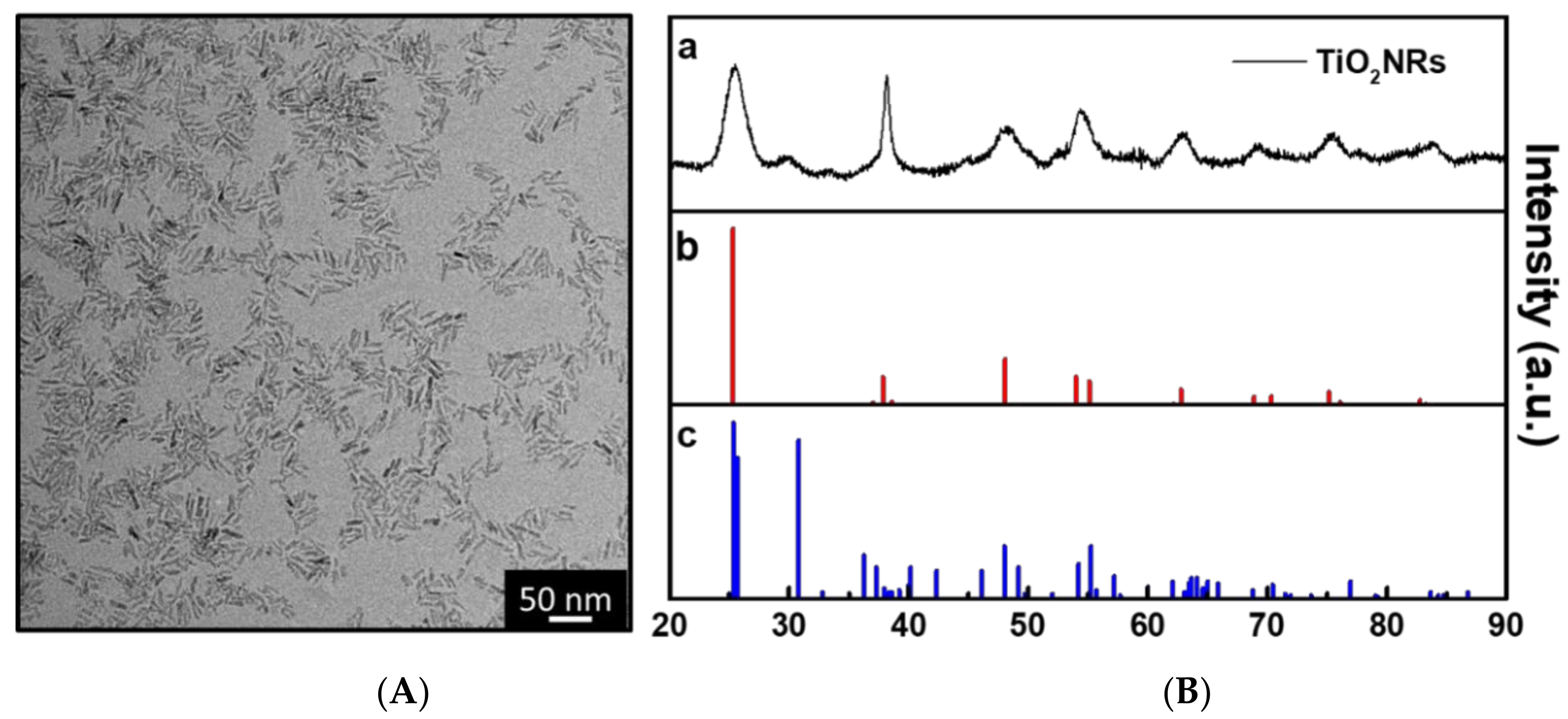
2.3.1. Transmission Electron Microscopy

Transmission electron microscopy (TEM) analysis was carried out by a JEOL JEM-1011 microscope (JEOL, Akishima, Tokyo, Japan) operating at 100 kV. The carbon TEM grid was prepared by casting 3 µL TiO2NRs 0.02 M dispersed in chloroform.

2.3.2. XRD Analysis

X-ray diffraction data (XRD) were collected at room temperature from samples of TiO2 NRs deposited onto silicon substrates. Measurements were performed by using a Bruker D8 Discover Diffractometer (Bruker AXS, Karlsruhe, Germany), equipped with a Göbel mirror, using Cu Kα radiation (λ Kα1 = 1.54056 Å and λ Kα2 = 1.54439 Å), and an energy dispersive X-ray SolX-E detector (Bruker, Karlsruhe, Germany). Data were collected at a fixed incidence angle of 5° while moving the detector in the range of 10°–120° with a step size of 0.05°.

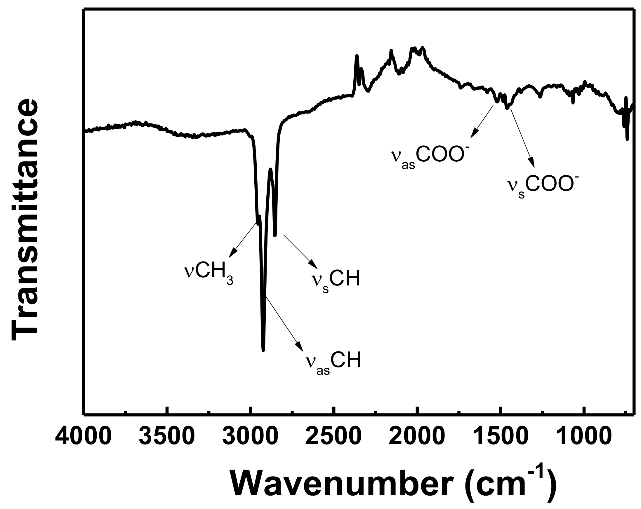
2.3.3. ATR-FTIR Spectroscopy

Mid-infrared spectra were performed with a Varian 670-IR spectrometer (Agilent Technologies, Inc., Santa Clara, CA, USA) equipped with a DTGS (deuterated triglycine sulfate) detector. The spectral resolution used for all experiments was 4 cm−1. For Attenuated Total Reflection (ATR) measurements, the internal reflection element (IRE) used was a one bounce 2 mm diameter diamond microprism. The material to be investigated was cast directly onto the internal reflection element by depositing the solution or dispersion of interest (3–5 μL) on the upper face of the diamond crystal and allowing the solvent to evaporate.

2.4. Spray-Coating Application Of TiO2 Nanorods onto the Model Substrate

The application of TiO2 NRs by spray coating on silicon chips (1 cm × 1 cm) was performed in order to preliminarily investigate the optimal conditions in terms of solvent and spraying time that, in principle, should lead to a uniform distribution of TiO2 NRs on the surface. Prior to spraying the photocatalyst dispersion on the silicon chips, the substrates were cleaned by sonication in methanol and acetone baths, respectively, rinsed with isopropanol and dried under nitrogen flow. The equipment for immobilization of TiO2 NRs by spray coating consists of a nitrogen cylinder connected to a glass nebulizer. The nebulizer contains the TiO2 NR dispersion in n-heptane or in chloroform, 0.02 M in Ti. The silicon substrate was placed 6 cm from the nebulizer and a nitrogen flux of 3.5 bar was used to generate an aerosol of TiO2 NRs for coating the stone surface. The nitrogen flux value, the TiO2NRs concentration and the spraying time were carefully selected in order to achieve a clear dispersion and to obtain coatings not detrimental in terms of the colour variation for the aesthetical features of the stone sample. Silicon substrates were sprayed with TiO2 NRs, according to the experimental condition reported in Table 1 (Section 3.2). Silicon substrates were prepared and characterized in triplicate and representative experimental data were reported.

2.5. Characterization of Films of TiO2 NRs on Silicon

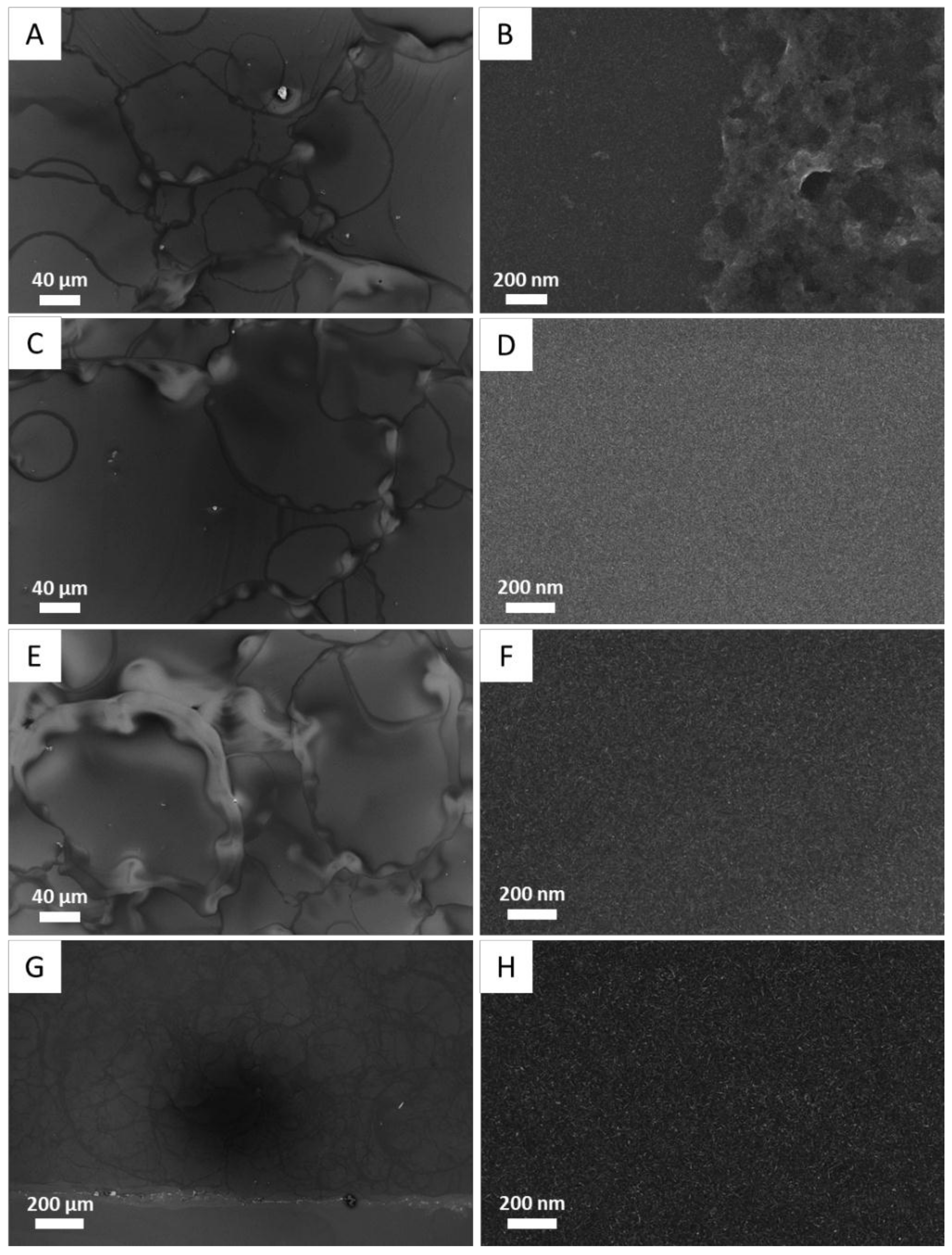
2.5.1. Scanning Electron Microscopy

A Scanning Electron Microscopy (SEM) analysis was performed with an FE-SEM (Field Emission-Scanning electron microscope) Zeiss-Sigma (Carl Zeiss Co., Oberkochen, Germany) with an operating voltage of 0.5–20 kV, equipped with an in-lens secondary detector. Silicon samples were mounted on stainless steel sample holder by using double-sided carbon tape and were grounded by silver paste.

2.5.2. Atomic Force Microscopy Analysis

Atomic force microscopy (AFM) analysis was carried out with a PSIA XE-100 SPM microscope (Park Systems Corp., Suwon, Korea) in AFM mode and cantilever with a silicon nitride tip. Topography images were recorded in non-contact mode at a scan rate of 1 Hz with a resolution of 512 × 512 pixels. The roughness (Rq) was calculated as the standard deviation of the height values measured in a selected region. It was calculated by the software XEI, Version 1.2 Image Processing Program for SPM data, developed by PSIA. For the calculation of Rq, 5 µm areas of three different regions of the same sample were considered

2.6. Spray-Coating Application of TiO2 NRs on Stone

The application of TiO2 NRs by spray coating on PL was performed on samples with dimensions 5 × 1 × 5 cm3 and 5 × 1 × 2 cm3 (l, d, h) for the physical-chemical characterization and for the photocatalytic test, respectively. Prior to spraying the photocatalyst dispersion, the stone specimens were thermally treated at 40 °C for 1 h, dried for 30 min under vacuum and finally cleaned by a mild jet of nitrogen to limit further humidity accumulation. The dispersion of TiO2 NRs (0.02 M) was sprayed by using the same experimental set up used for the experiments on silicon substrates, using n-heptane as a solvent to disperse TiO2 NRs, having been identified as the most suited solvent. The PL specimens were prepared by following the same procedure and experimental conditions described in Section 2.4. Four PL samples were coated by TiO2 NRs dispersion sprayed for increasing time, as reported in Table 3 (Section 3.3).

2.7. Characterization of TiO2 NRs Coating

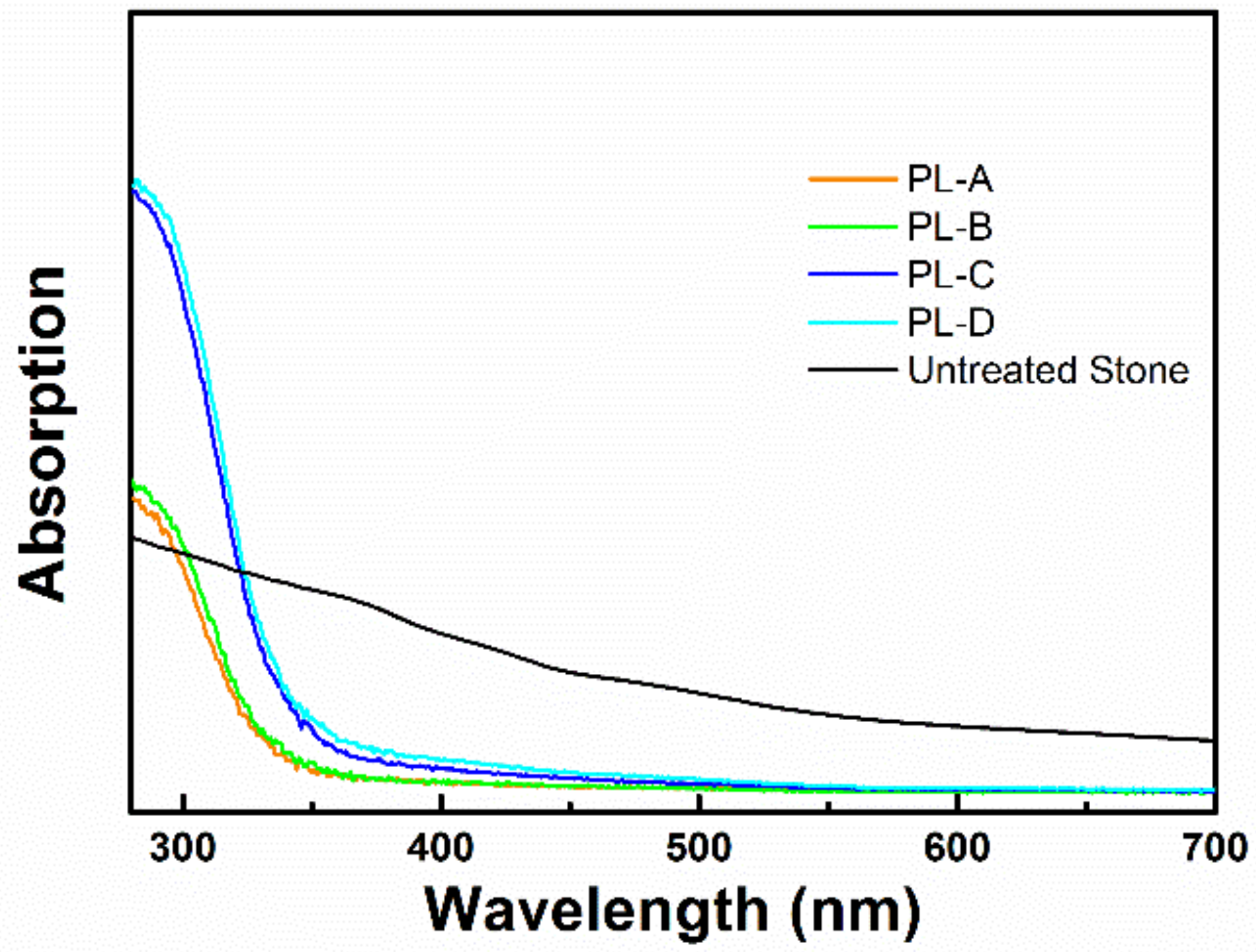
2.7.1. Diffuse Reflectance Spectroscopy

The Diffuse Reflectance Spectra (DRS) of PL were performed with a UV–Vis-near IR Cary 5 (Varian spectrophotometer, Agilent Technologies, Inc., Santa Clara, CA, USA), equipped with an integrating sphere.

2.7.2. Static Contact Angle Measurements

Measurements were taken with a Costech instrument, according to the current European Standard [38]. The specimens measuring 5 × 1 × 5 cm3 were investigated.

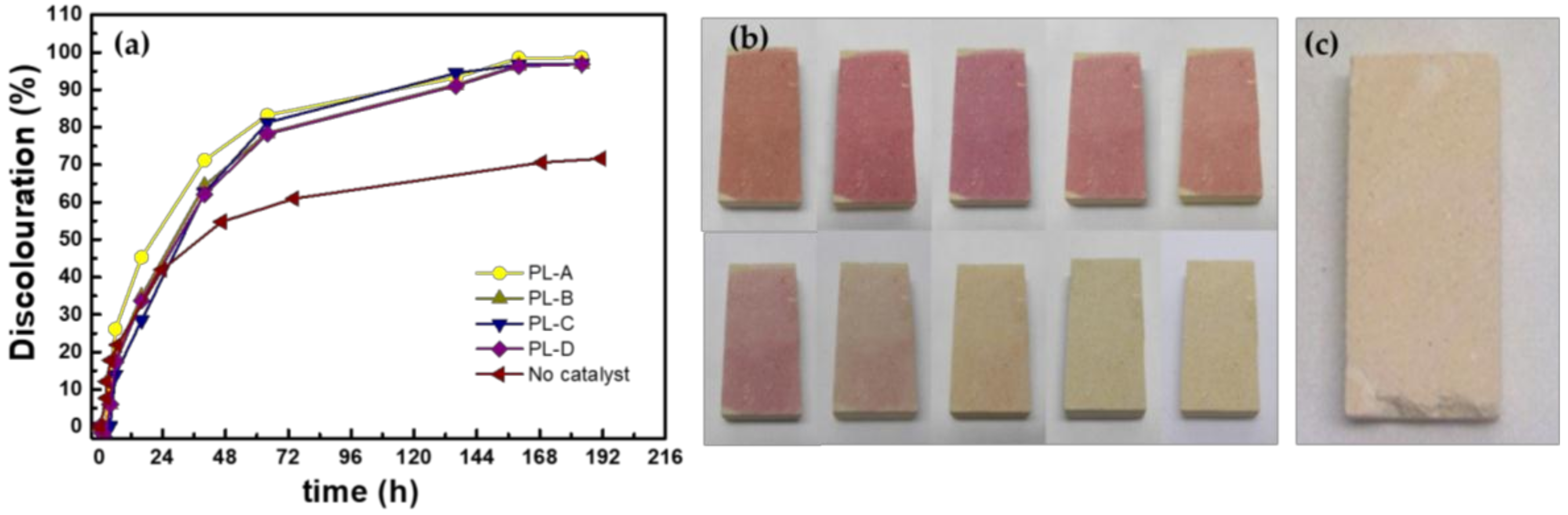
2.7.3. Colour Measurement

The measure of the colour change was performed with a Minolta CR 300 Chroma Meter reflectance colorimeter on the specimens measuring 5 × 1 × 5 cm3. The chromatic variation due to the application of catalyst was measured in the CIELab space and expressed as [39]
Δ E * = ( Δ L * ) 2 + ( Δ a * ) 2 + ( Δ b * ) 2
where ∆L* represents the change in brightness; ∆a* and ∆b* represent the changes in hue.

2.7.4. Water Absorption Test

To evaluate the water absorption, the contact-sponge test was carried out on the samples 5 × 2 × 5 cm3 in dimension [40].
According to the Italian standard [40], a Petri dish, 3.5 cm in diameter, containing a disc-shaped sponge (area of 9.29 cm2) soaked with deionized water was manually pressed against the stone surface for 1 min. The maximum pressure, restricted by the contact between the dish’s borders and the surface, was applied. In this way, the whole surface of the sponge touched the stone, since the wet sponge was about 1 mm thicker than the Petri dish. The Petri dish and the sponge inside were weighted immediately after both the addition of water and the contact with the surfaces under investigation. The lid on the Petri dish avoided sponge drying during the weight measurements.
Preliminary experiments were carried out to establish the volume of water appropriate for the test. Water dripped from the sponge pressed against the treated surfaces when more than 0.50 mL was used. This volume, thus, was chosen for all the tests. Water absorption was calculated as
W A = m i m f A t
where mi is the initial weight of the sponge soaked with water, mf is the weight of the sponge after the contact, A is the sponge area and t is the contact time.
The reported data are results of tests performed on the same samples before and after the treatments.

2.7.5. Water Vapour Permeability Test

The water vapour permeability is defined as the mass of water vapour transmitted through a sample per area unit in a time unit, under defined conditions, and describes the ability of a material to allow water vapour passing through. The permeability to water vapour was evaluated on the PL samples measuring 5 × 1 × 5 cm3, following the procedure described in [41].
The measurements were carried out on the untreated samples and repeated on the same samples after the treatment. The following equation was used to calculate the water vapour permeability:
WVP = Δ M ( t × A )
where ∆M is weight change in the steady state (expressed in g), A is the exposed area to water vapour (in m2) and t is the unit time (24 h). The exposed area was 0.001611 m2. In all the cases, the used ∆M was the average of three consequent values of the daily difference in weight [41].

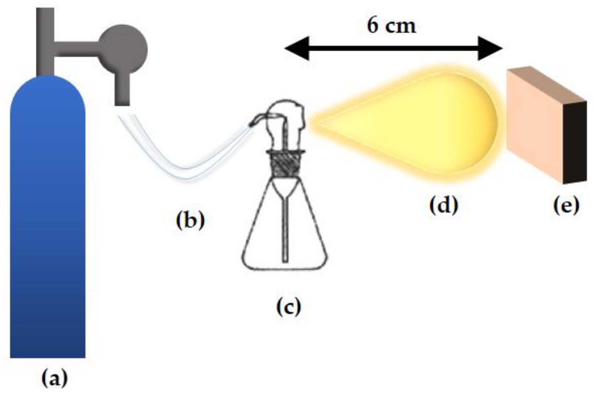
2.8. Photocatalytic Activity of Ti

O2 NR Treated Stone Samples
Photocatalytic activity of TiO2 NR coatings sprayed on PL substrates with dimensions of 5 × 1 × 2 cm3 (l, d, h) was evaluated as a function of the spraying time. The experiments were carried out under sunlight in outdoor weather conditions. The Methyl Red (MR) dye was selected as the model molecule for organic pollutants, a 3.5 × 10⁻³ M isopropanol solution was cast on the stone samples so that 9.4 × 10⁻⁹ mg·cm–2 MR was deposited. Control experiments were performed by exposing the untreated stone covered with the same amount of MR.
Samples were exposed outdoor for one week. During the experiment, the samples experience temperatures ranging between 23 and 27 °C and the relative humidity was 60%. The discolouration of the MR applied onto the specimens was monitored. The reflectance spectra at scheduled time intervals was recorded and the decrease of the absorption peak of the dye at 560 nm was measured by using the spectra recorded from the same specimens before staining with MR as a reference for the baseline. Reflectance spectra were carefully recorded on the same spot. The resulting data are expressed as a discolouration percentage of a function of exposure time, according to the equation:
% d e c o l o u r a t i o n = ( A 0 A t A 0 ) · 100
where A0 is the initial absorption value and At is the absorption at a specific time interval. Experimental results were reported as the mean value ± standard deviation of two replicates.
The stability of the coating was assessed by repeating the photocatalysis experiment 8 times under the same experimental conditions applied for the outdoor experiments, using, instead, a solar light simulator as a light source. In particular, the stone was stained with an MR solution, irradiated for 72 h with the solar light simulator and the reflectance measurement was performed in order to monitor the discolouration. In the subsequent cycle, the same stone was stained again before the subsequent irradiation cycle and the respective reflectance measurement. Such an approach allowed us to get insight into the reliability of the photocatalytic performance of the TiO2NRs-based coating upon a prolonged use. The experimental data are reported as a discolouration percentage measured after 72 h of exposure. The solar simulator is a Xenon lamp 150W, (Oriel Instruments Newport, CA, USA) with an irradiance of 1.48 mWcm–2 (1.48 SUN) measured at the distance where samples were placed during illumination (12 cm).

3. Results and Discussion

3.1. Photocatalyst Characterization

The synthesis of TiO2 NRs was carried out by following a “hot injection” method. The anisotropic growth of TiO2 NRs is promoted by the hydrolysis of titanium isopropoxide (TTIP) catalysed by trimethylamino-N-oxidedehydrate (TMAO) in the presence of oleic acid (OLEA) as a coordinating solvent. The TiO2 NRs synthesis occurs at relatively low-temperature values (80–100 °C) under nitrogen overpressure. The TMAO was previously dissolved in water before the injection in the reaction mixture containing the TTIP at 80–100 °C. The direct injection of an excess of water promotes the fast hydrolysis of the TTIP-OLEA complexes (oxocarboxyalkoxide). This step is kinetically driven because the TTIP-OLEA complexes display a potential “anisotropic reactivity” due to the sterically limited exposure of -OR moieties towards water. As a consequence, the excess of water promotes the anisotropic grow of TiO2 NRs along a direction with less steric hindrance [37].
After the synthesis, TiO2 NRs were carefully purified in order to remove the excess of OLEA uncoordinated to the TiO2 NR surface by repeating 8 consecutive washing cycles in n-hexane. The morphological investigation, carried out by TEM microscopy, clearly showed the presence of rod-shaped particles with an average length of 18 nm and an average thickness of 3 nm (Figure 1A).
The X-ray analysis in Figure 1B reported the diffraction lines associated with the presence of anatase phase.
The XRD profile of TiO2 NRs, showed the characteristic line broadening of diffraction peaks that point out the occurrence of a nanosized crystalline domain. Remarkably, with respect to the standard diffraction pattern of anatase phase (panel b, Figure 1B), the reflex at 2θ = 37.86° corresponding to the <004> plane is higher and sharper respect to the reflex at 2θ = 48.06°, 2θ = 55.09°, and 2θ = 70.32°, corresponding to the <200>, <211>, and <220> planes of the anatase phase respectively. Such features indicate the occurrence of the TiO2 nanocrystals anisotropic growth along the c-axis of the anatase lattice, thus suggesting the formation of rodlike nanocrystals [15,37]. Further, the XRD-pattern showed two additional signals at 2θ = 30° and 2θ = 33°. The latter correspond to the reflections <121> and <200> respectively of the brookite phase, very common for nanocrystalline TiO2.
An appropriate solvent selection is essential in order to obtain uniform and reproducible photocatalytic coatings. A suitable solvent needs to dissolve a proper amount of TiO2 NRs and concomitantly ensure a stable and clear dispersion of TiO2 NRs to prevent the formation of nanocrystal aggregates in the solvent dispersion and, consequently onto the substrate once deposited. Moreover, the solvent should have an appropriate vapour pressure and evaporation point as well as an adequate, sufficiently low boiling point to obtain a suitable aerosol and rapidly evaporate once sprayed on the surface in order to result in a uniform deposit.
Therefore, in order to perform such a selection, knowledge on the surface chemistry of TiO2 NRs is required. FT-IR-ATR analysis was performed and the results are reported in Figure 2. The spectrum recorded on a TiO2 NRs sample in ATR mode shows two peaks at 2923 cm–1 and 2854 cm–1 that can be assigned respectively to the antisymmetric and symmetric stretching of olefinic CH, while the shoulder at 2960 cm–1 can be associated to the antisymmetric stretching of CH3. The lack of the typical signal of carbonyl group stretching between 1760 and 1765 cm–1, indicates its involvement in the formation of a chelating bidentate complex with the Ti sites at the surface of TiO2, as confirmed by the presence of the two absorption peaks at 1527 cm–1 and 1463 cm–1 associated with the complexes of the COO group with Ti centres [42], ultimately demonstrating the coordination of the OLEA to the surface of TiO2 NRs through the carbonyl group. Therefore, the exposed hydrophobic chain of the OLEA imparts colloidal stability in the organic solvent with a low polarity to the NRs [37]. In summary, the OLEA molecules play the twofold role of reaction solvent and stabilizing agent of TiO2 NRs in organic solvents with low polarity. Thus, chloroform and n-heptane were selected as suitable solvents complying with the reported requirements in order to preliminarily investigate the effect of solvent and spraying time through the morphological and textural characteristics of the film obtained by the depositing dispersion of TiO2 NRs onto silicon chips (1 cm × 1 cm). Thus, we identified the most suited spray coating conditions

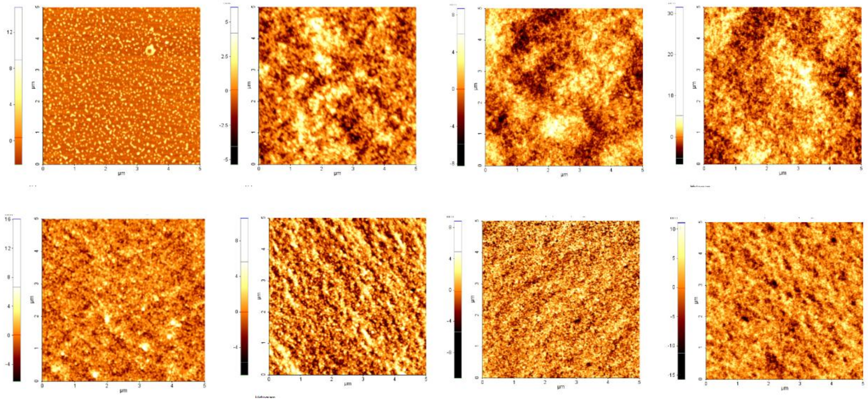
3.2. Optimization of the Deposition Conditions of TiO2NRs onto a Model Substrate

The TiO2 NRs dispersion was sprayed by using a system (Figure 3) consisting of a nebulizer (c) containing the TiO2 NRs dispersion, through which pure nitrogen (a) from the cylinder passes through, generating the TiO2 NRs dispersion aerosol (d). The TiO2 NRs dispersion aerosol is sprayed on the whole surface of the substrate (e), which is positioned at a defined distance from the nebulizer.
For the preliminary selection of the solvent for the TiO2 NRs to be applied onto PL specimens, silicon chips were sprayed with the TiO2 NRs chloroform and n-heptane dispersions (0.02 M in Ti), respectively, by varying the application time (Table 1). The chloroform dispersion of the TiO2 NRs was prepared by simple dilution from the as-synthesized dispersion of TiO2 NRs. The dispersion of TiO2 NRs in n-heptane was prepared by isolating a defined amount of TiO2 NRs by centrifugation from the as-synthesized chloroform solution and subsequently adding a volume of n-heptane suitable to obtain a 0.02 M Ti dispersion. Both the dispersions were found stable and optically clear. In order to assess reproducibility, three silicon substrates were prepared for each experimental condition listed in Table 1.
SEM investigation was preliminarily performed on these model samples in order to evaluate the effects of solvent and spraying time on the morphology of the obtained coatings.
Figure 4 reports the SEM micrographs recorded from the whole set of samples sprays coated with the TiO2 chloroform dispersion by exploiting the in-lens detector (the EDS spectrum is reported in Figure S1, Supplementary Material). The low magnification micrographs (Figure 4a,c,e,g) show circular patterns with a size in the range between 24 and 360 µm in diameter. Notably, the rim of these rings presents an intense contrast with respect to the inner region. In particular, most of the TiO2 NRs accumulate at the edge of such rings, possibly generated upon the landing of the aerosol droplets onto the substrate.
In addition, along the patterns, it is possible to notice smaller rings that result through the formation of TiO2 aggregates of about 200 nm size left upon solvent evaporation.
Such features can be safely ascribed to coffee-ring patterns originating from the capillary flow induced by the differential evaporation rates across a drop of solution onto a substrate: liquid evaporating from the edge is replenished by liquid from the interior, resulting in a flow towards the edge that can carry the dispersed TiO2 NRs to the border.
These structures are evident in the high magnification micrographs and in particular in Figure 4d,f,h, where a detail of the ring pattern highlights the presence of dense aggregates of TiO2 NRs. Further, the micrographs show aggregates of TiO2 NRs in the central region of the patterns. Such a morphology can be ascribable to the anisotropy of TiO2 NRs, which experience high capillary forces of attraction, resulting in a deformation of the pattern surface at the solid-air interface with a consequent uneven solvent evaporation that consequently affects the morphology of the final NRs’ deposit [43]. Remarkably, in the sample A-ch prepared by spraying TiO2 NRs for 1 min (Figure 4a,b) TiO2 NRs are detectable mainly at the border of the patterns, and the central area of the rings appears partially empty with circular patterns formed by TiO2 NRs aggregates, as displayed in Figure 4b. Therefore, TiO2 NRs chloroform dispersion, once sprayed for 1 min, results in a very irregular distribution of the NPs onto the substrate.
Circular patterns in the size range between 70 and 360 µm are also visible for the TiO2 NRs film deposited from the sprayed n-heptane dispersion onto the silicon substrate (Figure 5a,c,e,g). Interestingly, here the rims of the circles present an intense contrast, and the patterns are larger in size with an irregular shape. This evidence suggests that TiO2 NRs have a tendency to a more uniform coverage of the silicon substrate [43]. Indeed, the corresponding high magnification micrograph, in Figure 5b,d,f,h clearly show the presence of TiO2 NRs, distributed on the silicon substrate irrespectively of the spraying time. These pieces of evidence can be ascribed to the effect of the volatility of the two solvents with different boiling points on the droplet formation and, consequently, on the patterns resulting by solvent evaporation. When TiO2 NRs are dispersed in n-heptane, the solvent evaporation is slower than in the case of chloroform dispersion, since the relative evaporation rate is 3.3 [44] (considering 1 to be the value for the butyl acetate evaporation rate) for n-heptane, while it is 11.6 for chloroform [45]. Therefore, TiO2 NRs, have enough time, during the solvent evaporation, to aggregate at the solid-liquid interface due to capillary interactions, finally resulting in a uniform substrate coverage. Further, the hydrodynamic forces driving the particles towards the edge of the pattern during the evaporation were demonstrated to decrease as the pattern size increases [39].
The n-heptane dispersions resulted in the average size of the patterns being larger compared to those obtained from chloroform dispersion. Therefore TiO2 NRs, rather than accumulating at the edge of the drying drop, tend to distribute in the area inside the pattern.
In order to assess the influence of the solvent on the local topography of TiO2 NRs based coatings on the silicon substrates, AFM measurements were performed. According to Figure 6, the spray coating technique was allowed to entirely cover the surface of the silicon chip with TiO2 NRs, irrespectively on the solvent. The exception of sample A-Ch, however, showed uncovered areas, probably because the application time was too short. Such a result is consistent with the pattern morphology observed in Figure 4a, showing the central area of the ring, which appears to be empty. Figure 6 shows the morphology of the investigated samples. In particular, consistently with the roughness values (Rq) reported in Table 2, a general increase of the roughness as the spraying time increases can be observed. This evidence can be explained considering that with a longer spraying time more material is brought to the surface, generating, upon drying, multiple disordered layers of aggregates of NCs, having different sizes and, hence, different thickness layers, and finally, resulting into an increase of the roughness of the surface.
In summary, based on the preliminary SEM and AFM characterizations carried out on silicon, n-heptane was selected as the most suitable solvent for spray coating the TiO2 NRs dispersion onto the PL. Remarkably, the n-heptane dispersion results in a distribution of TiO2 NRs on silicon is present even more than that observed from the chloroform dispersion, overall limiting the occurrence of aggregates and cracks that are detrimental for the photocatalytic activity of the final TiO2 NRs’ treated surface. Moreover, compared to chloroform, higher roughness values were recorded for the surfaces treated with the n-heptane dispersion of TiO2 NRs, whilst maintaining a fixed spraying time. Such a result could be advantageous for the photocatalytic process as it provides a higher amount of surface sites available for adsorption and photocatalytic events.

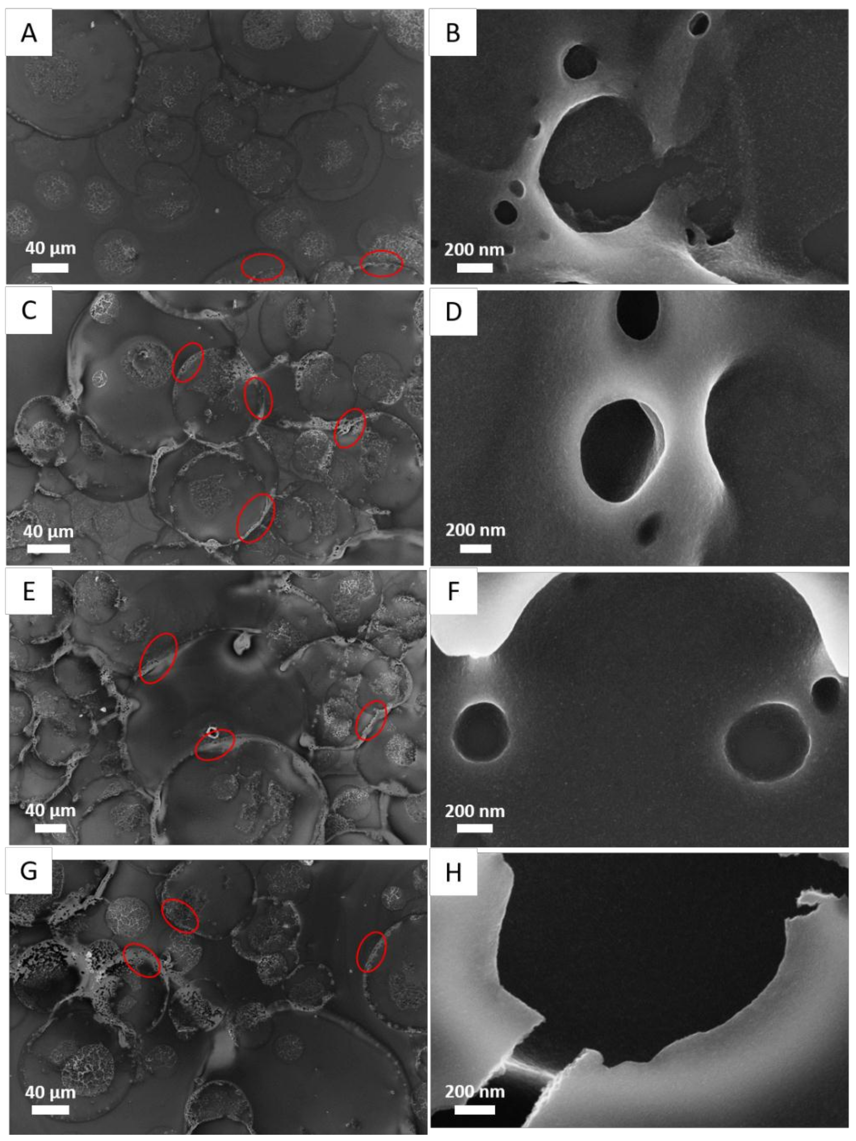
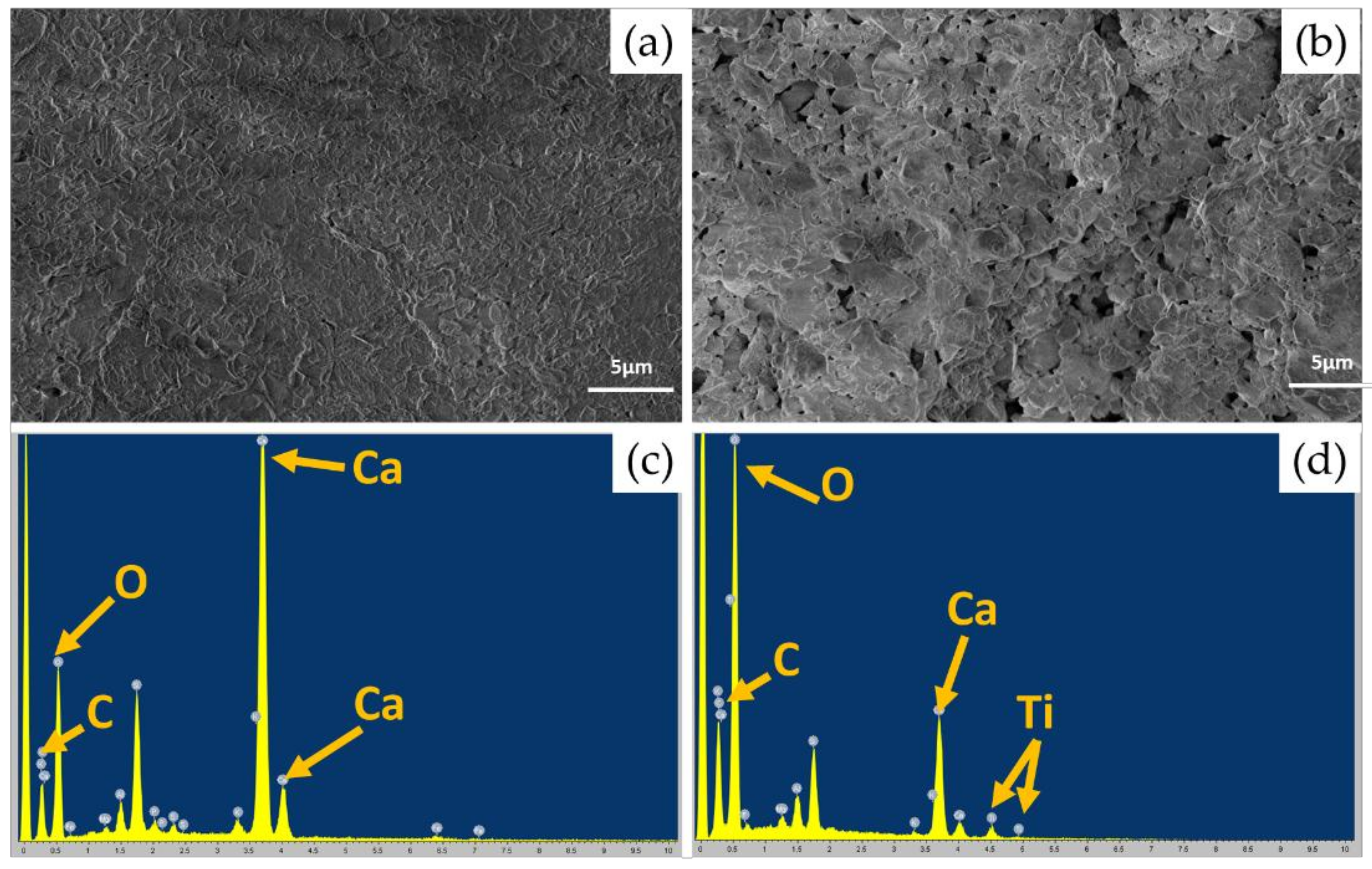
3.3. Deposition of TiO2 NRs on Lecce Stone

TiO2 NRs were applied by spray coating an NP n-heptane dispersion on PL specimens, by using the set up described in Figure 3 following the same protocol and the same application time adopted for the deposition on silicon substrates, as reported in Table 3. In particular, a 0.02 M n-heptane dispersion TiO2 NRs was sprayed onto 8 different PL specimens, 4 having a size of 5 × 1 × 5 cm3 (l, d, h) for the chemical-physical characterization and 4 having a size of 5 × 1 × 2 cm3 (l, d, h) for the photocatalysis experiment. The amount of TiO2 NRs deposited by spray coating was not determined, as it was below the detection limit of the analytical balance (0.1 mg). Diffuse reflectance spectroscopy measurements were performed on the whole set of samples and the recorded reflectance spectra (Figure 7) clearly show an increasing absorption below 400 nm. Indeed, the occurrence of an increase of the absorption intensity values, for wavelengths below 400 nm, is associated with the indirectly allowed transition of TiO2 NCs, as the TiO2 is an indirect semiconductor [30,46]. Notably, the signal intensity was higher for the PL-C and PL-D samples obtained by spraying the material for 2 min and for 2 min 30 s, respectively.
The effect of the surface treatment on colour variation, wettability, and water transfer properties was investigated. The preservation of the colour of the stone upon surface treatment is essential in order not to affect the aesthetics of a stone-built structure.
Colour measurements were carried out on the surface of the treated PL samples as a function of the spraying time used to apply the TiO2 dispersion, and Table 3 reports the values of the colour variation, ΔE*. A negligible colour variation was observed for the A and B samples, sprayed for 1 and 1 min 30 s, respectively. A higher ΔE* value (1.81) was measured for the C sample, although not significantly affecting the visual appearance of the treated stone. ΔE* increased to 3.33 for the D sample, sprayed for 2 min 30 s, reasonably due to the higher amount of deposited material, resulting in a thicker coating. However, in this case, the colour change stays below the threshold values fully acceptable according to the values typically reported for conservation purposes (ΔE < 5) [11].
The hydrophobic character of the applied treatment was assessed, performed after 20 days from the preparations by the measuring contact angle onto the treated samples while the water absorption properties by using of the contact sponge test described in Section 2.7.5. For the untreated samples, wettability was very high and a quick absorption of water droplets prevented the measurement of the contact angle. After the coating application, the contact angle value ranged from 130° to 136°, hence, wettability strongly decreased, irrespectively of the spraying time (Table 3), thus, proving the hydrophobic character of the surface of all the treated samples. Very close contact angle values were measured, especially in the case of the PL-C, PL-B and PL-D samples. The slightly lower value along with the higher dispersion measured for the PL-A samples could arise from a lower uniformity of the coatings obtained at the lowest spraying time. Similarly, a significant reduction of the capillary absorption ability was measured by the contact sponge test on the differently treated stone samples, as reported in Table 4. This method gives information about the reduction of the water absorption of the samples for short times of contact with water. Nonetheless, water absorption measured with the contact sponge test is comparable to the results obtained by the capillary rise method. The relevant literature reports no significant differences between the results of the two methods at similar (short) contact times and similar precision and sensitivity [47]. Both methods measure the water absorption in the outmost superficial layer, which, in the conservation/restoration field, is the most important because the deterioration processes, either of treated or untreated materials, take place mainly at the stone surface.
The dispersion of the water absorption values before coating was extremely high between the PL samples from A to D, and notably higher for PL-D and PL-C, thus, denoting a high heterogeneity of the inherent physical stone characteristics. After coating, the water absorption values strongly reduced, except for PL-A, where they slightly increased. The hydrophobic behaviour can be safely ascribed to the presence of OLEA on the surface of the TiO2 NRs. As demonstrated by the FTIR-ATR spectra (Figure 2), the OLEA anchors to the surface of the TiO2 by a bi-dentate bond involving the carbonyl moiety, while the OLEA hydrophobic chain points outward, giving a hydrophobic character to the surface of the TiO2 NRs and, accordingly, to the nanostructure treated stone surface [30]. Additionally, the water absorption strongly reduced in the treated stone samples, with values slightly increasing as the spraying time increases. Therefore, the TiO2NRs based treatment results particularly amenable for application in the field of conservation, being a hydrophobic coating able to reduce salt formation, that is detrimental as it induces mechanical strain and deterioration of the stone surfaces [15].
While reducing the penetration of water inside the stone, an ideal surface treatment should not turn in any significant variation of the water vapour transfer within the stone in order to avoid a barrier effect of the treatment against water entrapped in the porous structure and migrating outwards. As it is shown in Table 4, a decrease in water vapour permeability (ΔWVP) was observed in the cases of the A, B and D coated samples. On the contrary, an increase in the same parameter was observed in the case of the C coating. Permeability variations showed no relations with the spraying time. The highest reduction of the WVP value was recorded for the samples D and A, which were treated for the shortest and the longest spraying time, and reported a reduction of 19% and 23%, respectively. Nonetheless, the recorded variations in the WVP were found still compatible with the original permeability properties of the stone.
Since water permeability is correlated with the stone porosity, the reduction observed for the PL-A, PL-B, and PL-D specimens suggest that the coating application may have affected the porosity features of the stone in the proximity of the surface by reducing pore dimensions due to the penetration of the nanoparticles therein. Permeability variations did not show relations with spraying time. Except for PL-C, the entities of reduction were proportional to the permeability of the samples before the coating, being higher for the more permeable ones. These results suggest that other factors, such as the inherent microstructure features drive the penetration of the coating product inside the stone and their variations between different specimens could have determined the different responses recorded in terms of water vapour permeability. On the contrary, a permeability increase took place for the PL-C specimens, which showed the lowest permeability in the absence of the coating. Permeability may also increase, as reported for the PL-C specimen. Such behaviour is reported in the literature for hydrophobic thin coatings on marbles [48] and membranes [49] and it can be associated to a lower extent of condensation phenomena on the hydrophobic walls of the pores. That, however, is reported to occur mainly when the treatment on the stone does not result in a pore size reduction. Therefore, the result obtained for PL-C could arise from a significantly different pore structure of these samples compared to the other ones, resulting in different interactions with coating products and subsequent water vapour transfer. Notably, the reported water vapour permeability percentage of variation, for the PL-A, PL-B and PL-D specimens falls in the range reported as acceptable of hydrophobic products applied to monument surfaces [14].
The presence of TiO2 NRs based coating on the PL surface was assessed by SEM microscopy combined with EDS microanalysis, carried out on the PL D specimen as representative of the whole set. Figure 8 aims at comparing the surface morphology of the untreated PL stone (a) with the sample PL D (b). For the treated sample, the TiO2 NRs-based coating induced a modification of PL morphology, which cannot be detected by the naked eye. In particular, in the PL D sample, the coating resulted in grainy and densely packed aggregates forming a uniform crack-free coating on the stone surface. The amount of TiO2 NRs sprayed for 2 min 30 s (the D specimen) is adequate to provide a continuous coverage conformal to the morphology of the stone underneath. Such an observation is evident in the light of the striking differences between the treated and the untreated sample in terms of morphology and chemical composition of the surface as reported in Figure 8c,d, respectively [50]. Indeed, the respective EDS spectra reported in Figure 8c,d confirmed the presence of the TiO2 NRs based coating not only by the occurrence of typical additional peaks of Ti (Kα = 4; 508 kev) but also by the increase O/Ca ratio (Figure 8d), compared to the untreated stone (Figure 8c), in accordance with the DRS analysis.

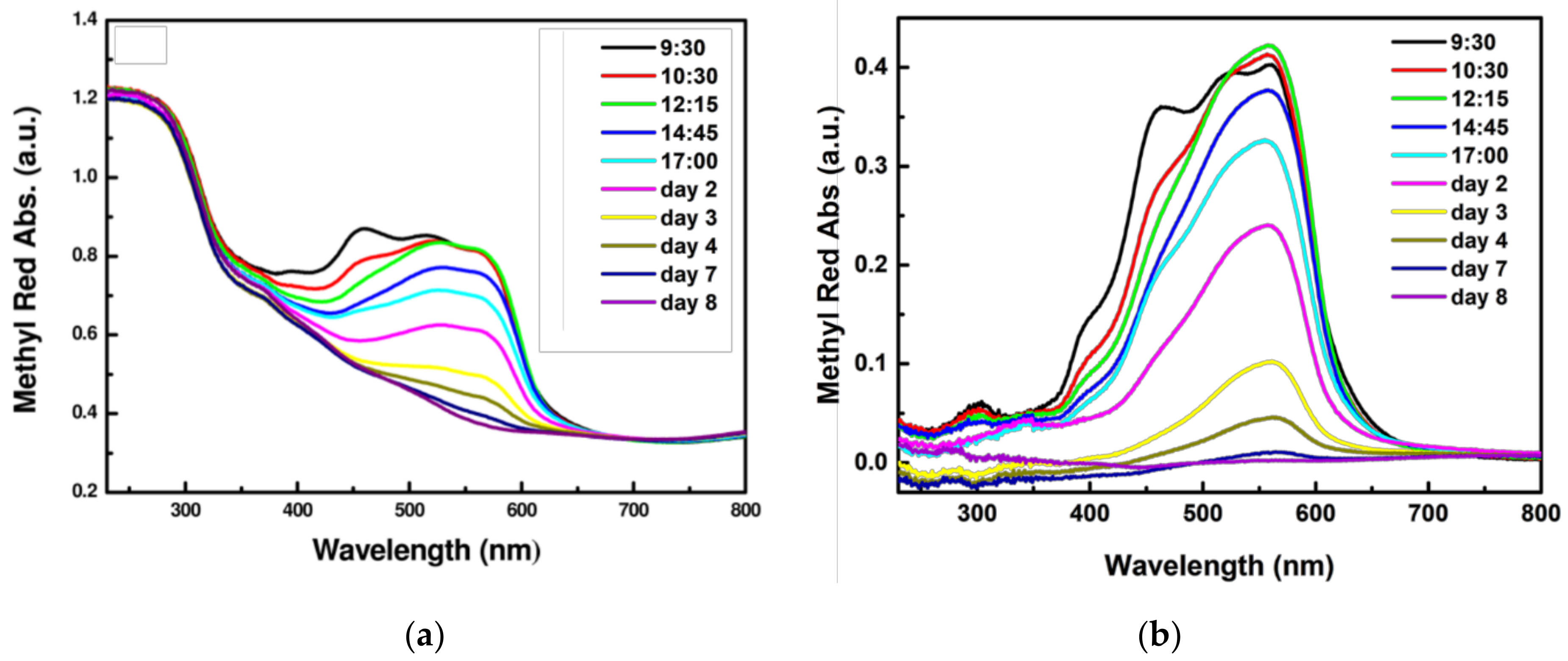
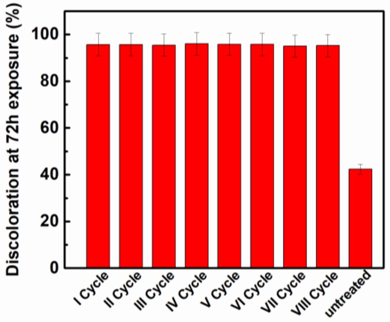
3.4. Photocatalytic Activity

The PL samples spray coated with the TiO2 NRs were stained with an azo dye, Methyl Red (MR), and exposed outdoors in order to investigate the photocatalytic self-cleaning activity in real conditions as a function of spraying time. The MR has been selected as a model compound for organic contaminants for the photocatalytic experiments as widely used to test the photocatalytic activity of different materials, including functional coatings for stone [30,50] because its spectroscopic behaviour and its photodegradation mechanism have been comprehensively investigated and provide reliable information on the photo-reaction course [50,51,52]. Once the TiO2 NRs were sprayed onto the PL surface after the complete solvent evaporation on the PL stone surface, 0.1 mL of a 3.5 × 10⁻³ M MR isopropanol solution was cast, resulting in an intense red stain uniformly distributed on the stone surface.
The stained stones were exposed outdoor for a week and the stain discolouration on the stone was monitored by reflectance spectroscopy following the decrease of intensity the absorption peak of MR at 560 nm. Experimental data, reported as the discolouration percentage as a function of the total exposure time (also including the night hours), pointed out that all the investigated samples showed photocatalytic activity. Indeed, the 50% discolouration level was reached after 48 h of outdoor exposure and after 160 h, the discolouration reached 100% for all investigated TiO2 NR coated samples (Figure 9a).
When the UV fraction of solar spectrum irradiates TiO2 NRs, the photogenerated e- and h+ can migrate to the TiO2 NRs surface where they react with atmospheric O2 and H2O molecules (aqueous vapour), respectively. In particular, the photogenerated e- can reduce the O2 generating O2, while h+ reacts with H2O, giving rise to the formation of OH. Both O2 and OH are Reactive Oxygen Species (ROS) responsible of MR discolouration. In addition, the direct reaction of MR with e and h+ can be taken into account. The high photocatalytic performance of the TiO2 NRs based coating is safely accounted for by the structure and morphology of the TiO2 NRs, which has been demonstrated to efficiently cover the PL surface, and to convey photocatalytic activity even when a low amount of photocatalyst is deposited by spray coating. Despite the wide band gap of TiO2, presenting an absorption edge at 3.2 eV [53], TiO2 NRs were photoactive under visible light irradiation. It can be proposed that the UV fraction of the solar spectrum is sufficient to induce the e-/h+ generation events. Further, because of the peculiar geometry of TiO2 NRs, the e-/h+ recombination events are limited, resulting in efficient photocatalytic activity [54]. The high surface area of TiO2 NRs of 240 ± 5m2/g [51] is an additional parameter that accounts for its photocatalytic efficiency that, according to the reported results, is independent of the spraying time, and, hence, of the applied amount of materials. Therefore, 1 min spraying time was revealed to be sufficient to form a photoactive film able to efficiently remove the MR stain, limiting the amount of used functional nanomaterial.
The issue of the stability of the TiO2 NR film obtained by spray coating was also addressed by examining the signal associated with TiO2 NRs in the reflectance spectrum of the sample PL-D during the course of photocatalysis experiment, as reported in Figure 10. Both Figure 10a,b refer to the same experiment and report the reflectance spectra and the corresponding absorption signal obtained upon conversion from the reflectance spectrum to the absorption spectrum, respectively, in order to clearly identify the typical absorption features of Methyl Red (MR) and to be able to follow its discolouration course. In particular, all the spectra of Figure 10a not only show the absorption features of MR, but also account for the typical absorption signal of the TiO2NRs below 400 nm. Therefore, in order to clearly identify these spectral features, the absorption spectrum of the untreated stone was used as the baseline for each spectrum of Figure 10a. That is, the absorption spectrum of the untreated stone was used as a reference and subtracted from each spectrum of the sample undergoing photocatalysis experiments in order to rule out the contribution of the bare PL. Similarly, Figure 10b reports the absorption spectra of the PL stone in the course of the photocatalysis experiment. In the latter case, the trace of the sample PL-D, before staining with MR, was subtracted from each absorption spectra in order to rule out any absorption contribution both from the bare PL and TiO2 NRs and, thus, allow us to specifically monitor the discolouration course of the MR. Indeed, as shown in Figure 10a, the reflectance spectrum of MR does not show any detectable signal in the spectral range below 350 nm. The reflectance spectrum recorded with the untreated stone as a reference clearly shows how the typical spectral feature of the TiO2 is retained during the solar light irradiation, thus suggesting that, despite the exposition to solar light and outdoor weather conditions, the TiO2 NRs coating deposited by spray coating on PL preserved its stability.
Figure 11 reports the experimental results related to the recycling experiments. Photocatalytic experiments were repeated by using a solar light simulator as a light source and by selecting the PL-D which showed the best photocatalytic performance in outdoor experiments. The discolouration value measured for an untreated PL specimen after 1 cycle was also reported for comparison. For each repetition, the PL-D sample stained with the MR solution was irradiated for 72 h with the solar light simulator. As a result, after each experiment, the discolouration percentage stayed at 95%, thus indicating the stability of the TiO2 NRs-based coating and its photocatalytic performance under the investigated experimental conditions.

4. Conclusions

This work investigated and optimized the experimental conditions suited to effectively applying rod-shaped TiO2 nanocrystals by spray coating, with the final goal to convey hydrophobic and photocatalytic properties to the surface of the Lecce stone.
TiO2 NRs, synthesized according to a colloidal protocol that allows us to achieve anisotropic nanoparticles with a peculiar surface chemistry featured by OLEA molecules coordinating with the TiO2 NRs surface, were dispersed in two different solvents, namely, the chloroform and the n-heptane, thus achieving stable dispersions suited to be sprayed on surfaces. The controlled and reproducible experimental conditions for spray coating were set up and investigated, exploiting silicon substrates as a model surface. The results of the SEM and AFM analysis allowed us to select n-hexane as the most suited solvent for depositing TiO2 NRs on surfaces by spray coating. These coatings were more uniform, without cracks, and had a higher roughness compared to the coatings obtained from the chloroform dispersion. Therefore, the TiO2 NRs n-heptane dispersion was sprayed onto the PL samples, testing the effect of the spraying time, resulting in the hydrophobic properties and crack-free coatings that did not affect the aesthetical features of the PL, as well its water vapour permeability, thus resulting in being compatible with the original characteristics of the stone. Remarkably, the photocatalytic activity was found not to be affected by the spray coating time, thus allowing us to optimize the amount of applied functional nanomaterial, and to limit the exposure of the operator to the solvent vapours. The D coatings exhibit photocatalytic activity under solar light irradiation in outdoor conditions and even upon repeated experiments, thus, indicating its stability and effectiveness in time.
The overall results point out that a convenient spraying time can be used to successfully and cost-effectively treat stone samples, obtaining a photoactive and hydrophobic coating. Therefore, from this perspective, although relevant issues including the long-term stability, the photocatalytic efficiency with respect to specific real pollutants, and different stony substrates need to be carefully accounted and solved, spray coating TiO2 NRs n-heptane dispersion holds a significant promise for its real application onto buildings and monuments.

Supplementary Materials

The following are available online at https://www.mdpi.com/2079-6412/8/10/356/s1, Figure S1: EDS spectrum of TiO2 NRs deposited by spray coating on silicon substrates from the chloroform solution 0.02 M with an application time of 1 min (sample A-ch). The spectrum shows the presence of Ti, C and O. The SEM measurements were performed with an accelerating voltage of 1 kV, a working distance of 3.7 mm and an aperture size of 20 µm.

Author Contributions

F.P., A.P., M.L., A.C., M.L.C., R.C. conceived and designed the experiments; F.P., A.P., M.L., M.M., A.T. performed the experiments; F.P., A.T., A.P., M.L., A.C., M.L.C. and R.C. analyzed the data; F.P., R.C., M.L.C, M.L. and A.C. wrote the paper.

Funding

This work was partially supported by the EC-funded project Innovaconcrete (H2020; Grant No. 760858), by the Italian Regional Network of Laboratories “Sens&Micro” and “VALBIOR” projects (POFESR 2007-2013) and by Apulia Region funded FontanApulia (WOBV6K5).

Conflicts of Interest

The authors declare no conflict of interest. The founding sponsors had no role in the design of the study; in the collection, analyses, or interpretation of data; in the writing of the manuscript, and in the decision to publish the results.

References

  1. Sang, L.; Zhao, Y.; Burda, C. TiO2 nanoparticles as functional building blocks. Chem. Rev. 2014, 114, 9283–9318. [Google Scholar] [CrossRef] [PubMed]
  2. Schneider, J.; Matsuoka, M.; Takeuchi, M.; Zhang, J.; Horiuchi, Y.; Anpo, M.; Bahnemann, D.W. Understanding TiO2 photocatalysis: Mechanisms and materials. Chem. Rev. 2014, 114, 9919–9986. [Google Scholar] [CrossRef] [PubMed]
  3. Banerjee, S.; Dionysiou, D.D.; Pillai, S.C. Self-cleaning applications of TiO2 by photo-induced hydrophilicity and photocatalysis. Appl. Catal. B Environ. 2015, 176–177, 396–428. [Google Scholar] [CrossRef]
  4. Herrmann, J.-M. Heterogeneous photocatalysis: Fundamentals and applications to the removal of various types of aqueous pollutants. Catal. Today 1999, 53, 115–129. [Google Scholar] [CrossRef]
  5. Petronella, F.; Truppi, A.; Ingrosso, C.; Placido, T.; Striccoli, M.; Curri, M.L.; Agostiano, A.; Comparelli, R. Nanocomposite materials for photocatalytic degradation of pollutants. Catal. Today 2017, 281, 85–100. [Google Scholar] [CrossRef]
  6. Lai, Y.; Huang, J.; Cui, Z.; Ge, M.; Zhang, K.-Q.; Chen, Z.; Chi, L. Recent advances in TiO2-based nanostructured surfaces with controllable wettability and adhesion. Small 2016, 12, 2203–2224. [Google Scholar] [CrossRef] [PubMed]
  7. Varshney, G.; Kanel, S.R.; Kempisty, D.M.; Varshney, V.; Agrawal, A.; Sahle-Demessie, E.; Varma, R.S.; Nadagouda, M.N. Nanoscale TiO2 films and their application in remediation of organic pollutants. Coord. Chem. Rev. 2016, 306, 43–64. [Google Scholar] [CrossRef]
  8. Rtimi, S.; Giannakis, S.; Pulgarin, C. Self-sterilizing sputtered films for applications in hospital facilities. Molecules 2017, 22, 1074. [Google Scholar] [CrossRef] [PubMed]
  9. Salthammer, T.; Fuhrmann, F. Photocatalytic surface reactions on indoor wall paint. Environ. Sci. Technol. 2007, 41, 6573–6578. [Google Scholar] [CrossRef] [PubMed]
  10. Hernández Rodríguez, M.J.; Pulido Melián, E.; González Díaz, O.; Araña, J.; Macías, M.; González Orive, A.; Doña Rodríguez, J.M. Comparison of supported TiO2 catalysts in the photocatalytic degradation of NOx. J. Mol. Catal. A Chem. 2016, 413, 56–66. [Google Scholar] [CrossRef]
  11. Munafò, P.; Goffredo, G.B.; Quagliarini, E. TiO2-based nanocoatings for preserving architectural stone surfaces: An overview. Constr. Build. Mater. 2015, 84, 201–218. [Google Scholar] [CrossRef]
  12. Baglioni, P.; Carretti, E.; Chelazzi, D. Nanomaterials in art conservation. Nat. Nanotechnol. 2015, 10, 287. [Google Scholar] [CrossRef] [PubMed]
  13. Antizar-Ladislao, B.; Galil, N.I. Biofilm and colloidal biomass dynamics in a shallow sandy contaminated aquifer under in-situ remediation conditions. Int. Biodeterior. Biodegrad. 2010, 64, 331–338. [Google Scholar] [CrossRef]
  14. Kapridaki, C.; Maravelaki-Kalaitzaki, P. TiO2–SiO2–PDMS nano-composite hydrophobic coating with self-cleaning properties for marble protection. Prog. Org. Coat. 2013, 76, 400–410. [Google Scholar] [CrossRef]
  15. Cappelletti, G.; Fermo, P.; Camiloni, M. Smart hybrid coatings for natural stones conservation. Prog. Org. Coat. 2015, 78, 511–516. [Google Scholar] [CrossRef]
  16. Manoudis, P.N.; Karapanagiotis, I.; Tsakalof, A.; Zuburtikudis, I.; Kolinkeová, B.; Panayiotou, C. Superhydrophobic films for the protection of outdoor cultural heritage assets. Appl. Phys. A 2009, 97, 351–360. [Google Scholar] [CrossRef]
  17. La Russa, M.F.; Ruffolo, S.A.; Rovella, N.; Belfiore, C.M.; Palermo, A.M.; Guzzi, M.T.; Crisci, G.M. Multifunctional TiO2 coatings for cultural heritage. Prog. Org. Coat. 2012, 74, 186–191. [Google Scholar] [CrossRef]
  18. Kapridaki, C.; Pinho, L.; Mosquera, M.J.; Maravelaki-Kalaitzaki, P. Producing photoactive, transparent and hydrophobic SiO2-crystalline TiO2 nanocomposites at ambient conditions with application as self-cleaning coatings. Appl. Catal. B Environ. 2014, 156–157, 416–427. [Google Scholar] [CrossRef]
  19. Arturi, K.R.; Jepsen, H.; Callsen, J.N.; Søgaard, E.G.; Simonsen, M.E. Superhydrophilicity and durability of fluoropolymer-TiO2 coatings. Prog. Org. Coat. 2016, 90, 132–138. [Google Scholar] [CrossRef]
  20. Ingrosso, C.; Esposito Corcione, C.; Striani, R.; Comparelli, R.; Striccoli, M.; Agostiano, A.; Curri, M.L.; Frigione, M. UV-curable nanocomposite based on methacrylic-siloxane resin and surface-modified TiO2 nanocrystals. ACS Appl. Mater. Interfaces 2015, 7, 15494–15505. [Google Scholar] [CrossRef] [PubMed]
  21. Esposito Corcione, C.; Ingrosso, C.; Petronella, F.; Comparelli, R.; Striccoli, M.; Agostiano, A.; Frigione, M.; Curri, M.L. A designed UV–vis light curable coating nanocomposite based on colloidal TiO2 nrs in a hybrid resin for stone protection. Prog. Org. Coat. 2018, 122, 290–301. [Google Scholar] [CrossRef]
  22. Franzoni, E.; Fregni, A.; Gabrielli, R.; Graziani, G.; Sassoni, E. Compatibility of photocatalytic TiO2-based finishing for renders in architectural restoration: A preliminary study. Build. Environ. 2014, 80, 125–135. [Google Scholar] [CrossRef]
  23. Fonseca, A.J.; Pina, F.; Macedo, M.F.; Leal, N.; Romanowska-Deskins, A.; Laiz, L.; Gómez-Bolea, A.; Saiz-Jimenez, C. Anatase as an alternative application for preventing biodeterioration of mortars: Evaluation and comparison with other biocides. Int. Biodeterior. Biodegrad. 2010, 64, 388–396. [Google Scholar] [CrossRef] [Green Version]
  24. Gómez-Ortíz, N.; De la Rosa-García, S.; González-Gómez, W.; Soria-Castro, M.; Quintana, P.; Oskam, G.; Ortega-Morales, B. Antifungal coatings based on Ca(OH)2 mixed with ZnO/TiO2 nanomaterials for protection of limestone monuments. ACS Appl. Mater. Interfaces 2013, 5, 1556–1565. [Google Scholar] [CrossRef] [PubMed]
  25. Smits, M.; Chan, C.k.; Tytgat, T.; Craeye, B.; Costarramone, N.; Lacombe, S.; Lenaerts, S. Photocatalytic degradation of soot deposition: Self-cleaning effect on titanium dioxide coated cementitious materials. Chem. Eng. J. 2013, 222, 411–418. [Google Scholar] [CrossRef]
  26. Bergamonti, L.; Alfieri, I.; Lorenzi, A.; Predieri, G.; Barone, G.; Gemelli, G.; Mazzoleni, P.; Raneri, S.; Bersani, D.; Lottici, P.P. Nanocrystalline TiO2 coatings by sol–gel: Photocatalytic activity on Pietra di Noto biocalcarenite. J. Sol-Gel Sci. Technol. 2015, 75, 141–151. [Google Scholar] [CrossRef]
  27. Calia, A.; Lettieri, M.; Masieri, M.; Pal, S.; Licciulli, A.; Arima, V. Limestones coated with photocatalytic TiO2 to enhance building surface with self-cleaning and depolluting abilities. J. Clean. Product. 2017, 165, 1036–1047. [Google Scholar] [CrossRef]
  28. Quagliarini, E.; Bondioli, F.; Goffredo, G.B.; Licciulli, A.; Munafò, P. Self-cleaning materials on architectural heritage: Compatibility of photo-induced hydrophilicity of TiO2 coatings on stone surfaces. J. Cult. Herit. 2013, 14, 1–7. [Google Scholar] [CrossRef]
  29. Gherardi, F.; Colombo, A.; D'Arienza, M.; Di Credico, B.; Goidanich, S.; Morazzoni, F.; Simonutti, R.; Toniolo, L. Efficient self-cleaning treatments for built heritage based on highly photo-active and well-dispersible TiO2 nanocrystals. Microchem. J. 2016, 126, 54–62. [Google Scholar] [CrossRef]
  30. Petronella, F.; Pagliarulo, A.; Striccoli, M.; Calia, A.; Lettieri, M.; Colangiuli, D.; Curri, M.; Comparelli, R. Colloidal nanocrystalline semiconductor materials as photocatalysts for environmental protection of architectural stone. Crystals 2017, 7, 30. [Google Scholar] [CrossRef]
  31. Calia, A.; Lettieri, M.; Masieri, M. Durability assessment of nanostructured TiO2 coatings applied on limestones to enhance building surface with self-cleaning ability. Build. Environ. 2016, 110, 1–10. [Google Scholar] [CrossRef]
  32. Lorenzo Graziani, E.Q.; D’Orazio, M. Superfici autopulenti e biocide nel restauro archeologico di pietre e laterizi. Restauro Archeologico 2016, 25, 28–43. [Google Scholar]
  33. Esposito Corcione, C.; De Simone, N.; Santarelli, M.L.; Frigione, M. Protective properties and durability characteristics of experimental and commercial organic coatings for the preservation of porous stone. Prog. Org. Coat. 2017, 103, 193–203. [Google Scholar] [CrossRef]
  34. D’Arienzo, M.; Carbajo, J.; Bahamonde, A.; Crippa, M.; Polizzi, S.; Scotti, R.; Wahba, L.; Morazzoni, F. Photogenerated defects in shape-controlled TiO2 anatase nanocrystals: A probe to evaluate the role of crystal facets in photocatalytic processes. J. Am. Chem. Soc. 2011, 133, 17652–17661. [Google Scholar] [CrossRef] [PubMed]
  35. Fittipaldi, M.; Curri, M.L.; Comparelli, R.; Striccoli, M.; Agostiano, A.; Grassi, N.; Sangregorio, C.; Gatteschi, D. A multifrequency EPR study on organic-capped anatase TiO2 nanocrystals. J. Phys. Chem. C 2009, 113, 6221–6226. [Google Scholar] [CrossRef]
  36. Chen, X.; Mao, S.S. Titanium dioxide nanomaterials:  Synthesis, properties, modifications, and applications. Chem. Rev. 2007, 107, 2891–2959. [Google Scholar] [CrossRef] [PubMed]
  37. Cozzoli, P.D.; Kornowski, A.; Weller, H. Low-temperature synthesis of soluble and processable organic-capped anatase TiO2 nanorods. J. Am. Chem. Soc. 2003, 125, 14539–14548. [Google Scholar] [CrossRef] [PubMed]
  38. EN 15802 Conservation of Cultural Property—Test Methods—Determination of Static Contact Angle; CEN (European Committee for Standardization): Brussels, Belgium, 2010.
  39. EN 15886 Conservation of Cultural Property—Test Methods—Colour Measurement of Surfaces; CEN (European Committee for Standardization): Brussels, Belgium, 2010.
  40. UNI 11432 Cultural Heritage—Natural and Artificial Stone—Determination of the Water Absorption by Contact Sponge; Ente Italiano di Normazione: Milan, Italy, 2011. (In Italian)
  41. NORMAL Rec. 21/85 Permeabilità al vapor d’acqua Italy; C.I.R.: Rome, Italy, 1985. (In Italian) [Google Scholar]
  42. Chen, Y.; Kang, K.S.; Yoo, K.H.; Jyoti, N.; Kim, J. Cause of slow phase transformation of TiO2 nanorods. J. Phys. Chem. C 2009, 113, 19753–19755. [Google Scholar] [CrossRef]
  43. Kim, D.-O.; Pack, M.; Hu, H.; Kim, H.; Sun, Y. Deposition of colloidal drops containing ellipsoidal particles: Competition between capillary and hydrodynamic forces. Langmuir 2016, 32, 11899–11906. [Google Scholar] [CrossRef] [PubMed]
  44. Smallwood, I.M. Handbook of Organic Solvent Properties; Butterworth-Heinemann: Oxford, UK, 1996. [Google Scholar]
  45. Mackison, F.W.; Stricoff, R.S.; Partridge, L.J., Jr. Occupational Health Guidelines for Chemical Hazards; DHHS (NIOSH) Publication Number 81-123; The National Institute for Occupational Safety and Health (NIOSH): Atlanta, GA, USA, 1981. [Google Scholar]
  46. López, R.; Gómez, R. Band-gap energy estimation from diffuse reflectance measurements on sol–gel and commercial TiO2: A comparative study. J. Sol-Gel Sci. Technol. 2012, 61, 1–7. [Google Scholar] [CrossRef]
  47. Vandevoorde, D.; Pamplona, M.; Schalm, O.; Vanhellemont, Y.; Cnudde, V.; Verhaeven, E. Contact sponge method: Performance of a promising tool for measuring the initial water absorption. J. Cult. Herit. 2009, 10, 41–47. [Google Scholar] [CrossRef]
  48. Kronlund, D.; Bergbreiter, A.; Meierjohann, A.; Kronberg, L.; Lindén, M.; Grosso, D.; Smått, J.-H. Hydrophobization of marble pore surfaces using a total immersion treatment method—Product selection and optimization of concentration and treatment time. Prog. Org. Coat. 2015, 85, 159–167. [Google Scholar] [CrossRef]
  49. Dumée, L.; Germain, V.; Sears, K.; Schütz, J.; Finn, N.; Duke, M.; Cerneaux, S.; Cornu, D.; Gray, S. Enhanced durability and hydrophobicity of carbon nanotube bucky paper membranes in membrane distillation. J. Membr. Sci. 2011, 376, 241–246. [Google Scholar] [CrossRef]
  50. Licciulli, A.; Calia, A.; Lettieri, M.; Diso, D.; Masieri, M.; Franza, S.; Amadelli, R.; Casarano, G. Photocatalytic TiO2 coatings on limestone. J. Sol-Gel Sci. Technol. 2011, 60, 437–444. [Google Scholar] [CrossRef]
  51. Petronella, F.; Fanizza, E.; Mascolo, G.; Locaputo, V.; Bertinetti, L.; Martra, G.; Coluccia, S.; Agostiano, A.; Curri, M.L.; Comparelli, R. Photocatalytic activity of nanocomposite catalyst films based on nanocrystalline metal/semiconductors. J. Phys. Chem. C 2011, 115, 12033–12040. [Google Scholar] [CrossRef]
  52. Comparelli, R.; Fanizza, E.; Curri, M.L.; Cozzoli, P.D.; Mascolo, G.; Passino, R.; Agostiano, A. Photocatalytic degradation of azo dyes by organic-capped anatase TiO2 nanocrystals immobilized onto substrates. Appl. Catal. B Environ. 2005, 55, 81–91. [Google Scholar] [CrossRef]
  53. Fujishima, A.; Zhang, X.; Tryk, D.A. TiO2 photocatalysis and related surface phenomena. Surf. Sci. Rep. 2008, 63, 515–582. [Google Scholar] [CrossRef]
  54. Wu, H.B.; Hng, H.H.; Lou, X.W. Direct synthesis of anatase TiO2 nanowires with enhanced photocatalytic activity. Adv. Mater. 2012, 24, 2567–2571. [Google Scholar] [CrossRef] [PubMed]
Figure 1. (A) The TEM micrograph of an OLEA-Capped TiO2 NRs sample; (B) XRD experimental pattern of OLEA-Capped TiO2 NRs sample (a) and Bragg hkl reflection for anatase (b) and brookite (c) phase.
Coatings 08 00356 g001
Figure 2. The FT-IR-ATR spectrum of TiO2 NRs in the 4000–700 cm–1 region.
Coatings 08 00356 g002
Figure 3. The experimental set up for spray coating substrates (Silicon chips or Lecce stone specimens) with TiO2 NRs. A controlled amount of nitrogen was fluxed from the gas cylinder (a) to the nebulizer (c) through the rubber tube (b). The nebulizer contained the chloroform/n-heptane dispersion of TiO2 NRs, which was finally sprayed on the substrate (e) located at the distance of 6 cm from the nebulizer.
Coatings 08 00356 g003
Figure 4. The SEM micrographs of TiO2 NRs deposited by spray coating on silicon substrates from a chloroform solution of 0.02 M. The micrographs are low magnification (right column) and high magnification (left column) images respectively of coatings obtained with an application time of 1 min (A-ch A and B), 1 min 30 s (B-ch C and D) 2 min (C-ch E and F) 2 min 30 s (D-ch G and H). The measurements were performed with an accelerating voltage of 5 kV, a working distance of 1.4 mm and an aperture size of 20 µm. The EDS spectrum of sample A-ch was reported in the Supplementary Material (Figure S1) as a representative analysis of the whole set.
Coatings 08 00356 g004
Figure 5. The SEM micrographs of TiO2 NRs deposited by spray coating on silicon substrates from an n-heptane solution of 0.02 M. The micrographs are low magnification (left column) and high magnification images (right column) respectively of coatings obtained with an application time of 1 min (A-he A and B), 1 min 30 s (B-he C and D), 2 min (C-he E and F), 2 min 30 s (D-he G and H). The measurements were performed with an accelerating voltage of 5 kV, a working distance of 1.4 mm and an aperture size of 20 µm.
Coatings 08 00356 g005
Figure 6. The AFM images of TiO2 NRs deposited by spray coating on the silicon substrates. The samples were prepared from a 0.02 M chloroform solution of TiO2 NRs with a spraying time of 1 min Sample A-ch (a); 1 min 30 s, sample B-ch (b); 2 min, sample C-ch (c); 2 min 30 s sample D-ch (d), respectively. The second set of samples was prepared from a 0.02 M solution of TiO2NRs dispersed in n-heptane with a spraying time of 1 min, sample A-he (e); 1 min 30 s sample B-he (f); 2 min, sample C-he (g); 2 min 30 s, sample D-he (h), respectively.
Coatings 08 00356 g006
Figure 7. The reflectance spectra in the absorption mode of TiO2 NRs dispersed the immobilized by spray coating them on Lecce stone substrates. The samples were prepared from a 0.02 M solution of TiO2NRs dispersed in n-heptane with an application time of 1 min (PL-A), 1 min 30 s (PL-B), 2 min (PL-C), 2 min 30 s (PL-D), respectively.
Coatings 08 00356 g007
Figure 8. The SEM micrographs of untreated (a) PL stone and PL-D (b) treated by spray coating and corresponding EDS spectra (c,d). The SEM measurements were performed with an accelerating voltage of 1 kV, a working distance of 3.7 mm and an aperture size of 20 µm.
Coatings 08 00356 g008
Figure 9. (a) The photocatalytic discolouration of Methyl Red (MR) calculated for all TiO2 NRs coated PL samples as a function of the spraying time. The photocatalysis experiments were performed outdoor for 192 h. An untreated PL sample was considered as a reference. The reported data are presented as mean values +/− standard deviation obtained from the analysis of two replicates. (b) Upper row: pictures of the PL-D sample taken at 0 h, 2 (0.1 ± 0.02%) h, 4 (6 ± 3%) h, 6 h (17 ± 1%), 16 h (34 ± 0.2%) of irradiation during the outdoor exposure for 192 h respectively. Lower row: pictures of the PL-D sample taken at 40 h, (62 ± 3%) 64 h (78 ± 4%), 136 h, 160 h (91 ± 5%), 192 h (97 ± 5%) of irradiation, respectively, during the outdoor exposition for 192 h. (c) Picture of an untreated PL sample.
Coatings 08 00356 g009
Figure 10. (a) The reflectance spectra of the sample PL-D during the outdoor photocatalysis experiment without the baseline, showing that the signal related to the presence of TiO2 coating did not change during the experiment. The spectra were recorded at 9:30 (before outdoor exposure), 10:30, 12:15, 14:45, and 17:00 during the first day of outdoor exposure and were performed every 24 h in the subsequent 6 days. (b) The reflectance spectra recorded at subsequent time intervals during the outdoor photocatalysis experiment, using the trace of the same sample before dye deposition as the baseline. The spectra were recorded at the 9:30, 10:30, 12:15, 14:45, and 17:00 during the first day of outdoor exposure, and were performed every 24 h in the subsequent 6 days.
Coatings 08 00356 g010
Figure 11. The repeated experiments performed for the sample PL-D under the solar light simulator. The recycling performance was investigated in forty-eight consecutive photocatalytic experiments. For each cycle, the same stone was stained with MR, exposed to the solar light simulator (1.48 mW/cm2) for 72 h and, finally, the respective reflectance spectrum was recorded before the subsequent staining and irradiation cycle. The discolouration of an untreated PL sample after 1 cycle of irradiation with the solar light simulator (72 h) was reported as a reference.
Coatings 08 00356 g011
Table 1. The experimental conditions used for the preliminary investigation of the morphology of TiO2 NRs films on silicon substrates achieved by spray coating. The suffixes -ch and -he indicate whether the sample was prepared from a chloroform or an n-heptane dispersion of TiO2 NRs, respectively.
Sample NameApplication Time (min)
A-ch1.00
B-ch1.30
C-ch2.00
D-ch2.30
A-he1.00
B-he1.30
C-he2.00
D-he2.30
Table 2. The roughness values (Rq) of silicon substrates treated with TiO2 NRs from chloroform and n-heptane dispersions obtained for different spraying times.
Sample NameRq
A-ch1.61 ± 0.72
B-ch1.12 ± 0.5
C-ch1.44 ± 0.77
D-ch1.54 ± 0.8
A-he1.97 ± 0.73
B-he1.45 ± 0.75
C-he1.56 ± 0.54
D-he2.73 ± 0.86
Table 3. The colour variation (ΔE*) and the static contact angle measurements (α) on the PL samples after the spray coating of 0.02 M TiO2 NRs n-heptane dispersion, for the different spraying time.
Sample Application TimeΔE*α (°)
PL-A1 min0.18± 0.08130± 10
PL-B1 min 30 s0.24± 0.18135± 4
PL-C2 min1.81± 0.15136± 4
PL-D2 min 30s 3.33± 1.28133±3
Note: A, B, C, D: coating application time of 1 min, 1 min 30 s, 2 min, 2 min 30 s, respectively.
Table 4. The water absorption amounts by contact sponge (Wa) and the water vapour permeability values (WVP) along with the standard deviation and percentage of variation (ΔWa, % and ΔWVP, %) measured on the PL samples before and after the spray coating with 0.02 M TiO2 NRs n-heptane dispersion for different times.
SampleWa (g·min–1·m–2)ΔWa (%)WVP (g·m–2/24h)ΔWVP (%)
Before CoatingAfter CoatingBefore CoatingAfter Coating
PL-A851.1 ± 19.537.3 ± 24.4-95.6244 ± 15199 ± 18-19
PL-B858.6 ± 41.716.1 ± 10.8-98.1225 ± 13195 ± 12-13
PL-C736.4 ± 99.28.8 ± 0.9-98.8198 ± 12224±3+13
PL-D757.2 ± 193.69.2 ± 1.7-98.8329 ± 48253±44-23
Note: A, B, C, D: the application time of 1 min, 1 min 30 s, 2 min, 2 min 30 s, respectively.

