Preparation of Nano-Hydroxyapatite Coated Carbon Nanotube Reinforced Hydroxyapatite Composites


College of Mechanical and Electrical Engineering, Shaanxi University of Science and Technology, Xi’an 710021, China
*
Author to whom correspondence should be addressed.
Coatings 2018, 8(10), 357; https://doi.org/10.3390/coatings8100357
Submission received: 18 August 2018
/
Revised: 25 September 2018
/
Accepted: 4 October 2018
/
Published: 8 October 2018
Abstract
:Uniform and dense nano-hydroxyapatite (nHA) coating with nanorod-shaped structure was fabricated on carbon nanotubes (CNTs) by combining electrodeposition with biomineralization. The CNTs with nHA coating (nHA–CNTs) were used as reinforcement to improve the mechanical properties of HA. Firstly, a mixed acid solution of nitric acid and sulfuric acid was used to treat CNTs (NS–CNTs). The dispersion of NS–CNTs was obviously improved, and O-containing functional groups were grafted on the surfaces of NS–CNTs by treatment. Then, calcium phosphate (CaP) was deposited on NS–CNTs by electrodeposition, and NS–CNTs were provided with numerous active nucleation sites for the next coating preparation process. Then nanorod-shaped HA crystals were obtained on the surfaces of NS–CNTs by biomineralization. Using the CNTs with nHA coating (nHA–CNTs) as reinforcement, HA-based composites reinforced with CNTs and nHA–CNTs (nHA–CNTs/HA) were fabricated by pressure-less process. Bending strength and fracture toughness of 1.0 wt % nHA–CNTs reinforced HA composites (HAnC1) reaches a maximum (30.77 MPa and 2.59 MPa), which increased by 26.94% and 7.02% compared with 1.0 wt % CNTs reinforced HA composites, respectively. Importantly, the fracture toughness of HAnC1 is within the range of that to compact bone. This work provides theoretical and practical guidance for preparing nHA coating on nanomaterials. It also contributes to the potential application of nHA–CNTs/HA composites for artificial bone implants.
1. Introduction
Hydroxyapatite (Ca10(PO4)6(OH)2, abbreviated as HA) is one of the bioceramics, that has received considerable attention over the past decades, due to its outstanding osteoconductivity and biocompatibility [1,2]. However, the application of pure HA is restricted in weight-bearing bones replacement materials, due to its low fracture toughness and poor bending strength [3,4]. The way to increase the mechanical properties of pure HA is to incorporate some reinforcement materials, such as zirconia [5], carbon fiber [6] and carbon nanotubes (CNTs) [7] etc. Among these reinforcing materials, CNTs have aroused intense interests in their potential biomedical applications owing to their outstanding mechanical properties and chemical stability [2,8,9,10]. Sarkar et al. [11] has found the fracture toughness of CNTs reinforced HA composites (CNTs/HA) to be as high as 1.27 MPa with 2.5 wt % CNTs addition, which was 30% increase over HA. The biocompatibility of CNTs/HA has also been studied by Xu et al. [12], and concluded the beneficial effect of CNTs on the osteoblast cell proliferation. However, the drawbacks of CNTs as reinforcing fillers are evident as well. In such applications, the agglomeration of CNTs is a critical issue that needs to be addressed. Like other nanomaterials, due to their flexibility, high aspect ratios, and van der Waals interactions, CNTs tend to agglomerate and are very difficult to be homogeneously dispersed in the bioceramic matrix [13,14,15,16]. This hinders their enhancement effects on the mechanical properties of various composite systems. Furthermore, the significant difference in thermal expansion coefficients between CNTs (−1.2 × 10⁻⁵/K) [17] and HA (11.6 × 10⁻⁶/K) [18] reduces the mechanical properties of composites. Therefore, the widespread applications of CNTs/HA composites are impeded.
Previous studies have indicated that acid solution treatment is an effective and ordinary method for decreasing the agglomeration of CNTs. Zhu et al. [19] achieved the dispersive properties of CNTs by plasma and mixed acid solution treatment. Okpalugo et al. [20] oxidized CNTs with mixed acid solution to obtain CNTs with carboxyl groups at the ends, and the dispersion of CNTs was improved. In addition, preparing HA coating on the surfaces of CNTs to reduce the difference in thermal expansion coefficient between CNTs and HA matrix is considered to be an effective method [18]. HA coating could improve the compatibility and increase bonding strength between the two materials. The presence of HA coating on CNTs can effectively enhance osteoprogenitor cell attachment [21]. Among several HA coating techniques (sol-gel, electrodeposition and biomineralization, etc.), electrodeposition has showed obvious advantages of moderate preparation conditions and controllable process parameters. Zhao et al. [22] prepared HA coating with nano-grain structures, on carbon nanowires by electrodeposition to improve the cellular compatibility and osteoconductive property of composites. Biomineralization can strictly control the microstructure of crystals, such as crystal size and morphology. The nano-hydroxyapatite (nHA) coating was fabricated on carbon nanofiber by biomineralization [23]. Compared with HA composites reinforced with carbon nanofiber, the mechanical strength of HA composites reinforced with nHA coated carbon nanofiber can be further improved. However, few studies on preparation of HA coating on CNTs have been carried out, due to difficult fixation of the CNTs on coating preparation device.
In this study, CNTs were treated with mixed acid solutions. The dispersion of treated CNTs was improved, and O-containing functional groups were grafted on the surfaces of CNTs. A uniform and dense nHA coating with nanorod-shaped structure was successfully prepared on treated CNTs (nHA–CNTs) by combining electrodeposition with biomineralization. This process of preparing a nHA coating with nanorod-shaped structure on CNTs has not been reported in previous works. In addition, nHA–CNTs reinforced HA (nHA–CNTs/HA) were fabricated through pressure-less sintering process. Bending strength and fracture toughness of 1.0 wt % nHA–CNTs reinforced HA (HAnC1) reach a maximum. It is worth mentioning that the fracture toughness of HAnC1 is within the range of that to compact bone. This study lays the foundation for the preparation of coatings for nanomaterials and the application of CNTs/HA composites with good mechanical properties in clinical application.
2. Materials and Methods
2.1. Electrodeposition and Biomineralization of nHA Coating
Pristine CNTs (P–CNTs) (98% purity, with 50–100 nm outer diameter, 10–30 um in length) were procured from Nanjing Xianfeng Nanomaterial Technology Company (Nanjing, China). During mixed acid treatment, P–CNTs were ultrasonically cleaned with distilled water and alcohol at room temperature for 30 min. Subsequently, mixed acid solution includes concentrated nitric acid and sulfuric acid (NS) with the volume ratio of 3:1. Cleaned P–CNTs were treated by using NS at 60 °C for 12 h, which was named as NS–CNTs. Finally, NS–CNTs were cleaned with distilled water and then dried at 60 °C for 24 h.
During electrodeposition, CNTs and graphite electrodes have been reported to act as the cathode and parallel anode, respectively. The electrolyte solution contained 3.80 × 10⁻⁴ mol/L diammonium hydrogen phosphate (NH4H2PO4), 6.35 × 10⁻⁴ mol/L calcium nitrate tetrahydrate (Ca(NO3)2), and 0.10 mol/L sodium nitrate (NaNO3) [24]. Initial pH of the electrolyte solution was adjusted to pH 6.00 ± 0.02 with nitric acid (HNO3) solution and ammonia water (NH3·H2O). After initiation of electrodeposition, nHA crystals were deposited at a constant current (5 mA), and the temperature was controlled to 100 ± 2 °C. The deposition time was adjusted to 15 and 30 min with all other conditions held constant to elucidate the influences of deposition time on the nucleation of HA crystals. All of the aqueous solutions were prepared using deionized water.
According to the standard procedure of biomineralization [25,26], the 1.0 time simulated body fluid (1.0SBF) was prepared as follows. Sodium chloride (7.996 g), sodium hydrogen carbonate (0.350 g), potassium chloride (0.224 g), dipotassium hydrogen phosphate trihydrate (0.228 g), and magnesium chloride hexahydrate (0.350 g) were sequentially added and dissolved into 700 mL of deionized water. Then 39 mL of 1 mol/L hydrochloric acid (HCl) were added into the solution. Finally, anhydrous calcium chloride (0.368 g) and sodium sulfate (0.071 g) were dissolved into the solution. The pH value of the solution was adjusted to 7.45 by Tris-hydroxymethyl aminomethane. Furthermore, the pH value was re-adjusted to 7.42 by 1 mol/L HCl solution. The final total volume of the solution was settled at 1000 mL with the addition of a small volume of deionized water. CNTs after electrodeposition were soaked in 35 mL of SBF solution with various ion concentrations, nearly equal to those of human blood plasma at 37 °C [23,27,28]. The samples were taken out from the SBF solution, rinsed with deionized water and finally dried in a drying oven at 70 °C for 1 h.
2.2. Preparation of CNTs/HA and nHA–CNTs/HA Composites
Firstly, 0.100 mol/L (NH4)2HPO4 solution was added to mixed solution of 0.167 mol/L Ca(NO3)2 and 0.100 mol/L Mg(NO3)2, to obtain the certain value of (Ca + Mg)/P (1.67). NH3·H2O was used to adjust the pH value of the mixed solution to 10.0 ± 0.02. After that the mixed solution reacted at 170 °C for 24 h and then cooled to room temperature. The products were washed by deionized water and anhydrous ethanol and dried at 70 °C in air, and then grinded into HA powders. Secondly, CNTs with different contents (0, 0.5, 1.0, 2.0 and 3.0 wt %) or 1.0 wt % nHA–CNTs were added into alcohol with HA powder and mixed uniformly by ultrasonically dispersion. The precursor solution was dried for 6 h at 60 °C. The CNTs/HA or nHA–CNTs/HA composite powders were cold-pressed at 100 MPa to form the green bodies. The typical size of the samples was 39 mm × 9 mm × 4 mm. Then the green bodies were sintered in N2 atmospheres at 800 °C for 120 min. The CNTs/HA composites with 0, 0.5, 1.0, 2.0 and 3.0 wt % CNTs were named as HAC0, HAC0.5, HAC1, HAC2 and HAC3, respectively. The HA-based composites with 1.0 wt % nHA–CNT were named as HAnC1.
2.3. Characterization and Mechanical Properties
A JSM-6460 scanning electron microscope (SEM) (JEOL, Tokyo, Japan) was employed to observe changes in the morphology of the CNTs surfaces before and after NS treatment, as well as in the uniformity and structure of the final nHA coating (acceleration voltage: 15 kV; work distance: 30 mm; spot size: 28 mm).
Raman Spectroscopy (Raman) was employed to examine changes in the structural characteristics of the CNTs surfaces before and after NS treatment. The confocal laser Raman spectrometer of Renishaw-Invia (Wotton-under-Edge, UK) used in the study is a high resolution. The chosen excitation light wavelength of Ar laser is 532 nm, objective magnification 100×, and a pinhole aperture of 25 μm. The spectrometer’s spectral resolution was 2 cm−1. The laser spot size was about 1 μm, and the confocal depth of the microscope was about 2 μm, therefore the sample volume probed in each spectrum collection run was about 2 μm3. Charging correction during X-ray photoelectron spectroscopy (XPS, Axils Ultra, Kratos, Manchester, UK) analysis was accomplished by shifting the main C–C peak to 284.6 eV.
Three-points bending tests were conducted at a loading rate of 0.05 mm/min under pressure to acquire the bending strength of samples with universal 1036PC testing machine (HESON, Shanghai, China). Three specimens in each group were measured in order to obtain the average value of tensile strength. The bending strength (σ) was calculated as [29]:
where P is the load, L is the span, b and d are specimen width and thickness, respectively.
σ = 3PL/2bd2
The micro-hardness of polished sintered samples was determined using a Vickers hardness tester (HXD-2000TM/LCD, Byes, Shanghai, China). For this purpose, a load of 9.807 N was applied on the polished sample with a holding time of 15 s. Three measurements were taken at different locations on samples, and the average value was obtained. Base on the median cracks during the indentation measurements, fracture toughness (KIC) were calculated as following equation [4].
where E (unit: GPa) is Young’s modulus, F (unit: N) is the indentation load, a (unit: mm) is half of the average indent diagonal and C (unit: mm) is half of the radial crack length. Three specimens in each group were measured in order to obtain the average value of fracture toughness.
KIC = 0.026(EF)1/2(a/C1.5)
3. Results and Discussion
3.1. Carbon Nanotube Treatment
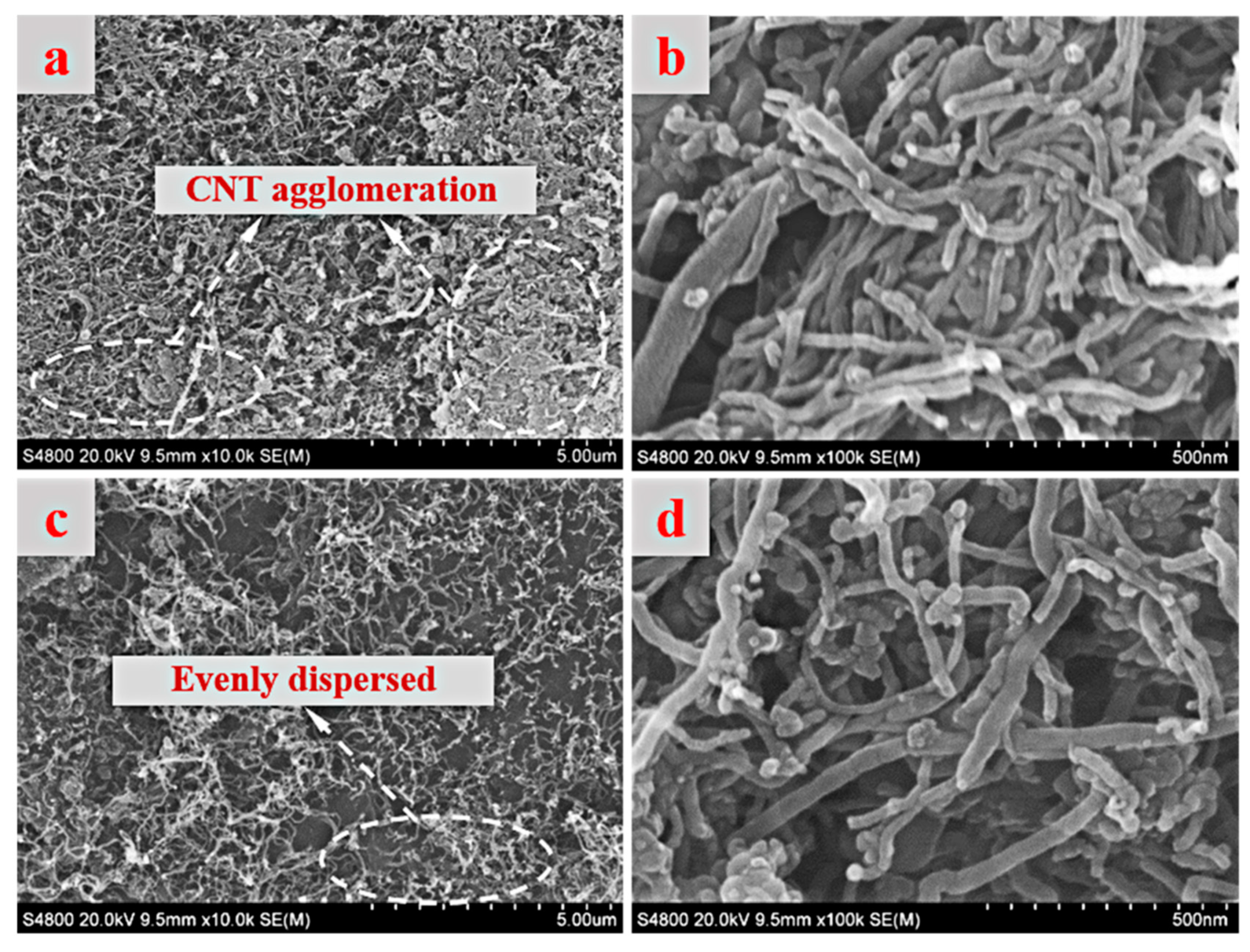
The SEM images of P–CNTs and NS–CNTs are shown in Figure 1. In the observation area, it could be seen clearly that CNTs present a typical tubular microstructure. P–CNTs trend to twine together before treatment (Figure 1a,b), resulting in serious agglomeration. By contrast, the dispersion of NS–CNTs is significantly improved and the agglomeration of NS–CNTs is alleviated (Figure 1c,d). NS–CNTs still keep their tubular morphology, due to high chemical stability and thermal stability [30], implying that introducing NS–CNTs in the HA composites is expected to maintain their original excellent mechanical properties. It can be seen that the length of NS–CNTs is reduced. The fact might be that the oxygen ions released from mixed acid solution breaks the wall of P–CNTs. The twined P–CNTs were separated, which would provide extensive deposition area for HA crystals.
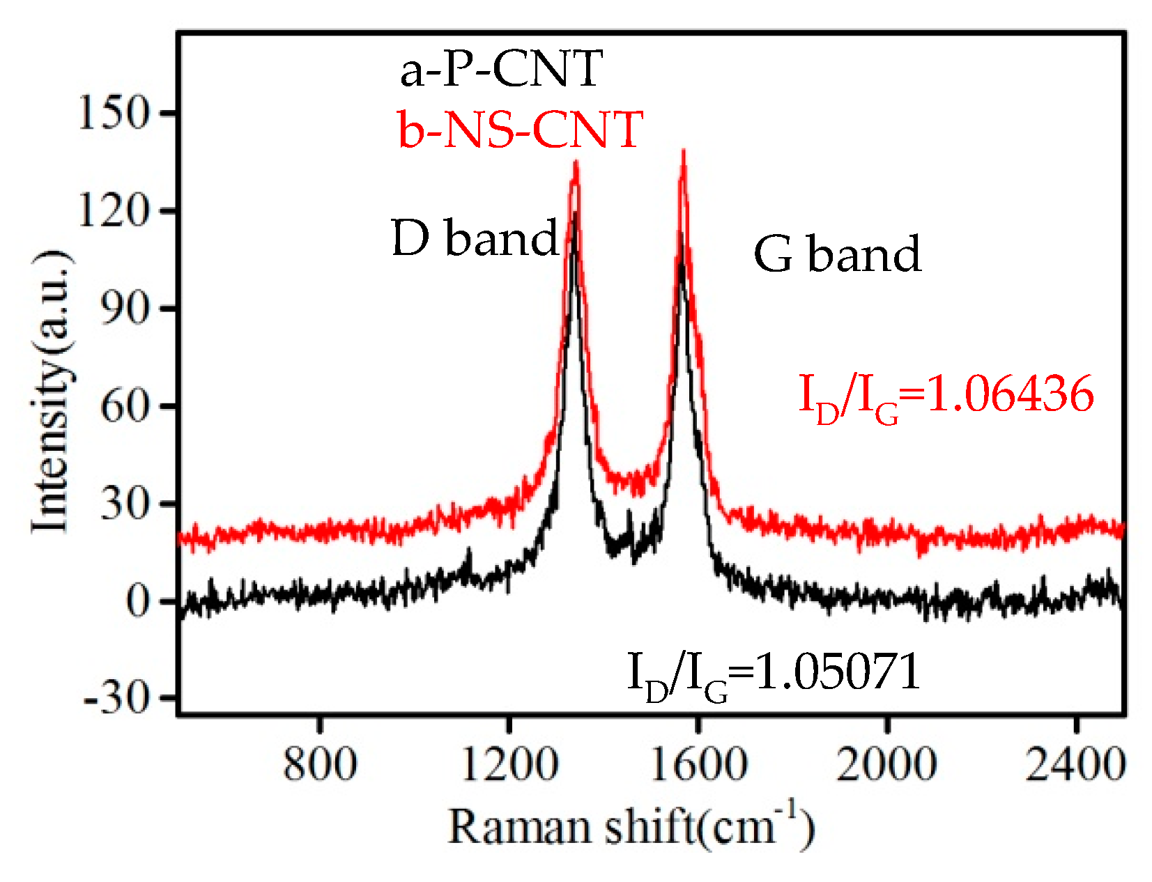
Raman spectrum is extensively used to qualitatively analyze carbonaceous materials. Figure 2 shows Raman spectrums of P–CNTs and NS–CNTs. Raman spectrum of CNTs mainly consists of two characteristic peaks, namely, the characteristic peak of D-band and G-band [31,32]. The D-band is usually associated with the presence of lattice disorders. The G-band strongly corresponds to in-plane C–C symmetric stretching vibrations in graphene sheets, which is considered to be strongly dependent on the nature and concentration of surface oxides. As shown in Figure 2, D-band and G-band of P–CNTs and NS–CNTs are observed at ~1338 cm−1 and ~1570 cm−1, respectively, which are characteristics of sp2 and sp3 bonds of hexagonal carbon structure [33]. ID/IG indexes (intensity ratio of the D-band and G-band) were calculated to be 1.050 for P–CNTs and 1.064 for NS–CNTs. It can be found that the ID/IG index for NS–CNTs is nearly P–CNTs, indicating that the NS–CNTs are degradation-free [31]. The D-band increases during the chemical oxidation of CNTs owing to abundant insertion of O-containing functional groups on their surfaces [34,35,36]. The greater value of ID/IG is, the more O-containing functional groups of CNTs are grafted [28]. The slightly increasing ID/IG index of NS–CNTs is possibly from introducing O-containing functional groups [31]. These O-containing functional groups could attract calcium cations (Ca2+) in the electrolyte to form chemical bonds, which helps to induce the nucleation and growth of HA crystals.
3.2. Electrodeposition and Biomineralization of HA Coating
Figure 3 shows SEM images of calcium phosphate (CaP) on NS–CNTs obtained by electrodeposition and nHA coating on NS-CNTs obtained by combining electrodeposition with biomineralization under different deposition times. After deposition for 15 min, there is no significant change on the surfaces of NS–CNTs (Figure 3a). On the contrary, needle-like CaP crystals are observed on the surfaces of NS–CNTs by deposition for 30 min (Figure 3b). The average diameter of CaP crystals on the NS-CNTs is around 100–200 nm. Biomineralization was applied to obtain dense and uniform nHA coating on the NS–CNTs after electrodeposition. After electrodeposition 15 min, tiny granular HA crystals are distributed on the surfaces of NS–CNTs soaked in 1.0SBF for 24 h (Figure 3c,e). However, as shown in Figure 3d,f, HA crystals present nanorod-shaped structure by biomineralization under deposition time of 30 min. Embedded figure displays the survey scan XPS spectrum of the nHA–CNTs (Figure 3g). The peaks of nHA–CNTs at 133.84, 284.6, 347.69 and 532.40 eV are attributed to P 2p, C 1s, Ca 2p and O 1s, respectively. The Ca/P molar ratio of the coating is about 1.68, which is close to the pure HA (Ca/P = 1.67). It indicates that more nuclear sites on NS–CNTs are provided after deposition for 30 min. It would facilitate nucleation and growth of HA crystals during biomineralization in 1.0SBF solution.
The development of nHA coating on NS–CNTs involves two sequent process, nucleation and growth. The nucleation processes of HA crystals are mainly governed by the Ca2+ capturing efficiency of the functional groups on the surfaces of NS–CNTs, which is called calcium immobilization. CNTs treated by mixed acid solution are possible grafted with O-containing functional groups. Therefore, these O-containing functional groups can attract Ca2+ to provide nucleation sites on the surfaces of NS–CNTs by electrodeposition. And then HA crystals grew steadily on the surfaces of NS–CNTs by biomineralization. The ion concentration (Ca2+ and PO43−) in SBF is much higher than in the electrolyte. It increases the probability of ion collisions in the coating during biomineralization. In other words, the activation energy of ions is increases, which will create a favorable condition for the growth of nHA coating.
From the above, a possible preparation mechanism of nHA coating during electrodeposition and biomineralization is proposed, as shown in Figure 4. Some C–C bonds were broken after mixed acid treatment. And NS–CNTs are grafted with O-containing functional groups, such as –COOH, –OH and –COO. When the electrodeposition begins, the O-containing functional groups could attract Ca2+ in electrolyte through coulombic forces to form a special bond. Such a bond could reduce the interfacial energy and increase the degree of supersaturation around functional groups to decrease the activation energy barrier of nucleation [37,38,39]. This phenomenon creates favorable condition for nucleation of CaP crystals. Then CaP crystals attract and react with ions (such as Ca2+ and PO34−) of 1.0SBF during biomineralization. As Ca2+ accumulating, the CNTs surface becomes positively charged and combines with the negatively charged phosphate ions, forming calcium phosphate. The CaP is eventually transformed into nanorod-shaped HA coating.
3.3. The Mechanical Properties of the Composites
The content and species of CNTs are critical factors affecting the reinforcing effect of CNTs in composites. Figure 5 shows the volume shrinkage of CNTs/HA and nHA–CNTs/HA composites. The evaporation of moisture and the fusion of grains during the sintering of composites would cause them to shrink obviously. With the increase of CNTs contents, the volume shrinkage of CNTs/HA composites presents a downward trend. Meanwhile, the volume shrinkages of HAnC1 composites are higher than those of HAC1 composites. This result may be explained by the thermal expansion coefficients of CNTs is smaller than that of HA matrix. The thermal expansion coefficient of material is an important characteristic. During the sintering of composites, the thermal expansion coefficient is proportional to the volume shrinkage. HA matrix with relatively higher thermal expansion coefficient has a large volumetric shrinkage, which is opposite to CNTs. Therefore, CNTs can effectively inhibit the volume shrinkage of composites. As nHA–CNTs are used to reinforce HA matrix, there is a little difference in the thermal expansion coefficient between nHA coating and the matrix. Therefore, the volume shrinkage of HAnC1 composites slightly increases compared to HAC1 composites. It also indicates that dense HAnC1 composites were obtained after sintering.
Figure 6 shows bending strength and elastic modulus of CNTs/HA and nHA–CNTs/HA composites. Three-points bending test is an effective method to evaluate the mechanical strength of composites [40]. As can be seen from Figure 6a, the addition of CNTs results in a decline in bending strength of CNTs/HA composites. Moreover, with the increase of CNTs content, bending strength of the composites exhibits an initial increase and subsequent decrease. This might result from difference in thermal expansion coefficients between CNTs and HA matrix and agglomeration of CNTs. Difference in thermal expansion coefficients results in a large number of interfacial gaps, which leads to the CNTs/HA composites with lower bending strength than that of HAC0 [18]. On the other hand, it is a well-established fact that agglomeration of CNTs cannot be avoided, due to the high surface energy of CNTs [41]. With the further increase in amount of CNTs, they are prone to agglomerate. The agglomeration would decrease specific surface area of CNTs and contact area between CNTs and HA matrix. Therefore, as a load is applied, the energy consumed of CNTs is reduced and the desired enhancement effect is not achieved. In addition, the agglomerated CNTs would form the stress concentration points when the CNTs/HA composites are subjected to tensile stress [42]. The stress concentration point is the source of cracks. The cracks in the composites are extended rapidly and cause the composite to break, resulting in a decrease in bending strength of the CNTs/HA composites.
For the nHA–CNTs reinforced HA composites, the bending strength of HAnC1 composites reaches a maximum (30.77 MPa), which increases by 9.30% and 26.94% compared with HAC0 and HAC1, respectively. It further suggests that preparing nHA coating on the surfaces of CNTs can effectively alleviate difference in thermal expansion coefficients between the CNTs and the HA matrix. The bonding between CNTs and HA matrix would be improved. These could increase the strengthening and toughening effects of HA-coated CNTs in CNTs/HA composites.
Figure 6b shows elastic modulus of the composites. The elastic modulus of the composites increases with the increasing CNTs content in a range from 0.5 to 1.0 wt %. It is clearly seen that the elastic modulus of HAC1 (1.26 GPa) increases by 21.2% compared with that of HAC0 (1.04 GPa). However, when the content of CNTs in the composites is higher than 1.0 wt %, the elastic modulus shows a downward trend. The value of elastic modulus of CNT is as high as approximately between 590 and 1105 GPa [43], which is much higher than that of HA (114 GPa) [44]. Generally, the addition of small content of CNTs can cause the notable increase in the elastic modulus of these CNTs reinforced HA composites according to the simple rule of mixtures [2]. It indicates that the addition of small content of CNTs makes the HA matrix more prone to recovery upon deformation [45]. Moreover, the elastic modulus of HAnC1 reaches a maximum value of 1.33 GPa, which is approximately 5.56% higher than that of HAC1. Bonding between CNTs and HA matrix is increased by fabricating a transition layer on surfaces of CNTs. Good bonding between nHA–CNTs and HA plays a role in improving the elastic modulus for the composites. When a stress is applied on the composites, the HA matrix deforms first, due to lower elastic modulus. The reinforcement interface would resist the selective elastic deformation of matrix by transferring the stress on the reinforcement [45], which results in an increase in elastic modulus of HAnC1 composites.
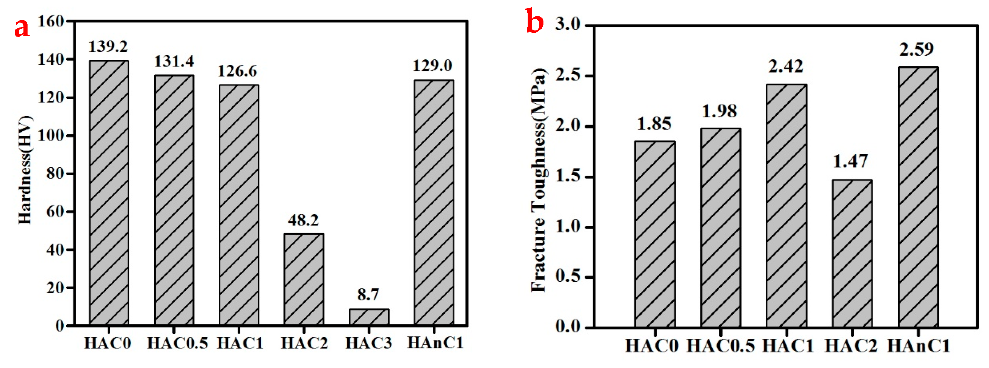
Figure 7 shows hardness and fracture toughness of CNTs/HA and nHA–CNTs/HA composites. From Figure 7a, with the increase of CNTs content, the hardness of composites decreases from 139.2 HV (HAC0) to 8.7 HV (HAC3). When the content of CNTs is 2.0 wt %, there is a drastic decrease in hardness of the composites, which decrease by 65.37% compared with HAC0. The trend of the hardness would be similar to volume shrinkages (Figure 5). The composites with large amount of CNTs have a lower volume shrinkage and densification. Therefore, the hardness of composites decreases. The hardness of HAnC1 composites is 129.0 HV, which increases by 1.9% compared with HAC1.
Figure 7b shows fracture toughness of CNTs/HA and nHA–CNTs/HA composites. With an increase of CNTs content, the fracture toughness increases to a maximum value and then decreases. When the content of CNTs increases to the value of 1.0 wt %, the CNTs/HA composite has the highest fracture toughness (2.42 MPa), which is higher than that of HAC0 (by 30.81%). Furthermore, fracture toughness of HAnC1 composites reaches a maximum 2.59 MPa, which increased by 7.02% compared with HAC1, and increased by 40% compared with HAC0 matrix, respectively. It is worth noting that the fracture toughness of HAnC1 reaches the requirements of compact bone (1.6–12.6 MPa) [46]. This suggests that nHA–CNTs reinforced HA composites would be a potential candidate as bone repair materials.
4. Conclusions
The dispersion of NS–CNTs was obviously improve by mixed acid treatment. Needle-like HA crystals were prepared on the surfaces of NS–CNTs by electrodeposition. Then nanorod-shaped HA crystals grew steadily on the surfaces of NS–CNTs by biomineralization. The bending strength of HAnC1 composites is approximately 9.3% and 26.94%—higher than those of HAC0 and HAC1 composites, respectively. The fracture toughness of HAnC1 composites reaches a maximum (2.59 MPa), which is properly within the range of that to compact bone. This work provides theoretical and practical guidance for coating on nanomaterials. It also contributes to the possible application of nHA–CNTs/HA composites for artificial bone implants.
Author Contributions
Conceptualization, X.Z.; Methodology, X.Z., X.C., and L.Z.; Validation, X.C., L.Z.; Formal Analysis, X.C., L.Z.; Investigation, X.C.; Writing–Original Draft Preparation, X.C.; Writing–Review & Editing, X.Z., Q.L., Y.W., W.Z., and J.Z.; Supervision, X.Z.
Funding
This work was funded by the National Natural Science Foundation of China (Nos. 51772179 and 51072107), the State Key Laboratory of Solidification Processing in NWPU (No. SKLSP201823), the Natural Science Basic Research Plan in Shaanxi Province of China (No. 2014JM62330), the Academic Backbone Training Program of Shaanxi University of Science and Technology, China (No. XSGP201208), the PhD research startup foundation of Shaanxi University of Science and Technology, China (No. BJ13-09) and Key Research and Development Project of Shaanxi Province (2018GY-168).
Conflicts of Interest
The authors declare no conflict of interest.
References
- Murray, M.G.S.; Wang, J.; Ponton, C.B.; Marquis, P.M. An improvement in processing of hydroxyapatite ceramics. J. Mater. Sci. 1995, 30, 3061–3074. [Google Scholar] [CrossRef]
- Chen, Y.; Zhang, Y.; Zhang, T.; Gan, C.; Zheng, C.; Yu, G. Carbon nanotube reinforced hydroxyapatite composite coatings produced through laser surface alloying. Carbon 2006, 44, 37–45. [Google Scholar] [CrossRef]
- Hench, L.L. Bioceramics: From concept to clinic. J. Am. Ceram. Soc. 1991, 74, 1487–1510. [Google Scholar] [CrossRef]
- Kobayashi, S.; Kawai, W. Development of carbon nanofiber reinforced hydroxyapatite with enhanced mechanical properties. Compos. Part A Appl. S Manuf. 2007, 38, 114–123. [Google Scholar] [CrossRef]
- Adolfsson, E.; Alberius-Henning, P.; Hermansson, L. Phase analysis and thermal stability of hot isostatically pressed zirconia–hydroxyapatite composites. J. Am. Ceram. Soc. 2000, 83, 2798–2802. [Google Scholar] [CrossRef]
- Dorner-Reisel, A.; Berroth, K.; Neubauer, R.; Nestler, K.; Marx, G.; Scislo, M.; Muller, E.; Slosarcyk, A. Unreinforced and carbon fibre reinforced hydroxyapatite: Resistance against microabrasion. J. Eur. Ceram. Soc. 2004, 24, 2131–2139. [Google Scholar] [CrossRef]
- Wei, W.; Zhu, Y.; Watari, F.; Liao, S.; Yokoyama, A.; Omori, M.; Ai, H.; Cui, F. Carbon nanotubes/hydroxyapatite nanocomposites fabricated by spark plasma sintering for bonegraft applications. Appl. Surf. Sci. 2012, 262, 194–199. [Google Scholar]
- Jong, K.D.; Geus, J. Carbon nanofibers: Catalytic synthesis and applications. J. Catal Rev. 2000, 42, 481–510. [Google Scholar] [CrossRef]
- Dai, H. Carbon nanotubes: Opportunities and challenges. Surf. Sci. 2002, 500, 218–241. [Google Scholar] [CrossRef]
- Hayashida, T.; Pan, L.; Nakayama, Y. Mechanical and electrical properties of carbon tubule nanocoils. Phys. B Condens. Matter 2002, 323, 352–353. [Google Scholar] [CrossRef]
- Sarkar, S.K.; Youn, M.H.; Oh, I.H.; Lee, B.T. Fabrication of CNT-reinforced HAp composites by spark plasma sintering. Mater. Sci. Forum 2007, 534–536, 893–896. [Google Scholar] [CrossRef]
- Xu, J.; Khor, K.; Sui, J.; Chen, W. Preparation and characterization of a novel hydroxyapatite/carbon nanotubes composite and its interaction with osteoblast-like cells. Mater. Sci. Eng. C 2009, 29, 44–49. [Google Scholar] [CrossRef]
- De Heer, W.A.; Chatelain, A.; Ugarte, D. A carbon nanotube field-emission electron source. Science 1995, 270, 1179–1180. [Google Scholar] [CrossRef]
- Di, Z.-C.; Ding, J.; Peng, X.-J.; Li, Y.-H.; Luan, Z.-K.; Liang, J. Chromium adsorption by aligned carbon nanotubes supported ceria nanoparticles. Chemosphere 2006, 62, 861–865. [Google Scholar] [CrossRef] [PubMed] [Green Version]
- Zhou, X.; Zhu, Y.; Gong, Q. Preparation and properties of the powder SBR composites filled with CNTs by spray drying process. Mater. Lett. 2006, 60, 3769–3775. [Google Scholar] [CrossRef]
- Li, C.; Tang, Y.; Yao, K.; Zhou, F.; Ma, Q.; Lin, H.; Tao, M.; Liang, J. Decoration of multiwall nanotubes with cadmium sulfide nanoparticles. Carbon 2006, 44, 2021–2026. [Google Scholar] [CrossRef]
- Kwon, Y.K.; Berber, S.; Tománek, D. Thermal contraction of carbon fullerenes and nanotubes. Phys. Rev. Lett. 2004, 92, 015901. [Google Scholar] [CrossRef] [PubMed]
- Wang, X.; Zhao, X.; Li, Z.; Wang, W.; Jing, Z.; He, F.; Yang, J. Design and fabrication of carbon fibers with needle-like nano-HA coating to reinforce granular nano-HA composites. Mater. Sci. Eng. C 2017, 77, 765–771. [Google Scholar] [CrossRef] [PubMed]
- Jiang, Y.; Zhu, Y.; Wang, F.; Chen, W. Effects of plasma and acid treatment on the dispersion of carbon nanotubes in liquids. Plasma Chem. Plasma Proc. 2011, 31, 441–448. [Google Scholar] [CrossRef]
- Okpalugo, T.I.T.; Papakonstantinou, P.; Murphy, H.; Mclaughlin, J.; Brown, N.M.D. High resolution XPS characterization of chemical functionalised MWCNTs and SWCNTs. Carbon 2005, 43, 153–161. [Google Scholar] [CrossRef]
- Zimmermann, K.A.; Leblanc, J.M.; Sheets, K.T.; Fox, R.W.; Gatenholm, P. Biomimetic design of a bacterial cellulose/hydroxyapatite nanocomposite for bone healing applications. Mater. Sci. Eng. C 2011, 31, 43–49. [Google Scholar] [CrossRef]
- Zhao, H.; Dong, W.; Zheng, Y.; Liu, A.; Yao, J.; Li, C. The structural and biological properties of hydroxyapatite-modified titanate nanowire scaffolds. Biomaterials 2011, 32, 5837–5846. [Google Scholar] [CrossRef] [PubMed]
- Wu, M.; Wang, Q.; Liu, X.; Liu, H. Biomimetic synthesis and characterization of carbon nanofiber/hydroxyapatite composite scaffolds. Carbon 2013, 51, 335–345. [Google Scholar] [CrossRef]
- Li, H.; Zhao, X.; Cao, S.; Li, K.; Chen, M.; Xu, Z.; Lu, J.; Zhang, L. Na-doped hydroxyapatite coating on carbon/carbon composites: Preparation, in vitro bioactivity and biocompatibility. Appl. Surf. Sci. 2012, 263, 163–173. [Google Scholar] [CrossRef]
- Oliveira, A.L.; Malafaya, P.B.; Reis, R.L. Sodium silicate gel as a precursor for the in vitro nucleation and growth of a bone-like apatite coating in compact and porous polymeric structures. Biomaterials 2003, 24, 2575–2584. [Google Scholar] [CrossRef] [Green Version]
- Kokubo, T.; Takadama, H. How useful is SBF in predicting in vivo bone bioactivity? Biomaterials 2006, 27, 2907–2915. [Google Scholar] [CrossRef] [PubMed]
- Yamaguchi, S.; Matsushita, T.; Kokubo, T. A bioactive Ti metal with a Ca-enriched surface layer releases Mg ions. RSC Adv. 2013, 3, 11274–11282. [Google Scholar] [CrossRef]
- Fu, S.; Yang, L.; Fan, J.; Wen, Q.; Lin, S.; Wang, B. In vitro mineralization of hydroxyapatite on electrospun poly(ε-caprolactone)-poly(ethylene glycol)-poly(ε-caprolactone) fibrous scaffolds for tissue engineering application. Colloids Surf. B Biointerface 2013, 107, 167–173. [Google Scholar] [CrossRef] [PubMed]
- Cordell, J.M.; Vogl, M.L.; Johnson, A.J.W. The influence of micropore size on the mechanical properties of bulk hydroxyapatite and hydroxyapatite scaffolds. J. Mech. Behav. Biomed. Mater. 2009, 2, 560–570. [Google Scholar] [CrossRef] [PubMed]
- Ebbesen, T.W.; Ajayan, P.M. Large-scale synthesis of carbon nanotubes. Nature 1992, 358, 220–222. [Google Scholar] [CrossRef]
- Zhou, W.; Sasaki, S.; Kawasaki, A. Effective control of nanodefects in multiwalled carbon nanotubes by acid treatment. Carbon 2014, 78, 121–129. [Google Scholar] [CrossRef]
- Hiura, H.; Ebbesen, T.W.; Tanigaki, K.; Takahashi, H. Raman studies of carbon nanotubes. Chem. Phys. Lett. 1993, 202, 509–512. [Google Scholar] [CrossRef]
- Dresselhaus, M.S.; Dresselhaus, G.; Saito, R.; Jorio, A. Raman spectroscopy of carbon nanotubes. Phys. Rep. 2005, 409, 47–99. [Google Scholar] [CrossRef]
- Estili, M.; Kawasaki, A.; Sakamoto, H.; Mekuchi, Y.; Kuno, M.; Tsukada, T. The homogeneous dispersion of surfactantless, slightly disordered, crystalline, multiwalled carbon nanotubes in α-alumina ceramics for structural reinforcement. Acta Mater. 2008, 56, 4070–4079. [Google Scholar] [CrossRef]
- Cho, J.; Boccaccini, A.R.; Shaffer, M.S.P. The influence of reagent stoichiometry on the yield and aspect ratio of acid-oxidised injection CVD-grown multi-walled carbon nanotubes. Carbon 2012, 50, 3967–3976. [Google Scholar] [CrossRef]
- Osswald, S.; Havel, M.; Gogotsi, Y. Monitoring oxidation of multiwalled carbon nanotubes by Raman spectroscopy. J. Raman Spectrosc. 2010, 38, 728–736. [Google Scholar] [CrossRef]
- Li, P.; Ohtsuki, C.; Kokubo, T.; Nakanishi, K.; Soga, N.; Groot, K.D. The role of hydrated silica, titania, and alumina in inducing apatite on implants. J. Biomed. Mater. Res. 1994, 28, 7–15. [Google Scholar] [CrossRef] [PubMed]
- Zhao, B.; Hu, H.; And, S.K.M.; Haddon, R.C. A bone mimic based on the self-assembly of hydroxyapatite on chemically functionalized single-walled carbon nanotubes. Chem. Mater. 2005, 17, 3235–3241. [Google Scholar] [CrossRef]
- Wang, X.; Li, Y.; Wei, J.; De, G.K. Development of biomimetic nano-hydroxyapatite/poly(hexamethylene adipamide) composites. Biomaterials 2002, 23, 4787–4791. [Google Scholar] [CrossRef]
- Mukherjee, S.; Nandi, S.K.; Kundu, B.; Chanda, A.; Sen, S.; Das, P.K. Enhanced bone regeneration with carbon nanotube reinforced hydroxyapatite in animal model. J. Mech. Behav. Biomed. Mater. 2016, 60, 243–255. [Google Scholar] [CrossRef] [PubMed]
- Saheb, N.; Khalil, A.; Hakeem, A.S.; Laoui, T.; Al-Aqeeli, N.; Al-Qutub, A.M. Age hardening behavior of carbon nanotube reinforced aluminum nanocomposites. J. Nano Res. 2012, 21, 29–35. [Google Scholar] [CrossRef]
- Jen, Y.M.; Huang, C.Y. Combined temperature and moisture effect on the strength of carbon nanotube reinforced epoxy materials. Transac. Can. Soc. Mech. Eng. 2013, 37, 755–763. [Google Scholar] [CrossRef]
- Jagannatham, M.; Sankaran, S.; Haridoss, P. Microstructure and mechanical behavior of copper coated multiwall carbon nanotubes reinforced aluminum composites. Mater. Sci. Eng. A 2015, 638, 197–207. [Google Scholar] [CrossRef]
- Snyders, R.; Music, D.; Sigumonrong, D.; Schelnberger, B. Experimental and ab initio study of the mechanical properties of hydroxyapatite. Appl. Phys. Lett. 2007, 90, 19390. [Google Scholar] [CrossRef]
- Lahiri, D.; Singh, V.; Keshri, A.K.; Seal, S.; Agarwal, A. Carbon nanotube toughened hydroxyapatite by spark plasma sintering: Microstructural evolution and multiscale tribological properties. Carbon 2010, 48, 3103–3120. [Google Scholar] [CrossRef]
- Yan, J. Elastic-Plastic Fracture Mechanics of Compact Bone. Ph.D. Thesis, University of Florida, Gainesville, FL, USA, January 2005. [Google Scholar]
Figure 1.
SEM images of (a,b) P-CNTs and (c,d) NS-CNTs.

Figure 2.
Raman spectra of P–CNTs and NS–CNTs.

Figure 3.
SEM images of CaP crystals on NS-CNTs under deposition time of (a) 15 min and (b) 30 min; SEM images of nHA coating on NS-CNTs under soaking in SBF for 24 h after deposition time of (c,e) 15 min and (d,f) 30 min; (g) XPS spectrum of nHA-CNTs.
Figure 3.
SEM images of CaP crystals on NS-CNTs under deposition time of (a) 15 min and (b) 30 min; SEM images of nHA coating on NS-CNTs under soaking in SBF for 24 h after deposition time of (c,e) 15 min and (d,f) 30 min; (g) XPS spectrum of nHA-CNTs.

Figure 4.
Possible preparation mechanism of nHA coating on the surfaces of CNTs.
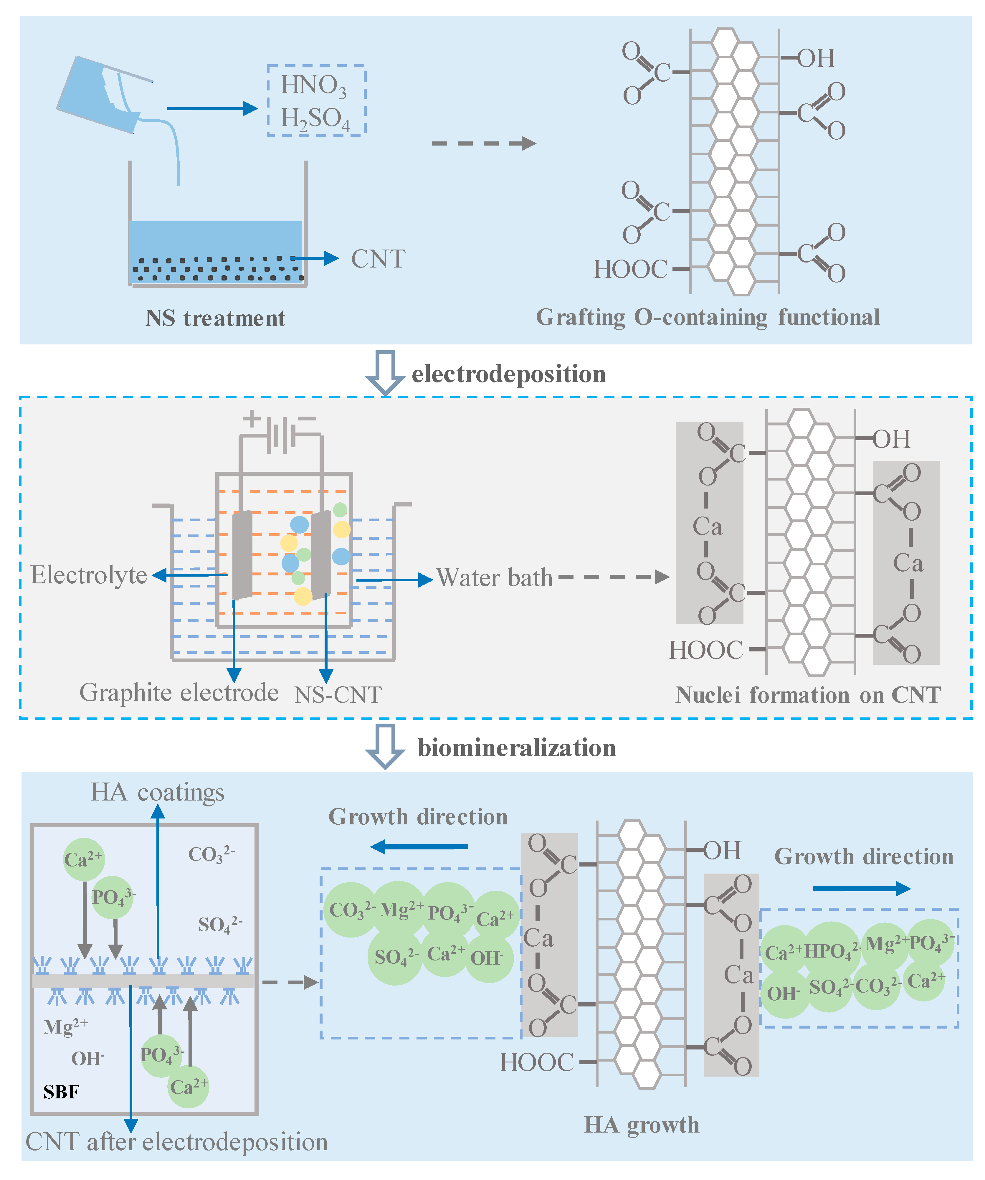
Figure 5.
The volume shrinkage of CNTs/HA and nHA–CNTs/HA composites.
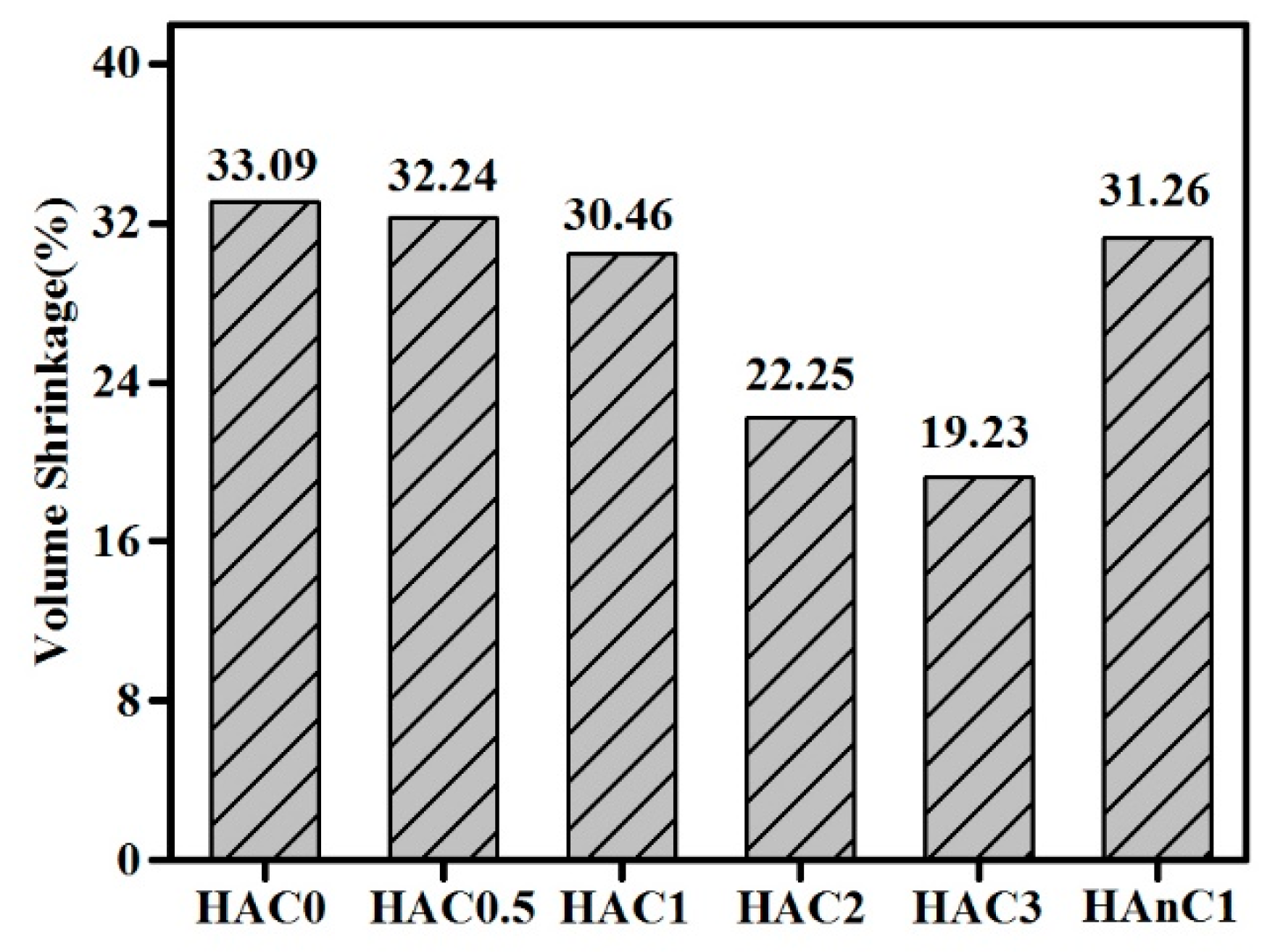
Figure 6.
(a) Bending strength and (b) elastic modulus of CNTs/HA and nHA–CNTs/HA composites.
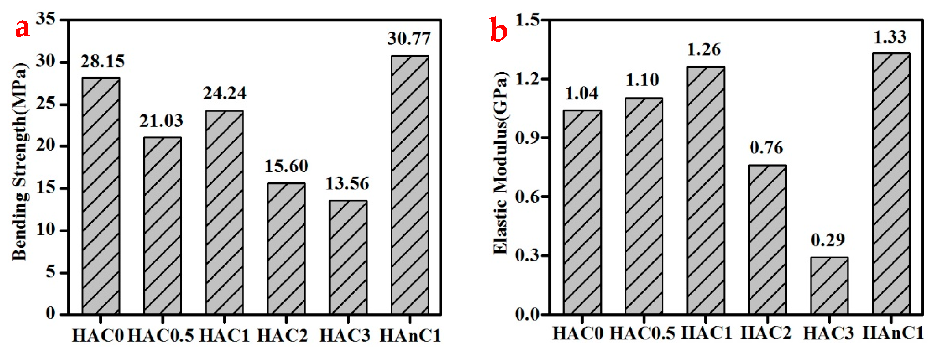
Figure 7.
(a) Hardness and (b) fracture toughness of CNTs/HA and nHA–CNTs/HA composites.
© 2018 by the authors. Licensee MDPI, Basel, Switzerland. This article is an open access article distributed under the terms and conditions of the Creative Commons Attribution (CC BY) license (http://creativecommons.org/licenses/by/4.0/).
Share and Cite
MDPI and ACS Style
Zhao, X.; Chen, X.; Zhang, L.; Liu, Q.; Wang, Y.; Zhang, W.; Zheng, J. Preparation of Nano-Hydroxyapatite Coated Carbon Nanotube Reinforced Hydroxyapatite Composites. Coatings 2018, 8, 357. https://doi.org/10.3390/coatings8100357
AMA Style
Zhao X, Chen X, Zhang L, Liu Q, Wang Y, Zhang W, Zheng J. Preparation of Nano-Hydroxyapatite Coated Carbon Nanotube Reinforced Hydroxyapatite Composites. Coatings. 2018; 8(10):357. https://doi.org/10.3390/coatings8100357
Chicago/Turabian StyleZhao, Xueni, Xueyan Chen, Li Zhang, Qingyao Liu, Yao Wang, Weigang Zhang, and Jiamei Zheng. 2018. "Preparation of Nano-Hydroxyapatite Coated Carbon Nanotube Reinforced Hydroxyapatite Composites" Coatings 8, no. 10: 357. https://doi.org/10.3390/coatings8100357
Note that from the first issue of 2016, this journal uses article numbers instead of page numbers. See further details here.