Article

Design and Fabrication of Moth-Eye Subwavelength Structure with a Waist on Silicon for Broadband and Wide-Angle Anti-Reflection Property

1
Key Laboratory of Opto-electronic Measurement and Optical Information Transmission Technology, Changchun University of Science and Technology, Changchun 130022, China
2
International Research Centre for Nano Handling and Manufacturing, Changchun University of Science and Technology, Changchun 130022, China
*
Author to whom correspondence should be addressed.
Coatings 2018, 8(10), 360; https://doi.org/10.3390/coatings8100360
Submission received: 24 August 2018 / Revised: 1 October 2018 / Accepted: 4 October 2018 / Published: 9 October 2018
(This article belongs to the Special Issue Applications of Optical Thin Film Coatings)

Abstract

:
Reflection loss on the optical component surface is detrimental to performance. Several researchers have discovered that the eyes of moths are covered with micro- and nanostructured films that reduce broadband and wide-angle light reflection. This research proposes a new type of moth-eye subwavelength structure with a waist, which is equivalent to a gradient refractive index film layer with high–low–high hyperbolic-type fill factor distribution. The diffraction order characteristics of a moth-eye subwavelength structure are first analyzed using a rigorous coupled wave analysis. The moth-eye structural parameters are optimized within the spectral range of 2–5 μm using the finite-difference time-domain method. The experimental fabrication of the moth-eye structure with a waist array upon a silicon substrate is demonstrated by using three-beam laser interferometric lithography and an inductively coupled plasma process. The experimental and simulation results show good agreement. The experimental results show that the reflectivity of the moth-eye structure with a waist is less than 1.3% when the incidence angle is less than 30°, and less than 4% when the incidence angle is less than 60°. This research can guide the development of AR broadband optical components and wide-angle applications.

1. Introduction

Fresnel reflection occurs when light travels from one medium into another owing to the large refractive index discontinuity at different medium interfaces, which can have harmful effects on the transmission and utilization of light energy [1,2,3,4]. For example, reflection in optical systems can lead to stray light such as ghost images. Slight reflections may also produce cold reflection effects, causing serious deterioration in the overall image uniformity [5,6]. Almost 30% of the energy incident on the surface of a silicon substrate is reflected, which constitutes a great loss [7].
The moth-eye structure has been developed as a new anti-reflection method with the discovery of moth-eye anti-reflection (AR) ability in bionics [8,9]. By analyzing the structure of a moth eye, scientists discovered that the outer surface of the moth eye is covered by a regular array of periodic protuberances, wherein the micro-nano structure is smaller in scale than the wavelengths of light; therefore, the waves are unable to detect the micro-nano structure [10,11]. The micro-nano structure layer can be considered as equivalent to a continuous gradient refractive index (GRIN) cover along the depth direction. It can restrain the reflection caused by refractive index saltation, because of which the moth eye has very low reflectivity. Furthermore, a bionic moth-eye microstructure array can attain high AR performance at a wide incidence angle and wide spectrum. Moreover, the structure is stable, which leads to wide application prospects in a variety of fields [12,13]. In recent years, with the development of laser interference lithography (LIL) [14,15] and accurate characterization technology of the structures [16], micro- and nanostructures have gradually achieved high precision. Schade et al. (at Martin-Luther-Universität Halle-Wittenberg) investigated the optical properties of aluminum nanoparticles deposited on glass substrates, and then used the high periodic symmetry of the patterns formed by LIL to form regular particle arrangements for photovoltaic applications [17]. Xu et al. fabricated hydrogenated amorphous Si (a-Si:H)/SiC multilayers (MLs) on both flat Si wafers and wafers with vertically aligned Si nanowires (Si NWs) arrays to achieve cell power conversion efficiency of 11.3% [18]. Munday et al. (at the University of Maryland) deposited SiO2 nanospheres on the surface of semiconductor materials to improve the efficiency of semiconductor light absorption by approximately 15%–20% [19]. Mokariantabari et al., using block copolymers as a template, decreased the reflection on silicon substrates to below 0.2% at lower angles of incidence (AOIs), and below 2% at higher AOIs [20]. In addition, with the development of advanced and alternate fabrication structures [21,22], efforts to increase the AR performance have led to the development of moth-eye structures with various morphologies, such as cylindrical, conical, and spherical pits, and pyramidal structures [23,24]. Although some structured films have been studied for applications at oblique angles of incidence [25], the AR performance will be severely limited with increasingly oblique angles of incidence.
In this research, the broadband and wide-angle AR performance of a moth-eye structure array with a waist are studied using rigorous coupled wave analysis (RCWA). To obtain broadband and wide-angle AR performance, the moth-eye structure with a waist is optimized within the spectral range of 2–5 μm by using the finite-difference time-domain (FDTD) method, which includes the optimization of the period, structural diameter, structural height, waist-to-draw ratio, and waist height. In addition, the AR performance of a moth-eye structure with a waist array is obtained by three-beam laser interferometric lithography (TIL) and inductively coupled plasma (ICP) process. The performance is also investigated experimentally for comparison with the simulated results, and good agreement is observed between the experimental and simulated results. This research can provide new designs for moth-eye nanostructure films for AR broadband optical components and wide-angle applications.

2. Materials and Methods

In simulations, the energy transmitted by the beam is dispersed to other diffraction levels when the period of the moth-eye structure is large. This increases the optical energy loss at zero order diffraction, especially in the case of obliquely incident light. Here, we derive the Rayleigh expansion of a diffraction grating from the RCWA results. The propagation vector k at all levels of a subwavelength micro structured grating can be expressed as:
k x i = k 0 [ n 1 cos θ i ( λ / Λ ) ]
k l , y i = { k 0 [ n l 2 ( k x i / k 0 ) 2 ] 1 / 2 n l k 0 > k x i j k 0 [ ( k x i / k 0 ) 2 n l 2 ] 1 / 2 n l k 0 < k x i
where kxi and kl,yi are the components of the normal tangent to k in the reflecting and transmission regions; λ is the incident wavelength; k0= 2π/λ is the incident wave vector; θ is the angle of incidence; Λ is the structural period; and n1 is the refractive index of different media (l = 1, 2). When the diffraction wave of i is under evanescent conditions, kl,yi is an imaginary number. Under oblique incidence conditions, kl,yi is imaginary when the higher order diffraction conditions are evanescent. The refractive index of the medium should satisfy nl < kxi/k0. According to Equation (2), the evanescent condition of the reflection diffraction order can be expressed as:
Λ i λ n 1 + n 1 cos θ
The order of the diffraction efficiency is zero when the angle of incidence and period of the structure satisfy the evanescence conditions. We can maintain the AR performance by reducing the period of the structure as the angle of incidence increases. Thus, we can reduce reflection and avoid the rapid rise in reflectivity at large angles.
The moth-eye structure with a waist array is shown in Figure 1a. The subwavelength structure is arranged as a periodic array. We focus on the optical characteristics of the periodic structure without considering the influence of boundary absorption. The geometric parameters of a unit cell of a moth-eye structure are given in Figure 1b. The parameters consist of the period Λ, structural diameter D, structural height H, top diameter d1, waist diameter d2, and waist height h1. The moth-eye structure is prepared on a 500-µm thick silicon base substrate. The centroid of moth-eye element is positioned at the center of its corresponding unit cell. It is worth noting that the fluctuations in the geometric parameters, namely period, height, diameter, and position, are uniformly distributed.
The origin of the 3D coordinate axis is centered at the waist. Hence, a section of each unit of the moth-eye structure forms a hyperboloid in one dimension. The shape of the section can be expressed mathematically as:
z = z c + h 1 ( x x c a ) 2 + ( y y c b ) 2 1
where the x-axis is the direction from the center of the circle that spans the length at the waist, the y-axis is the direction from the center of the circle that spans the length at the waist, and the z-axis is perpendicular to the waist center direction. a and b are the radii of the waist along the x- and y-directions, and θ is the angle between the x-axis and the line from the origin O, to the projection point. t is the coordinate parameter. Thus, x, y, and z in the formula above are given by x = xc + acosθcosh1t, y = yc + bsinθcosh1t, z = zc + h1sinh1t.
The simulation model is shown in Figure 1c, which includes the moth-eye structure array, silicon substrate, source, air layer, and monitor. The FDTD method is applied to the calculation of the spectral characteristics of our proposed structure. FDTD method uses the plane wave source to calculate reflectivity, transmissivity, absorption, and electric field distribution. For normal incidence, the periodic boundary conditions are applied in the x- and y-directions, whereas the perfect matched layer (PML) boundary conditions are applied in the z-direction. For oblique incidence, the periodic boundary conditions are replaced by the Bloch boundary conditions in the x- and y-directions because of the phase difference of the incidence light in a simulation period.

3. Results and Discussion

In order to prove that the moth-eye structure with a waist has superior AR property to a moth-eye structure without a waist (truncated-cone type), a cylindrical moth-eye structure and bare silicon structure, the reflectivity from the surfaces of different shapes modeling outcome as a function of the incident wavelength is shown in Figure 2a. In the simulation, the moth-eye structures of different shapes have the same period, structural diameter, and height (Λ = 1 μm, D = 800 nm, and H = 1.5 μm, respectively). As the simulation results show, the cylindrical moth-eye structure has high reflectivity and large fluctuation in the 2–5 μm spectral range. Therefore, the cylindrical moth-eye structure array will not be ideal for AR applications, where a low reflectivity for a broader band is needed. The moth-eye structure without a waist array shows low reflectivity for wavelengths up to 3.5 μm, and the reflectivity shows an obvious increase for wavelengths greater than 3.5 μm. In comparison, the moth-eye structure with a waist array shows low reflectivity for the entire 2–5 μm wavelength range. The effect of shape on the AR performance can be explained by using the effective medium theory [26,27]. The effective refractive index for normal incidence (neff) can be calculated based on:
n e f f = n s 2 f + n i 2 ( 1 f )
where ns is the refractive index of the moth-eye periodic array, ni is the refractive index of air, and f is the fill factor of the moth-eye periodic array.
Figure 2b presents the effective refractive index of an air/different periodic array interface. It can be observed that the effective refractive index for the cylindrical moth-eye structure shows an abrupt change at the top of the pillar nanostructure and then maintains a constant value from the top to the bottom. Meanwhile, the effective refractive indexes for the moth-eye structure with a waist and the moth-eye structure without a waist change gradually from the top of the array to the bottom, which causes a lower reflectivity than the cylindrical moth-eye. Based on GRIN efficiency characteristics, the interfacial refractive index interval (∆n) of the moth-eye structure with a waist is smaller than that of the moth-eye structure without a waist. Based on Snell’s law, the smaller the value of ∆n, the less influence the polarized light has on the Fresnel reflectance separation. This will be conducive to the realization of large angle reflectivity reduction. Meanwhile, based on the waist structure, the moth-eye with a waist can be considered as equivalent to a three-layer AR film with the f distribution of high‒low‒high [28,29]. The f distribution curve forms a hyperbola with the change in waist height, which conforms to the long wavelength AR structure characteristics.

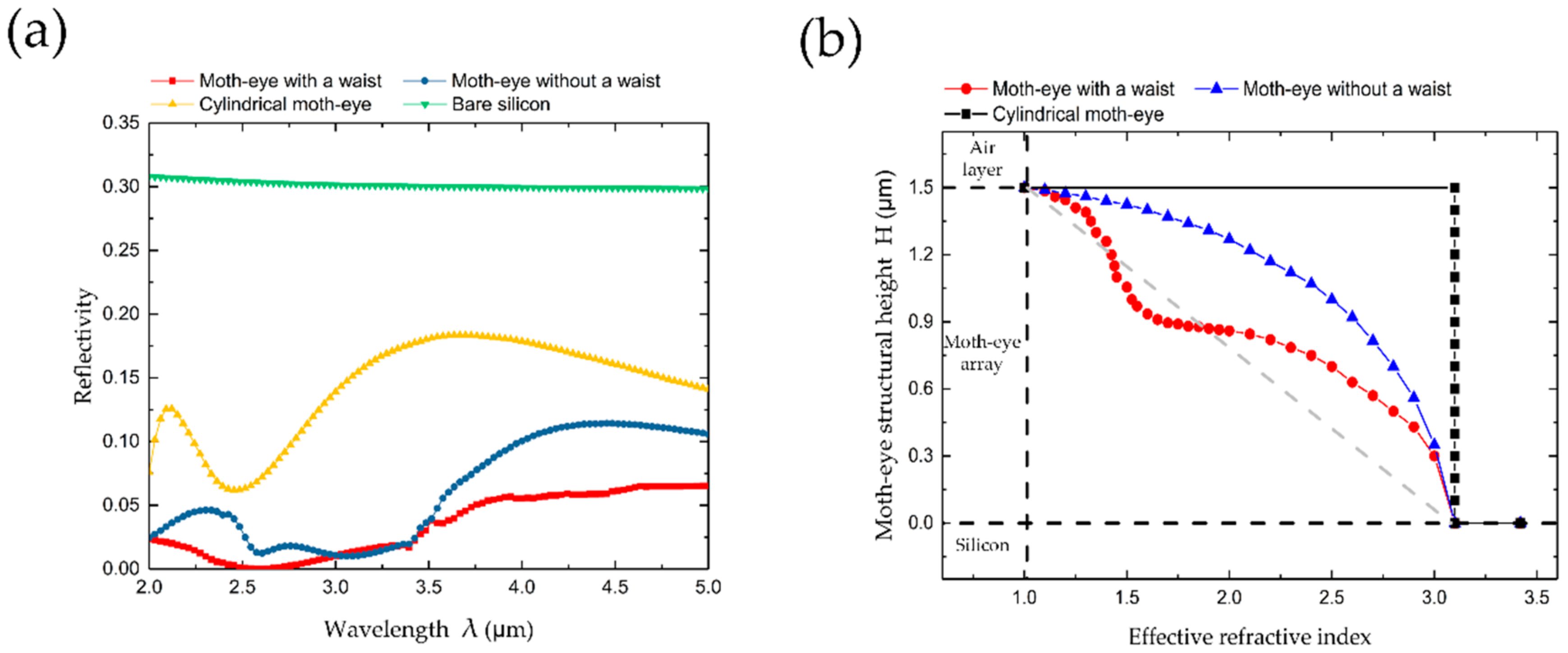
3.1. Basic Parameters of the Optimized Moth-eye Structure

FDTD is used to optimize the moth-eye structure with a waist array in the spectral range of 2–5 μm to obtain high broadband AR performance and assess the effects of the period Λ, structural diameter D, and height H. The reflectivity with different periods as a function of the incident wavelength is shown in Figure 3a. According to the theoretical calculation and actual processing requirements, the period range of 1–1.5 μm is selected to analyze the reflectivity spectrum of the moth-eye structure with a waist for which the bottom diameter and structural height are fixed (D = 500 nm and H = 1500 nm). As shown in Figure 3a, the reflectivity from the array with a relatively small period exhibits strong modulations with changing incident wavelength, whereas the modulation effect is relatively weak for an array with a bigger period. It can be concluded from Equation (3) that the period is small enough to satisfy the zero-order diffraction condition and leads to suppression of the structural reflectivity.
In addition to the period, the effect of the structural diameter is also investigated. Figure 3b shows the reflectivity of a moth-eye structure with a waist array with the diameter varying from 500 nm to 1000 nm, where the period and structural height are fixed (Λ = 1000 nm and H = 1500 nm). The simulation results show that the reflectivity reduces as the diameter increases. The phenomenon is attributed to the fact that the fill factor, which is the ratio of the moth-eye nanostructure array to the total area, reduces as the diameter reduces for the same height. Based on the effective medium theory, the effective refractive index for the bottom surface of the moth-eye nanostructure array reduces as the pitch increases, and therefore a larger refractive index discontinuity exists at the interface between the two media, which causes larger surface reflection. Based on the comparison with different structural diameters, it can provide better AR performance when the moth-eye nanostructure array bottom diameter is similar to the periodic size.
The effect of the moth-eye nanostructure height on the AR performance is also investigated. Figure 3c shows the reflectivity of the moth-eye structure with a waist array with height varying from 1.5 to 2.0 μm, where the period and structural diameter are fixed (Λ = 1000 nm and D = 500 nm). As shown in Figure 3c, the reflectivity varies little when the incident wavelength is between 2 μm and 3.5 μm, whereas the reflectivity shows a significant change when the incident wavelength is greater than 3.5 μm. It is possible that the moth-eye structure with smaller height cannot be identified due to the larger wavelength spectrum, and it is equivalent to a plane film, in which the anti-reflection property is not obvious. On the other hand, the refractive index gradient interval (∆n) decreases with the height increase. According to the layered medium theory, the influence of Fresnel reflection on the dielectric layer is not obvious, which is conducive to the broadband anti-reflection performance. The reflectivity of moth-eye structure is calculated based on RCWA. The different diffraction order of the silicon moth-eye substrate is shown in Figure 3d. In the simulation result, the reflectivity of the +1 order diffraction is zero (R[0 1] = 0) when Λ/λ ≤ 1.

3.2. Optimization of Waist Structure Parameters

Considering the superior AR performance of the moth-eye structure with a waist, we further studied the effect of the waist parameters on the broadband and wide-angle AR characteristics through a simulation. Based on the optimization of the basic parameters of the moth-eye, we selected the optimized structural parameters—Λ = 1 μm, D = 1 μm, and H = 2.0 μm—to optimize the waist structure. To investigate the effect of the waist-to-draw ratio (d1/d2) on the reflectivity performance with the incident wavelength, the simulated results of the spectral curves for d1/d2 = 1.5, 1.6, 1.7, 1.8, 1.9, and 2.0 are presented in Figure 4a. The change in the waist-to-draw ratio alters the refraction distribution of the waist film. It is clear that the AR performance is sensitive to the waist-to-draw ratio and the reflectivity is significantly reduced when the waist-to-draw ratio is relatively small. When the waist-to-draw ratio decreases, that is, the effective refractive index of the intermediate transition layer is small enough, the broadband and wide-angle AR performance of the moth-eye structure with a waist are superior.
In addition, the reflectivity for variation in the waist height (h1) from 200 to 450 nm with the change in the incident wavelength is shown in Figure 4b. The waist height represents the longitudinal waist dimension. The effective refractive index of the AR medium layer will change with the change in the waist height. It is clear that the reflectivity decreases gradually as the waist height increases. A possible reason for this phenomenon may be that the high‒low‒high distribution of the three-level AR film on the waist is more obvious, which allows the AR performance of the hyperbolic distribution to be fully realized. The structures become more difficult to manufacture with the existing processing technology as the waist-to-draw ratio and waist height optimization. We can effectively improve the AR performance by selecting the actually machined waist structure sizes.
The reflection characteristics of the moth-eye structure array for oblique incident angles are also investigated. Figure 5 shows the calculated reflectivity of the structure array with incident angles of 0°, 15°, 30°, 45°, and 60°, where Λ = 1 μm, D = 1 μm, H = 2.0 μm, d1/d2 = 1.5, and h1 = 450 nm. When the incident angle is less than 30°, the reflectivity of the moth-eye structure with a waist shows no obvious changes as the incident angle is varied, and reflectivity of less than 1.3% is observed in the 2–5 μm wavelength range. When the incident angle is 45° and 60°, the reflectivity slightly increases but the overall reflectivity is still less than 4% at wide-angle oblique incidence. However, for the moth-eye structure without a waist (truncated-cone-type for which Λ = 1 μm, D = 1 μm, H = 2.0 μm), the reflectivity over the spectral range rapidly increases when the incident angle is larger than 30°. This is because the average refractive index profile from air to the silicon substrate changes considerably from the case at normal incidence. The effective refractive index distribution of the moth-eye structure with a waist can effectively reduce the sudden change in the optical path and refractive index medium layer at the wide-angle oblique incidence and improve the AR efficiency.

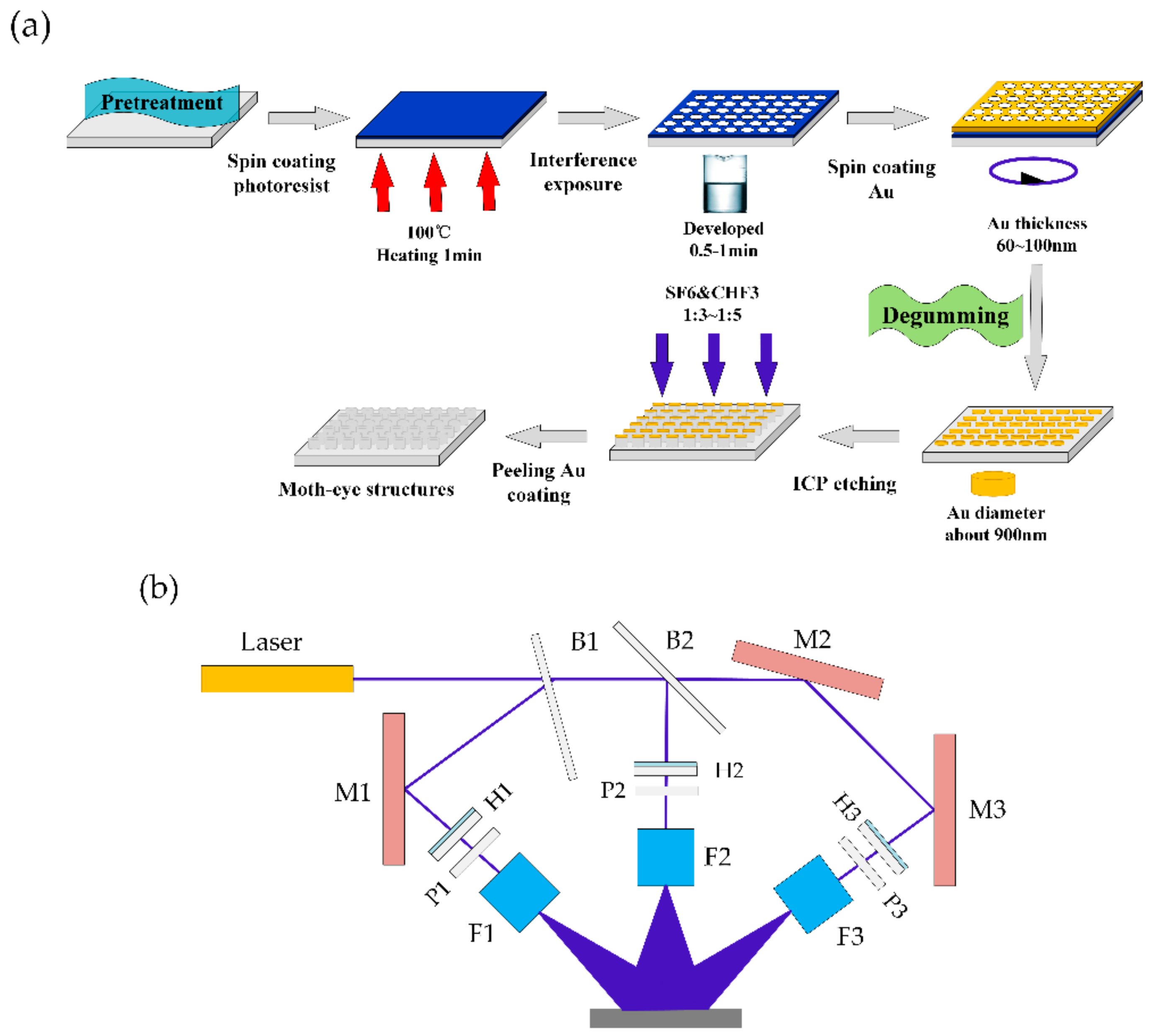
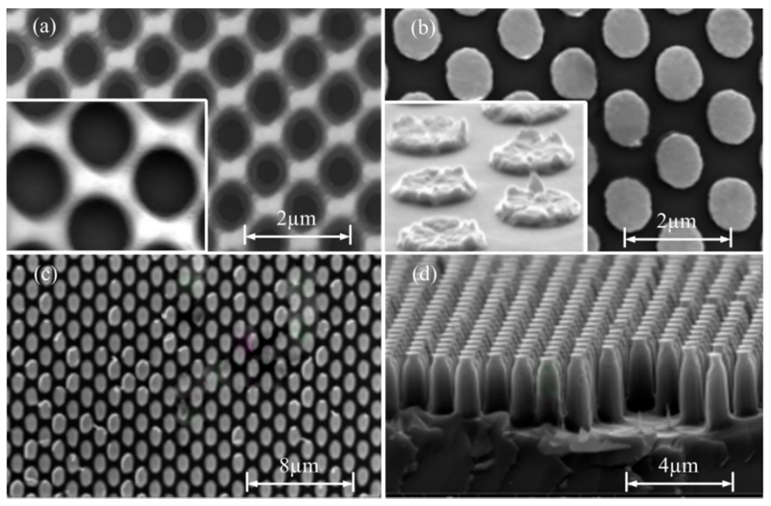
3.3. Fabrication Process and Results

The fabrication process for the optimized design of the subwavelength structure is shown in Figure 6a. The moth-eye structure with a waist is fabricated by TIL and ICP etching. In the manufacturing process, the photoresist model is AR-3740 and solid-state lasers (Prime grade, MSL-FN-360-S, CNI, Changchun, China; laser power density: 3 mW·cm−2; wavelength: 360 nm) are used. In the experiment, the designed interference patterns are obtained by the TIL system (Changchun University of Science and Technology, Changchun, China) on a substrate, as shown in Figure 6b. The irradiating source is 360 nm solid-state laser with the coherence length over 50 m and the maximum power 50 mW. The output laser beam is divided into three by beam splitters, and quarter wave plates and polarizers are placed before the sample to precisely control the power and polarization angle of the three beams. The focusing lens and the diameter pinholes are used to optimize the beams to obtain the target interference pattern. Figure 7 shows a scanning electron microscopy (SEM, Quanta 250, FEI, Hillsboro, OR, USA) image of the fabricated samples. SEM is used to characterize the surface morphologies of the templates. Figure 7a shows that various pore array structures are obtained by varying the aperture size to control the exposure. Figure 7b shows the gold mask array structures obtained after the degumming treatment. A 60–100-nm-thick Au coating (Q150T ES) is then applied to the sample. Figure 7c and d show the moth-eye structure with the array (structure period: 970 nm; etching depth: 2.1 µm; waist-to-draw ratio: 1.52; waist height: 470 nm; base diameter: 950 nm). The non-uniformity and dimension errors, compared with simulation results, are caused by the non-uniformity of the etching gas, the etching temperature and pressure, and environmental factors. By optimizing the mask thickness, etching time, and gas ratio, the overall errors from the experiment and the simulation fall within an acceptable range are in good agreement with the simulation results.
The broadband and wide-angle reflectivity are characterized using the Fourier transform infrared (FT-IR) spectrometer (Spectrum GX, PerkinElmer, Waltham, MA, USA). The measurement of the reflectivity is conducted with an oblique incidence angle (6°, 30°, and 60°) with respect to the normal incident light beam. The simulated and measured values of reflectivity with the moth-eye structure array as a function of the wavelength are shown in Figure 8. It can be observed from the measurement results that the difference in the reflectivity between the experimental and simulated results is very small; the reflectivity error range is less than 0.6% in the 2–5 μm range. Therefore, the experimental results are highly consistent with the simulated results.

4. Conclusions

In this research, a moth-eye structure with a waist array for broadband and wide-angle AR application is designed and fabricated. It is proved that the optimized moth-eye structure with a waist has better AR properties than the moth-eye structure without a waist, the cylindrical moth-eye structure, and bare silicon structure. The effects of the array period, structural height, structural diameter, waist-to-draw ratio, and waist height of the moth-eye structure with a waist on the AR performance are investigated using FDTD. Then, the moth-eye structure with a waist array is fabricated using TIL and ICP process. The experimental results are highly consistent with the simulated results in the 2–5 μm range. The moth-eye structure with a waist inhibits the increase in reflectivity under broadband and wide-angle incidence. This research provides a favorable research direction for the development of broadband and wide-angle AR coatings.

Author Contributions

Conceptualization, H.L. and Y.F.; Methodology, H.L.; Software, H.L.; Validation, H.L., M.O., B.C. and N.L.; Formal Analysis, Y.F.; Investigation, H.L. and J.W.; Resources, Z.W. and L.D.; Data Curation, Q.Z.; Writing—Original Draft Preparation, H.L.; Writing—Review & Editing, Y.F.; Project Administration, Y.F.; Funding Acquisition, Y.F.

Funding

This research was funded by National Natural Science Foundation of China (Nos. 51505078, 61705018) and the 111 Project of China (No. D17017).

Acknowledgments

The authors thank the Key Laboratory of Advanced Optical System Design and Manufacturing Technology of the universities of Jilin Province for the SEM technical support.

Conflicts of Interest

The authors declare no conflict of interest.

References

  1. Li, J.; Zhu, J.; Gao, X. Bio-inspired high-performance antireflection and antifogging polymer films. Small 2014, 10, 2578–2582. [Google Scholar] [CrossRef] [PubMed]
  2. Raut, H.K.; Dinachali, S.S.; Loke, Y.C.; Ganesan, R.; Ansahantwi, K.K.; Góra, A. Multiscale ommatidial arrays with broadband and omnidirectional antireflection and antifogging properties by sacrificial layer mediated nanoimprinting. ACS Nano 2015, 9, 1305–1314. [Google Scholar] [CrossRef] [PubMed]
  3. Askar, K.; Phillips, B.M.; Jiang, B. Bioinspired self-cleaning antireflection coatings. Adv. Mater. 2015, 20, 65–95. [Google Scholar]
  4. Yang, Y.; Pillai, S.; Mehrvarz, H.; Green, M.A. Plasmonic degradation and the importance of over-coating metal nanoparticles for a plasmonic solar cell. Sol. Eng. Mat. Sol. Cell. 2014, 122, 208–216. [Google Scholar] [CrossRef]
  5. Bychanok, D.; Li, S.; Gorokhov, G.; Piasotski, K.; Meisak, D.; Kuzhir, P. Fully carbon metasurface: Absorbing coating in microwaves. J. Appl. Phys. 2017, 121, 2075–2084. [Google Scholar] [CrossRef]
  6. Ko, D.H.; Tumbleston, J.R.; Gadisa, A.; Aryal, M.; Liu, Y.; Lopez, R. Light-trapping nano-structures in organic photovoltaic cells. J. Mater. Chem. 2011, 21, 16293–16303. [Google Scholar] [CrossRef]
  7. Voroshilov, P.M.; Simovski, C.R.; Belov, P.A.; Shalin, A.S. Enhancement of photovoltaic absorption in thin-film silicon solar cells by all-dielectric light-trapping and antireflective coatings. In Proceedings of the 2015 9th International Congress on Advanced Electromagnetic Materials in Microwaves and Optics (METAMATERIALS), Oxford, UK, 7–12 September 2015; pp. 517–519. [Google Scholar]
  8. Loh, J.; Kherani, N. Design of nano-porous multilayer antireflective coatings. Coatings 2017, 7, 134. [Google Scholar] [CrossRef]
  9. Cao, W.; Myers, J.D.; Zheng, Y.; Hammond, W.T.; Wrzesniewski, E.; Xue, J. Enhancing light harvesting in organic solar cells with pyramidal rear reflectors. Appl. Phys. Lett. 2011, 99, 135. [Google Scholar] [CrossRef]
  10. Glass, R.; Möller, M.; Spatz, J.P. Block copolymer micelle nanolithography. Nanotechnology 2003, 14, 1153–1160. [Google Scholar] [CrossRef]
  11. Ono, Y.; Kimura, Y.; Ohta, Y.; Nishida, N. Antireflection effect in ultrahigh spatial-frequency holographic relief gratings. Appl. Opt. 1987, 26, 1142–1146. [Google Scholar] [CrossRef] [PubMed]
  12. Bruynooghe, S.; Schulze, M.; Helgert, M.; Challier, M.; Tonova, D.; Sundermann, M. Broadband and wide-angle hybrid antireflection coatings prepared by combining interference multilayers with subwavelength structures. J. Nanophotonics 2016, 10, 033002. [Google Scholar] [CrossRef]
  13. Min, W.L.; Jiang, B.; Jiang, P. Bioinspired self-cleaning antireflection coatings. Adv. Mater. 2008, 20, 3914–3918. [Google Scholar] [CrossRef]
  14. Grilli, S.; Ferraro, P.; De Natale, P.; Tiribilli, B. Surface nanoscale periodic structures in congruent lithium niobate by domain reversal patterning and differential etching. Appl. Phys. Lett. 2005, 87, 233106. [Google Scholar] [CrossRef]
  15. Rianna, C.; Calabuig, A.; Ventre, M.; Cavalli, S.; Pagliarulo, V.; Grilli, S.; Ferraro, P.; Netti, P.A. Reversible holographic patterns on azopolymers for guiding cell adhesion and orientation. ACS Appl. Mater. Interfaces 2015, 7, 16984–16991. [Google Scholar] [CrossRef] [PubMed]
  16. De Nicola, S.; Ferraro, P.; Finizio, A.; Grilli, S.; Coppola, G.; Iodice, M.; De Natale, P.; Chiarini, M. Surface topography of microstructures in lithium niobate by digital holographic microscopy. Meas. Sci. Technol. 2004, 15, 961. [Google Scholar] [CrossRef]
  17. Schade, M.; Fuhrmann, B.; Bohley, C.; Schlenker, S.; Sardana, N.; Schilling, J. Regular arrays of Al nanoparticles for plasmonic applications. J. Appl. Phys. 2014, 115, 205–213. [Google Scholar] [CrossRef]
  18. Cao, Y.; Ge, Z.; Jiang, X.; Xu, J.; Xu, L.; Li, W. Light harvesting and enhanced performance of Si quantum dot/Si nanowire heterojunction solar cells. Part. Part. Syst. Charact. 2016, 33, 38–43. [Google Scholar] [CrossRef]
  19. Ha, D.; Chen, G.; Leite, M.S.; Munday, J.N. Demonstration of resonance coupling in scalable dielectric micro-resonator coatings for photovoltaics. ACS Appl. Mater. Interfaces 2016, 8, 24536. [Google Scholar] [CrossRef] [PubMed]
  20. Mokariantabari, P.; Senthamaraikannan, R.; Glynn, C.; Collins, T.W.; Cummins, C.; Nugent, D.; O'Dwyer, C.; Morris, M. Large block copolymer self-assembly for fabrication of subwavelength nanostructures for applications in optics. Nano Lett. 2017, 17, 2973–2978. [Google Scholar] [CrossRef] [PubMed]
  21. Merola, F.; Grilli, S.; Coppola, S.; Vespini, V.; De Nicola, S.; Maddalena, P.; Carfagna, C.; Ferraro, P. Reversible fragmentation and self-assembling of nematic liquid crystal droplets on functionalized pyroelectric substrates. Adv. Funct. Mater. 2012, 22, 3267–3272. [Google Scholar] [CrossRef]
  22. Grilli, S.; Coppola, S.; Vespini, V.; Merola, F.; Finizio, A.; Ferraro, P. 3D lithography by rapid curing of the liquid instabilities at nanoscale. Proc. Natl. Acad. Sci. 2011, 108, 15106–15111. [Google Scholar] [CrossRef] [PubMed] [Green Version]
  23. Shi, G.; Chen, J.; Wang, L.; Wang, D.; Yang, J.; Li, Y. Titanium oxide/silicon moth-eye structures with antireflection, p-n heterojunctions and superhydrophilicity. ACS J. Surf. 2016, 32, 41. [Google Scholar] [CrossRef] [PubMed]
  24. Zhang, C.; Yi, P.; Peng, L.; Ni, J. Optimization and continuous fabrication of moth-eye nanostructure array on flexible polyethylene terephthalate substrate towards broadband antireflection. Appl. Opt. 2017, 56, 2901. [Google Scholar] [CrossRef] [PubMed]
  25. Chen, Q.; Shields, P.; Liu, C.W.; Allsopp, D.W.E. Broadband moth-eye antireflection coatings fabricated by low-cost nanoimprinting. Appl. Phys. Lett. 2009, 94, 263118. [Google Scholar] [CrossRef]
  26. Li, Y.; Zhang, J.; Yang, B. Antireflective surfaces based on biomimetic nanopillared arrays. Nano Today 2010, 5, 117–127. [Google Scholar] [CrossRef]
  27. Wu, F.; Shi, G.; Xu, H.; Liu, L.; Wang, Y.; Qi, D. Fabrication of antireflective compound eyes by imprinting. ACS Appl. Mater. Interfaces 2013, 5, 12799–12803. [Google Scholar] [CrossRef] [PubMed]
  28. Shen, Z.C.; Shao, J.D.; Wang, Y.J.; Fan, Z.X. Theoretical study of graded-index coatings prepared by glancing angle deposition. Acta Phys. Sin. 2005, 54, 3069–3074. [Google Scholar]
  29. Shen, Z.C.; Shen, J.; Liu, S.J.; Kong, W.J.; Shao, J.D.; Fan, Z.X. Discussion on the stratified merit of graded index coatings. Acta Phys. Sin. 2007, 56, 1325–1328. [Google Scholar]
Figure 1. Model of the moth-eye structure with the waist: (a) three-dimensional (3D) diagram of the simulated model; (b) 3D diagram of the designed coordinate parameters of the moth-eye structure unit; (c) schematic diagram of the simulation model.
Coatings 08 00360 g001
Figure 2. Reflectivity and effective refractive index of moth-eye structures with different morphologies (normal incidence): (a) comparison of the reflectivity of moth-eye structures with different morphologies; (b) comparison of the effective refractive index of moth-eye structures with different morphologies.
Coatings 08 00360 g002
Figure 3. Optimized basic parameters of moth-eye structure with a waist (normal incidence): (a) reflectivity of structure array with D = 500 nm, H = 1500 nm, and Λ = 1.0–1.5 μm; (b) reflectivity of structure array with Λ = 1000 nm, H = 1500 nm, and D = 500‒1000 nm; (c) reflectivity of structure array with Λ = 1000 nm, D = 500 nm, and H = 1.5–2.0 μm; (d) reflectivity of different diffraction gradation (R[0 0] is reflectivity of 0 order diffraction, R[0 1] is reflectivity of +1 order diffraction, R[1 1] is reflectivity of higher order diffraction).
Coatings 08 00360 g003
Figure 4. Optimized waist structure parameters: (a) reflectivity of structure array with h1 = 450 nm, and d1/d2 = 1.5–2.0; (b) reflectivity of structure array with d1/d2 = 1.5, and h1 = 200–450 nm.
Coatings 08 00360 g004
Figure 5. The reflection characteristics of the moth-eye structure with a waist array for oblique incident angles, comparing with the moth-eye structure without a waist.
Coatings 08 00360 g005
Figure 6. Fabrication process of moth-eye structure with a waist. (a) Processing flow of TIL and ICP etching; (b) schematic setup of the TIL system: B-Beam splitter (B1, B2), M-Mirror (M1, M2, M3), W-1/4 wave plate (W1, W2, W3), P-Polarizer (P1, P2, P3), L-Lens (L1, L2, L3) and PH-Pinhole (PH1, PH2, PH3).
Coatings 08 00360 g006
Figure 7. SEM images of (a) laser interference lithography of photoresist mask pattern; (b) Au coating deposited onto the lithography template before ICP etching; (c) top view and (d) side view of the moth-eye structure with a waist on intrinsic silicon wafer.
Coatings 08 00360 g007
Figure 8. Experimental and simulated reflectivity of moth-eye structure with a waist for broadband and wide-angle. The feature dimension is a circular area with a diameter of 35 mm.
Coatings 08 00360 g008

