Article

Isothermal Oxidation Behavior of Zr-Y Coating on γ-TiAl by Double Glow Plasma Surface Metal Alloying Technique

1
College of Materials Science and Technology, Nanjing University of Aeronautics and Astronautics, Nanjing 211106, China
2
Jiangsu Key Laboratory of Advanced Structural Materials and Application Technology, Nanjing 211167, China
3
Key Laboratory of Materials Preparation and Protection for Harsh Environment (Nanjing University of Aeronautics and Astronautics), Ministry of Industry and Information Technology, Nanjing 211106, China
*
Author to whom correspondence should be addressed.
Coatings 2018, 8(10), 361; https://doi.org/10.3390/coatings8100361
Submission received: 23 August 2018 / Revised: 30 September 2018 / Accepted: 4 October 2018 / Published: 12 October 2018
(This article belongs to the Special Issue Advanced Coatings for Corrosion Protection in Extreme Environments)

Abstract

:
Oxidation resistance of Zr-Y coating on γ-TiAl alloy prepared by a double-glow plasma surface alloying technique was investigated in static air at 750 °C, 800 °C and 850 °C for 100 h. A pure Zr coating was also prepared for comparison. Addition of Y improved high-temperature oxidation resistance of the alloying coating because of its refining effect and inhibition of cationic diffusion. Oxidation kinetic curves indicated that the high-temperature oxidation resistance of the Zr-Y coating was about eight times higher than that of the bare substrate and about 3 times higher than that of pure Zr coating.

1. Introduction

γ-TiAl is one of the most widely used materials in the aviation industry because of its excellent comprehensive mechanical properties, low density, and good corrosion resistance. However, at certain pressures and temperatures, it oxidizes, burns, and spreads quickly. This is often called “titanium fire” [1,2,3]. Such flammability restricts its application under certain service conditions. National aviation materials experts are searching for titanium alloy flame retardant protection [4,5,6]. Certain surface treatment methods can solve this problem [7,8]. Zhang et al. [9] demonstrated that Al2O3 film enhances oxidation resistance of Ti-alloy substrate.
Traditional methods of preparing alloy coatings include procedures such as magnetron sputtering and ion implantation [10,11]. Magnetron sputtering provides high-density and smooth coatings. However, film hardness and the adhesion strength between the film and the substrate are both poor [12,13,14]. Ion implantation provides better purity of the doped ions, and the doping concentration is not limited by the solid state solubility. Additionally, the concentration and depth distribution of the implanted ions are accurate and controllable. However, ion implantation layers are typically too thin and, thus, have short life span. In addition, an ion-beam deposited coating might not be homogeneously distributed on parts with complex shapes [15,16].
In this paper, we report a double-glow plasma surface alloying technology as a new method to deposit protective coatings on a TiAl substrate. This technology can effectively improve hardness, wear, and oxidation resistance [17,18,19] of the underlying substrate. It also allows the coating to be metallurgically bonded to the substrates without an obvious interface. This technology has high deposition rates and demonstrates great promise for a variety of engineering applications since it provides good coating uniformity and excellent control over thickness, especially for substrates with complex shapes [20].
We deposited Zr and Zr-Y coatings on TiAl substrate using double-glow plasma surface alloying technique. We analyzed the high-temperature oxidation behavior of these samples using isothermal oxidation tests at 750 °C, 800 °C and 850 °C conducted for 100 h. To understand the mechanism of the oxidation of the resulting alloys, we implemented methods such as oxidation kinetics, energy dispersive spectroscopy (EDS), X-ray diffraction (XRD), and scanning electron microscopy (SEM).

2. Experimental Section

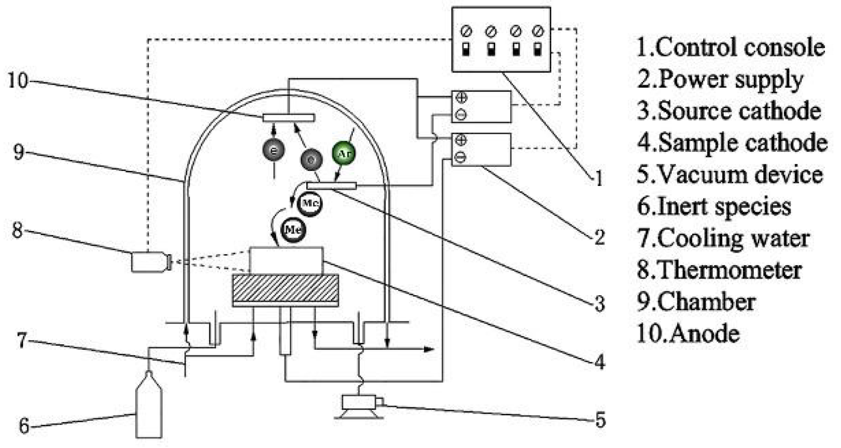
2.1. Specimen Preparation

The composition of γ-TiAl is shown in Table 1. Samples were cut into square shapes with dimensions of 14 mm × 14 mm × 4 mm. The surfaces of all the specimens were polished with SiC paper, cleaned ultrasonically in acetone to remove the oil, and then dried.
The sputtering target of a Zr-Y alloy disc prepared by powder metallurgy was used to supply the alloying elements. The double-glow plasma surface alloying process was performed in a vacuum chamber, which included three electrodes: The anode, the source electrode (Zr or Zr-Y alloy plate), and the substrate electrode (γ-TiAl alloy). Double-glow plasma surface alloying was performed as shown in Figure 1. A target electrode (TE) and a substrate electrode (SE) were mounted in a vacuum chamber (anode). The chamber was evacuated to just under 0.1 Pa and then filled with argon as a protective gas. The potential difference between the target and the substrate resulted in an unequal electronic potential hollow-cathode effect, which would spurt the ions or atoms to deposit on the substrate. The parameters for the experiment are shown in Table 2.

2.2. Oxidation Resistance Measurement

Isothermal oxidation tests were studied in air in a muffle furnace at 750 °C, 800 °C and 850 °C. The specimens were placed in Al2O3 crucibles, which were cooled to room temperature after oxidation for 100 h. An analytical balance with an accuracy of 0.1 mg was used to measure the mass changes of all samples at regular intervals during the isothermal oxidation tests. The kinetics equations of isothermal oxidation were fitted by Levenberg-Marquardt algorithms. All fitting equations followed three forms, including the cubic rate law, the logarithmic rate law, and the parabolic law, given by [21]:
y 1 3 = k c x + b x ( 0 , 100 ]
Equation (1) shows that the oxidation process was controlled by diffusion retardation due to the doping of alloy element oxides, ion diffusion and dense blocking layer:
y 2 = k l 1 ( k l 2 x + k l 3 ) x ( 0 , 100 ]
Equation (2) shows that, in the process of membrane growth, the large elastic compressive stress made the outer layer denser, slowing down the oxidation process:
y 3 2 = k p x + b x ( 0 , 100 ]
Equation (3) shows that the oxidation process was controlled by film thickness [22,23,24].
The oxidation rate functions were obtained by taking the derivative of the isothermal oxidation kinetics:
y 1 = k c 3 ( k c x + b ) 2 3 x ( 0 , 100 ]
y 2 = k l 1 k l 2 ( k l 2 x + k l 3 )   ln 10 x ( 0 , 100 ]
y 3 = k p 2 k p x + b x ( 0 , 100 ]

2.3. Characterization

The surface morphologies and cross-sections of the oxidized samples were investigated with a JSM-6360L scanning electronic microscope (SEM, JEOL Ltd., Tokyo, Japan) equipped with energy dispersive spectrum (EDS), while the phase compositions of the oxide scales were determined using Bruker D8-ADVANCE X-ray diffraction (XRD, Bruker, Billerica, MA, USA) with Cu Kα radiation over a range of 2θ from 10° to 100°.

3. Results and Discussion

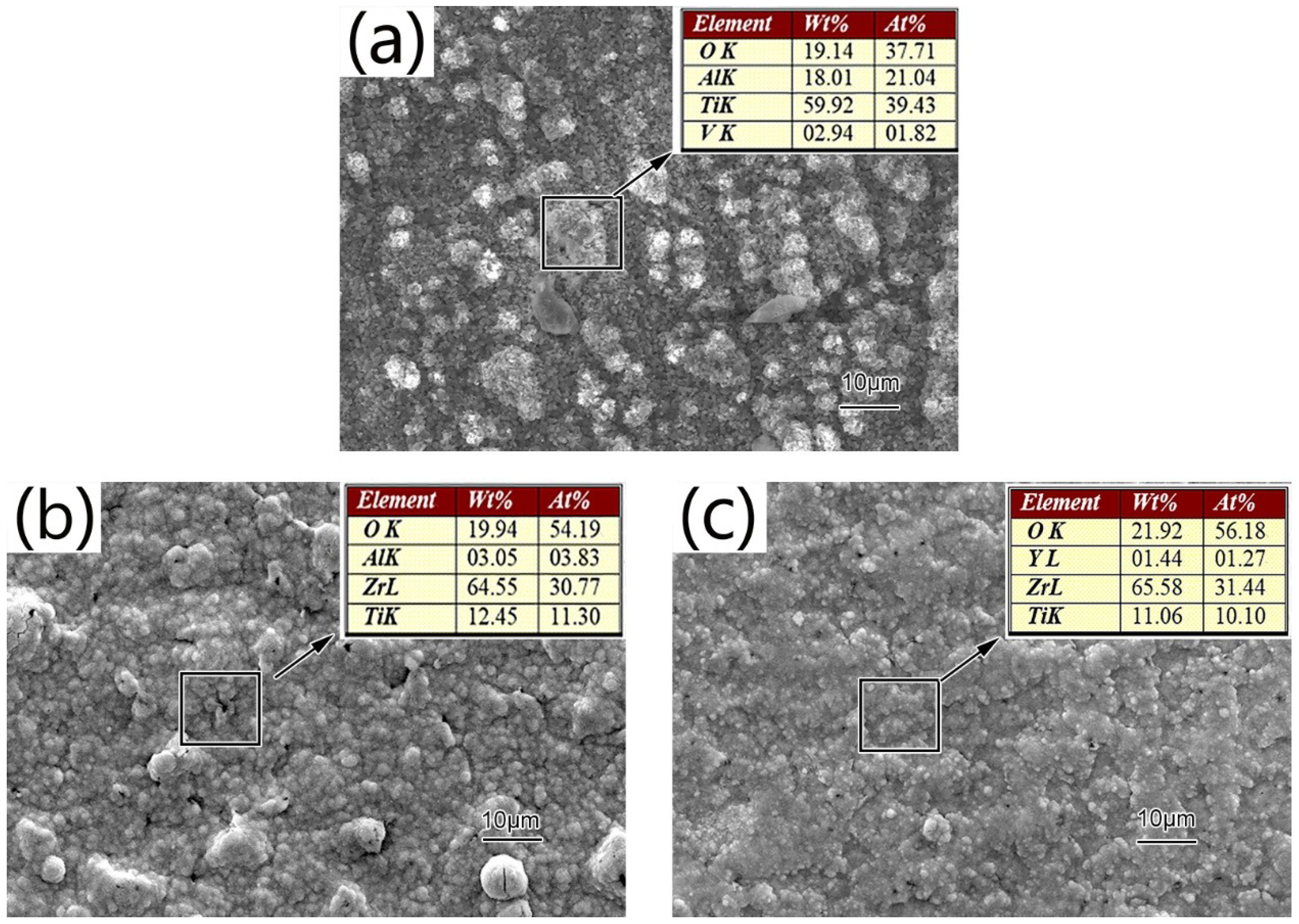
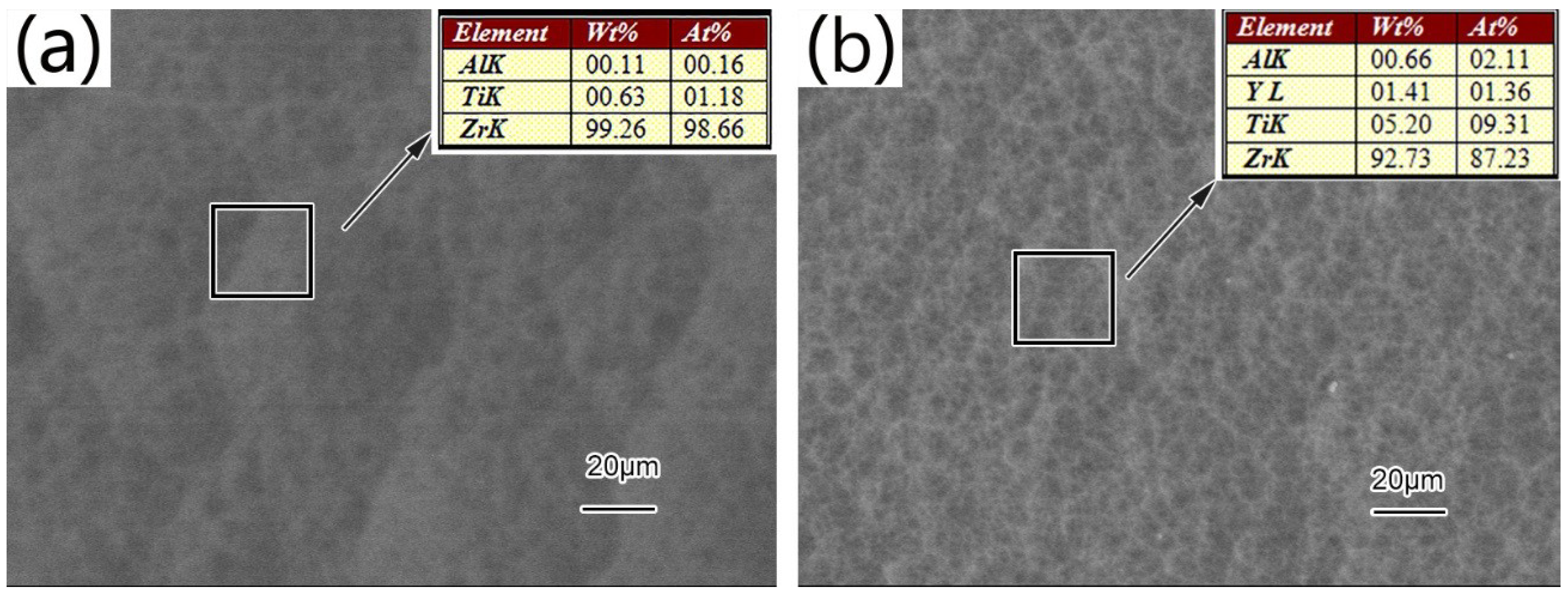
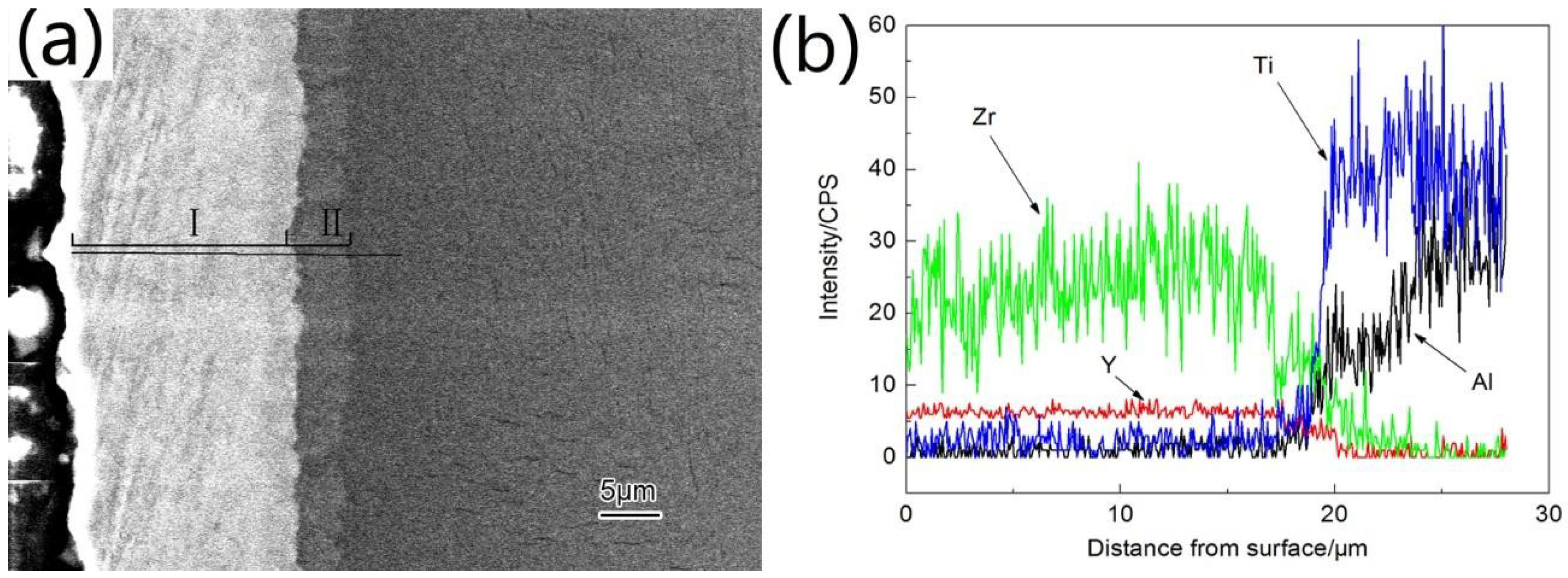
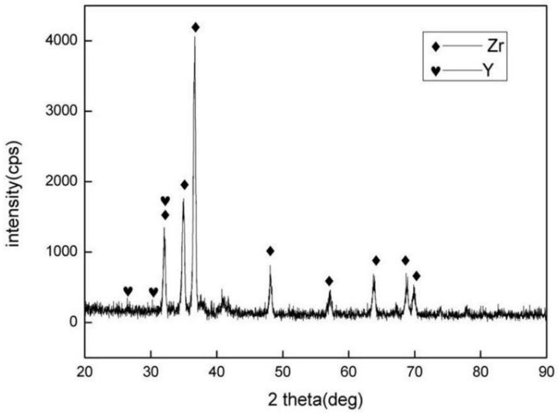
3.1. Microstructure and Phase Distribution of Coatings

As-deposited Zr coating was uniform (see Figure 2a), and the uneven particles and bulges were homogeneously dispersed and distributed on the surface of the modified layer. EDS analysis indicated that the surface was composed mostly of Zr and small quantities Ti and Al. Zr-Y coating was silver in color and looked smooth and dense and demonstrated uniform crystallinity. We believe that the addition of Y stimulated nucleation of crystal grains. Finer grains suppressed abnormal grain growth and reduced presence of micropores. EDS showed that the surface of the Zr-Y coating mainly contained 1.41 wt % of Y, 5.20 wt % of Ti and 92.73 wt % of Zr. This composition indicated significant deviation from the composition of the Zr-Y target. One explanation could be formation of infinite solid solution between Ti and Zr since their crystal structures are very similar. Another reason for this deviation could be the difference between Zr and Y sputtering energy, which affected how much of each element was actually sputtered. The thickness of the Zr-Y coating was ~25 μm (see Figure 3). The coating consisted of an outer deposition layer (zone I) and an inner diffusion layer (zone II).
Figure 3 illustrates elements distribution in the alloying coating from the surface to the substrate determined EDS. Zr and Y contents in the diffusion layer gradually decreased, while the Ti and Al contents increased (see Figure 3). This inter-diffused layer could be considered a metallurgical bond, and it improved adhesion between the coating and the substrate. Strongest XRD peaks were mainly located between 30° and 40° (see Figure 4) Diffraction peak intensity of the Zr phase was significantly higher than that of the Y phase. Zr was deposited in its elemental form, which is favorable for the formation of compact zirconia films during oxidation. Yttrium dispersed in the coating provided coating with the thermal barrier properties.

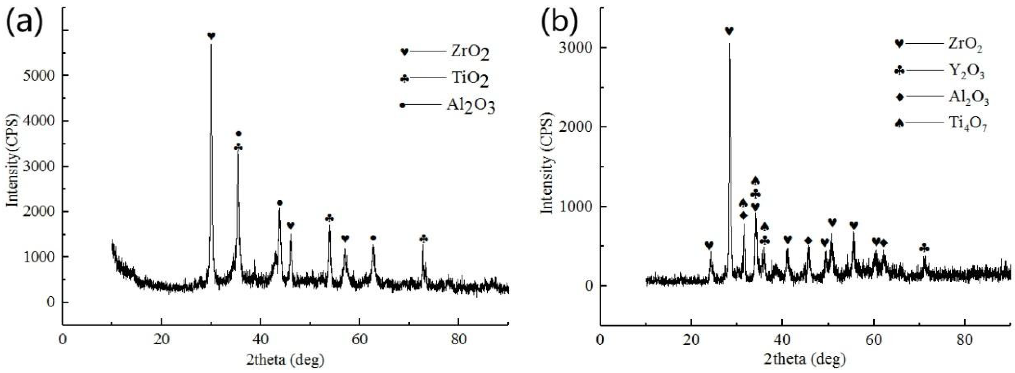
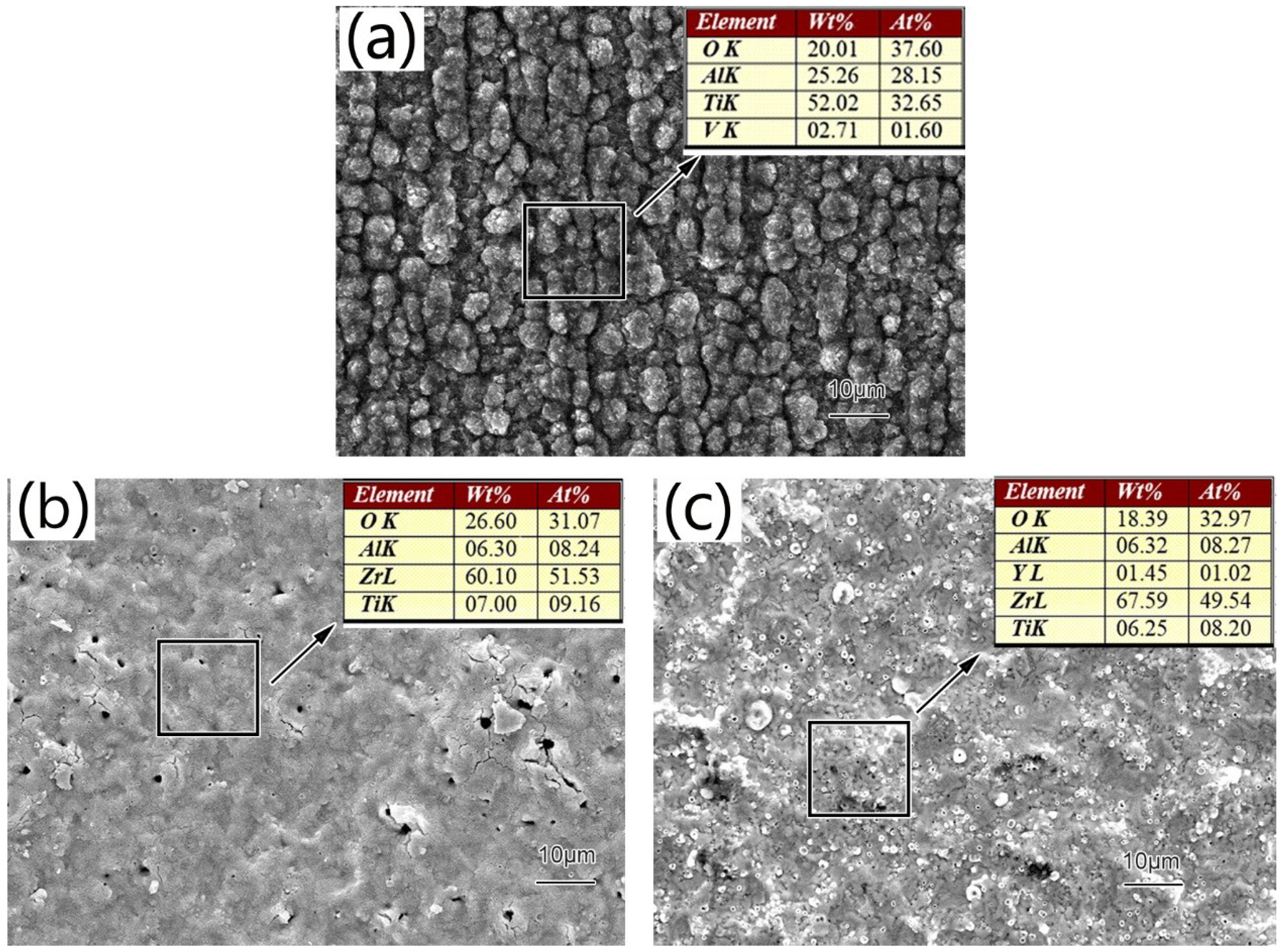
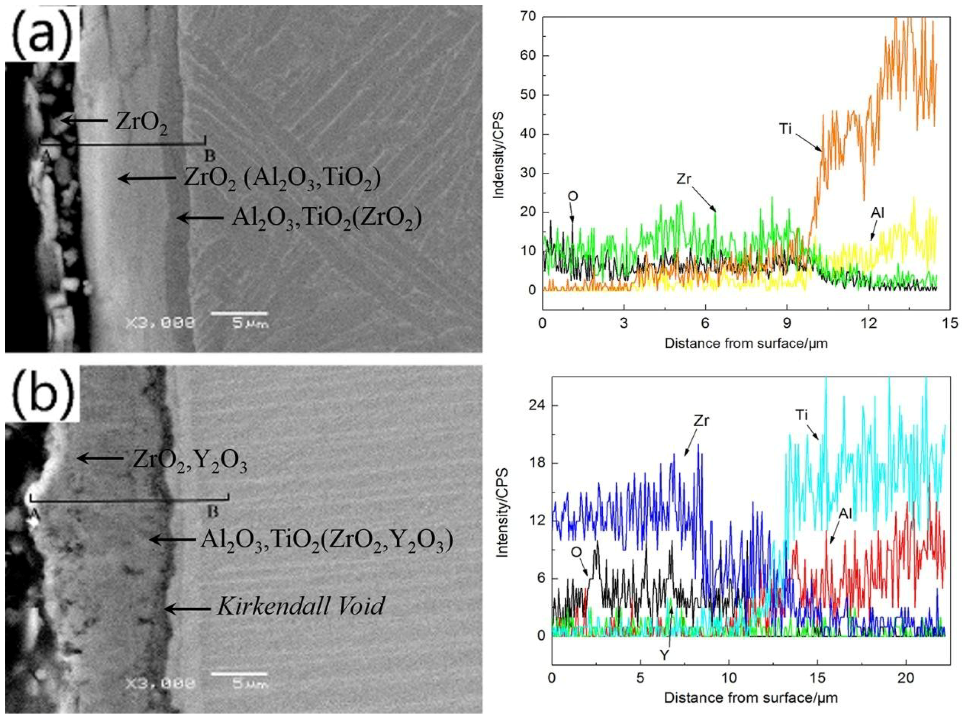
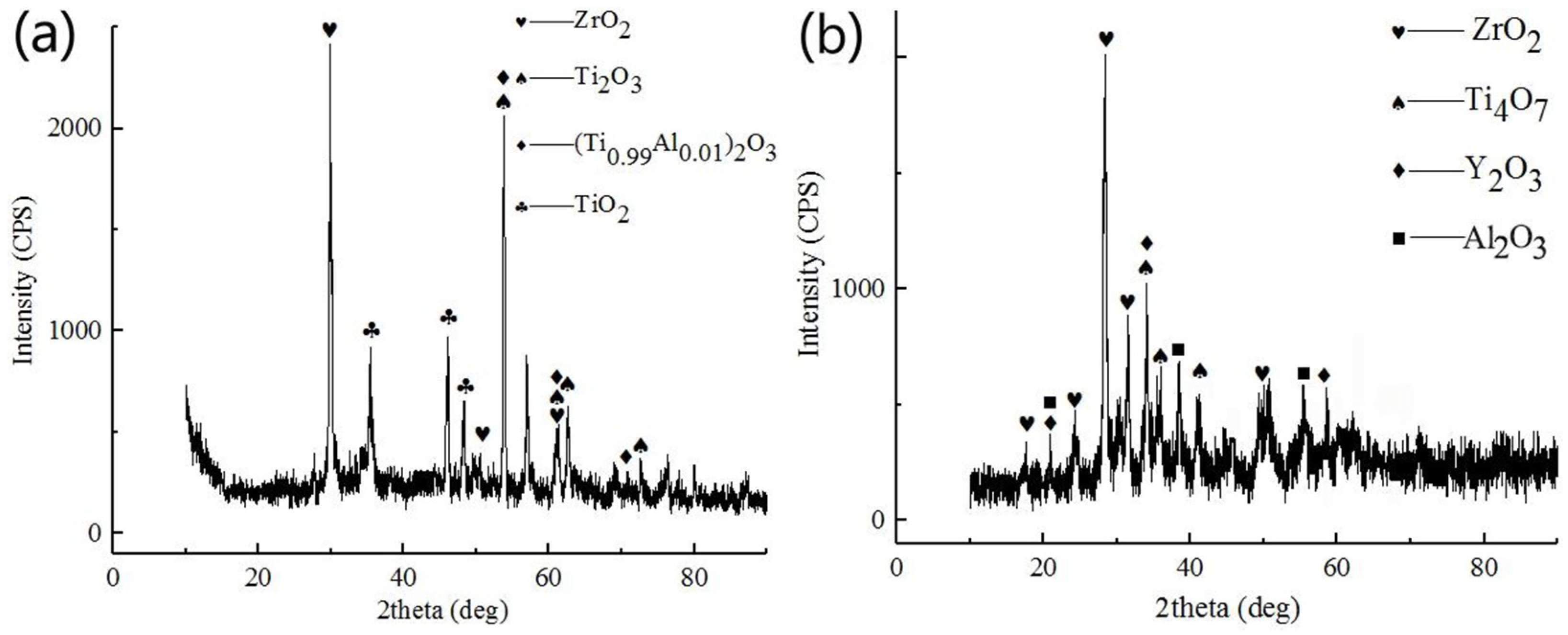
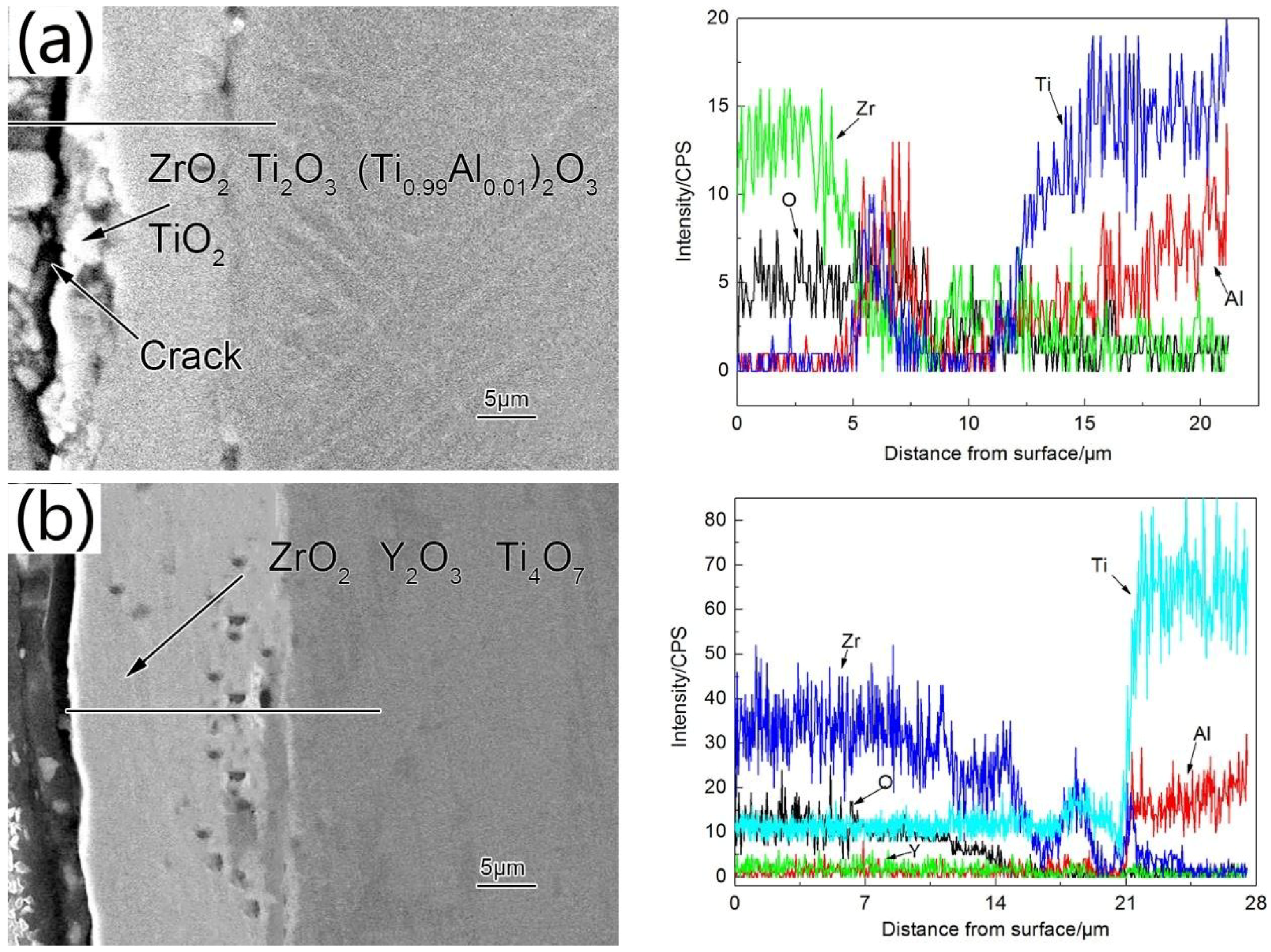
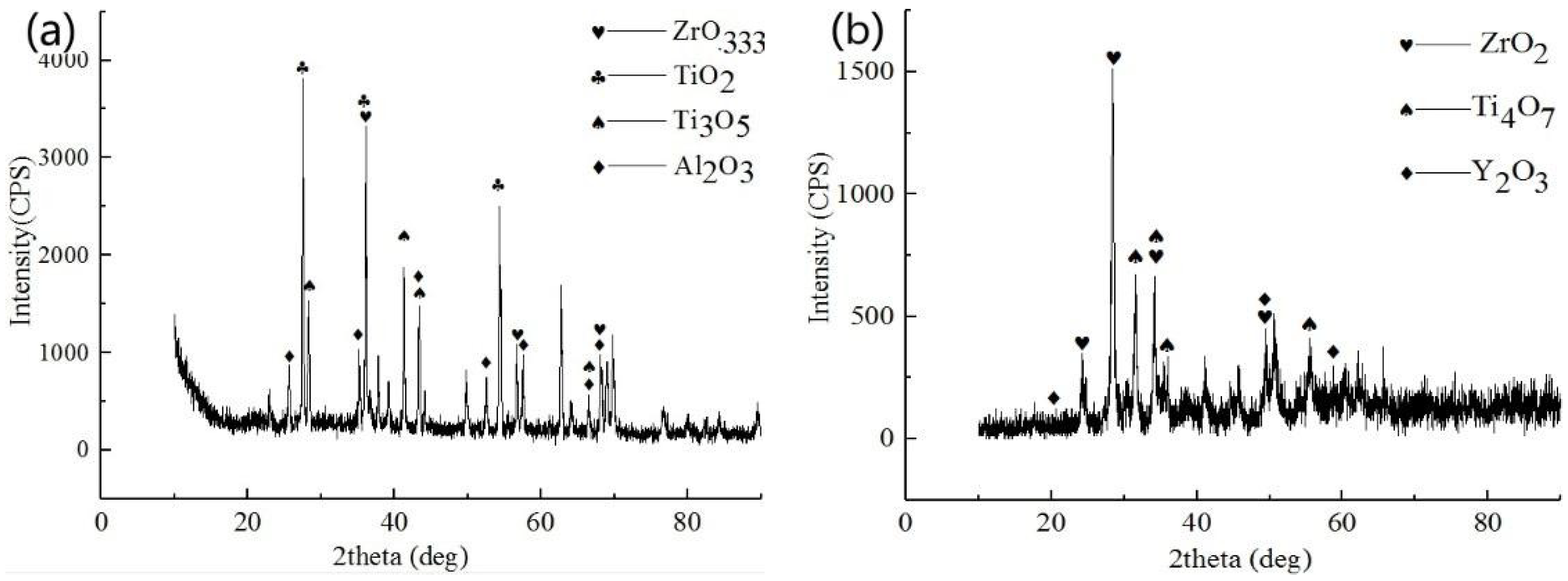
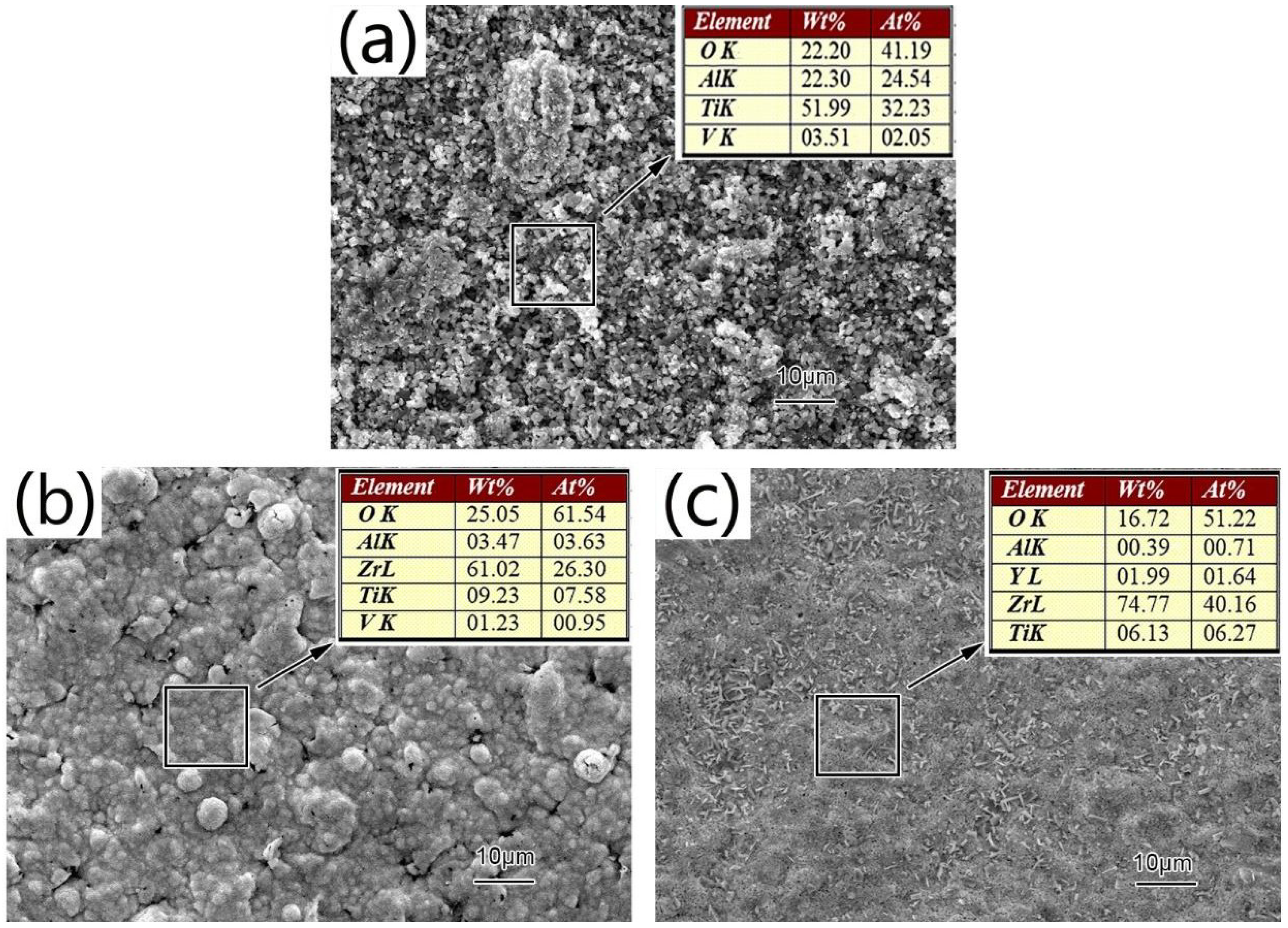
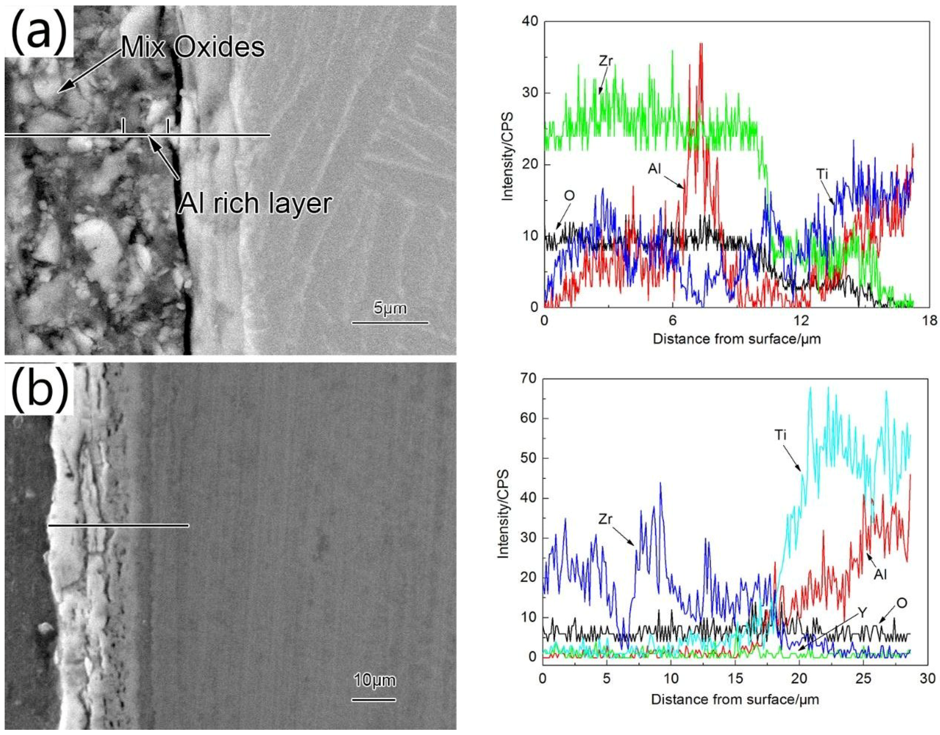
3.2. Structure and Morphologies of the Oxidation Film

The surface of the oxidized Zr coating was mainly composed of ZrO2 and small amounts of TiO2 and Al2O3 (see Figure 5a). TiO2 and Al2O3 diffraction peaks were weaker than that of ZrO2, thus, formation of ZrO2 on the surface of the oxidized film could effectively inhibit TiO2 formation, demonstrating good oxidation resistance. Oxidation products of the Zr-Y coating were mainly ZrO2 Y2O3 and Al2O3, as well as small amount of Ti4O7 (see Figure 5b). No TiO2 was detected. The appearance of Ti4O7 indicated that the Zr and Y elements reacted faster with oxygen preventing it from diffusing into the layer to fully oxidize Ti atoms.
Crystal particles formed during oxidation were large and loosely stacked (see Figure 6a). Oxidation film composed of Al2O3 and TiO2 had very poor adhesion and flaked off easily. Even though some cracks and pores appeared in the oxidized Zr coating (see Figure 6b), a majority of the oxidized film was still in good contact with the substrate, and no peeling was observed. EDS analysis showed only small amounts of TiO2 and Al2O3 in the oxidized film, thus, the oxidized film had good stability and remained continuous, effectively preventing deeper penetration of oxygen. Bubble-like structures were observed on the oxidized Zr-Y coating (see Figure 6c). EDS and XRD demonstrated higher content of Y in these bubbles compared to other regions. The main crystalline phases of the bubbles were ZrO2 and Y2O3. Compared to pure Zr coating, the sizes of oxide particles on Zr-Y coating were more uniform, and the crystals packed tighter without visible cracks or pores. Thus, a compact and continuous oxidation film formed, preventing further oxygen diffusion. Although Y content in Zr-Y coating was only 1.45 wt %, the oxide layer that formed was more protective.
The cross-section diagram shown in Figure 7a demonstrates that the oxidized (at 750 °C for 100 h) Zr coating consisted of three layers. The outer layer was ~3 μm thick, consisted of ZrO2, and was damaged by the stress of the volume expansion associated with the oxidation processes. The intermediate layer consisted of continuous ZrO2 mixed with a small amount of Al2O3 and TiO2. This layer could effectively prevent the deeper penetration of the oxygen since it was very dense without any holes and was tightly bound to the substrate. Contents of O and Zr in the third layer were low, and the main phases in this layer were Al2O3 and TiO2.
No obvious stratification of the oxidized Zr-Y film was observed (see Figure 7b). However, judging by the EDS analysis, it had two layers with different compositions. The outer layer was ~10 μm thick and consisted of ZrO2 and Y2O3 bubble-like oxidized film. The inner layer consisted of Ti4O7 and Al2O3. Due to the thermal stresses and different diffusion rates of metals, Kirkendall voids formed between the oxidized film and the substrate [22]. Al atoms near the substrate diffused into the oxidized film forming amorphous alumina layer under the oxidized film.
Zr coating oxidized at 800 °C consisted of ZrO2 and β-Ti2O3 (see Figure 8a). We believe that β-Ti2O3 formed because the solubility of oxygen in titanium increased with temperature. At the same time, formed ZrO2 hindered diffusion of O. Thus, saturation degree of oxygen in oxides decreased, which facilitated transformation of four-valent titanium in TiO2 to its lower valent states. Al atoms diffused to the outer surface of the alloyed layer and incorporated into the α-Ti2O3 forming (Ti0.99Al0.01)2O3 [1,23].
The main oxidation product of the Zr-Y coating was ZrO2. Contents of all other oxides were much smaller. We believe that Y, distributed at the grain boundaries, oxidized, forming Y2O3 at high temperature, which effectively blocked the diffusion of cations and reduced the overall oxidation rate of the sample. Thus, the oxidation mechanism changed from the bidirectional diffusion of anions and cations to the oxygen diffusion-dominated ones. Oxidation layer formed at the metal-oxidation film interface, producing a small amount of Al2O3 and Ti4O7 [24]. Thus, the oxidation process was stable at this temperature range. The growth rate of titanium oxides in Zr coating was significantly higher than in the Zr-Y coating, thus, Zr-Y coating was more effective in oxidation protection.
As the temperature increased, nucleation rates of the oxide grains on the TiAl surface substrates increased (see Figure 9a). Therefore, grains became smaller and the number of cellular particles decreased. Al content in these cellular particles was above average according to the EDS analysis. The oxidation layer of the Zr coating demonstrated abnormal grain growth and some cracks (see Figure 9b). Therefore, surface defects of Zr-film associated with the oxidation process increased with temperature, diminishing its oxygen blocking effect and further aggravating the oxidation process. However, Zr-Y coating remained relatively intact during the oxidation process mostly because of the formation of fine grains associated with the presence of Y (see Figure 9c). Oxidized Zr-Y coating demonstrated no abnormal grain growths, voids, or cracks. A surface energy spectrum analysis diagram showed only Zr and O as main constituents of the oxidized film. Because Y atoms occupied grain boundaries and other defects, cations in the underlying substrate were effectively prevented from diffusing toward the surface [24,25].
The oxidized layer of the Zr coating formed during annealing at 800 °C for 100 h was ~15 μm and had obvious cracks (see Figure 10a). During the oxidation, the microcracks extended to the edge of the coating (see Figure 9b). Oxidation film eventually separated from the substrate due to the combination of thermal and growth stresses, forming deep longitudinal cracks. These cracks, upon visual inspection of the sample, revealed themselves as a warping of the outside edge of the pores. Cross section of the oxidized Zr-Y coating was smooth without obvious cracks and defects (see Figure 10b). Some scattered small pores were observed. However, they were not dense enough to cause significant damage to the coating. Moreover, these small pores could release thermal stresses and assist in maintaining cohesion and adhesion of the coating at high temperatures. The top layer of the oxidized Zr-Y coating consisted of ZrO2 and a relatively small percentage of Y2O3. Y atoms, uniformly distributed in the coating, oxidized into Y2O3, which then inhibited further oxygen diffusion inside the coating, reducing overall oxidation rate [24,25]. Presence of Y atoms also inhibited upward diffusion of Al atoms, preventing the formation of a poorly crystalline aluminum layer between the coating and the substrate. Thus, addition of only 1.44 wt % of Y played an important role in improving high-temperature oxidation resistance of the coating.
The phase composition of Zr coating after its oxidation at 850 °C was more complex than at other temperatures. It mainly consisted of ZrO0.333 and TiO2 with some small amounts of Al2O3 and Ti3O5 (see Figure 11a). We believe that Zr and O2 reacted first, forming ZrO2. Parts of this ZrO2 underwent polymorphic transformation from monoclinic to tetragonal phase at 850 °C, which led to volume contraction of the oxidized film and formation of a significant amount of micropores and microcracks. As the oxidation process continued, Ti atoms diffused to the surface and reacted with ZrO2, reducing Zr4+ to lower valent states [26].
Oxidation products of Zr-Y coating annealed at 750 °C, 800 °C, and 850 °C for 100 h in air were similar. The only difference was that Al2O3 was not detected after oxidation at 850 °C (see Figure 11b). Formation of Y2O3 stabilized ZrO2, therefore ZrO2 did not undergo polymorphic phase transformation upon cooling to room temperature [27]. Therefore, the coating was stable and dense and provided good protection against oxidation. Y atoms distributed along the grain boundaries hindered diffusion of interior metal ions.
The surface of the oxidized bare γ-TiAl alloy exhibited irregular grains and severe damage when oxidized at 850 °C for 100 h (see Figure 12). Its oxide film was porous and had multiple cracks which are very favorable for oxygen diffusion. These observations can be explained by a disordered crystal structure of TiO2 at high temperatures, especially when comparing to Al2O3. Loose TiO2 particles resulted in poor adhesion of the Al2O3/TiO2 mixed oxidation films. The thermal stresses caused this loose oxidation film to peel from the surface of the substrate at high temperature [28].
The surface of the oxidized Zr coating had more obvious cellular granular growth. The oxidized Zr surface showed numerous deep cracks. As the cracks propagated, the oxidized film started bubbling and peeling off. The outer layer of the oxidized coating was ~10 μm, had loose structures and uneven grain sizes, and completely separated from the substrate. Al concentration was the highest at ~7.5 μm away from the surface (Figure 13a). We believe that diffusion of O, Al and Ti through the intermediate layer led to this complex morphology. Part of the alloy below the oxidized layer contained a lot of dissolved oxygen, leading to severe embrittlement [14]. At 850 °C, oxidation resistance of Zr coating degraded rapidly, and such Zr-coating would not be able to provide adequate protection to the γ-TiAl alloy.
Zr-Y coating remained intact and continuous after its oxidation at 850 °C for 100 h (Figure 13b). Ti and Al contents on the film surface were minor, and the main phases were ZrO2 and Y2O3. The inner layer of the oxidation film was a gradient distribution layer. ZrO2 underwent particle polymorphic transformation at 850 °C. The volume change associated with this polymorph transition affected the oxidized film structure. Because of the similar atomic radii, we believe that a solid solution formed, which explains high solubility of Y2O3 in ZrO2 [25]. The crystal structure of this solid solution changed from monoclinic to tetragonal. Such solid solutions could keep their dual crystal structures without phase transition at both room and high temperatures. Formation of yttria-stabilized ZrO2 is very favorable because it can act as a thermal barrier and has excellent chemical stability, both of which effectively improve high-temperature oxidation resistance of γ-TiAl alloys.

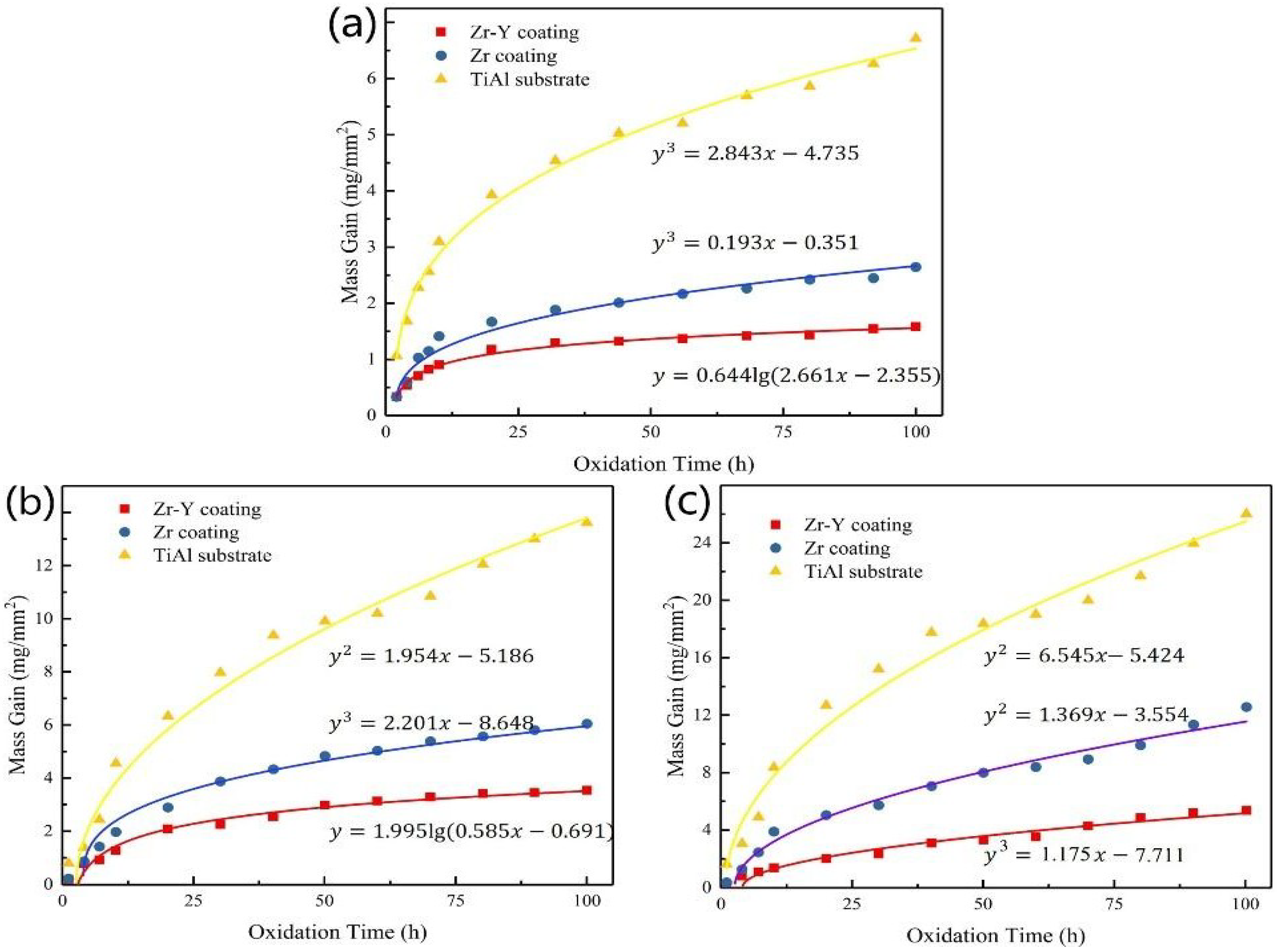
3.3. Isothermal Oxidation Kinetics

Oxidation kinetic curves of bare and Zr and Zr-Y-coated γ-TiAl substrates at 750 °C, 800 °C, and 850 °C are shown in Figure 14. Both coated samples displayed better oxidation resistance than the bare γ-TiAl substrate. Performance of the Zr-Y alloying coating was superior to that of Zr coating.
The rate law of the kinetics curves of the γ-TiAl oxidation reaction changed from cubic to quadratic as the temperature increased. At x = 100, oxidation rates of the γ-TiAl alloy at 750 °C, 800 °C and 850 °C were 0.02216, 0.071 and 0.128 mg/(mm2·h), respectively.
Oxidation kinetics of the Zr coating also followed the cubic law at 700 °C and 800 °C but exhibited a quadratic behavior at 850 °C. At x = 100, oxidation rates of the Zr-coating at 750, 800 and 850 °C were 0.009501, 0.0206 and 0.059 mg/(mm2·h), respectively. At lower oxidation temperatures, relatively continuous oxidation layers formed. Oxygen diffusion was restricted by many factors but especially by the formation of the dense oxidation layer. Oxygen mainly diffused from the grain boundaries. At 850 °C, the crystal structure of some ZrO2 crystals changed, which damaged the film and could no longer restrict oxygen diffusion. High-temperature oxidation resistances of Zr coating at 750 °C, 800 °C and 850 °C were 2.3, 3.4 and 2.2 times higher than that of the bare substrate, respectively.
Oxidation kinetics of the Zr-Y coating followed the logarithmic rate law at 700 °C and 800 °C and cubic rate law at 850 °C. At x = 100 h, the oxidation rates at 750 °C, 800 °C and 850 °C were 0.002822, 0.008729 and 0.0145 mg/(mm2·h), respectively. Zr-Y oxidized film was dense due to the compressive stresses at 700 °C and 800 °C. Y atoms were distributed along the grain boundaries, preventing metal ions from diffusing toward the surface and slowing down the oxygen diffusion into the coating. At 850 °C, monoclinic phases in the oxidation layer partially transformed to tetragonal, causing volume shrinkage and reduction of the compressive stresses, which led to even further densification of the oxidized film. Therefore, high-temperature oxidation resistance of Zr-Y coating increased at 850 °C. Addition of Y stabilized ZrO2 making the oxidized film continuous and minimally damaged. High-temperature oxidation resistance of Zr-Y coating at 750 °C, 800 °C and 850 °C was 7.9, 8.1 and 8.8 times higher than the corresponding values of the bare TiAl alloy, respectively. It was also 3.4, 2.4, and 4.1 times higher compared to that of Zr coating, respectively.

4. Conclusions

We used double-glow plasma surface alloying technology to coat γ-TiAl alloy with Zr and Zr-Y alloying coatings. SEM morphologies demonstrated metallurgically bonded coatings without any defects.
Bare γ-TiAl alloy demonstrated abnormal grain growth, and, as a result, poor oxidation resistance. Oxidation products of the Zr coating mainly consisted of ZrO2 at 750 °C and 800 °C. The oxidation film was intact at these temperatures. At 850 °C, monoclinic ZrO2 underwent partial phase transformation causing cracking. Some Ti atoms diffused through these cracks towards the surface and formed complex oxides. Thus, such highly degraded Zr coating could not provide adequate oxidation resistance.
High-temperature oxidation resistance of Zr-Y alloying coating was better than that of γ-TiAl and Zr coating at all temperatures tested. Presence of Y atoms effectively prevented O and Ti diffusion. Y atoms refined the grains and also stabilized ZrO2 crystal structure, making oxidized film continuous and undamaged.
All three samples tested (bare and Zr- and Zr-Y-coated TiAl alloys) showed different types of oxidation kinetics at different temperatures indicating different oxidation mechanisms. High-temperature oxidation resistance of Zr-Y coating at 750 °C, 800 °C and 850 °C was 7.9, 8.1 and 8.8 times higher than that of the uncoated substrate, respectively. It was 3.4, 2.4, and 4.1 times higher than that of Zr coating, respectively.

Author Contributions

Conceptualization, F.D. and P.Z., Z.W.; Methodology, D.W., Z.W.; Validation, P.Z.; Formal Analysis, F.D., X.C., S.W.; Investigation, F.D., Y.Z.; Resources, P.Z., Z.W. and D.W.; Data Curation, Y.Z. and F.D.; Writing—Original Draft Preparation, Y.Z. and F.D.; Writing—Review & Editing, X.C., S.W.; Visualization, D.W.; Supervision, P.Z. and Z.W.; Project Administration, P.Z. and Z.W.

Funding

The work was funded by the Priority Academic Program Development of Jiangsu Higher Education Institutions, the Jiangsu Province Graduate Cultivation Innovative Project (No. KYLX16_0347), the China Postdoctoral Science Foundation funded project (No. 2018M630555), the Fundamental Research Funds for the Central Universities (No. NS2018039), the Natural Science Foundation for Young Scientists of Jiangsu Province (No. BK20140819), the Aeronautical Science Foundation of China (No. 2016ZF52056), the China Scholarship Council (No. 201706830071, award to Xiaohu Chen for 1 year’s study at the Carleton University) and Natural Science Foundation for Excellent Young Scientists of Jiangsu Province, China (No. BK20180068).

Acknowledgments

Thanks to Xiaoxin Wei for the SEM pictures.

Conflicts of Interest

The authors declare no conflicts of interest.

References

  1. Leyens, C.; Peters, M. Titanium and Titanium Alloys; John Wiley & Sons: Hoboken, NJ, USA, 2003. [Google Scholar]
  2. Braun, R.; Fröhlich, M.; Leyens, C.; Renusch, D. Oxidation Behaviour of TBC Systems on gamma-TiAl Based Alloy Ti-45Al-8Nb. Oxid. Met. 2009, 71, 295–318. [Google Scholar] [CrossRef]
  3. Kumpfert, J.; Kim, Y.W.; Dimiduk, D.M. Effect of microstructure on fatigue and tensile properties of the gamma TiAl alloy Ti-46.5Al-3.0Nb-2.1Cr-0.2W. Mater. Sci. Eng. A 1995, 192–193, 465–473. [Google Scholar] [CrossRef]
  4. Dettenwanger, F.; Schumann, E.; Ruhle, M.; Rakowski, J.; Meier, G. Microstructural Study of Oxidized γ-TiAl. Oxid. Met. 1998, 50, 269–307. [Google Scholar] [CrossRef]
  5. Yoshihara, M.; Kim, Y.W. Oxidation behavior of gamma alloys designed for high temperature applications. Intermetallics 2005, 13, 952–958. [Google Scholar] [CrossRef]
  6. Allen, S.M.; Pelloux, R.M.; Widmer, R. Advanced High-Temperature Alloys: Processing and Properties; American Society for Metals: Metals Park, OH, USA, 1986. Available online: http://www.osti.gov/scitech/servlets/purl/6718810 (accessed on 2 October 2018).
  7. Brady, M.P.; Brindley, W.J.; Smialek, J.L.; Locci, I.E. The oxidation and protection of gamma titanium aluminides. JOM 1996, 48, 46–50. [Google Scholar] [CrossRef] [Green Version]
  8. Chu, P.K. Progress in direct-current plasma immersion ion implantation and recent applications of plasma immersion ion implantation and deposition. Surf. Coat. Technol. 2013, 229, 2–11. [Google Scholar] [CrossRef]
  9. Zhang, X.J.; Li, Q.; Zhao, S.Y.; Gao, C.X.; Wang, L.; Zhang, J. Improvement in the oxidation resistance of a γ-TiAl-based alloy by sol-gel derived Al₂O₃ film. Appl. Surf. Sci. 2008, 225, 1860–1864. [Google Scholar] [CrossRef]
  10. Ait-Djafer, A.Z.; Saoula, N.; Aknouche, H.; Guedouar, B.; Madaoui, N. Deposition and characterization of titanium aluminum nitride coatings prepared by RF magnetron sputtering. Appl. Surf. Sci. 2015, 350, 6–9. [Google Scholar] [CrossRef]
  11. Brady, M.P.; Smialek, J.L.; Humphrey, D.L.; Smith, J. The role of Cr in promoting protective alumina scale formation by γ-based Ti_Al_Cr alloys—II. Oxidation behavior in air. Acta Mater. 1997, 45, 2371–2382. [Google Scholar] [CrossRef]
  12. Schiller, S.; Goedicke, K.; Reschke, J.; Kirchhoff, V.; Schneider, S.; Milde, F. Pulsed magnetron sputter technology. Surf. Coat. Technol. 1993, 61, 331–337. [Google Scholar] [CrossRef]
  13. Thiele, E.S.; Wang, L.S.; Mason, T.O.; Barnett, S.A. Deposition and properties of yttria-stabilized zirconia thin films using reactive direct current magnetron sputtering. J. Vac. Sci. Technol. A Vac. Surf. Films 1991, 9, 3054–3060. [Google Scholar] [CrossRef]
  14. Musil, J.; Poláková, H. Hard nanocomposite Zr-Y-N coatings, correlation between hardness and structure. Surf. Coat. Technol. 2000, 127, 99–106. [Google Scholar] [CrossRef]
  15. Salvadori, M.C.; Teixeira, F.S.; Sgubin, L.G.; Cattani, M.; Brown, I.G. Surface modification by metal ion implantation forming metallic nanoparticles in an insulating matrix. Appl. Surf. Sci. 2014, 310, 158–163. [Google Scholar] [CrossRef] [Green Version]
  16. Conrad, J.R.; Radtke, J.L.; Dodd, R.A.; Worzala, F.J.; Tran, N.C. Plasma source ion-implantation technique for surface modification of materials. J. Appl. Phys. 1987, 62, 4591–4596. [Google Scholar] [CrossRef]
  17. Luo, X.X.; Yao, Z.J.; Zhang, P.Z.; Miao, Q.; Liang, W.P.; Wei, D.B.; Chen, Y. A study on high temperature oxidation behavior of double glow plasma surface metallurgy Fe-Al-Cr alloyed layer on Q235 steel. Appl. Surf. Sci. 2014, 305, 259–266. [Google Scholar] [CrossRef]
  18. Wei, D.; Zhang, P.; Yao, Z.; Zhou, J.; Wei, X.; Chen, X. Double glow plasma chromizing of Ti6Al4V alloys: Impact of working time, substrate-target distance, argon pressure and surface temperature of substrate. Vacuum 2015, 121, 81–87. [Google Scholar] [CrossRef]
  19. Zhang, P.; Xu, Z.; Zhang, G.; He, Z. Surface plasma chromized burn-resistant titanium alloy. Surf. Coat. Technol. 2007, 201, 4884–4887. [Google Scholar] [CrossRef]
  20. Xu, Z.; Liu, X.; Zhang, P.; Zhang, Y.; Zhang, G.; He, Z. Double glow plasma surface alloying and plasma nitriding. Surf. Coat. Technol. 2007, 201, 4822–4825. [Google Scholar] [CrossRef]
  21. Birks, N.; Meier, G.H.; Pettit, F.S. Introduction to the High Temperature Oxidation of Metals; Cambridge University Press: Cambridge, UK, 2006. [Google Scholar]
  22. Brady, M.P.; Sachenko, P. Effects of Fe on the oxidation/internal nitridation behavior and tensile properties of Cr and oxide dispersion ductilized Cr. Scr. Mater. 2005, 52, 809–814. [Google Scholar] [CrossRef]
  23. Wanjara, P.; Jahazi, M.; Monajati, H.; Yue, S.; Immarigeon, J.P. Hot working behavior of near-α alloy IMI834. Mater. Sci. Eng. A 2005, 396, 50–60. [Google Scholar] [CrossRef]
  24. Fuhui, W.; Hanyi, L.; Linxiang, B.; Weitao, W. Hot corrosion of yttrium-modified aluminide coatings. Mater. Sci. Eng. A 1989, 120–121, 387–389. [Google Scholar] [CrossRef]
  25. Zhou, W.; Zhao, Y.G.; Li, W.; Tian, B.; Hu, S.W.; Qin, Q.D. Oxidation behavior of the Y₂O₃-modified aluminide coating on Ti-6Al-4V alloy. Mater. Sci. Eng. A 2007, 458, 34–38. [Google Scholar] [CrossRef]
  26. Wang, L.D.; Wang, Y.H.; Li, W.Z.; Li, H.D.; Takeo, O.K. Reaction behaviour of ZrO₂/Ti interface injointing zirconia ceramics and stainless steel 304 with Ti foil. Acta Metall. Sin. 1997, 7, 756–762. [Google Scholar]
  27. Chen, Y.; Kong, F.; Han, J.; Chen, Z.; Tian, J. Influence of yttrium on microstructure, mechanical properties and deformability of Ti-43Al-9V alloy. Intermetallics 2005, 13, 263–266. [Google Scholar] [CrossRef]
  28. Kim, B.G.; Kim, G.M.; Kim, C.J. Oxidation behavior of TiAl-X (X = Cr, V, Si, Mo or Nb) intermetallics at elevated temperature. Scr. Metall. Mater. 1995, 33, 1117–1125. [Google Scholar] [CrossRef]
Figure 1. Schematic diagram of the double glow plasma surface alloying technique.
Coatings 08 00361 g001
Figure 2. SEM morphologies and surface chemical composition of the alloying coatings: (a) Zr; (b) Zr-Y.
Coatings 08 00361 g002
Figure 3. Component distribution of the Zr-Y coating: (a) cross-section; (b) EDS.
Coatings 08 00361 g003
Figure 4. XRD pattern of the Zr-Y coating.
Coatings 08 00361 g004
Figure 5. XRD pattern of the specimens at 750 °C for 100 h: (a) Zr coating; (b) Zr-Y coating.
Coatings 08 00361 g005
Figure 6. Surface morphology and EDS pattern of specimens at 750 °C for 100 h: (a) TiAl substrate; (b) Zr coating; (c) Zr-Y coating.
Coatings 08 00361 g006
Figure 7. Cross-sectional morphologies and compositions of the specimens at 750 °C for 100 h: (a) Zr coating; (b) Zr-Y coating.
Coatings 08 00361 g007
Figure 8. XRD patterns of the specimens at 800 °C for 100 h: (a) Zr coating; (b) Zr-Y coating.
Coatings 08 00361 g008
Figure 9. Surface morphology and EDS pattern of specimens at 800 °C for 100 h: (a) TiAl substrate; (b) Zr coating; (c) Zr-Y coating.
Coatings 08 00361 g009
Figure 10. Cross-sectional morphologies and compositions of the specimens at 800 °C for 100 h: (a) Zr coating; (b) Zr-Y coating.
Coatings 08 00361 g010
Figure 11. XRD pattern of the specimens at 850 °C for 100 h: (a) Zr coating; (b) Zr-Y coating.
Coatings 08 00361 g011
Figure 12. Surface morphology and EDS pattern of specimens at 850 °C for 100 h: (a) TiAl substrate; (b) Zr coating; (c) Zr-Y coating.
Coatings 08 00361 g012
Figure 13. Cross-sectional morphologies and compositions of the specimens at 850 °C for 100 h: (a) Zr coating; (b) Zr-Y coating.
Coatings 08 00361 g013
Figure 14. Oxidation kinetics of the specimens at (a) 750 °C; (b) 800 °C; (c) 850 °C.
Coatings 08 00361 g014
Table 1. Chemical composition of γ-TiAl (wt %).
TiAlVCrNbOCN
The rest46.5≤1.5≤1≤0.20≤0.01≤0.1≤0.05
Table 2. Process parameters of plasma surface alloying.
ParametersValue
Source voltage/V600–650
Cathode voltage/V450–500
Processing time/h3
Work-piece pressure/Pa36
Processing temperature/°C900–950
Distance between source and cathode/mm18

