Improvement of Corrosion Protection of Coating System via Inhibitor Response Order


School of Materials Science and Engineering, Beihang University, Beijing 100191, China
*
Author to whom correspondence should be addressed.
Coatings 2018, 8(10), 365; https://doi.org/10.3390/coatings8100365
Submission received: 29 August 2018
/
Revised: 30 September 2018
/
Accepted: 15 October 2018
/
Published: 16 October 2018
Abstract
:This study aims at investigating the effect of inhibitor response order on anticorrosion properties of AA2024 with coating system. The inhibitor response order was constructed by adding different inhibitor in sol-gel primer or epoxy top coating of the coating system. Nanocontainers of graphene oxide/layered double hydroxides (GO/LDHs) were loaded with 2-mercaptobenzothiazole (MBT) and vanadate separately to get the inhibitors of GO/LDHs-MBT and GO/LDHs-VOx, which were used in this work. The protection performances of the coating systems with different inhibitor combination and different inhibitor response order were investigated. The best protective coating system is composed of sol-gel coating with GO/LDHs-MBT and epoxy coating with GO/LDHs-VOx. It is contributed to inhibitor combination and a proper response order of the inhibitors. When filiform corrosion occurs, MBT anions from the sol-gel coating are close to the alloy and they inhibit the corrosion in anodic areas immediately, and then vanadate anions from the out and thick epoxy coating reduce the kinetics of the cathodic oxygen reduction reaction. Response order enhances the corrosion protection properties provided by inhibitor combination, which gives a promising way to design good anticorrosive coating system.
1. Introduction
Protective organic coatings are one of the most important approaches to protect metals against corrosion, and coatings with both passive and active protection are drawing attention [1]. One strategy to get active protection is adding corrosion inhibitors into coatings [2,3,4].
Additionally, inhibitor combination is a constructive way to improve active protection of the metals [5,6,7,8,9]. Kallip et al. reported 1,2,3-Benzotriazole (BTA) and Ce(NO3)3 as an inhibiting mixture for corrosion inhibition of Zn + Fe model galvanic couple. It was demonstrated that adsorption based anodic inhibitor BTA and the cathodic inhibitor Ce(NO3)3 had a superior synergistic inhibition effect [7]. Zhang et al. investigated the inhibition effect of rare earth cerium nitrate (Ce(NO3)3) and sodium dodecylbenzenesulfonate (DBS) on corrosion of AA5052 aluminium alloy. The results showed that the single Ce(NO3)3 or DBS had a limited inhibition effect against corrosion of AA5052 alloy. However, the combination cerium ions with DBS produced a strong synergistic effect on corrosion inhibition for AA5052 alloy, for the formation of the complex of Al(DBS)3 and Ce(DBS)3 stabilized the passive film of Al2O3 and CeO2 [10]. Snihirova et al. studied the inhibition efficiency of inhibitors (Ce3+, 8-hydroxyquinoline (8HQ), salicylaldoxime (SAL), and 2,5-dimercapto-1,3,4-thiadiazolate (DMTD)) for AA2024 in NaCl solution and epoxy coating, containing a single inhibitor or a mixture of inhibitors. 8HQ and SAL adsorbed on surface forming a thin film, and DMTD formed precipitates or adsorbates on intermetallic particles in AA2024. These interactions were good to inhibit the corrosion process. They found that corrosion protection was further improved by mixing two inhibitors, and the corrosion protection properties of inhibitor combination added in coatings cannot be directly predicted from results of that added in solution [11]. Garcia et al. reported the corrosion inhibition synergy of Ce3+ and 2-Mercaptobenzothiazole loaded in zeolite and layered double hydroxide, respectively. The combination of the inhibitor doped containers improved the active protection of the substrate, confirming the synergy between the two inhibitor doped containers [12]. Saei et al. combined organic inhibitor (polyvinyl alcohol) and inorganic inhibitors (Mn(NO3)2·4H2O, Co(NO3)2·6H2O) and studied their effects on the nanostructure cerium based conversion coating. Results demonstrated that the alloy sample that was treated by Ce-Mn-PVA. showed the highest corrosion resistance [13].
Inhibitor combination enhances the corrosion protection properties commonly by providing a synergistic effect, such as anodic and cathodic inhibition, from different inhibitors. The positive effect is usually verified by combination in solution or in single coating layer. However, most of metals are coated with multilayered coatings in practice, and the corrosion processes are complex. The position of inhibitors in the coating system would influence their response to corrosion. Thus, the effect of inhibitor combination and position in coating system on the corrosion protection is interesting to be explored.
Hybrid materials based on graphene are becoming more common in the scientific literature about coatings. They influence thermal, mechanical, electrical, and functional properties of numerous coating systems [14,15,16]. In our recent study, it was shown that graphene oxide/layered double hydroxides (GO/LDHs) were able to encapsulate inhibitors MBT and vanadate by anion exchange reaction [17]. When incorporated into coatings, GO/LDHs showed good dispersion and controlled the release of inhibitors, which enhanced the corrosion protection properties of the coating. Hence, the GO/LDHs were chosen as nanocontainers to encapsulate the corrosion inhibitors MBT (GO/LDHs-MBT) and vanadate (GO/LDHs-VOx) in this work. GO/LDHs-MBT and GO/LDHs-VOx were added in sol-gel coating or epoxy coating to construct six different coating systems with different inhibitor combination and inhibitor response order. The corrosion inhibition properties that were provided by inhibitor combination on AA2024 were investigated in solution and coating system through electrochemical impedance spectroscopy measurement and salt spray test. The effect of inhibitor response order on the protection performances was further studied and analyzed.
2. Experimental
2.1. Materials
Aluminum nitrate (Al(NO3)3·9H2O), zinc nitrate (Zn(NO3)2·6H2O), sodium nitrate (NaNO3), and sodium hydroxide (NaOH) were purchased by Beijing Chemical Works, Beijing, China. Precursors of the hybrid sol-gel coating included 3-glycidoxypropylmethyldiethoxysilane (GPTMS) that was purchased from J&K, Beijing, China and zirconium n-propoxide (TPOZ) purchased from Strem Chemicals, Newburyport, MA, USA. Anhydrous ethanol and acetyl ethyl acetate were obtained from Beijing Chemical Works. Epoxy resin (E51) (epoxy equivalent was 0.48 mol/100 g) and polyamide curing agent HB-125 were purchased from Zhenjiang Danbao Resin Co. Ltd., Zhenjiang, Jiangsu, China. Natural graphite flake were purchased from Beijing Chemical Works.
2.2. Nanocontainers Preparation and Inhibitor Loading
Nanocontainers GO/LDHs were prepared and encapsulated inhibitors, as described in our previous work [17]. In short, the nanocontainers GO/LDHs composed of GO and LDHs was synthesized via a co-precipitation method, and then loaded with inhibitors 2-mercaptobenzothiazole (GO/LDHs-MBT) and vanadate (GO/LDHs-VOx) via anion exchange reaction.
2.3. Coating System Preparation
The AA2024 samples, with a dimension of 50 mm × 40 mm × 3 mm, were ground to 2000 grades using sandpaper. After that, the grounded samples were cleaned in an alkaline aqueous solution (0.5 wt.% NaOH, 1 wt.% Na2CO3 and 2 wt.% Na3PO4) at 50 °C for 1 min, washed with deionized water, acid etched in 400 g/L nitric acid, then rinsed with deionized water, and dried in order.
The cleaned samples were coated with a sol-gel coating and then an epoxy coating. The sol solution formulation and coating preparation were described in detail elsewhere [17]. Briefly, nanofillers (GO/LDHs-MBT or GO/LDHs-VOx) were dispersed in aqueous solution by stirring and sonication. Silica sol was made of ethanol, aqueous solution containing nanofillers, and GPTMS in 4:2:3 volume ratio. Zircon sol was composed of ethanol, ethyl acetoacetate, and TPOZ in 2:1.2:2 volume ratio. The two sol solutions were separately hydrolyzed for 1 h with stirring, and then mixed and adjusted pH to 4.0 ± 0.2 by diluted nitric acid. The final sol was obtained by stirring at room temperature for 2 h. The concentration of nanofillers was about 0.5 wt.% in final sols.
A sol-gel coating was prepared by the dipping method. The cleaned samples were immersed in the sol solution for 5 min, then removed at the speed of 100 mm/min and placed in air for 15 min. This operation was repeated twice. The dip-coated samples were orderly cured at 60 °C for 60 min, 90 °C for 30 min, and 110 °C for 15 min. The cured samples were stored in a glass vacuum desiccator for 12 h before being coated with an epoxy coating.
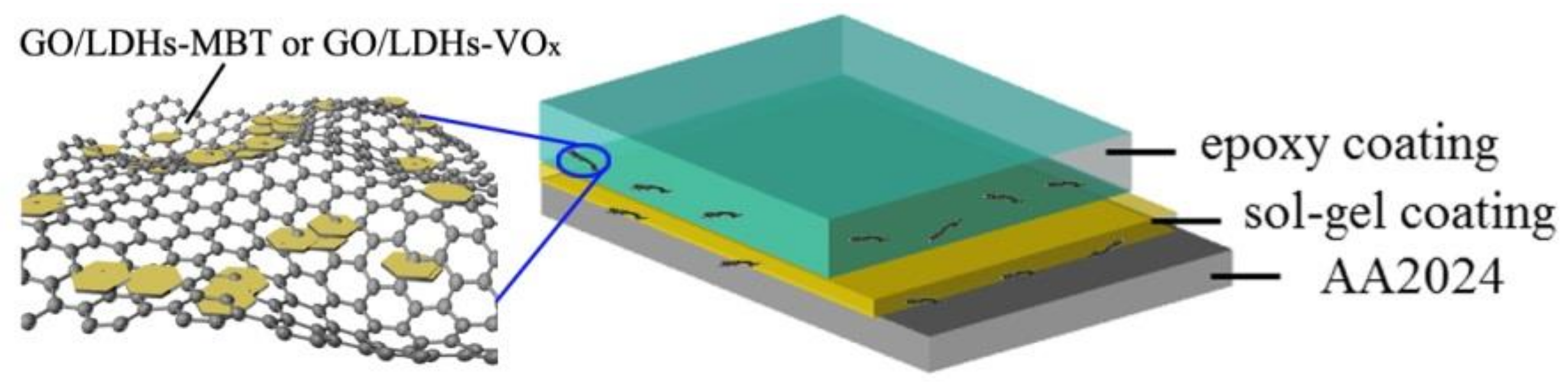
The solvent of epoxy resin was a mixture of dimethylbenzene and n-butyl alcohol in 7:3 volume ratios. After being rinsed by ethanol, 0.5 g nanofillers (GO/LDHs-MBT, GO/LDHs-VOx or GO/LDHs-MBT + GO/LDHs-VOx) were ultrasonically dispersed in 50 ml solvent, respectively, and 50 g epoxy resin was added to the mixture (epoxy resin:nanofillers = 100:1 wt.%). The resin and the nanofillers were uniformly mixed via stirring and sonication and HB-125 added as a curing agent into the mixture (resin:curing agent = 2:1 wt.%). Then, the mixture was stirred and shaken to obtain a uniform solution. The sol-gel coating coated alloys were immersed in this solution for 2 min, pulled up at a speed of 20 mm/min, kept in the air for 15 min, and cured at 30 °C for 24 h. The schematic diagram of the prepared coating system was drawn in Figure 1. Different coating systems with combinations of GO/LDHs-MBT and GO/LDHs-VOx in sol-gel and epoxy coatings were prepared. The six types of coating systems prepared and tested were summarized in Table 1.
2.4. Characterization
The morphology of GO/LDHs, GO/LDHs-MBT, and GO/LDHs-VOx was characterized by scanning electron microscopy (SEM; JSM-7500, JEOL, Tokyo, Japan) and transmission electron microscopy (TEM; JSM-2100F, JEOL, Tokyo, Japan). X-ray photoelectron spectroscopy (XPS; Thermo Scientific Escalab 250Xi, Fischer, Waltmen, MA, USA) was used to analyze the composition and chemical structure of GO/LDHs, GO/LDHs-MBT, and GO/LDHs-VOx. The crystal structures of them were investigated by X-ray diffraction (XRD; D-AMX2500, Rigaku, Tokyo, Japan). The structures of them were characterized by Fourier transform infrared spectrometer (FTIR; Nicolet iS10, Fischer). The surface morphology of the coatings was characterized by SEM. The thickness of the cured coatings was measured by a coating thickness measurement instruments (Fischer).
Corrosion inhibition of nanofillers (GO/LDHs-MBT, GO/LDHs-VOx, and a mixture of GO/LDHs-MBT + GO/LDHs-VOx, respectively) with regard to AA2024 was characterized by electrochemical impedance spectroscopy (EIS) and surface observation. The cleaned substrates were immersed in a 0.05 M NaCl solution and 0.05 M NaCl solution containing nanofillers. The concentration of the nanofillers in solution was 5 g/L (the one of each constituent was 2.5 g/L in the GO/LDHs-MBT + GO/LDHs-VOx mixture). 0.05M NaCl solution was used for the bare substrates and the scratched samples, which aims to decrease rate of corrosion and allow for more correct estimation of the inhibition for corrosion at the early stages [18].
The corrosion protection of coatings was measured by EIS. The measurements were conducted on an electrochemical workstation (Parstat 2273, Princeton, NJ, USA). The used three-electrode system was consisted of a saturated calomel electrode (SCE, reference electrode), a platinum plate counter electrode and the prepared samples as working electrode. It was placed in a Faraday cage. The electrolyte was a 3.5 wt.% NaCl solution. The frequency range selected for EIS was from 100 kHz to 10 mHz, and the amplitude of the sinusoidal voltage was 20 mV at open circuit potential (OCP). The software Zview was used to fit the experimental data with different equivalent circuits. The salt spray tests were conducted to evaluate the corrosion protection of coatings according to the ASTM B117 standard [19].
3. Results and Discussion
3.1. Characterization of Nanofillers
In our previous work, we characterized the morphology and structure of the GO/LDHs in detail [17]. Briefly, the GO/LDHs display characteristic diffractions of hydrotalcite-like materials [20], indicating the existence of LDHs (Figure 2a). The characteristic peaks of GO/LDHs-MBT and GO/LDHs-VOx are lower than that of GO/LDHs, which is related to the intercalated MBT anions or vanadate anions, which have a larger size in dimension than NO3− [21]. In FTIR spectra (Figure 2b), GO was co-precipitated in GO/LDHs, GO/LDHs-MBT, and GO/LDHs-VOx. The peaks below 1000 cm−1 are due to Zn2+-OH or Al3+-OH stretching vibrations of LDHs phase. After anion exchange, the two peaks of NO3− (1358 cm−1 and 1390 cm−1) convolute into one peak at 1362 cm−1 and the intensity decreases, indicating a distinct reduction of NO3− [17]. Moreover, several new peaks that were present in the GO/LDHs-MBT, which can be ascribed to different vibrations of the exchanged MBT anions. The characteristic peak at 785 cm−1 in the GO/LDHs-VOx arises from the exchanged vanadate anions.
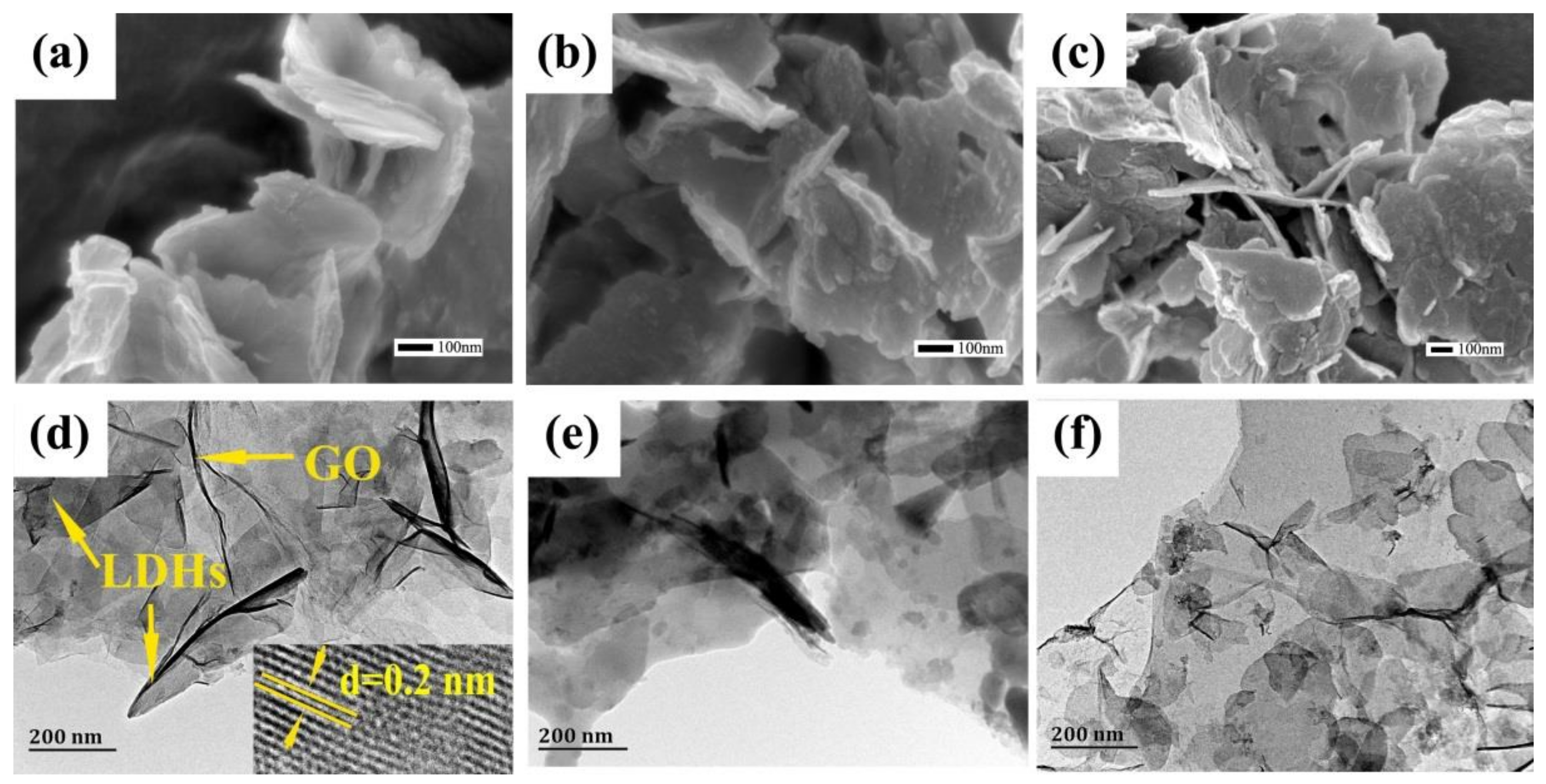
The GO/LDHs (Figure 3a) exhibit a loose curved lamellar morphology without obvious agglomeration. Most of the LDHs, size varied from 100 to 300 nm, are face upward and parallel to the underlying GO, acting as a support (Figure 3d). After anion exchange, GO/LDHs-MBT (Figure 3b,e) and GO/LDHs-VOx (Figure 3c,f) maintain the loose curved lamellar morphology, like GO/LDHs. It is demonstrated that nanocontainers GO/LDHs were synthesized and encapsulated with MBT anions and vanadate anions through anion exchange.
XPS was carried out to obtain more information about the chemical structure of GO/LDHs, GO/LDHs-MBT and GO/LDHs-VOx. Evidently, the spectra (Figure 4a) of GO/LDHs, GO/LDHs-MBT, and GO/LDHs-VOx exhibit C 1s peak, O 1s peak, and two peaks at 74.3 and 1021.7 eV, which are attributed to Al 2p and Zn 2p, respectively. These peaks confirm the existence of LDHs in GO/LDHs once again, which is in agreement with the result of XRD. Furthermore, the spectrum of GO/LDHs-MBT depicts N 1s peak and S 2p peak, and the one of GO/LDHs-VOx depicts V 2p.
The C 1s XPS spectrum (Figure 4b) of GO/LDHs is deconvoluted into three doublets: non-oxygenated ring contexts C–C (284.75 eV), C–O (286.5 eV), and O–C=O (288.9 eV) [22]. The result clearly shows the presence of GO. Among the three parts of C 1s, the area of the non-oxygenated ring contexts in the GO/LDHs is about 72.3% (284.75 eV), while that of GO is about 45%. These results indicate that most of the oxygen functional groups of GO are removed in the GO/LDHs [22]. It is further verified that GO serves as a support and the oxygen functional groups on it act as nucleation sites for the growth of LDHs [23].
There are two differently S atoms in the MBT: endocyclic (–S–) and exocyclic (=S) sulfur. It is meaning that there are at least two doublets in the XPS spectrum. In the S 2p XPS spectrum (Figure 4d) of GO/LDHs-MBT, the doublet at 162.6 eV is assigned to exocyclic sulfur, and the doublet at 164.0 eV is assigned to endocyclic sulfur [24,25], the one at 165.1 eV is from sulphoxides (>R=O) [26]. The results show that MBT anions were successfully loaded in GO/LDHs-MBT. Based on the peak area, the ratio of the chemisorbed sulfur and the endocyclic sulfur is 1:1.89. Only one chemical state for V 2p of GO/LDHs-VOx is obtained from deconvolution of V 2p at 517.23 eV (Figure 4e). It is assigned to vanadium in five valent (V5+) [27]. During the anion exchange reaction, the pH of the vanadate-containing solution was about 8.4. On this condition, the main species of vanadate anions are V2O74− and HV2O73− [17,21]. So, the existence of vanadium (V5+) confirms vanadate anions in GO/LDHs-VOx.
3.2. Corrosion Inhibition Properties of Inhibitor Mixture
EIS curves of the AA2024 samples after immersion in different solutions for two days are shown in Figure 5a. The impedance values at low frequency (|Z|0.01 Hz) show that nanofillers provide inhibition when contrasted to the controlled electrolyte. The low-frequency impedance decreases as follows: |Z|0.01 Hz (GO/LDHs-MBT + GO/LDHs-VOx) > |Z|0.01 Hz (GO/LDHs-VOx) > |Z|0.01 Hz (GO/LDHs-MBT) > |Z|0.01 Hz (0.05 M NaCl). This suggests that an improvement of inhibition properties for AA2024 is provided by the mixture of GO/LDHs-MBT + GO/LDHs-VOx.
The Bode plot spectrum of AA2024 in the 0.05 M NaCl solution identifies two well-defined time constants. The time constant at middle-frequency (1–100 Hz) is related to the capacitance of native oxide film, and the one at low-frequency (0.01 Hz–0.1 Hz) is ascribed to the capacitance of double layer in the corroded areas. The equivalent electrical circuit in Figure 5b is used for substrates that are immersed in 0.05 M NaCl solution. Rs, Roxide, and Rct represent the solution resistance, the resistance of the native aluminum oxide layer and the charge transfer resistance separately.
The Bode plot spectra of solution with the GO/LDHs-MBT, GO/LDHs-VOx, and the mixture of GO/LDHs-MBT + GO/LDHs-VOx also exhibit two time constants. However, the time constant at high-frequency (100 Hz–1000 Hz) Hz is ascribed to the thin layer of inhibitor adsorbed on the surface of alloy, and the one at middle-frequency (1 Hz–100 Hz) is assigned to the native oxide film. The equivalent electrical circuit that was used to fit the EIS data of solution with nanofillers is drawn in Figure 5c. The time constant of corrosion process is not visible, which suggest nanofillers added in solution provide corrosion inhibition to AA2024 when compared to the referenced NaCl solution. The mixture of GO/LDHs-MBT + GO/LDHs-VOx has the best inhibition properties in solution. This is an evidence of the positive inhibition by the mixture of GO/LDHs-MBT + GO/LDHs-VOx.
The visual photographs of AA2024 substrates after 10 days immersed in 0.05 M NaCl solution are depicted in Figure 5d. Immersed in the 0.05 M NaCl solution, the substrate is extensively corroded, companying with large corrosion pittings and the deposition of corrosion products. After the addition of GO/LDHs-MBT, the quantity and size of pittings are obviously reduced, and two visible regions are presented (region A and B) [17,21]. In the case of GO/LDHs-VOx, the surface shows slightly changed and no evident pittings. The degree of corrosion significantly decreases. The mixture of GO/LDHs-MBT + GO/LDHs-VOx in solution offers the best results. No corrosion products and pittings can be observed. Only some little yellowish areas are detected, which is probably due to the films of adsorbed inhibitors on surface [17,21,28]. Therefore, the enhancement of inhibition properties via the combination of GO/LDHs-MBT and GO/LDHs-VOx is confirmed. The mixture of GO/LDHs-MBT and GO/LDHs-VOx possess the optimal inhibition properties in solution.
3.3. Preparation and Morphology of Coating Systems
In order to investigate the effect of inhibitor combination and its response order on protection performances of coatings, different coating systems with different combinations of GO/LDHs-MBT and GO/LDHs-VOx in sol-gel and epoxy coatings were prepared.
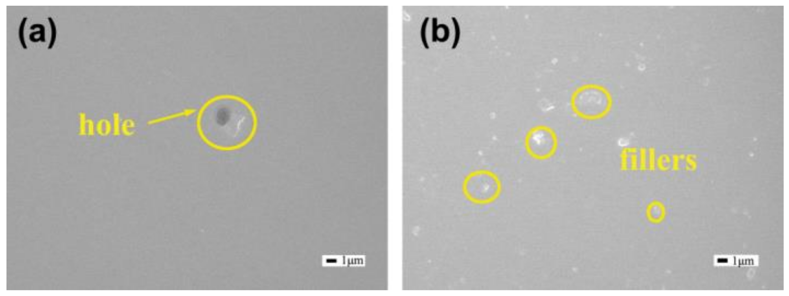
The thickness of the Blank coating is about 54 μm ± 3 μm, and the one of the coatings doped with nanofillers is approximately 59 μm ± 3 μm. Figure 6 depicts the surface morphology of Blank coating and M + V coating characterized by SEM. There are a few holes on the Blank coating (Figure 6a). Some local uplifts are found on the surface of the M + V coating (Figure 6b), but there are no holes or cracks. The added nanofillers disperse homogeneously in coating matrix and reduce the holes. SEM images of the other coatings (M + M, V + V, S + M/V, and V + M coatings) are not depicted, as they are similar with those of the M + V coating.
3.4. EIS Measurement of Coating Systems
The EIS spectra of the coated samples after immersion in 3.5 wt.% NaCl solution for 30 min and 27 days are depicted in Figure 7. The Nyquist plots after two days and 10 days are presented in Figure S1 of the Supplementary Material showing the evolution of coatings. At the beginning of immersion (Figure 7b), the |Z|0.01 Hz of all the samples exceeds 1 × 10⁹ Ω·cm2. The |Z|0.01 Hz of the V + M and M + V coatings is close to 1 × 10¹¹ Ω·cm2, and higher than that of the S + M/V coating (1.16 × 10¹⁰ Ω·cm2). The phase diagram in Figure 7c depicts only one time constant related to the coatings, showing a good barrier effect of coating systems. The electrical equivalent circuit in Figure 7c is used for the fitting process. Rs and Rcoat stand for the solution resistance and the coating resistance, respectively. The phase angles of the V + M and M + V coatings are close to 90° in a wider frequency range from 10−1 to 105 Hz. Capacitive behaviors indicate good barrier performances of the coating systems at the initial stage of immersion [29]. The coatings that were added with nanofillers provide better barrier properties, which is likely connected to the decrease of holes and the slightly increase of coating thickness [30].
The impedance spectra of samples immersed in 3.5 wt.% NaCl solution for 27 days are exhibited in Figure 7e. The impedance values of all the coatings decreased, which might be caused by the formation of defects. The coatings with two types of inhibitors (V + M and M + V coatings) exhibit higher impedance than the coatings with a single inhibitor (V + V and M + M coating), suggesting the availability of inhibitor combination in corrosion protection of coating systems. But, the S + M/V coating, with a mixture of GO/LDHs-MBT and GO/LDHs-VOx in the epoxy coating, shows smaller impedance than the coatings with a single inhibitor. The |Z|0.01 Hz of the M + V coatings, about 2.13 × 10⁷ Ω·cm2, is two times of magnitude higher than the values of the Blank coating. This result indicates the outstanding protection performance of M + V coating after long time immersion.
The electrical equivalent circuit used to fit the experimental spectra is drawn in Figure 7f. The Rs, CPEcoat, Rcoat, CPEdl, Rct, CPEw, Rw represent the solution resistance, constant phase element of the coating, coating resistance, constant phase element of double layer, charge transfer resistance, constant phase element of corrosion product layer, and corrosion product layer resistance separately. The phase diagram in Figure 7f reveals the presence of three time constants. The time constant at high-frequency relates to the coating properties (CPEcoat and Rcoat). After immersion for 27 days, the native oxide layer is destructive and cannot be detected. So, the second one at middle-frequency is associated with corrosion process at the interface of alloy and coatings (CPEdl and Rct). And the third time constant at low-frequency relates to corrosion products (CPEw and Rw) [18,31,32]. For better investigations, the calculated values of parameters are presented in Table 2. The fitting goodness for all of the coating systems was χ2 < 0.005. The resistance values of all coatings with nanofillers are higher than that of blank coating. The increase can be ascribed to the encapsulated inhibitors, which inhibit the corrosion process and increase resistances. M + M coating has a higher Rct and a lower CPEdl than V + V coating, which shows M + M coating more effectively inhibits the corrosion process than the V + V coating. The Rct and CPEdl of V + M coating are close to values of M + M coating, but V + M coating exhibits a higher Rw and a lower CPEw than M + M coating. That means the V + M coating does better in inhibiting the mass transport processes. M + V coating, different from V + M coating in the order of added inhibitors, possesses the highest Rct, Rw and lowest CPEdl, CPEw among all of the samples.
Although GO/LDHs-VOx provides better corrosion inhibition properties in solution, the corrosion protection properties of M + M coating are better than those of the V + V coating. It is well-known that the filiform corrosion on organic-coated metal surfaces exhibits acidic conditions (pH~1) in the filament head as a consequence of cation hydrolysis [21,33,34]. Therefore, inhibitors working at acidic conditions should be added closer to the metal/coating interface. That means sol-gel coating in these systems added with GO/LDHs-MBT has better protection properties than that added with GO/LDHs-VOx. The filiform corrosion proceeds cathodic oxygen reduction toward the trailing edge and it exhibits alkaline conditions. MBT is able to form a water-insoluble film in alkaline environment, but the film is easily peeled off from the surface and probably do not work on the corrosion inhibition [35]. On the contrary, vanadate species present in the alkaline environment is mainly monovanadate, which can block reactive sites by the adsorbed inhibitors on surface and remarkably reduce the rate of the oxygen reduction reaction proceeded at the trailing edge of the filiform corrosion [36]. So, GO/LDHs-VOx added in epoxy coating can further inhibit the corrosion of alloys, and the best protection property belongs to the M + V coating. It is demonstrated that combination of GO/LDHs-MBT and GO/LDHs-VOx in different coating layers (V + M and M + V) significantly improves corrosion protection performances. Furthermore, the response order of added inhibitors can enhance the corrosion protection properties.
3.5. Salt Spray Test
The optical photographs of coated samples after 840 h exposure in salt spray cabinet are displayed in Figure 8. There are large filaments and obvious corrosion pits on Blank coating (Figure 8a), suggesting poor corrosion protection of coating system without fillers. In S + M/V coating (Figure 8d), the size of corrosion pits is smaller, but a large filament is still observed. Inclusion of GO/LDHs-VOx into sol-gel coating (Figure 8b,e) causes an evident decrement in the size of corrosion pits. Nonetheless, filaments are existed in the coatings. The filiform corrosion of V + M coating is slight contrast to V + V coating. Interestingly, no filament is seen on the surface of M + M (Figure 8c) and M + V (Figure 8f) coatings with GO/LDHs-MBT added in the sol-gel coating. But, the presence of white corrosion products and numerous corrosion pits is evident on the surface of M + M coating. When combining with GO/LDHs-VOx in epoxy coating, the M+V coating presents a few tiny pits on the surface. In fact, the M + V coating possesses the best protection performance when compared to the rest of samples.
The images again visually confirm the effectiveness of the introduction of GO/LDHs-MBT and GO/LDHs-VOx into the coatings. The reason for the outstanding corrosion protection performances of the M + V coating is explained, as follows. When defects appear in the coating and aggressive species access to the interface of substrate and sol-gel coating, filiform corrosion occurs. Because the filament head exhibits an acidic condition, the addition of GO/LDHs-MBT in the sol-gel coating (nearest to metal substrates) can transfer rapidly and effectively inhibit the corrosion. Thus, the coating systems with GO/LDHs-MBT in the sol-gel coating have better protection properties (M + M vs. V + V and M + V vs. V + M). Nonetheless, because GO/LDHs-MBT cannot effectively inhibit the oxygen reduction reaction at alkaline environment, the coating system incorporated GO/LDHs-MBT both in sol-gel coating and epoxy coating does not have good corrosion protection properties (M + M vs. M + V or V + M). White corrosion products and corrosion pits are obviously observed on the sample with M+M coating. Whereas, vanadate anions released from the GO/LDHs-VOx in epoxy coating can form a protection film at alkaline environment and remarkably inhibit the oxygen reduction reaction. Thus, the coating system of the M + V coating does better in corrosion protection. It is demonstrated that the response order of inhibitors plays an important role in inhibitor combination.
3.6. Active Corrosion Protection of Coating Systems
To evaluate the active protection that was offered by the coatings with inhibitor combination and different response order, different coating systems (Blank, S + M/V, M + V and V + M) were scratched by a sharp blade and immersed in a 0.05 M NaCl solution for EIS measurement. In order to make scratched area controlled between different samples, the scratches were created under a constant force. The scratches were deep enough to ensure that the metal surface was exposed to the NaCl solution. The evolution of the Bode plots and optical photographs of the samples after immersion are depicted in Figure 9. The impedance values of Blank coating (Figure 9a) exhibit a continuous decrease with time. In contrast, the impedance values of the coatings added with inhibitors (Figure 9b–d) shows a slower decrease. It keeps almost constant in V + M coating. After 13 days immersion, the values of impedance at low frequency (|Z|0.01 Hz) of Blank, S + M/V, M + V, and V + M coatings decrease to 2.07 × 10⁴ Ω·cm2, 5.15 × 10⁴ Ω·cm2, 8.32 × 10⁴ Ω·cm2, and 8.89 × 10⁴ Ω·cm2, respectively. The impedance value of S + M/V coating is at least 2 times higher than that of Blank coating. The values of V + M and M + V coatings are at 4 times higher than that of Blank coating. Therefore, the addition of corrosion inhibitors provides active protection of coatings. For the combination of corrosion inhibitors, a much better protection performance is achieved by adding nanofillers into the layer closer to the metal surface. Inhibitors are released and worked on the corrosive areas once corrosion occurred. Additionally, there is no obvious distinction between the impedance values of V + M or M + V coatings. The reason is that oxygen concentration has no change in the anode and cathode areas as the scratches thoroughly contact with electrolyte, and the corrosive activity does not belong to filiform corrosion. The response order of MBT anions and vanadate anions is not a key factor to inhibition any more.
Furthermore, the optical photographs of the scratched coatings after immersion for 13 days are agreed with the EIS measurements. In Blank coating, numerous corrosion products are found inside and around the scratch. The amount of corrosion products decreases in the S + M/V coating. Corrosion products are hardly observed in the scratch of V + M and M + V coatings.
3.7. Corrosion Protection Mechanism of the M + V Coating System
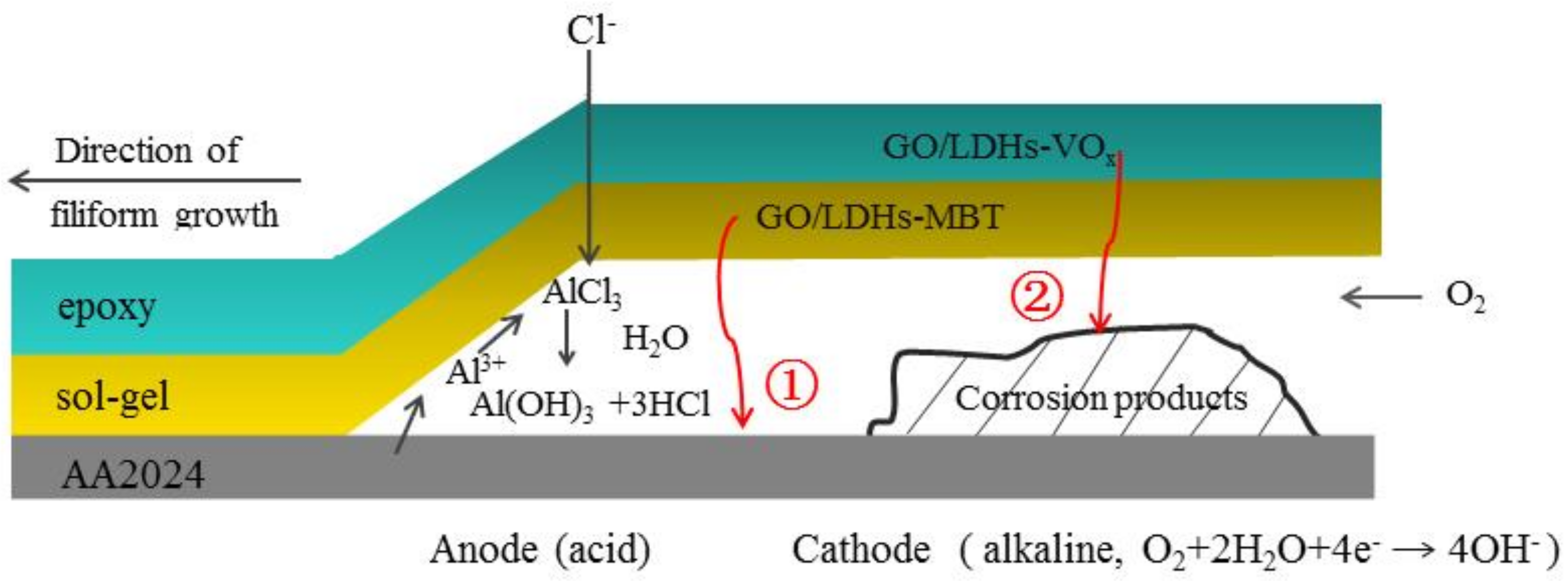
According to the above experimental results and analysis, a schematic diagram of the M + V coating is displayed in Figure 10. Firstly, the homogeneously dispersion of nanofillers, the reduction of holes in coating, and the good barrier properties improve the passive protection of the coating [17]. When defects produced in the coating and corrosive species have access to the interface of substrate and sol-gel coating, filiform corrosion occurred. Filament heads fill with electrolyte and aggressive anions (such as Cl−), and typically exhibit a low pH (as low as pH ≈ 1) resulting from cation hydrolysis. The trailing edge is proceeding cathodic oxygen reduction reaction and having alkaline environment [33]. MBT anions released from GO/LDHs-MBT, which is embedded in the sol-gel coating, are the closest to substrates and transport fast to corrosive area. Then, they adsorb on both aluminum oxide and aluminum surface, especially on the copper rich areas, and form a protective film in anodic areas at a very short time [12,35,37]. Subsequently, vanadate anions that are released from GO/LDHs-VOx in the outer and thicker epoxy coating adsorb on the surface and form a film, which remarkably inhibits the oxygen reduction reaction [36,38]. Furthermore, due to GO/LDHs-VOx are greater in numbers than GO/LDHs-MBT, vanadate anions can offer a long-term protection when MBT anions are no longer available. Above all, because MBT anions depress the corrosion in anodic areas and vanadate anions inhibit the cathodic oxygen reduction reaction with inhibitor response order, the M + V coating system combining GO/LDHs-MBT in sol-gel coating and GO/LDHs-VOx in epoxy coating shows good corrosion protection properties to aluminum alloys.
4. Conclusions
The combination of GO/LDHs-MBT and GO/LDHs-VOx showed a constructive effect on the inhibition properties for AA2024 in NaCl solution. The coating systems with GO/LDHs-MBT or GO/LDHs-VOx, in contrast to Blank coating, have enhanced corrosion protection for substrates. It is ascribed to the improved passive protection and the active corrosion protection derived from loaded inhibitors. Moreover, the best protection performance was found for the M + V coating consisting of sol-gel coating with GO/LDHs-MBT and epoxy coating with GO/LDHs-VOx, since the coating system had a proper response order with inhibitor combination. When filiform corrosion occurs, MBT anions from the nearest coating transfer to corrosive region immediately, and then form a protective film by adsorption. Following, vanadate anions from the out and thick epoxy coating inhibit the cathodic oxygen reduction reaction. Above all, considering the inhibitor response order, when combining inhibitors, is a promising way to enhance the corrosion protection performances of coating system.
Supplementary Materials
The following are available online at https://www.mdpi.com/2079-6412/8/10/365/s1, Figure S1: Nyquist plots of AA2024 coated with different coatings immersed in 3.5 wt.% NaCl solution for (a) 2 and (b) 10 days.
Author Contributions
Conceptualization, M.Y. and X.Z.; Formal Analysis, M.Y., X.Z. and X.K.; Investigation, X.Z. and L.X.; Methodology, X.Z., L.X. and B.X.; Supervision, M.Y.; Writing—Original Draft, X.Z. and L.X.; Writing—Review & Editing, M.Y., J.L. and S.L.
Funding
This research was funded by the Beijing Nova Program (No. Z161100004916061).
Acknowledgments
Authors would like to acknowledge Qing Yu and Yang Nan for their technical assistance.
Conflicts of Interest
The authors declare no conflict of interest.
References
- Sathiyanarayanan, S.; Azim, S.S.; Venkatachari, G. A new corrosion protection coating with polyaniline–TiO2 composite for steel. Electrochim. Acta 2007, 52, 2068–2074. [Google Scholar] [CrossRef]
- García, S.J.; Fischer, H.R.; van der Zwaag, S. A critical appraisal of the potential of self healing polymeric coatings. Prog. Org. Coat. 2011, 72, 211–221. [Google Scholar] [CrossRef]
- Snihirova, D.; Lamaka, S.V.; Cardoso, M.M.; Condeço, J.A.D.; Ferreira, H.E.C.S.; de Fatima Montemor, M. pH-sensitive polymeric particles with increased inhibitor-loading capacity as smart additives for corrosion protective coatings for AA2024. Electrochim. Acta 2014, 145, 123–131. [Google Scholar] [CrossRef]
- Plawecka, M.; Snihirova, D.; Martins, B.; Szczepanowicz, K.; Warszynski, P.; Montemor, M.F. Self healing ability of inhibitor-containing nanocapsules loaded in epoxy coatings applied on aluminium 5083 and galvanneal substrates. Electrochim. Acta 2014, 140, 282–293. [Google Scholar] [CrossRef]
- Markley, T.A.; Forsyth, M.; Hughes, A.E. Corrosion Protection of AA2024-T3 using rare earth diphenyl phosphates. Electrochim. Acta 2007, 52, 4024–4031. [Google Scholar] [CrossRef]
- Montemor, M.F.; Snihirova, D.V.; Taryba, M.G.; Lamaka, S.V.; Kartsonakis, I.A.; Balaskas, A.C.; Kordas, G.; Tedim, J.; Kuznetsova, A.; Zheludkevich, M.L.; et al. Evaluation of self-healing ability in protective coatings modified with combinations of layered double hydroxides and cerium molibdate nanocontainers filled with corrosion inhibitors. Electrochim. Acta 2012, 60, 31–40. [Google Scholar] [CrossRef]
- Kallip, S.; Bastos, A.C.; Yasakau, K.A.; Zheludkevich, M.L.; Ferreira, M.G.S. Synergistic corrosion inhibition on galvanically coupled metallic materials. Electrochem. Commun. 2012, 20, 101–104. [Google Scholar] [CrossRef]
- Zhao, J.; Chen, G. The synergistic inhibition effect of oleic-based imidazoline and sodium benzoate on mild steel corrosion in a CO2-saturated brine solution. Electrochim. Acta 2012, 69, 247–255. [Google Scholar] [CrossRef]
- Garcia, S.J.; Markley, T.A.; Mol, J.M.C.; Hughes, A.E. Unravelling the corrosion inhibition mechanisms of bi-functional inhibitors by EIS and SEM-EDS. Corros. Sci. 2013, 69, 346–358. [Google Scholar] [CrossRef]
- Liu, J.; Wang, D.; Gao, L.; Zhang, D. Synergism between cerium nitrate and sodium dodecylbenzenesulfonate on corrosion of AA5052 aluminium alloy in 3 wt.% NaCl solution. Appl. Surf. Sci. 2016, 389, 369–377. [Google Scholar] [CrossRef]
- Snihirova, D.; Lamaka, S.V.; Taheri, P.; Mol, J.M.C.; Montemor, M.F. Comparison of the synergistic effects of inhibitor mixtures tailored for enhanced corrosion protection of bare and coated AA2024-T3. Surf. Coat. Technol. 2016, 303, 342–351. [Google Scholar] [CrossRef]
- Abdolah Zadeh, M.; Tedim, J.; Zheludkevich, M.; van der Zwaag, S.; Garcia, S.J. Synergetic active corrosion protection of AA2024-T3 by 2D-anionic and 3D-cationic nanocontainers loaded with Ce and mercaptobenzothiazole. Corros. Sci. 2018, 135, 35–45. [Google Scholar] [CrossRef]
- Saei, E.; Ramezanzadeh, B.; Amini, R.; Kalajahi, M.S. Effects of combined organic and inorganic corrosion inhibitors on the nanostructure cerium based conversion coating performance on AZ31 magnesium alloy: Morphological and corrosion studies. Corros. Sci. 2017, 127, 186–200. [Google Scholar] [CrossRef]
- Kowalczyk, K.; Kugler, S.; Spychaj, T. Antistatic polyurethane coats with hybrid carbon nanofillers. Polimery 2014, 59, 650–655. [Google Scholar] [CrossRef]
- Okafor, P.A.; Singh-Beemat, J.; Iroh, J.O. Thermomechanical and corrosion inhibition properties of graphene/epoxy ester–siloxane–urea hybrid polymer nanocomposites. Prog. Org. Coat. 2015, 88, 237–244. [Google Scholar] [CrossRef]
- Jena, K.K.; Narayan, R.; Alhassan, S.M. Highly branched graphene siloxane−polyurethane-urea (Pu-urea) hybrid coatings. Prog. Org. Coat. 2017, 111, 343–353. [Google Scholar] [CrossRef]
- Xue, B.; Yu, M.; Liu, J.; Li, S.; Xiong, L.; Kong, X. Synthesis of inhibitor nanocontainers with two-dimensional structure and their anticorrosion action in sol-gel coating on Aa2024-T3 aluminum alloy. J. Electrochem. Soc. 2017, 164, C641–C652. [Google Scholar] [CrossRef]
- Zheludkevich, M.L.; Serra, R.; Montemor, M.F.; Yasakau, K.A.; Salvado, I.M.M.; Ferreira, M.G.S. Nanostructured sol-gel coatings doped with cerium nitrate as pre-treatments for AA2024-T3: Corrosion protection performance. Electrochim. Acta 2005, 51, 208–217. [Google Scholar] [CrossRef]
- ASTM B117–18 Standard Practice for Operating Salt Spray (Fog) Apparatus; ASTM International: West Conshohocken, PA, USA, 2018.
- Luo, X.H.; Yuan, S.; Pan, X.Y.; Zhang, C.X.; Du, S.; Liu, Y.L. Synthesis and enhanced corrosion protection performance of reduced graphene oxide nanosheet/ZnAl layered double hydroxide composite films by hydrothermal continuous flow method. ACS Appl. Mater. Interfaces 2017, 9, 18263–18275. [Google Scholar] [CrossRef] [PubMed]
- Tedim, J.; Poznyak, S.K.; Kuznetsova, A.; Raps, D.; Hack, T.; Zheludkevich, M.L.; Ferreira, M.G. Enhancement of active corrosion protection via combination of inhibitor-loaded nanocontainers. ACS Appl. Mater. Interfaces 2010, 2, 1528–1535. [Google Scholar] [CrossRef] [PubMed]
- Li, H.; Zhu, G.; Liu, Z.-H.; Yang, Z.; Wang, Z. Fabrication of a hybrid graphene/layered double hydroxide material. Carbon 2010, 48, 4391–4396. [Google Scholar] [CrossRef]
- Fang, J.; Li, M.; Li, Q.; Zhang, W.; Shou, Q.; Liu, F.; Zhang, X.; Cheng, J. Microwave-assisted synthesis of coal-layered double hydroxide/graphene oxide composite and its application in supercapacitors. Electrochim. Acta 2012, 85, 248–255. [Google Scholar] [CrossRef]
- Beattie, D.A.; Kempson, I.M.; Fan, L.-J.; Skinner, W.M. Synchrotron XPS studies of collector adsorption and co-adsorption on gold and gold: Silver alloy surfaces. Int. J. Miner. Process. 2009, 92, 162–168. [Google Scholar] [CrossRef]
- Kazansky, L.P.; Selyaninov, I.A.; Kuznetsov, Y.I. Adsorption of 2-mercaptobenzothiazole on copper surface from phosphate solutions. Appl. Surf. Sci. 2012, 258, 6807–6813. [Google Scholar] [CrossRef]
- Wang, Z.; Li, Q.; Lin, Z.; Whiddon, R.; Qiu, K.; Kuang, M.; Cen, K. Transformation of nitrogen and sulphur impurities during hydrothermal upgrading of low quality coals. Fuel 2016, 164, 254–261. [Google Scholar] [CrossRef]
- Motola, M.; Satrapinskyy, L.; Čaplovicová, M.; Roch, T.; Gregor, M.; Grančič, B.; Greguš, J.; Čaplovič, L’.; Plesch, G. Enhanced photocatalytic activity of hydrogenated and vanadium doped TiO2 nanotube arrays grown by anodization of sputtered Ti layers. Appl. Surf. Sci. 2018, 434, 1257–1265. [Google Scholar] [CrossRef]
- Luo, H.; Dong, C.F.; Xiao, K.; Li, X.G. Characterization of passive film on 2205 duplex stainless steel in sodium thiosulphate solution. Appl. Surf. Sci. 2011, 258, 631–639. [Google Scholar] [CrossRef]
- Liu, J.; Yu, Q.; Yu, M.; Li, S.; Zhao, K.; Xue, B.; Zu, H. Silane modification of titanium dioxide-decorated graphene oxide nanocomposite for enhancing anticorrosion performance of epoxy coatings on AA-2024. J. Alloys Compd. 2018, 744, 728–739. [Google Scholar] [CrossRef]
- Ramezanzadeh, B.; Ahmadi, A.; Mahdavian, M. Enhancement of the corrosion protection performance and cathodic delamination resistance of epoxy coating through treatment of steel substrate by a novel nanometric sol-gel based silane composite film filled with functionalized graphene oxide nanosheets. Corros. Sci. 2016, 109, 182–205. [Google Scholar] [CrossRef]
- Borisova, D.; Mohwald, H.; Shchukin, D.G. Influence of embedded nanocontainers on the efficiency of active anticorrosive coatings for aluminum alloys part I: Influence of nanocontainer position. ACS Appl. Mater. Interfaces 2013, 5, 80–87. [Google Scholar] [CrossRef] [PubMed]
- Maia, F.; Tedim, J.; Lisenkov, A.D.; Salak, A.N.; Zheludkevich, M.L.; Ferreira, M.G. Silica nanocontainers for active corrosion protection. Nanoscale 2012, 4, 1287–1298. [Google Scholar] [CrossRef] [PubMed]
- McMurray, H.N.; Williams, G.; O’Driscoll, S. Chromate inhibition of filiform corrosion on organic coated AA2024-T3 studied using the scanning kelvin probe. J. Electrochem. Soc. 2004, 151, B406–B414. [Google Scholar] [CrossRef]
- Williams, G.; McMurray, H.N. Polyaniline inhibition of filiform corrosion on organic coated AA2024-T3. Electrochim. Acta 2009, 54, 4245–4252. [Google Scholar] [CrossRef]
- Ohsawa, M.; Suetaka, W. Spectro-electrochemical studied of the corrosion inhibition of copper by mercaptobenzothiazole. Corros. Sci. 1979, 19, 709–722. [Google Scholar] [CrossRef]
- Iannuzzi, M.; Frankel, G.S. Mechanisms of corrosion inhibition of AA2024-T3 by vanadates. Corros. Sci. 2007, 49, 2371–2391. [Google Scholar] [CrossRef] [Green Version]
- Khramov, A.N.; Voevodin, N.N.; Balbyshev, V.N.; Mantz, R.A. Sol–gel-derived corrosion-protective coatings with controllable release of incorporated organic corrosion inhibitors. Thin Solid Films 2005, 483, 191–196. [Google Scholar] [CrossRef]
- Ralston, K.D.; Young, T.L.; Buchheit, R.G. electrochemical evaluation of constituent intermetallics in aluminum alloy 2024-T3 exposed to aqueous vanadate inhibitors. J. Electrochem. Soc. 2009, 156, C135–C146. [Google Scholar] [CrossRef]
Figure 1.
Schematic diagram of coating system added with different combinations of the GO/LDHs-MBT and GO/LDHs-VOx in sol-gel and epoxy coating.
Figure 1.
Schematic diagram of coating system added with different combinations of the GO/LDHs-MBT and GO/LDHs-VOx in sol-gel and epoxy coating.

Figure 2.
(a) X-ray diffraction (XRD) spectra and (b) Fourier transform infrared spectrometer (FTIR) spectra of GO/LDHs, GO/LDHs-MBT, and GO/LDHs-VOx.
Figure 2.
(a) X-ray diffraction (XRD) spectra and (b) Fourier transform infrared spectrometer (FTIR) spectra of GO/LDHs, GO/LDHs-MBT, and GO/LDHs-VOx.
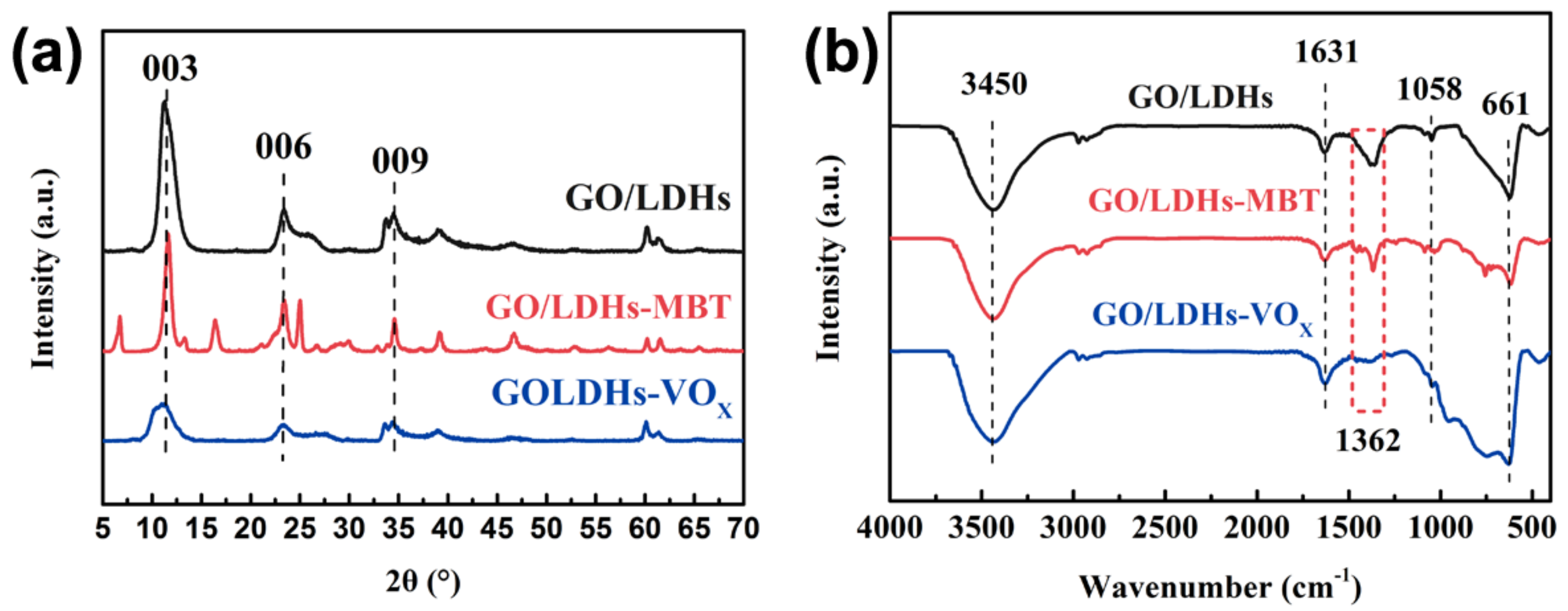
Figure 3.
Scanning electron microscopy (SEM) and transmission electron microscopy (TEM) images of (a,d) nanocontainer GO/LDHs, (b,e) loaded with inhibitors MBT (GO/LDHs-MBT), and (c,f) loaded with inhibitors vanadate (GO/LDHs-VOx).
Figure 3.
Scanning electron microscopy (SEM) and transmission electron microscopy (TEM) images of (a,d) nanocontainer GO/LDHs, (b,e) loaded with inhibitors MBT (GO/LDHs-MBT), and (c,f) loaded with inhibitors vanadate (GO/LDHs-VOx).

Figure 4.
(a) X-ray photoelectron spectroscopy (XPS) spectra of GO, GO/LDHs, GO/LDHs-MBT, and GO/LDHs-VOx; (b) C 1s XPS spectrum of GO and (c) GO/LDHs; (d) S 2p XPS spectrum of GO/LDHs-MBT; and (e) V 2p XPS spectrum of GO/LDHs-VOx.
Figure 4.
(a) X-ray photoelectron spectroscopy (XPS) spectra of GO, GO/LDHs, GO/LDHs-MBT, and GO/LDHs-VOx; (b) C 1s XPS spectrum of GO and (c) GO/LDHs; (d) S 2p XPS spectrum of GO/LDHs-MBT; and (e) V 2p XPS spectrum of GO/LDHs-VOx.

Figure 5.
(a) Electrochemical impedance spectroscopy (EIS) spectra of bare AA2024 after immersion for two days in 0.05 M NaCl with and without nanofillers; (b) equivalent electrical circuits used for fitting in 0.05 M NaCl and (c) 0.05 M NaCl with nanofillers; and (d) optical photos of the AA2024 surface after immersion for 10 days in 0.05 M NaCl doped with different nanofillers.
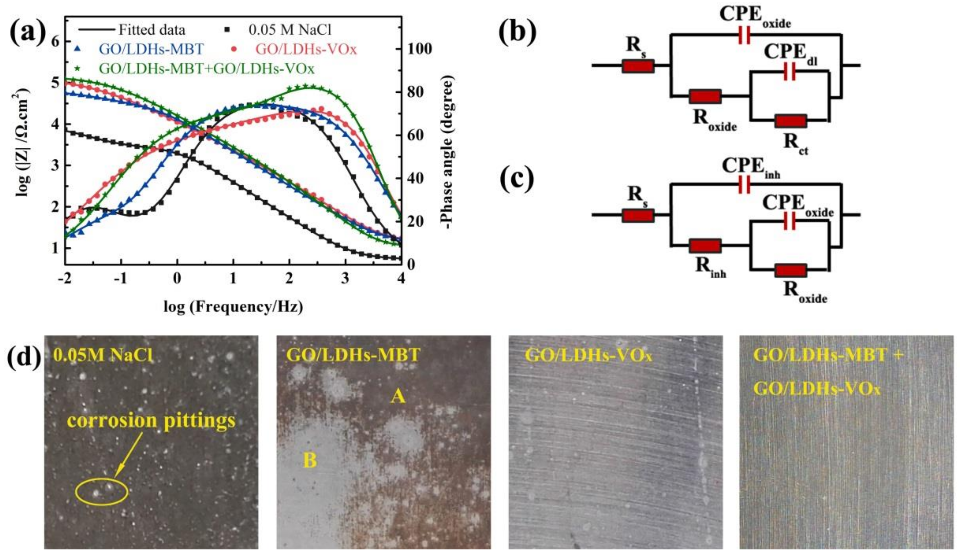
Figure 6.
Scanning electron microscopy (SEM) images of surface morphology of (a) Blank coating and (b) M + V coating.
Figure 6.
Scanning electron microscopy (SEM) images of surface morphology of (a) Blank coating and (b) M + V coating.

Figure 7.
Electrochemical impedance spectroscopy (EIS) spectra and the equivalent electrical circuits of AA2024 coated with different coatings immersed in 3.5 wt.% NaCl solution for (a–c) 30 min and (d–f) 27 days.
Figure 7.
Electrochemical impedance spectroscopy (EIS) spectra and the equivalent electrical circuits of AA2024 coated with different coatings immersed in 3.5 wt.% NaCl solution for (a–c) 30 min and (d–f) 27 days.

Figure 8.
Optical photographs of AA2024 coated with (a) Blank coating, (b) V + V coating, (c) M + M coating, (d) S + M/V coating, (e) V + M coating, and (f) M + V coating after 840 h of exposure to salt spray test.
Figure 8.
Optical photographs of AA2024 coated with (a) Blank coating, (b) V + V coating, (c) M + M coating, (d) S + M/V coating, (e) V + M coating, and (f) M + V coating after 840 h of exposure to salt spray test.

Figure 9.
The evolution of Bode plots and optical photographs of scratched coatings immersed in a 0.05 M NaCl solution for 13 days: (a) Blank coating, (b) S + M/V coating, (c) V + M coating, and (d) M + V coating.
Figure 9.
The evolution of Bode plots and optical photographs of scratched coatings immersed in a 0.05 M NaCl solution for 13 days: (a) Blank coating, (b) S + M/V coating, (c) V + M coating, and (d) M + V coating.

Figure 10.
Schematic diagram of protective mechanism of the M + V coating: MBT anions inhibited the corrosion in anodic areas immediately, and vanadate anions reduced the kinetics of the cathodic oxygen reduction reaction.
Figure 10.
Schematic diagram of protective mechanism of the M + V coating: MBT anions inhibited the corrosion in anodic areas immediately, and vanadate anions reduced the kinetics of the cathodic oxygen reduction reaction.


Table 1.
Summary of the tested coating systems with various combinations of graphene oxide/layered double hydroxides-2-mercaptobenzothiazole (GO/LDHs-MBT) and graphene oxide/layered double hydroxides-vanadate (GO/LDHs-VOx).
Table 1.
Summary of the tested coating systems with various combinations of graphene oxide/layered double hydroxides-2-mercaptobenzothiazole (GO/LDHs-MBT) and graphene oxide/layered double hydroxides-vanadate (GO/LDHs-VOx).
| Coating Label | Description | |
|---|---|---|
| Sol-Gel Layer with Inhibitors | Epoxy Coating with Inhibitors | |
| Blank | – | – |
| M + M | GO/LDHs-MBT | GO/LDHs-MBT |
| V + V | GO/LDHs-VOx | GO/LDHs-VOx |
| S + M/V | – | GO/LDHs-MBT + GO/LDHs-VOx |
| V + M | GO/LDHs-VOx | GO/LDHs-MBT |
| M + V | GO/LDHs-MBT | GO/LDHs-VOx |
Table 2.
Resistance and capacitance parameters of different coatings after immersed in 3.5 wt.% NaCl solution for 27 days.
Table 2.
Resistance and capacitance parameters of different coatings after immersed in 3.5 wt.% NaCl solution for 27 days.
| Coating System | Rs (Ω·cm2) | Rcoat (Ω·cm2) | CPEcoat | Rct (Ω·cm2) | CPEdl | Rw (Ω·cm2) | CPEw | |||
|---|---|---|---|---|---|---|---|---|---|---|
| Ycoat | n | Ydl | n | Yw | n | |||||
| Blank | 6.42 | 2.46 × 10³ | 3.42 × 10⁻⁹ | 0.974 | 4.99 × 10⁴ | 7.41 × 10⁻⁶ | 0.647 | 1.01 × 10⁵ | 7.98 × 10⁻⁵ | 0.595 |
| S + M/V | 5.37 | 3.43 × 10⁴ | 4.56 × 10⁻⁹ | 0.821 | 2.73 × 10⁵ | 1.62 × 10⁻⁷ | 0.846 | 1.27 × 10⁵ | 2.56 × 10⁻⁵ | 0.918 |
| V + V | 2.56 | 5.14 × 10⁴ | 1.21 × 10⁻⁹ | 0.815 | 4.76 × 10⁵ | 1.84 × 10⁻⁷ | 0.818 | 6.27 × 10⁶ | 1.01 × 10⁻⁵ | 0.572 |
| M + M | 2.63 | 5.71 × 10⁴ | 1.93 × 10⁻⁹ | 0.785 | 3.30 × 10⁶ | 6.84 × 10⁻⁸ | 0.759 | 4.95 × 10⁶ | 2.00 × 10⁻⁶ | 0.717 |
| V + M | 1.87 | 5.92 × 10⁴ | 4.18 × 10⁻¹⁰ | 0.887 | 2.84 × 10⁶ | 8.31 × 10⁻⁸ | 0.712 | 8.63 × 10⁶ | 3.67 × 10⁻⁷ | 0.796 |
| M + V | 2.07 | 6.04 × 10⁴ | 3.50 × 10⁻¹⁰ | 0.914 | 5.95 × 10⁶ | 2.68 × 10⁻⁸ | 0.845 | 2.13 × 10⁷ | 1.76 × 10⁻⁷ | 0.934 |
© 2018 by the authors. Licensee MDPI, Basel, Switzerland. This article is an open access article distributed under the terms and conditions of the Creative Commons Attribution (CC BY) license (http://creativecommons.org/licenses/by/4.0/).
Share and Cite
MDPI and ACS Style
Yu, M.; Zhao, X.; Xiong, L.; Xue, B.; Kong, X.; Liu, J.; Li, S. Improvement of Corrosion Protection of Coating System via Inhibitor Response Order. Coatings 2018, 8, 365. https://doi.org/10.3390/coatings8100365
AMA Style
Yu M, Zhao X, Xiong L, Xue B, Kong X, Liu J, Li S. Improvement of Corrosion Protection of Coating System via Inhibitor Response Order. Coatings. 2018; 8(10):365. https://doi.org/10.3390/coatings8100365
Chicago/Turabian StyleYu, Mei, Xiangni Zhao, Liangliang Xiong, Bing Xue, Xiangxin Kong, Jianhua Liu, and Songmei Li. 2018. "Improvement of Corrosion Protection of Coating System via Inhibitor Response Order" Coatings 8, no. 10: 365. https://doi.org/10.3390/coatings8100365
Note that from the first issue of 2016, this journal uses article numbers instead of page numbers. See further details here.