Curve-Correction Factor for Characterization of the Output of a Three-Dimensional Curved Photovoltaic Module on a Car Roof


1
Organization for Promotion of Tenure Track, University of Miyazaki, Miyazaki 889-2192, Japan
2
X-Frontier Division, Toyota Motor Corporation, Susono, Shizuoka 410-1193, Japan
3
Senior Research Scholar Yamaguchi Laboratory, Toyota Technological Institute, Nagoya 468-8511, Japan
*
Author to whom correspondence should be addressed.
Coatings 2018, 8(12), 432; https://doi.org/10.3390/coatings8120432
Submission received: 30 August 2018
/
Revised: 20 November 2018
/
Accepted: 26 November 2018
/
Published: 27 November 2018
(This article belongs to the Special Issue Thin Film Solar Cells: Fabrication, Characterization and Applications)
Abstract
:For modeling the energy generation of three-dimensional car roof photovoltaic (PV) panels, it is essential to define a scientifically accurate method to model the amount of solar irradiance received by the panel. Additionally, the average annual irradiance incident on car roofs must be evaluated, because the PV module is often shaded during driving and when parked. The curve-correction factor, which is a unique value depending on the three-dimensional curved shape of the PV module, is defined in this paper. The curve-correction factor was calculated using a ray-trace simulator. It was found that the shape of the curved surface affected the curve-correction factor. The ratio of the projection area to the curved surface area of most car roofs is 0.85–0.95, and the annual curve-correction factor lies between 0.70 and 0.90. The annual irradiance incident on car roofs was evaluated using a mobile multipyranometer array system for one year (September 2017–August 2018). It is estimated that the effective annual solar radiation for curved PV modules is 2.53–3.52 kWh m−2/day.
1. Introduction
Electric vehicles (EVs) and plug-in hybrid vehicles (PHVs) significantly cut carbon emissions compared to petrol or diesel cars. Solar energy is one of the most direct and efficient candidates for supplying renewable energy to these vehicles [1,2,3,4,5]. Saitoh et al. [6] concluded that the photovoltaic (PV) cell and flywheel made it possible for such vehicles to become self-sufficient in terms of energy requirements. With the advancement of car technology, it is expected that 2/3 of personally owned vehicles will be able to run on solar energy absorbed on the roof. Moreover, it is estimated that this will cut 8% of all greenhouse gas emissions [7].
Unlike PV panels on building roofs or ground installations, car roof PV panels have three-dimensional curved surfaces. An example is the Solar Prius PHV from Toyota, which was released in 2016 [8]. For fabricating curved PV panels, thin-film solar cell technologies are applied, and it has been reported that some of the highest conversion efficiency values are 21.0% for CdTe solar cells [9], 22.9% for Cu(In,Ga)Se2(CIGS) solar cells [8], and 20.1% for perovskite solar cells [10]. Additionally, CIGS solar cells on flexible substrates have achieved a conversion efficiency of 20.4% using polyimide (PI) substrates [11] and 18.0% using stainless steel (SUS) substrates [12]. However, for EVs, the module requires an efficiency of more than 30%, because of the space limitation of the car body area [7]. The InGaP/GaAs/InGaAs inverted triple-junction solar cell achieves a conversion efficiency of submodule size that reaches more than 30% under outdoor conditions [13,14,15]. Moreover, the thin and flexible InGaP/GaAs/InGaAs inverted triple-junction solar cell array structure, which is called the space solar sheet (SSS) (as space is used), was developed based on these technologies [16]. Based on a multiplication of the number of annual sales of personal cars, the expected new market of the high-performance solar cells, including multi-junction cells with an efficiency of more than 30%, is estimated to be 50 GW/year.
Drivers of cars with car-roof PV panels are interested in reducing the number and duration of battery recharges. In contrast, consumers do not consider efficiency and the management of solar energy as important. They will be satisfied if the PV charges the battery while parked. However, when one-kW PV panels are installed on a car roof, and solar energy alone fuels the car, the efficiency rating and energy prediction model are critical for running on solar energy.
To model the energy generation of three-dimensional car roof PV panels, it is essential to define a scientifically accurate method to model the amount of solar irradiance received by the panel. Since the PV module is three-dimensionally curved, some fraction of the surface will not be receiving direct solar radiation for much of the day, and therefore, the panel efficiency is much reduced. For characterization of the solar irradiance received by the panel, irradiance measurement based on a two-dimensional aperture area, such as the sloped surface, the horizontal surface, and the vertical surface, is not sufficient. Expanding measurements and modeling to a three-dimensional model is necessary. Furthermore, it is critical to recognize that the solar irradiation receipt of the roof and body will be different from that of conventional PV modules, which are generally installed on rooftops or vertical walls, free of shading, and angled to optimize the interception of solar radiation [17,18]. However, the panels on a horizontal car roof and vertical car body are not of fixed orientation, and will often be shaded during driving and whilst parked. Finally, the relative orientation of the PV modules on the car roof to the sun’s position frequently changes during driving.
In this paper, we propose a new and straightforward approach to the characterization of the three-dimensionally curved PV module illuminated by solar irradiance. We used a conversion factor that takes the influence of the three-dimensional effects into account, and converted common two-dimensional calculations of the PV panel into a three-dimensional model. Moreover, we evaluated annual irradiance incident on the car using a mobile multipyranometer array (MMPA) system.
2. Evaluation of Annual Irradiance
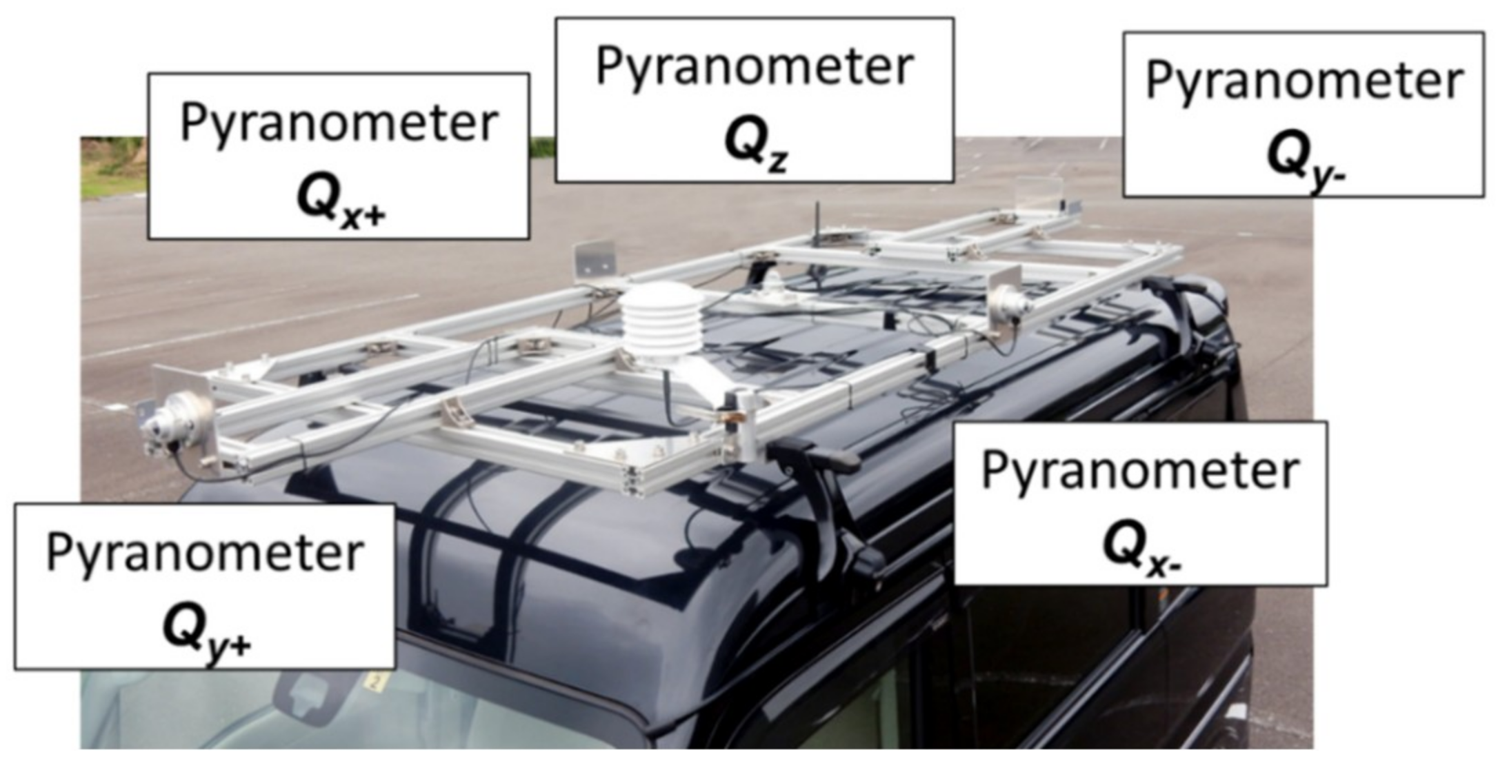
Figure 1 shows the mobile multipyranometer array (MMPA) system. The detailed MMPA system is described in [19]. The MMPA consists of five pyranometers (SR03, Hukseflux Thermal Sensors B.V., Delft, The Netherland) mounted on the car roof. Table 1 shows the specifications of the pyranometers. The pyranometer axes Qx+, Qx−, Qy+, Qy−, and Qz are defined as shown in Figure 1. One pyranometer is placed horizontally on the car roof (Qz), and four pyranometers are placed vertically facing each side of the car (Qx+, Qx−, Qy+, and Qy−). The global irradiance absorbed onto the car roof (Irrroof) is measured using a pyranometer Qz. The global irradiance absorbed onto the side of the car (Irrx+, Irrx−, Irry+, and Irry−) are measured using pyranometers Qx+, Qx−, Qy+, and Qy−. The GPS system is incorporated into the data logger, and data are recorded at one-second intervals. The measurement period was from September 2017 to August 2018. For comparison, a horizontal pyranometer (MS-602, EKO, Tokyo, Japan) was installed at the University of Miyazaki, Japan (31°49′ N, 131°24′ E).
3. Optical Simulation Procedure
3.1. Introduction of the Curve-Correction Factor
There are several possible approaches to the three-dimensional curved module that are also applicable to the current two-dimensional modeling. The most accurate and direct approach may be ray-trace modeling of the three-dimensional curved-surface object. The power output (or efficiency) and the angular characteristics of each surface element are repeatedly measured. Depending on the acceptable level of approximation, measurements of individual surface elements, and possibly the different aperture masks, will need to be repeated thousands of times, which is not practical. However, the measurement step may be simplified using an interpolation calculation given the position and angle of the normal vector of each surface element. Then, the behavior of the curved surface of the car roof PV module can be calculated by the ray-trace simulation using three-dimensional light-source modeling and importing the geometrical information from the computer-aided design (CAD) files of the car roof PV module. It is important to note that the light source function of the ray-trace simulator Zemax (Version 13, Zemax, LLC, Kirkland, WA, USA) is a kind of Monte Carlo simulation method, using random numbers and throwing dice. Inherently, the calculation results of the Monte Carlo simulations are not always repeatable. For the calculation of the efficiency, the unit area may be approximated by the integration of the triangle area from the CAD file.
However, the above approach is not realistic. For harmonizing the conventional two-dimensional panel, a curve-correction factor defined by Equation (1) will be useful:
where P is the output power of the curved PV module, Acurved surface is the curved surface area of the panel (not the projected area), Irrroof is the irradiance absorbed onto the car roof (not the global horizontal irradiance), fcurve is the curve-correction factor, and η is the module efficiency. The curve-correction factor fcurve is a unique value depending on the three-dimensional curved shape of the car roof PV module.
3.2. The Optical Model
We used the ray-trace simulator Zemax for the calculation of the curve-correction factor. For the optical simulation, the annual irradiance density (AID) model on a horizontal plane [7], as shown in Figure 2, was applied at a light source function in the optical model. The AID model was defined by the standard dataset [21], METPV11, from 47 capitals of the prefecture in Japan. The rays were distributed by the direction weighted by the AID model on the horizontal plane, as per the Monte Carlo method.
Figure 3 shows a schematic illustration of the curved surface in this model. The figure also shows the projected area, which is shown in blue. The curved surface simulated the shape of the car roof (or the three-dimensionally curved PV module). Random numbers gave parameters of the curves. The rays, which were applied in the AID model, came from the upper side. The projected area (Aprojected) was 1.82 m2, and the curved surface area (Acurved surface) was varied. The following equation defines the curve-correction factor (fcurve):
where Abscurved surface is the flux absorbed onto Acurved surface, and Absprojected is the flux absorbed onto Aprojected. Acurved surface is 1.91 m2, and the ratio of Abscurve to Absprojected is 0.917. Thus, fcurve is equal to 0.874.
4. Results
4.1. Annual Irradiance
Figure 4 shows (a) an example of measurements of global irradiances Irrx+, Irrx−, Irry+, Irry−, and Irrroof measured by the MMPA system; and (b) the driving route from the University of Miyazaki to the Miyazaki station. Measurements took place on 28 July 2018, and the weather was sunny. In this case, the car with the MMPA system traveled from the University of Miyazaki to the Miyazaki station, which is a linear distance of approximately 10 km (Figure 4b). The MMPA system measured irradiances under driving conditions and also under parking conditions [19]. Overall, the annual irradiance on the car roof could be evaluated using the MMPA system. Table 2 shows the average daily irradiances incident on the car’s roof (Irrroof), its side (Irrx+ + Irrx−), and its front and rear (Irry+ + Irry−) measured by the MMPA system between September 2017 and August 2018. The average daily irradiance of a horizontal surface is also shown for comparison. The total number of hours of sun radiation (more than 10 W m−2 in Irrroof) that was received over the year was 3374 h, while the number of hours that the car was running was approximately 6% of this. The car that had the MMPA system was parked in the parking lot of the University of Miyazaki for most of the year. The average daily irradiance of the car roof was less than that received by a horizontal surface. One of the reasons for this decrease is the shading of the MMPA system during driving and whilst parked. The car was often shaded by buildings while running, as shown by the red arrow in Figure 4a. The annual irradiance on the car roof and car body depend on the location and weather. Therefore, it is necessary to constantly measure the global irradiance receipt of the car using the MMPA system.
4.2. Curve-Correction Factor
Figure 5 shows the annual fcurve (fcurve_annual) as a function of the ratio of the PV panel projected area (Aprojected) to the curved surface area (Acurved surface). The AID model was applied to the light source function of the ray-trace simulator Zemax for the calculation of fcurve_annual. Therefore, it is possible to estimate the annual irradiance incident on a three-dimensional curved surface. The red line shows a linear regression fitted to the experimental data. fcurve_annual increased with the increasing ratio of Aprojected to Acurve surface. The Aprojected to Acurve surface ratio of most car roofs is 0.85–0.95, and fcurve_annual lies between 0.70 and 0.90. The annual irradiance on the car roof was evaluated using the MPPA system, as shown in Table 2. It is estimated that the effective irradiance for the curved PV module is 2.53–3.52 kWh m−2/day. Curve shapes corresponding to Aprojected/Acurved surface = 0.841, 0.908, and 0.954 are also shown in Figure 5, as solid red circles in the graph. A decrease in the ratio of Aprojected to Acurved surface caused an increase in the curvature. The incidence angle dependence of fcurve was evaluated for these curve shapes.
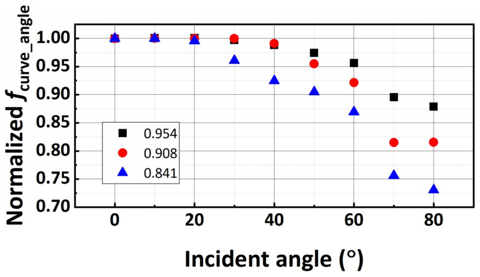
Figure 6 shows the incident angle dependence of fcurve (fcurve_angle) in the cases of Apropjected/Acurve surface = 0.841, 0.908, and 0.954. Only one angle was applied to the light source for the calculation of the fcurve_angle. The values of fcurve_angle were normalized by dividing the ratio of Aprojected to Acurved surface. This means that the ratio of Abscurved surface to Absprojected is indicated in Figure 6, and is shown in Equation (2). The vertical incident angle was set to 0°. The normalized fcurve_angle decreased with the increasing incident angle. In the case of Aprojected/Acurved surface = 0.841 (large curvature shape), the incident angle exceeding 30° resulted in a large decline in fcurve_angle. In contrast, low curvature shapes resulted in fcure_angle being maintained at over 90% at an incident angle of 60°. Masuda et al. [7] reported that an incident angle of solar radiation from 30° to 60° is highly efficient for PV panels mounted on a car roof. To increase the interception of solar radiation by curved PV modules mounted on car roofs, the design of the shape of the roof, including its curvature, will be critical.
5. Conclusions
We proposed a new and simple approach to the characterization of three-dimensionally curved PV modules illuminated by three-dimensional solar irradiance, using a conversion factor that takes into account the influence of three-dimensional effects. The annual irradiance absorbed by car roofs must be accurately evaluated. The curve-correction factor, which is a unique value depending on the three-dimensional curvature of the car-roof PV module, is defined in this paper. The curve-correction factor was calculated using a ray-trace simulator. The shape of the curved PV module affected the curve-correction factor. The ratio of Aprojected to Acurved surface of most car roofs is 0.85–0.95, and fcurve_annual lies between 0.70 and 0.90. The annual irradiance absorbed by car roofs was evaluated using the MPPA system for one year (from September 2017 to August 2018). It is estimated that the effective annual solar radiation for the curved PV module was 2.53–3.52 kWh m−2/day. The effective annual irradiance on the car roof depends on the location and weather. In the case of high curvature shapes, the incident angle exceeding 30° significantly reduced fcurve_angle. In contrast, in the cases of low curvature shapes, a normalized fcure_angle was maintained at over 90% at an incident angle of 60°. To increase the interception of solar radiation by curved PV modules mounted on car roofs, the design of the shape of the roof, including its curvature, is critical.
Author Contributions
Conceptualization: Y.O., T.M., and A.K.; Methodology: A.K. and M.Y.; Validation: A.K. and M.Y.; Formal analysis: Y.O.; Data curation, Y.O.; Writing—Original Draft Preparation, Y.O. and A.K.; Writing—Review & Editing: Y.O.; Supervision: Y.O.
Funding
This work was supported in part by a grant for Scientific Research on Priority Areas from the University of Miyazaki.
Conflicts of Interest
The authors declare that there is no conflict of interest.
References
- Birnie, D.P. Solar-to-vehicle (S2V) systems for powering commuters of the future. J. Power Sour. 2009, 186, 539–542. [Google Scholar] [CrossRef]
- Pantoš, M. Stochastic optimal charging of electric-drive vehicles with renewable energy. Energy 2011, 36, 6567–6576. [Google Scholar] [CrossRef]
- Denholm, P.; Kuss, M.; Margolis, R.M. Co-benefits of large scale plug-in hybrid electric vehicle and solar PV deployment. J. Power Sour. 2013, 236, 350–356. [Google Scholar] [CrossRef]
- Nguyen, T.-T.; Kim, H.W.; Lee, G.H.; Choi, W. Design and implementation of the low cost and fast solar charger with the rooftop PV array of the vehicle. Sol. Energy 2013, 96, 83–95. [Google Scholar] [CrossRef]
- Birnie, D.P. Analysis of energy capture by vehicle solar roofs in conjunction with workplace plug-in charging. Sol. Energy 2016, 125, 219–226. [Google Scholar] [CrossRef]
- Saitoh, T.S.; Yamada, N.; Ando, D.; Kurata, K. A grand design of future electric vehicle to reduce urban warming and CO2 emissions in urban area. Renew. Energy 2005, 30, 1847–1860. [Google Scholar] [CrossRef]
- Masuda, T.; Araki, K.; Okumura, K.; Urabe, S.; Kudo, Y.; Kimura, K.; Nakado, T.; Sato, A.; Yamaguchi, M. Static concentrator photovoltaics for automotive applications. Sol. Energy 2017, 146, 523–531. [Google Scholar] [CrossRef]
- Automotive News, Next-Generation Toyota Prius Has Solar Roof for Europe, Japan. Available online: http://www.autonews.com/article/20160616/OEM05/160619900/next-generation-toyota-prius-has-solar-roof-for-europe-japan (accessed on 30 August 2018).
- Green, M.A.; Hishikawa, Y.; Dunlop, E.D.; Levi, D.H.; Hohl-Ebinger, J.; Ho-Baillie, A.W.Y. Solar cell efficiency tables (version 52). Prog. Photovolt. 2018, 26, 427–436. [Google Scholar] [CrossRef]
- Yang, W.S.; Noh, J.H.; Jeon, N.J.; Kim, Y.C.; Ryu, S.; Seo, J.; Seok, S.I. High-performance photovoltaic perovskite layers fabricated through intramolecular exchange. Science 2015, 348, 1234–1237. [Google Scholar] [CrossRef] [PubMed]
- Chirila, A.; Reinhard, P.; Pianezzi, F.; Bloesch, P.; Uhl, A.R.; Fella, C.; Kranz, L.; Keller, D.; Gretener, C.; Hagendorfer, H.; et al. Potassium-induced surface modification of Cu(In,Ga)Se2 thin films for high-efficiency solar cells. Nat. Mater. 2013, 12, 1107–1111. [Google Scholar] [CrossRef] [PubMed]
- Zortea, L.; Nishiwaki, S.; Weiss, T.P.; Haass, S.; Perrenoud, J.; Greuter, L.; Feurer, T.; Palaniswamy, G.; Buecheler, S.; Tiwari, A.N. Cu(In,Ga)Se2 solar cells on low cost mild steel substrates. Sol. Energy 2018, in press. [Google Scholar] [CrossRef]
- Takamoto, T.; Washio, H.; Juso, H. Application of InGaP/GaAs/InGaAs triple junction solar cells to space use and concentrator photovoltaic. In Proceedings of the 2014 IEEE 40th Photovoltaic Specialist Conference (PVSC), Denver, CO, USA, 8–13 June 2014; pp. 1–5. [Google Scholar] [CrossRef]
- Sasaki, K.; Agui, T.; Nakaido, K.; Takahashi, N.; Onitsuka, R.; Takamoto, T. Development of InGaP/GaAs/InGaAs inverted triple junction concentrator solar cells. AIP Conf. Proc. 2013, 1556, 22–25. [Google Scholar]
- Ota, Y.; Ueda, K.; Takamoto, T.; Nishioka, K. Output evaluation of a world’s highest efficiency flat sub module with InGaP/GaAs/InGaAs inverted triple-junction solar cell under outdoor operation. Jpn. J. Appl. Phys. 2018, 57, 08RD08. [Google Scholar] [CrossRef]
- Imaizumi, M.; Takamoto, T.; Kaneko, N.; Nozaki, Y.; Ohshima, T. Qualification test results of IMM triple-junction solar cells, space solar sheets, and lightweight&compact solar paddle. E3S Web Conf. 2017, 16, 03012. [Google Scholar] [CrossRef]
- Petter Jelle, B.; Breivik, C.; Drolsum Røkenes, H. Building integrated photovoltaic products: A state-of-the-art review and future research opportunities. Sol. Energy Mater. Sol. Cells 2012, 100, 69–96. [Google Scholar] [CrossRef] [Green Version]
- Azadian, F.; Radzi, M.A.M. A general approach toward building integrated photovoltaic systems and its implementation barriers: A review. Renew. Sustain. Energy Rev. 2013, 22, 527–538. [Google Scholar] [CrossRef] [Green Version]
- Ota, Y.; Masuda, T.; Araki, K.; Yamaguchi, M. A mobile multipyranometer array for the assessment of solar irradiance incident on a photovoltaic-powered vehicle. Sol. Energy 2018. submitted for publication. [Google Scholar]
- ISO 9060 Solar Energy—Specification and Classification of Instruments for Measuring Hemispherical Solar and Direct Solar Radiation; International Organization for Standardizaiton (ISO): Geneva, Switzerland, 1990.
- Itagaki, A.; Okamura, H.; Yamada, M. Preparation of meteorological data set throughout japan for suitable design of PV systems. In Proceedings of the 3rd World Conference on Photovoltaic Energy Conversion, Osaka, Japan, 11–18 May 2003; Volume 2, pp. 2074–2077. [Google Scholar]
Figure 1.
A mobile multipyranometer array (MMPA) system.

Figure 2.
Annual irradiance density (AID) model on a horizontal plane, which was defined by the standard dataset, METPV11, from 47 capitals of the prefecture in Japan.
Figure 2.
Annual irradiance density (AID) model on a horizontal plane, which was defined by the standard dataset, METPV11, from 47 capitals of the prefecture in Japan.

Figure 3.
Schematic illustration of the curved surface in this model.

Figure 4.
(a) Irrx+, Irrx−, Irry+, Irry−, and Irrroof measured by the MMPA system. In this case, the car with the MMPA system traveled from the University of Miyazaki to the Miyazaki station; (b) The route from the University of Miyazaki to the Miyazaki station. The actual distance traveled was approximately 15 km.

Figure 5.
fcurve_annual as a function of Apropjected/Acurved surface. Curve shapes corresponding to Aprojected/Acurve-surface = 0.841, 0.908, and 0.954 are also shown, respectively, and are plotted as solid red circles in the graph.
Figure 5.
fcurve_annual as a function of Apropjected/Acurved surface. Curve shapes corresponding to Aprojected/Acurve-surface = 0.841, 0.908, and 0.954 are also shown, respectively, and are plotted as solid red circles in the graph.

Figure 6.
Normalized fcurve_angle as a function of an incident angle.


Table 1.
Specifications of the pyranometers.
| Specifications | SR03 | MS-602 |
|---|---|---|
| ISO classification (ISO 9060:1990 [20]) | Second class | Second class |
| Response time (95%) | <3 s | <17 s |
| Non-linearity (100 to 1000 W m−2) | < ±1% | < ±1.5% |
| Spectral selectivity (0.35 to 1.5 × 10⁻⁶ m) | < ±5% | < ±1% |
| Temperature response (−10 to +40 °C) | < ±3% | <2% |
| Tilt response (0 to 90° at 1000 W m−2) | < ±2% | < ±2% |
Table 2.
Average daily irradiances of the car’s roof, its side, and its front and rear. The measurement period was from September 2017 to August 2018. The average daily irradiance of the horizontal surface is also shown.
Table 2.
Average daily irradiances of the car’s roof, its side, and its front and rear. The measurement period was from September 2017 to August 2018. The average daily irradiance of the horizontal surface is also shown.
| Surface | Average Daily Irradiance (kWh m−2/day) |
|---|---|
| Car roof | 3.61 |
| Car side (Irrx+, Irrx−) | 3.28 |
| Car front and rear (Irry+, Irry−) | 3.03 |
| Horizontal (for comparison) | 3.90 |
© 2018 by the authors. Licensee MDPI, Basel, Switzerland. This article is an open access article distributed under the terms and conditions of the Creative Commons Attribution (CC BY) license (http://creativecommons.org/licenses/by/4.0/).
Share and Cite
MDPI and ACS Style
Ota, Y.; Masuda, T.; Araki, K.; Yamaguchi, M. Curve-Correction Factor for Characterization of the Output of a Three-Dimensional Curved Photovoltaic Module on a Car Roof. Coatings 2018, 8, 432. https://doi.org/10.3390/coatings8120432
AMA Style
Ota Y, Masuda T, Araki K, Yamaguchi M. Curve-Correction Factor for Characterization of the Output of a Three-Dimensional Curved Photovoltaic Module on a Car Roof. Coatings. 2018; 8(12):432. https://doi.org/10.3390/coatings8120432
Chicago/Turabian StyleOta, Yasuyuki, Taizo Masuda, Kenji Araki, and Masafumi Yamaguchi. 2018. "Curve-Correction Factor for Characterization of the Output of a Three-Dimensional Curved Photovoltaic Module on a Car Roof" Coatings 8, no. 12: 432. https://doi.org/10.3390/coatings8120432
Note that from the first issue of 2016, this journal uses article numbers instead of page numbers. See further details here.