Article

Comparison of Corrosion Resistance and Cytocompatibility of MgO and ZrO2 Coatings on AZ31 Magnesium Alloy Formed via Plasma Electrolytic Oxidation

1
School of Stomatology, Lanzhou University, Lanzhou 730000, China
2
State Key Laboratory of Solid Lubrication, Lanzhou Institute of Chemical Physics, Chinese Academy of Sciences, Lanzhou 730000, China
*
Authors to whom correspondence should be addressed.
Coatings 2018, 8(12), 441; https://doi.org/10.3390/coatings8120441
Submission received: 25 October 2018 / Revised: 24 November 2018 / Accepted: 27 November 2018 / Published: 30 November 2018

Abstract

:
In this work, one coating is comprised of ZrO2 and the other consists of MgO as main phase composition was produced on AZ31 magnesium alloy using one-step plasma electrolytic oxidation (PEO). The purpose of this work was to study the corrosion resistance and cytocompatibility of the above-coated AZ31 magnesium alloys in order to provide a basis for AZ31 Mg alloy’s clinical applications of biomedical use. The morphology and phase composition of the coatings were studied using scanning electron microscopy (SEM) and X-ray diffraction (XRD). The corrosion properties were examined using electrochemical testing, hydrogen evolution measurements, and immersion tests in a simulated body fluid (SBF). Compared with bare magnesium and the MgO coating, the ZrO2-containing coating exhibited an improved corrosion resistance. Cell proliferation assays and cell morphology observations showed that the ZrO2-containing coating was not toxic to the L-929 cells. The ZrO2 coating was much denser and more homogeneous than the MgO coating, hence the corrosion resistance of the ZrO2-coated AZ31 Mg alloy was superior and more stable than the MgO-coated AZ31 Mg alloy, and ZrO2/AZ31 did not induce a cytotoxic reaction to L-929 cells and promote cell growth.

1. Introduction

Metallic biomaterials refer to the metal-based materials used to make biological materials. Metallic biomaterials are widely used in dentistry, orthopedics, and cardiovascular medicine, and play an important role in implant applications due to their good mechanical and processing properties, and their biological stability [1,2,3]. Stainless steel, cobalt-based alloys, titanium, and titanium alloys are the most frequently used materials in the medical applications in the last few decades. However, closer inspection reveals that there are many disadvantages regarding their use, such as the stress-shielding effect, where the elastic modulus of the metal implantation does not match the host bone, and the mechanical shunt of the former results in the reduction of strength of the surrounding bone or causes delayed healing of bone tissue. In addition, the materials corrode in the human environment, releasing toxic corrosion products, which cause local inflammation and other problems. Moreover, these produced materials cannot be degraded, so they need to be removed during a second surgery [4]. Not only does this increase the chances of infection, but it also increases the financial burden on both the patient and/or the healthcare system. In recent years, biodegradable biomaterials for medical use have gained significant interest and have been extensively investigated. Magnesium alloy has been suggested as a revolutionary biodegradable metal for use as an orthopedic material due to its advantageous properties, such as high biodegradability and recoverability, lightweight nature, good mechanical strength, and good resistance against electromagnetic waves. Particularly, the elastic modulus of magnesium is similar to natural bone tissue and can prevent the occurrence of stress-shielding effects to facilitate the healing of bone tissue [5,6]. One of the first clinical applications of pure magnesium implants was in 1906 by Lambotte. However, this attempt was unsuccessful due to extensive gas cavities, local swelling, and significant pain experienced by the patient [7]. At present, this problem still limits the clinical application of magnesium alloy as a biodegradable biomaterial. Erinc proposed the following standards for biodegradable medical magnesium alloys: (1) the corrosion rate is less than 0.5 mm·a−1 in simulated body fluids at 37 °C, (2) the effective service period is ≈90–180 days, and (3) at room temperature the yield strength is greater than 200 MPa and the elongation rate is greater than 15% [8]. Unfortunately, the major limitations of Mg alloys are they are chemically active and, therefore, have unsatisfactory corrosion properties [9,10,11].
The surface modification of magnesium alloy is one of the methods used to solve its poor corrosion resistance. Different surface modification methods have been mentioned in the literature, such as biomineralization [12], laser surface melting (LSM) [13], the sol-gel method [14], plasma electrolytic oxidation (PEO) [10,11], and others. Among all the surface modification methods, this study selected plasma electrolytic oxidation to improve the performance of AZ31 magnesium alloy. This method was chosen because plasma electrolytic oxidation can produce a relatively dense and well-adhering coating, while being a rather inexpensive and environmentally friendly technique [15,16,17,18]. In recent years, many studies have explored the properties of micro-arc zirconia oxide film. Liang et al. [19] suggested that, in a 3.5 wt % NaCl solution, and when compared to MgO-coated AM50, ZrO2-coated AM50 can provide a much more stable corrosion resistance over a longer period of time. Liu et al. [20] developed a novel K2ZrF6 electrolyte solution and studied its composition, structure, and the elemental distribution of the coating, then explored its deterioration processes. Mu et al. [21] reported that a MgF2/ZrO2 coating greatly improved the corrosion resistance of magnesium. Meanwhile, researchers have been concerned about the application of zirconia in biology for a long time. Chen et al. [22] indicated that after soaking in simulated body fluid, ZrO2 ceramic coating treated in the zirconium electrolyte can induce the formation of hydroxyapatite bio-ceramics, thus further improving the bone biological activity of the coating. Meanwhile, many other investigators have indicated that ZrO2 coating, especially monoclinic ZrO2, can enhance implant osseointegration [23,24]. According to Schultzemosgau et al. [25], the biocompatibility of ZrO2 was similar to that of titanium.
However, although AZ31 magnesium is a medical-grade magnesium alloy, the long-term corrosion resistance of ZrO2-coated AZ31 magnesium alloy in simulated body fluid, and the cytocompatibility of ZrO2-coated AZ31 magnesium alloy, are seldom reported. Chen et al. [22] studied the long-term immersion test of the ZrO2-coated magnesium and Depprich et al. [26] studied the behavior of osteoblastic cells cultured on ZrO2. In this study, the stability of ZrO2-coated AZ31 magnesium alloy in simulated body fluids was investigated along with its cytocompatibility with the hope of providing a basis for AZ31 Mg alloy’s clinical applications for biomedical use.

2. Materials and Methods

2.1. Specimen and Plasma Electrolytic Oxidation (PEO) Treatment

Specimens of 20 mm × 20 mm × 10 mm were cut from an AZ31 magnesium alloy sheet (Hongxing Metal Materials Co., Ltd., Dongguan, China). Before plasma electrolytic oxidation (PEO) treatment, the samples were ground and polished using SiC papers (up to 1500 grit), then ultrasonically cleaned with acetone for degreasing and dried in warm air. The PEO device (WHYH-20, Beijing Normal University, Beijing, China) was composed of a 20 kW DC power supply, with AZ31 Mg alloy substrates used as anodes and a stainless-steel bath containing electrolyte used as the cathode. The experiment was divided into three groups: AZ31 magnesium alloy treated as the blank group, MgO-containing coating samples identified as the control group, and ZrO2-containing coating samples regarded as the experimental group. The electrolyte concentration and the experimental parameters during the PEO process are shown in Table 1. Throughout the experiment, the temperatures of the electrolytes were maintained below 25 °C using a water circulation system. After PEO treatment, all coated samples were rinsed thoroughly in distilled water and dried in warm air.

2.2. Microstructural and Phase Composition

The thickness of the coatings was measured using a digital eddy current thickness gauge (1100, Elcktrophysic, Cologne, Germany). Surface and cross-sectional morphologies of coatings were observed using a scanning electron microscope (SEM, nSM-5600LV, JEOL, Tokyo, Japan) equipped with an energy dispersive X-ray spectrometer (Energy dispersive spectrometer (EDS), Hitachi S-4800, Hitachi, Ltd., Tokyo, Japan). Phase composition of the coatings was examined using X-ray diffraction (XRD, D/Max-2400, Rigaku Co., Ltd., Tokyo, Japan) with Cu-Kα radiation, test angles (2θ) from 20° to 80°, a test voltage of 40 kV, a current of 150 mA, and a step size of 0.02°.

2.3. Corrosion Test

2.3.1. Electrochemical Experiments

To evaluate the corrosion characteristics of AZ31 magnesium alloy and PEO coatings, potentiodynamic polarization and electrochemical impedance spectroscopy (EIS) tests were carried out in simulated body fluid (SBF) using an electrochemical workstation (Autolab PGSTAT302N, Metrohm, the Netherlands) with a conventional three-electrode setup: specimens as working electrodes, the Ag/AgCl (saturated with KCl) as the reference electrode, and a platinum mesh as the counter electrode. The samples had an exposed area of 0.5 cm2 and were immersed in SBF. After an initial delay of 30 min to stabilize the open-circuit potential (OCP), the constant scan rate was 1 mV·s−1. The EIS tests were measured at an open circuit potential in the frequency range of 0.01 to 30000 Hz with an alternating current (AC) signal amplitude of 10 mV; the measurements were made after 0.5, 2, 5, 20, 112, and 160 h. The Z-view2 (Version 2.9c, Scribner Associates, Southern Pines, NC, USA) software was used to analyze the results. The electrochemical corrosion tests were performed in triplicate to evaluate the reproducibility of the results.

2.3.2. Long-Term Immersion Tests

In this test, the samples were suspended in a 1 L beaker containing SBF maintained at 37.5 °C in a thermostatic bath. The corrosion resistance of the specimens was evaluated by the length of time before the occurrence of local corrosion on the surface of these samples. The test solution was renewed every 24 h.
The corrosion rate was measured via hydrogen evolution. The test was performed in triplicate to evaluate the reproducibility of the results.

2.4. Cytotoxicity and Cell Morphology Examination

Cytotoxicity of the samples was tested using L-929 cells, which were cultured with RPMI-1640 at 37 °C under an atmosphere of 5% CO2 in a humidified incubator. The RPMI-1640 was supplemented with 10% (v/v) fetal bovine serum and 1% (v/v) streptomycin and penicillin. The extraction medium was prepared with RMPI-1640 at an extraction ratio of 0.5 cm2·mL−1. Cells were seeded at a concentration of 2.5×10³ cells·mL−1 in 96-well plates and cultured for 24 h. Then, the culture medium was replaced by the extraction medium excepting the cytotoxicity negative group which was represented by L-929 cells cultured in RMPI-1640. Then, the culture medium was replaced by the extraction medium. The percentage of cell viability was quantitatively determined using an MTT [3-(4,5-dimethylthiazole-2-yl)-2,5-diphenyl tetrazolium bromide] assay. The absorbance was measured at 490 nm using a microplate reader (Elx 800, Bio-Tek, Winooski, VT, USA). This method was used after 1, 4, and 7 days of culturing. The assay was independently repeated three times. The data were subjected to an unpaired single-tailed Student’s test. A value of p < 0.05 was considered significant. The cell morphology was observed by an inverted optical microscope (IX2-Olympus, Tokyo, Japan).

3. Results and Discussion

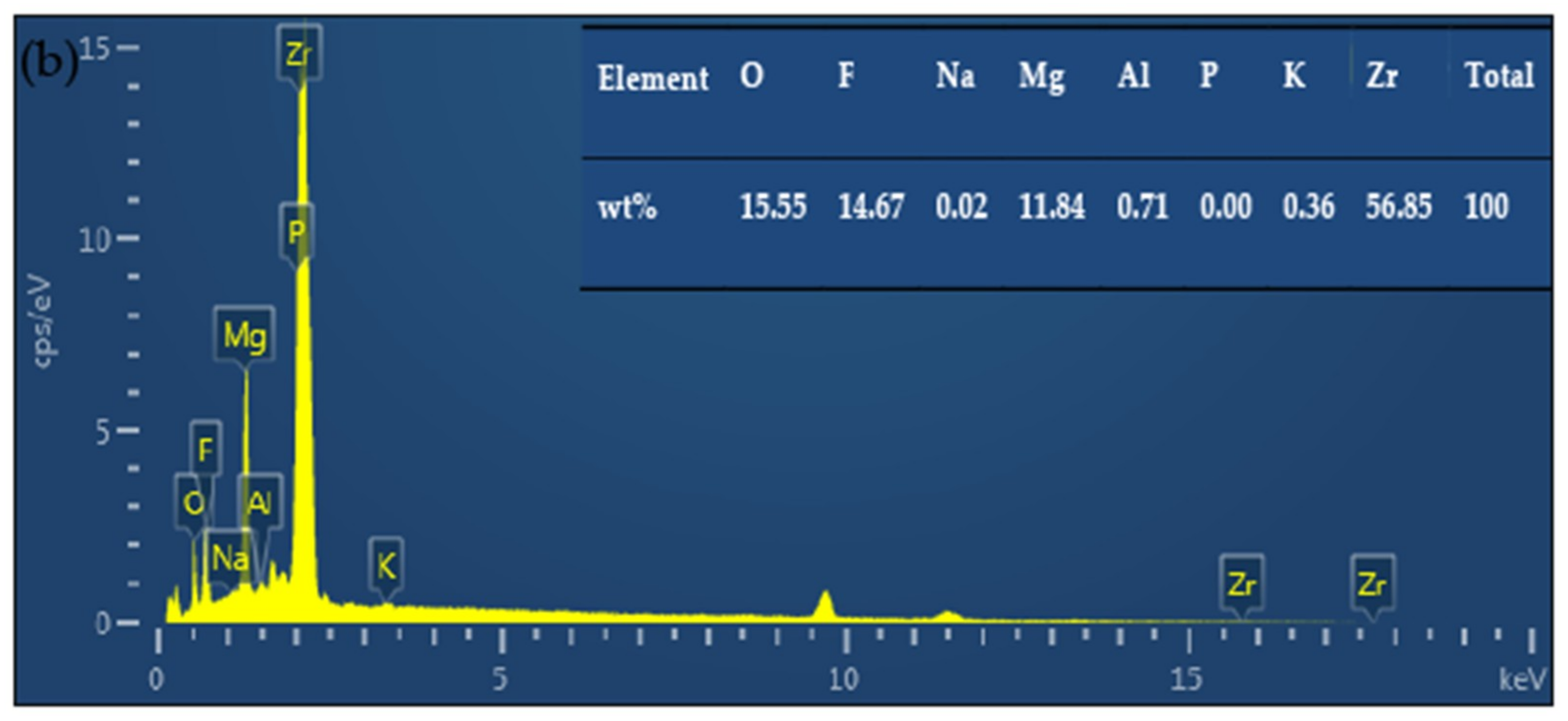
3.1. Phase Composition

Figure 1 shows the X-ray diffraction (XRD) patterns of the coated samples. As shown in Figure 1a, three strong and clear peaks are present representing MgO [27], suggesting that the PEO coating produced in the conventional phosphate electrolyte consisted mainly of MgO (addressed as “MgO” coating). Figure 1b shows the coating produced in the fluorozirconate electrolytes. Normally, the characteristic peaks of ZrO2 appear at 30.4°, 35.2°, 50.4°, and 60.3° [19,20,21,22,23]. It can be seen from Figure 1b that the characteristic peaks of t-ZrO2 and m-ZrO2 phases were evident (addressed as “ZrO2” coating), with the results in accordance with Luo et al. [28] and most of the literature. Meanwhile, a few peaks relating to MgO and MgF2 were also detected, which indicated that zirconium oxides are the major constituents of this coating. The peaks corresponding to t-ZrO2 and m-ZrO2 indicated that fluorozirconate from the electrolyte participated in the plasma-thermo-chemical reactions during the PEO process and were incorporated into the coatings as compounds. In both of the PEO coatings, the diffraction peaks corresponding to the Mg alloy substrate were detected.

3.2. Surface and Cross-Section Microstructure

Figure 2 presents the surface and cross-section morphologies of the ceramic coatings formed in the two different electrolytes. The coating obtained in the conventional phosphate electrolyte consisted of typical PEO coating defects, such as pores and cracks (Figure 2a,b), with some of the micropores being filled with coating compounds. These pores were formed by the molten oxide and gas bubbles, which emitted out of the arc discharge channels during the PEO process. The microcracks were caused by excess thermal stress during the fast solidification of the melts when the coatings surface come in contact with the electrolytic solutions [29,30]. However, the coating formed in the fluorozirconate electrolytes was much more homogeneous than the conventional one (Figure 2c,d), suggesting that the high concentration of K2ZrF6 was beneficial for removing the large-size pores in the coating [31]. Additionally, it is clear that this coating contained numerous snowflake cluster particles due to the potassium fluorozirconate electrolyte not being stable when its pH was alkaline or too acidic in the electrolysis process. The deposition precipitated in the electrolyte with the general formula [ZrOx(OH)4−2x·yH2O]n and was responsible for the appearance of snowflake cluster particles [32].
The cross-sectional morphologies of the coatings are shown in Figure 3. Figure 3a,b reveals that the MgO coating was composed of an outer porous layer and an inner barrier layer. The average thickness of this coating was about 17 ± 2 μm. There were several different sizes of pores and some cracks straight through the coating. On the other hand, unlike the MgO coating, the ZrO2 coating seemed homogeneous and compact (Figure 3c,d), with the thickness of the coating being about 12 ± 2 μm. Even though this coating was thinner than the MgO coating, no obvious micropores were observed.
Figure 4 shows the elemental distribution of the PEO coatings detected using EDS scans. The elements O, Mg, P, and trace amounts of F were detected in the MgO coating (Figure 4a). For the ZrO2 coating, elemental O, F, Mg, P, and Zr were present throughout the coating (Figure 4b). In addition, the concentration of Zr was quite high, while the concentrations of other elements were relatively low.

3.3. Corrosion Studies

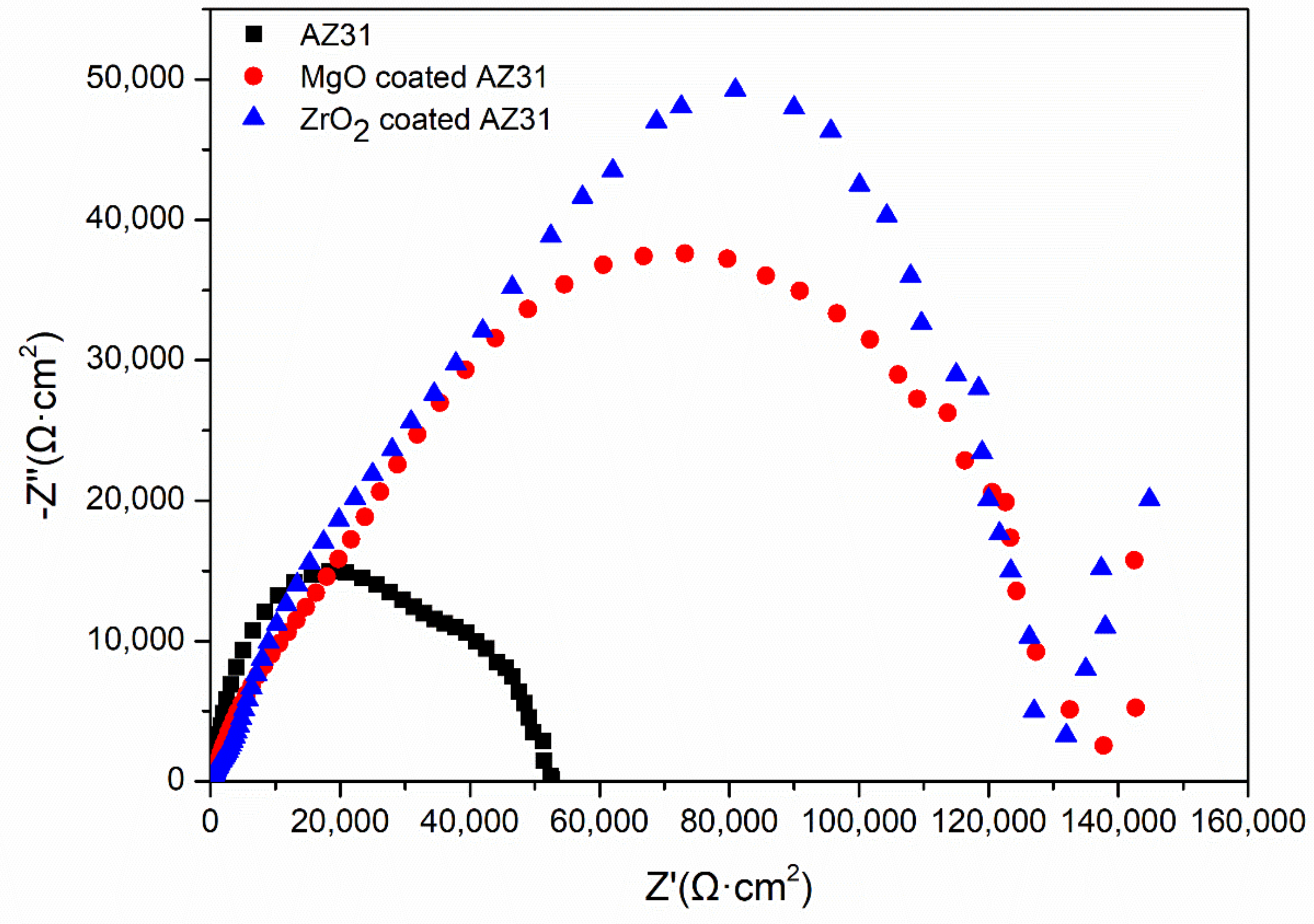
3.3.1. Electrochemical Measurements

The polarization curves of the coatings and bare sample in SBF are shown in Figure 5 with the associated electrochemical data listed in Table 2. The corrosion potential (Ecorr) of the ZrO2 coating was −1.3911 V, which was higher than that of MgO/AZ31 (−1.4174 V) and AZ31 magnesium alloy (−1.4689 V). The corresponding corrosion current densities (Icorr) are 1.5072 × 10⁻⁷ A·cm−2, 3.5754 × 10⁻⁷ A·cm−2, and 1.8895 × 10⁻⁶ A·cm−2 for the ZrO2 coating, MgO coating, and uncoated AZ31 magnesium alloy, respectively. Compared with the AZ31 Mg alloy, the Ecorr of the ZrO2 coating shifted about 77.8 mV in the positive direction, while its Icorr decreased one order of magnitude compared to the uncoated AZ31 Mg alloy, suggesting that the ZrO2 coating significantly promoted the corrosion resistance of AZ31 magnesium alloy. The determined Icorr of 1.5072 × 10⁻⁷ A·cm−2 is comparable to ZrO2 coatings obtained in other fluorozirconate electrolytes [27,28,29]. Moreover, these results indicated that the corrosion resistance of the ZrO2 coating is close to that of the MgO coating in a short time.
The corrosion behaviors of the uncoated and the PEO-coated AZ31 Mg alloys in SBF were further studied using EIS tests. A Nyquist plot is shown in Figure 6. It is clear that both the uncoated and coated samples are characterized by a capacitive loop in the high frequency range. Hu et al. [33] reported a capacitive reactance arc of coated specimens that showed that the electrochemical reaction area of coating and metal interface is small during soaking. Nevertheless, the corrosion rate of these three groups was evidently different due to the different radius of the capacitive loop. In other words, the bigger the radius of capacitive loop is, the lower the corrosion rate of the coating. Thus, according to the plot, ZrO2-coated AZ31 magnesium alloy has a better corrosion resistance than both the MgO-coated AZ31 Mg alloy and the bare magnesium alloy.
To further understand the long-term corrosion behavior of the coated AZ31 magnesium alloy in SBF, electrochemical measurements were employed. Figure 7 shows the resulting Bode plots of the coated AZ31 alloys after 0.5, 2, 5, 20, 112, and 160 h of exposure in SBF. When there was no local corrosion of the sample, there contained two time constants, seen in Figure 7b,d. Analysis of these Bode plots suggests that an equivalent circuit model was required to fit the results. In equivalent circuits, Rs is the solution resistance, R1 is the resistance of the PEO coating paralleled with constant phase element (CPE)1, and R2 is the coating/substrate interface resistance in parallel with (CPE)2 [34]. The values of the fitted circuit elements are summarized in Table 3 and Table 4. After the initial 0.5 h of immersion, both of the coatings exhibited much higher R2 values than R1, suggesting that the corrosion protection of the coatings mainly depended on the dense inner layer.
For MgO coating, during the first 5 h of immersion, both the R1 and R2 values decreased, especially the value of R1, which reduced by two orders of magnitude and showed that the loose outer layer basically lost its protective effect on the substrate. After soaking for 20 h, R1 slightly increased. This was because the MgO reacted with water to form Mg(OH)2. The molar volume of Mg(OH)2 is greater than MgO, which reduces defects in the coating to a certain extent and thereby increases the corrosion resistance of the outer layer [35]. After 160 h of immersion, an apparent inductive arc appeared in Figure 7b, indicating that the coating had been partially broken.
For the ZrO2 coating, after 5 h of immersion, both the values of R1 and R2 slightly decreased and the rate of reduction was quite moderate compared to the MgO coating. After soaking for 20 h, the R1 and R2 values remained relatively stable. During the whole process, while the two R2 values were close, there were much greater differences between the two R1 values. The results show that the ZrO2/AZ31 coating was relatively uniform and stable. This may be due to, after immersion in SBF, the outer layer forming calcium and phosphorus deposits, temporarily improving the protection of the substrate [22].

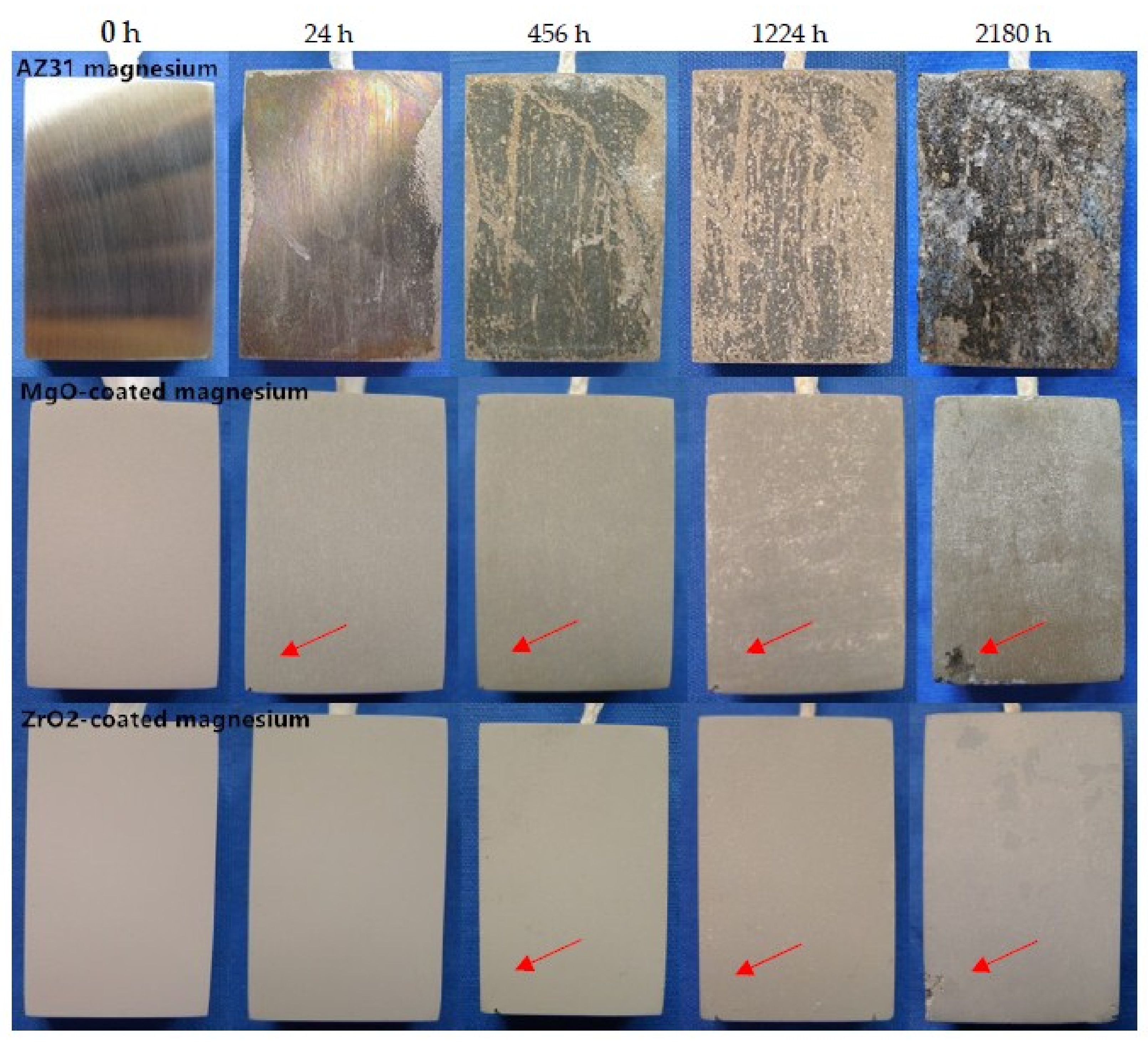
3.3.2. Long-Term Immersion Test

Photographs taken of the various samples after an immersion test in SBF at different time intervals are shown in Figure 8. From the images, the surface of the uncoated AZ31 magnesium alloy had already experienced corrosion after 24 h of immersion. However, both of the coated samples did not show obvious signs of corrosion under the same conditions. The macroscopic photograph depicted in Figure 8 shows that the MgO coating suffered localized corrosion damage after 24 h of immersion in SBF. In the case of the ZrO2 coating, however, the corroded area appeared after immersion for 456 h in SBF. Finally, both of the coatings showed even more corrosion damage regions when the immersion time reached 2180 h. The results show that the ZrO2 coating provided longer protection times than the MgO coating. This observation was in good agreement with the electrochemical analysis results.

3.3.3. Hydrogen Evolution Tests

Hydrogen evolution testing in SBF was conducted at 37 °C using an oil bath with an inverted funnel-burette type system, as described previously [36]. Each sample was soaked in a solution for a total of 5 days. The volume of H2 was recorded every 3 h for the first day, every 6 h for the second day, and every 24 h for the remaining three days. The average value of three measurements was used as the final result for each sample. Figure 9 presents the results of the H2 evolution test of the uncoated AZ31 Mg alloy and the coated samples immersed in SBF for 5 days at 37 °C. The total H2 evolution of the uncoated AZ31 Mg alloy, which was 32.7 mL after 5 days, showed the highest corrosion rate. In comparison, the accumulated H2 evolution volume of the MgO-coated AZ31 decreased to about 9 mL. The accumulated H2 evolution volume of the ZrO2-coated AZ31 further decreased to about 8.5 mL. As shown in Figure 9b, the bare AZ31 magnesium alloy had the highest corrosion rate during the immersion, while the MgO-coated AZ31 and the ZrO2/AZ31 displayed H2 evolution rates of 0.2 and 0.18 mL·cm−2·day−1, respectively. This suggests that both the MgO and the ZrO2 coatings can protect the AZ31 Mg alloy in SBF, with the ZrO2 coating showing a better barrier property. These results are consistent with former electrochemical data and immersion tests.

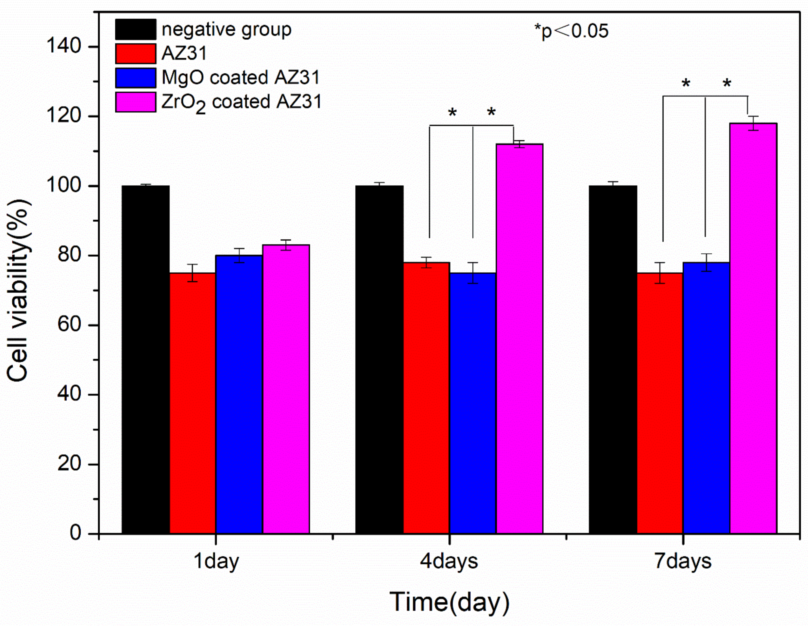
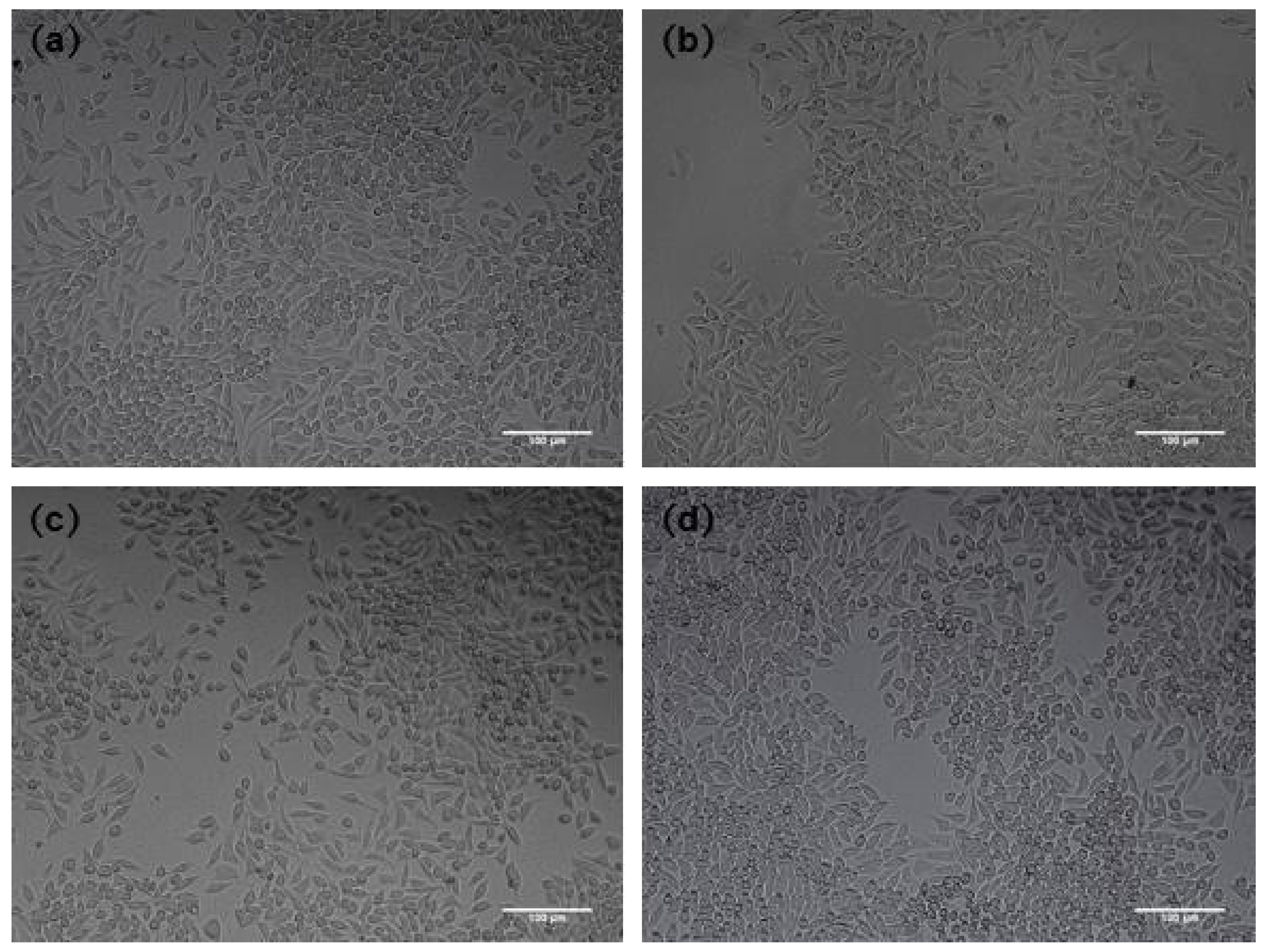
3.4. Cytotoxicity Test

The cell viability results from the MTT tests assessing the cytotoxicity of AZ31, MgO-coated AZ31, and ZrO2-coated AZ31 are shown in Figure 10. The L-929 cell viability cultured with the extracts of ZrO2-coated AZ31 for the first day was close to those of MgO-coated AZ31 and uncoated AZ31. However, the viabilities of L-929 cells cultured with the extract media of ZrO2-coated AZ31 for 4 and 7 days were much higher than those of MgO-coated AZ31 and uncoated AZ31, with the differences between ZrO2-coated AZ31 and MgO-coated AZ31, ZrO2-coated AZ31, and uncoated AZ31 being statistically significant. In addition, the cell viability of the ZrO2/AZ31 specimen increased during the cultivation process, and the value almost reached 120% in the seventh day, which showed that these coated samples are non-toxic. It was reported that a zirconia coating can induce apatite precipitation in modified SBF [37].
Figure 11 shows the morphologies of the L-929 cells cultured in the extraction medium from (a) negative control, (b) AZ31, (c) MgO-coated AZ31, and (d) ZrO2-coated AZ31 for 7 days. It is obvious from the image that the cells cultured in the ZrO2-coated AZ31 were clearly greater in viability than those incubated in other groups. In particular, cell morphologies in the extracts of the ZrO2-coated AZ31 were normal and healthy, similar to those of the negative control group. This result shows that the ZrO2 coating had good proliferation, suggesting that the material was not toxic to cells and was suitable for cell growth.

4. Conclusions

The MgO- and ZrO2-containing ceramic coatings formed on an AZ31 magnesium alloy were prepared using plasma electrolyte oxidation in a basic phosphate electrolyte solution and in a fluorozirconate electrolyte solution, respectively. The composition, structure, corrosion behavior, and cytotoxicity of the coatings were studied. The following conclusions can be drawn:
  • The coating formed in the basic phosphate electrolyte was porous and mainly composed of MgO and MgF2, while the coating formed in fluorozirconate electrolyte was dense and mainly consisted of t-ZrO2 and m-ZrO2.
  • The corrosion resistance of the ZrO2 coating was superior to that of the MgO coating in the polarization tests after 0.5 h of exposure to the corrosive environment. The long-term EIS tests and the immersion tests revealed the extent of corrosion deterioration of the PEO coatings on the AZ31 Mg alloy exposed to the SBF solution. The deterioration process of both coatings started from a slow corrosion damage of PEO coating and then progressed, finally, to localized corrosion damage of the magnesium alloy substrate. The results indicated that the ZrO2 coating provides a much more stable corrosion-resistant layer than the MgO coating at different immersion times.
  • In-vitro cytotoxicity tests indicated that the ZrO2-coated AZ31 did not induce a cytotoxic reaction to L-929 cells and promoted cell growth during the first 7 days.

Author Contributions

Conceptualization, B.C., J.L.; Software, S.W.; Formal Analysis, S.W., Z.N. and L.F.; Data Curation, S.W.; Writing–Original Draft Preparation, S.W.; Writing–Review & Editing, S.W., L.F., Z.N., B.C. and J.L.

Funding

This work was funded by the Natural Science Foundation of Gansu Province, China (No. 1208RJZA236).

Acknowledgments

We sincerely thank Zhenjun Peng from the State Key Laboratory of Solid Lubrication, Lanzhou Institute of Chemical Physics, Chinese Academy of Sciences for the technical assistance during these studies. We also appreciate the valuable comments provided by other members of our laboratories.

Conflicts of Interest

The authors declare no conflict of interest.

References

  1. Jacobs, J.J.; Gilbert, J.L.; Urban, R.M. Corrosion of metal orthopaedic implants. JBJS 1998, 88, 268–282. [Google Scholar] [CrossRef]
  2. Zhu, B.; Xu, Y.; Sun, J.; Yang, L.; Guo, C.; Liang, J.; Cao, B. Preparation and characterization of aminated hydroxyethyl cellulose-induced biomimetic hydroxyapatite coatings on the AZ31 magnesium alloy. Metals 2017, 7, 214. [Google Scholar] [CrossRef]
  3. Tian, P.; Liu, X. Surface modification of biodegradable magnesium and its alloys for biomedical applications. Regen. Biomater. 2015, 2, 135–151. [Google Scholar] [CrossRef] [PubMed]
  4. Shadanbaz, S.; Dias, G.J. Calcium phosphate coatings on magnesium alloys for biomedical applications: A review. Acta Biomater. 2012, 8, 20–30. [Google Scholar] [CrossRef] [PubMed]
  5. Lin, B.; Zhong, M.; Zheng, C.; Cao, L.; Wang, D.; Wang, L.; Liang, J.; Cao, B. Preparation and characterization of dopamine-induced biomimetic hydroxyapatite coatings on the AZ31 magnesium alloy. Surf. Coat. Technol. 2015, 281, 82–88. [Google Scholar] [CrossRef]
  6. Zhu, B.; Wang, S.; Wang, L.; Yang, Y.; Liang, J.; Cao, B. Preparation of hydroxyapatite/tannic acid coating to enhance the corrosion resistance and cytocompatibility of AZ31 magnesium alloys. Coatings 2017, 7, 105. [Google Scholar] [CrossRef]
  7. Waizy, H.; Seitz, J.M.; Reifenrath, J.; Weizbauer, A.; Bach, F.W.; Meyer-Lindenberg, A.; Denkena, B.; Windhagen, H. Biodegradable magnesium implants for orthopedic applications. J. Mater. Sci. 2013, 48, 39–50. [Google Scholar] [CrossRef]
  8. Erinc, M.; Sillekens, W.H.; Mannens, R.G.T.M.; Werkhoven, R.J. Applicability of existing magnesium alloys as biomedical implant materials. In Proceedings of the Magnesium Technology 2009, San Francisco, CA, USA, 15–19 February 2009. [Google Scholar]
  9. Liu, C.; Liang, J.; Zhou, J.; Wang, L.; Li, Q. Effect of laser surface melting on microstructure and corrosion characteristics of AM60B magnesium alloy. Appl. Surf. Sci. 2015, 343, 133–140. [Google Scholar] [CrossRef]
  10. Liu, C.; Liang, J.; Zhou, J.; Li, Q.; Peng, Z.; Wang, L. Characterization and corrosion behavior of plasma electrolytic oxidation coated AZ91-T6 magnesium alloy. Surf. Coat. Technol. 2016, 304, 179–187. [Google Scholar] [CrossRef]
  11. Liu, C.; Liang, J.; Zhou, J.; Li, Q.; Peng, Z.; Wang, L. Corrosion behavior of plasma electrolytic oxidation coated AZ91 Mg alloy: Influence of laser surface melting pretreatment. RSC Adv. 2016, 6, 70343–70351. [Google Scholar] [CrossRef]
  12. Yang, Y.; Kim, K.H.; Ong, J.L. A review on calcium phosphate coatings produced using a sputtering process—An alternative to plasma spraying. Biomaterials 2005, 26, 327–337. [Google Scholar] [CrossRef] [PubMed]
  13. Wang, L.; Zhou, J.; Liang, J.; Chen, J. Microstructure and corrosion behavior of plasma electrolytic oxidation coated magnesium alloy pre-treated by laser surface melting. Surf. Coat. Technol. 2012, 206, 3109–3115. [Google Scholar] [CrossRef]
  14. Kumar, N.; Subasri, R. Corrosion protection and self-healing by sol-gel process: A review of recent patent literature. Recent Pat. Corros. Sci. 2012, 2, 148–163. [Google Scholar] [CrossRef]
  15. Liu, C.; Liang, J.; Zhou, J.; Li, Q.; Wang, L. Characterization of AZ31 magnesium alloy by duplex process combining laser surface melting and plasma electrolytic oxidation. Appl. Surf. Sci. 2016, 382, 47–55. [Google Scholar] [CrossRef]
  16. Darband, G.B.; Aliofkhazraei, M.; Hamghalam, P.; Valizade, N. Plasma electrolytic oxidation of magnesium and its alloys: Mechanism, properties and applications. J. Magnes. Alloys 2017, 5, 74–132. [Google Scholar] [CrossRef]
  17. Apelfeld, A.; Krit, B.; Ludin, V.; Morozova, N.; Vladimirov, B.; Wu, R.Z. The characterization of plasma electrolytic oxidation coatings on AZ41 magnesium alloy. Surf. Coat. Technol. 2017, 322, 127–133. [Google Scholar] [CrossRef]
  18. White, L.; Koo, Y.; Neralla, S.; Sankar, J.; Yun, Y. Enhanced mechanical properties and increased corrosion resistance of a biodegradable magnesium alloy by plasma electrolytic oxidation (PEO). Mater. Sci. Eng. B 2016, 208, 39–46. [Google Scholar] [CrossRef] [PubMed] [Green Version]
  19. Liang, J.; Srinivasan, P.B.; Blawert, C.; Dietzel, W. Comparison of electrochemical corrosion behavior of MgO and ZrO2, coatings on AM50 magnesium alloy formed by plasma electrolytic oxidation. Corros. Sci. 2009, 51, 2483–2492. [Google Scholar] [CrossRef]
  20. Liu, F.; Shan, D.; Song, Y.; Han, E.H.; Ke, W. Corrosion behavior of the composite ceramic coating containing zirconium oxides on AM30 magnesium alloy by plasma electrolytic oxidation. Corros. Sci. 2011, 53, 3845–3852. [Google Scholar] [CrossRef]
  21. Mu, W.; Han, Y. Characterization and properties of the MgF2/ZrO2, composite coatings on magnesium prepared by micro-arc oxidation. Surf. Coat. Technol. 2008, 202, 4278–4284. [Google Scholar] [CrossRef]
  22. Hong, C.; Jianmin, H. Study on preparing of ZrO2 ceramic coating and bone biological activity of magnesium alloys for medicine. Rare Met. Mater. Eng. 2014, 43, 150–153. [Google Scholar]
  23. Li, J.; Zhang, X.; He, X.; Hang, R.; Huang, X.; Tang, B. Preparation, biocompatibility and wear resistance of microstructured Zr and ZrO2, alloyed layers on 316L stainless steel. Mater. Lett. 2017, 203, 24–27. [Google Scholar] [CrossRef]
  24. Wang, G.; Meng, F.; Ding, C.; Chu, P.K.; Liu, X. Microstructure, bioactivity and osteoblast behavior of monoclinic zirconia coating with nanostructured surface. Acta Biomater. 2010, 6, 990–1000. [Google Scholar] [CrossRef] [PubMed]
  25. Schultze-Mosgau, S.; Schliephake, H.; Radespiel-Tröger, M.; Neukam, F.W. Osseointegration of endodontic endosseous cones: Zirconium oxide vs titanium. Oral Surg. Oral Med. Oral Pathol. Oral Radiol. Endod. 2000, 89, 91–98. [Google Scholar] [CrossRef]
  26. Depprich, R.; Ommerborn, M.; Zipprich, H.; Naujoks, C.; Handschel, J.; Wiesmann, H.P.; Kübler, N.R.; Meyer, U. Behavior of osteoblastic cells cultured on titanium and structured zirconia surfaces. Head Face Med. 2008, 4, 29. [Google Scholar] [CrossRef] [PubMed] [Green Version]
  27. Tang, M.; Liu, H.; Li, W.; Zhu, L. Effect of zirconia sol in electrolyte on the characteristics of microarc oxidation coating on AZ91D magnesium. Mater. Lett. 2011, 65, 413–415. [Google Scholar] [CrossRef]
  28. Luo, H.; Cai, Q.; Wei, B.; Yu, B.; He, J.; Li, D. Study on the microstructure and corrosion resistance of ZrO2-containing ceramic coatings formed on magnesium alloy by plasma electrolytic oxidation. J. Alloy. Compd. 2009, 474, 551–556. [Google Scholar] [CrossRef]
  29. Mu, W.; Yong, H. Study on micro-arc oxidized coatings on magnesium in three different electrolytes. Rare Met. Mater. Eng. 2010, 39, 1129–1134. [Google Scholar]
  30. Zhuang, J.J.; Guo, Y.Q.; Xiang, N.; Xiong, Y.; Hu, Q.; Song, R.G. A study on microstructure and corrosion resistance of ZrO2-containing PEO coatings formed on AZ31 Mg alloy in phosphate-based electrolyte. Appl. Surf. Sci. 2015, 357, 1463–1471. [Google Scholar] [CrossRef]
  31. Liu, F.; Shan, D.; Song, Y.; Han, E.H. Effect of additives on the properties of plasma electrolytic oxidation coatings formed on AM50 magnesium alloy in electrolytes containing K2ZrF6. Surf. Coat. Technol. 2011, 206, 455–463. [Google Scholar] [CrossRef]
  32. Wang, L.; Chen, L.; Yan, Z.; Wang, H.; Peng, J. The influence of additives on the stability behavior of electrolyte, discharges and PEO films characteristics. J. Alloy. Compd. 2010, 493, 445–452. [Google Scholar] [CrossRef]
  33. Hu, J.M.; Zhang, J.Q.; Cao, C.N. Determination of water uptake and diffusion of Cl ion in epoxy primer on aluminum alloys in NaCl solution by electrochemical impedance spectroscopy. Prog. Org. Coat. 2003, 46, 273–279. [Google Scholar] [CrossRef]
  34. Wang, L.; Zhou, J.; Liang, J.; Chen, J. Corrosion mechanism of plasma electrolytic oxidation coated magnesium alloy with laser surface melting pretreatment. J. Electrochem. Soc. 2014, 161, C20–C24. [Google Scholar] [CrossRef]
  35. Duan, H.; Du, K.; Yan, C.; Wang, F. Electrochemical corrosion behavior of composite coatings of sealed MAO film on magnesium alloy AZ91D. Electrochim. Acta 2006, 51, 2898–2908. [Google Scholar] [CrossRef]
  36. Song, G.; Atrens, A. Understanding magnesium corrosion—a framework for improved alloy performance. Adv. Eng. Mater. 2010, 5, 837–858. [Google Scholar] [CrossRef]
  37. Yan, Y.; Han, Y. Structure and bioactivity of micro-arc oxidized zirconia films. Surf. Coat. Technol. 2007, 201, 5692–5695. [Google Scholar] [CrossRef]
Figure 1. X-ray diffraction (XRD) patterns of PEO coatings on AZ31 Mg alloy: (a) MgO coating, and (b) ZrO2 coating.
Coatings 08 00441 g001
Figure 2. (a) Scanning electron microscopy (SEM) morphologies of the surface of the MgO coating at 1000×, (b) SEM morphologies of surface of MgO coating at 500×, (c) SEM morphologies of surface of ZrO2 coating at 1000×, and (d) SEM morphologies of surface of ZrO2 coating at 500×.
Coatings 08 00441 g002
Figure 3. (a) Cross-section morphologies of MgO coating at 1000×, (b) cross-section morphologies of MgO coating at 2000×, (c) cross-section morphologies of ZrO2 coating at 1000×, and (d) cross-section morphologies of ZrO2 coating at 2000×.
Coatings 08 00441 g003
Figure 4. The elemental compositions of the (a) MgO coating and (b) ZrO2 coating surfaces were analyzed using Energy dispersive spectrometer (EDS).
Coatings 08 00441 g004aCoatings 08 00441 g004b
Figure 5. The potentiodynamic polarization curves for AZ31, MgO-coated AZ31, and ZrO2-coated AZ31 in simulated body fluid (SBF) at room temperature.
Coatings 08 00441 g005
Figure 6. Nyquist curve. For numbers with five or more digits, the digits are grouped with commas placed between groups of three counting to the left of the decimal point. For example, change “160000” to “160,000”.
Coatings 08 00441 g006
Figure 7. Bode plots of MgO coating (a,b) and ZrO2 coating (c,d) at different immersion times in SBF.
Coatings 08 00441 g007
Figure 8. Immersion test results of AZ31 Mg alloy, MgO-coated AZ31, and ZrO2-coated AZ31 in SBF.
Coatings 08 00441 g008
Figure 9. (a) Hydrogen evolution data for specimens immersed for 5 days in SBF, and (b) corresponding corrosion rate.
Coatings 08 00441 g009
Figure 10. Cell viability of AZ31, MgO-coated AZ31, and ZrO2-coated AZ31 specimens.
Coatings 08 00441 g010
Figure 11. Inverted microscope images (10×) for the L-929 cells cultured with extracts originating from: (a) the negative group, (b) AZ31, (c) MgO-coated AZ31, and (d) ZrO2-coated AZ31 for 7 days.
Coatings 08 00441 g011
Table 1. Electrolyte concentration and experimental parameters during the plasma electrolytic oxidation (PEO) process.
GroupElectrolyte Concentration (g·L−1)Current Frequency (Hz)Duty Ratio (%)Process Time (min)pH
Control group(NaPO3)6 = 3, KF = 8100040108.0
Experimental groupK2ZrF6 = 3, Na2HPO4 = 1100040105.6
Table 2. Relative electrochemical parameters (Mean ± SD).
SamplesEcorr (V vs. AgCl)Icorr (A·cm−2)
AZ31−1.4689 ± 0.015(1.8895 ± 0.2866) × 10−6
MgO/AZ31−1.4174 ± 0.011(3.5754 ± 0.4781) × 10−7 *
ZrO2/AZ31−1.3911 ± 0.012(1.5072 ± 0.2991) × 10−7 *
* The results of the group had significant difference related to AZ31 group (p < 0.05).
Table 3. Fitting results of the EIS plots of the MgO coating on AZ31 magnesium alloy.
Time (h)R1 (Ω·cm2)CPE1-TCPE1-P R2 (Ω·cm2)CPE2-TCPE2-P
0.53.8 × 1049.24 × 10−70.661.0 × 1051.56 × 10−60.72
22.5 × 1041.84 × 10−60.587.1 × 1041.50 × 10−60.88
55.7 × 1023.82 × 10−60.686.1 × 1043.82 × 10−60.65
206.1 × 1031.99 × 10−70.681.9 × 1051.79 × 10−60.65
1124.2 × 1033.77 × 10−70.683.0 × 1051.37 × 10−60.66
1604.8 × 1033.14 × 10−70.672.8 × 1051.35 × 10−60.73
Table 4. Fitting results of EIS plots of the ZrO2 coating on AZ31 magnesium alloy.
Time (h)R1 (Ω·cm2)CPE1-TCPE1-PR2 (Ω·cm2)CPE2-TCPE2-P
0.55.2 × 1034.09 × 10−70.681.3 × 1051.00 × 10−60.67
22.5 × 1031.16 × 10−60.673.5 × 1051.42 × 10−71.06
52.8 × 1036.72 × 10−70.636.5 × 1048.37 × 10−70.89
202.3 × 1043.47 × 10−70.673.5 × 1054.68 × 10−70.95
1121.8 × 1042.88 × 10−70.672.1 × 1055.32 × 10−70.97
1601.2 × 1041.96 × 10−70.701.5 × 1051.33 × 10−70.87

