Influence of C2H2 Flows on Microstructure and Corrosion Resistance of TiCN Films Doped with Carbon Atoms


1
College of Material Science and Engineering, Jiamusi University, Jiamusi 154007, China
2
Key Laboratory of Automobile Materials Ministry of Education, College of Material Science and Engineering, Jilin University, Changchun 130022, China
*
Authors to whom correspondence should be addressed.
Coatings 2018, 8(12), 458; https://doi.org/10.3390/coatings8120458
Submission received: 27 October 2018
/
Revised: 1 December 2018
/
Accepted: 6 December 2018
/
Published: 12 December 2018
Abstract
:Nanosized TiCN/TiN films were deposited on AZ31 by reactive magnetron sputtering under different acetylene flows. The microstructures of obtained films were characterized, and their corrosion behaviors were also investigated. The films doped with carbon atoms under different acetylene flows own different structures and grain sizes. The grain size decreased to some extent, and the film structure changed from polycrystalline to nanocrystalline, with an increase of C2H2 flow. The surface morphology also changed from rough to smooth, with an increase of C2H2 flow. The Tafel curves and electrochemical impedance spectroscopy (EIS) demonstrated that the composite films could greatly improve the corrosion resistance of bare substrates in a 3.5% NaCl solution, and the films’ corrosion resistance is different, owing to their different structures and grain sizes.
1. Introduction
Magnesium alloys are prospective to satisfy manufacturing and industrial demands because of their low density, high strength-to-weight ratio, good machinability and electromagnetic shielding, high heat and electrical conductivity, and great recycling potential. These special characteristics cause magnesium alloys to be widely used in microelectronics, automobiles, biomedicine, and aerospace [1,2,3,4,5,6,7,8]. However, magnesium alloys are susceptible to corrosion due to the high chemical activity of the Mg element [6,7]. In order to maintain the inherent property and increase the lifetime of magnesium alloys, surface modification by films can be used to improve the corrosion resistance of magnesium alloys [7,8,9,10,11,12]. A broad variety of different hard coatings have been used in industry, reducing substantial economic losses in some automobile and aerospace parts. Among these techniques, magnetron sputtering (MS) is a preferred method due to its low temperature, high deposition rate, and strong adhesion.
In recent years, TiCN/TiN composite hard coating has been developed to resist corrosion loss, and has attracted much attention due to its high hardness, high melting points, high chemical stability, and good corrosion resistance. The authors’ previous literature [3,13,14,15] showed that transition metal carbonitride coatings prepared by physical vapor deposition (PVD) play an important role in improving the corrosion resistance of magnesium alloys. However, until now, in view of TiCN/TiN composite film deposited at different acetylene flows on AZ31, there has been little information on the correlation between microstructure and corrosion behavior. Our previous literature [8] shows that annealed TiCN films could improve the corrosion resistance of bare AZ31 by reducing defects. However, subsequent annealing not only increases costs, but also takes time. If the structure of the film can be changed directly by atomic doping during preparation, the corrosion resistance must be improved by a certain structure. So far, the authors have not seen the work improve the corrosion resistance of coatings by changing the structure directly. Acetylene is an active gas with high carbon content, and it is the most appropriate alkyne to provide C atoms for fabricating TiCN coating in the way of reactive magnetron sputtering. In this work, the authors produced TiCN films on AZ31 at different C2H2 flows by reactive magnetron sputtering, and the correlation between microstructure and corrosion resistance of obtained films was investigated.
2. Experimental
2.1. Film Preparation
AZ31 (Mg-3Al-1Zn) with volume of 20 × 20 × 3 mm3 was polished and ultrasonically cleaned in acetone, ethanol, and DI water before being put into the sputtering chamber; then, the cathode Ti target and AZ31 substrates were pre-sputtered by argon ion to obtain clean surface. Afterwards, a thin Ti buffer layer with the thickness of 200 nm was prepared to reduce residual stress and avoid a failure caused by the large physical difference between the films and AZ31, and a TiCN/TiN film was fabricated by sputtering cathode target in an Ar (99.99%), N2 (99.99%), and C2H2 (99.99%) mixed atmosphere. The following process parameters were carried out:
- Base pressure of chamber was 2 × 10⁻³ Pa;
- Substrate bias was −45 V;
- Thickness of TiN was 600 nm, with an average deposition rate of 24 nm min−1; TiCN was 800 nm, with an average deposition rate of 20 nm min−1;
- DC target current was 0.4 A;
- Total working pressure was 0.5 Pa;
- Ar flow was fixed at 20 sccm; N2 flow was fixed at 5 sccm; C2H2 flows varied from 2 to 5 sccm; and the films fabricated with 2, 3, 4, and 5 sccm were presented as samples C2, C3, C4, and C5, respectively.
2.2. Characterization of Microstructure
The microstructure of the films was characterized by transmission electron microscopy (TEM, Tecani-F20, FEI, Hillsboro, OR, USA) and glancing angle X-ray diffraction (GAXRD, Bruker-D8, Karlsruhe, Germany). The mean grain size along the vertical direction of the crystal plane was calculated by Scherrer formula, shown as Equation (1) [16,17,18]. Surface and cross-section morphologies were observed by field emission scanning electron microscopy (FESEM, JSM-6700F, JEOL, Tokyo, Japan).
in which D is the grain size; K is a constant, which is equal to 0.89; λ is the wave length of X-ray, which is equal to 1.5407 Å for Cu-Kα line; β (rad) is the FWHM of diffraction peak; and θ (°) is the peak position of diffraction line.
2.3. Corrosion Behavior
The corrosion behavior was performed by electrochemical workstation (Princeton VersaSTAT3, Ametek, Berwyn, IL, USA) in a 3.5 wt % NaCl aqueous solution. A saturated calomel electrode (SCE) was used as a reference with a platinum counter electrode, and the exposed area was 0.785 cm2. The polarization scan ranged between ±0.5 V at a rate of 1 mV s−1 at room temperature, after allowing a steady state potential to develop [19,20]. Procedure of the electrochemical impedance spectroscopy (EIS) measurements was described in detail in [8]. The corrosion morphologies were also observed by SEM equipped with energy disperse spectroscopy (EDS, EDAX-Falcon, Mahwah, NJ, USA); the scanning area of SEM micrographs before and after electrochemical test was the same.
3. Results and Discussion
3.1. Microstructure
XRD patterns of the as-deposited films and electrochemical test films are shown in Figure 1. From Figure 1, the as-deposited films present a mixed phase of TiN and TiCN; peaks of cubic TiCN corresponding to the planes (111), (200), (220), (311), and (222); and diffraction peaks of TiN corresponding to the planes (111), (220), and (311). The as-deposited films also show that both TiCN and TiN have a (111) preferred orientation in all samples, as the (111) is the most densely packed plane in the film structure, and the (111) preferred orientation gradually decreases with the increase of acetylene flows.
According to Scherrer formula, all the grain sizes are nanometers, obtained by determining the full width at half maximum. The grain sizes decrease as the C2H2 flow increases from 2 to 4 sccm, then the grain sizes begin to increase when the C2H2 flow increases to 5 sccm, as shown in Table 1. The slight shift of diffraction peaks indicates a decrease in the lattice parameter and is often considered to be the substitution of C atoms with the smaller N atoms in the solid solution and a change in the stress state [21,22]. After the electrochemical test, shown in Figure 1b, the TiCN (111), (200), (220), and TiN (111) diffraction peaks can still be observed from XRD spectra. All the coatings still have a (111) preferred orientation; the decrease of peak intensities indicates that the films experienced the electrochemical reaction, and some corrosion products have been generated. After further confirmation, characteristic peaks of corrosion products are TiO2 and Mg(OH)2.
Figure 2a reveals the high-resolution TEM (HRTEM) image of C4 as-deposited film, where the inset at the top right is the corresponding selected area electron diffraction (SAED). It is clear that the TiCN film exhibits a typical nanocrystalline phase embedded in an amorphous matrix, and the multi-ring pattern is not clear, indicating the grains are nanocrystalline and very small. The lattice fringes with a(111) ≈ 2.453 Å and a(220) ≈ 1.510 Å can be found. Figure 2b reveals the HRTEM image of C5 as-deposited film; C5 presents polycrystalline phases with small grains and is confirmed as the cubic TiCN phase, and the lattice fringes are a(111) ≈ 2.462 Å and a(220) ≈ 1.513 Å. The grain size of C5 is bigger than C4, SAED pattern, indicating that the crystallinity of C5 is better than C4, which is consistent with XRD.
3.2. Morphologies and EDS Analysis
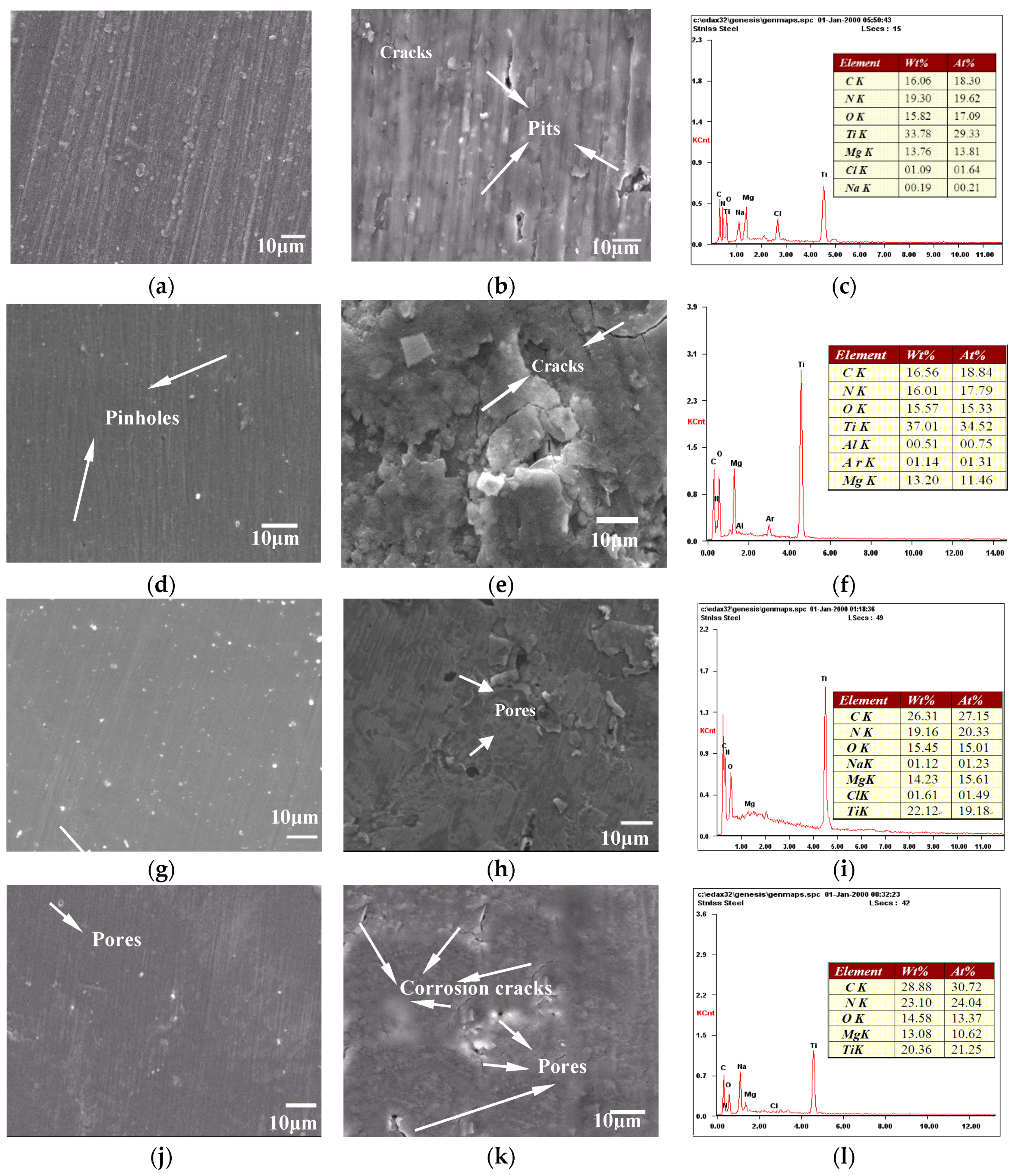
Figure 3 shows the SEM morphologies of as-deposited coatings and examined coatings by electrochemical test. It is noted that the defects like pores and pinholes are intrinsic to the physical vapor deposition (PVD) process, and this is almost impossible to completely avoid [23,24,25]. C2 is compact, but coarse with many particles; C3 is smooth but presents some tiny particles and pinholes; C5 is coarse with some tiny pores; only C4 presents flat and smooth surface with some small white spots. The defects may be produced by particle recoil of the film surface or the bombardment of charge particles, and the number and size of particles could contribute to the particles charging and the repulsive force in the plasma sheath near the substrate surface. It is clear that the C2H2 flow has great influence on surface morphology of films; the film gets smoother as the acetylene flow increases from 2 to 4 sccm. According to the authors’ inference, it is because carbon atom doping refines grains. As the acetylene flow increases to 5 sccm, the excess reaction gas may poison targets during the TiCN deposition process, which makes the sputtering process unstable and produces some granular defects and pores. Therefore, the roughness of C5 increases.
Figure 3k,l exhibits cross-sectional observations of C2 and C4 samples in order to further explore the film structure. It can be observed that the film structure is dense and compacted; C2 film shows a dense columnar structure grown perpendicular to the AZ31 surface, and C4 sample shows a smoother structure with a columnar-free feature. It is deduced that the smooth surface and columnar-free structure are caused by the formation of small size nanocrystals.
After electrochemical test, some corrosion pits, pores, and corrosion cracks are observed on the surface, but no part of the film is missing. C2 exhibits some pits, C3 presents some cracks, C4 exhibits a few pores, and C5 presents some cracks and pores. The corrosive attack is due to the columnar crystal structure and defects of the film, because chloride ions in the solution can penetrate the film through small pores or columnar crystal structure. Since TiN/TiCN coatings are more electrochemically stable than AZ31 substrate, and the exposed area begins to experience anodic dissolution with the reaction of hydrogen evolution, the corrosion compounds are formed at the same time. The structure and grain size of TiCN film were changed by the increase of C2H2 flow, such as columnar crystal to nanocrystalline, larger grains to smaller grains, and rough surface to smooth surface, which all improved the corrosion resistance and enlarged application of the substrates.
The values of the EDS analysis for samples as-deposited are given in Table 2. From EDS analysis in Figure 3c–i, the carbon content increases with the increase of FC2H2 from 2 to 5 sccm; it is the same as the as-deposited film. The oxygen is from the atmosphere after the film has undergone electrochemical corrosion. The oxygen content decreases with an increase of FC2H2, indicating the corrosion resistance was improved by carbon atoms doped. The Cl and Na elements are from NaCl solution; the Mg and Al are diffused from substrate during the electrochemical reaction. From Table 2, it can be seen that the Ti content decreases after electrochemical corrosion, and the N element has the same rules.
3.3. Corrosion Behavior
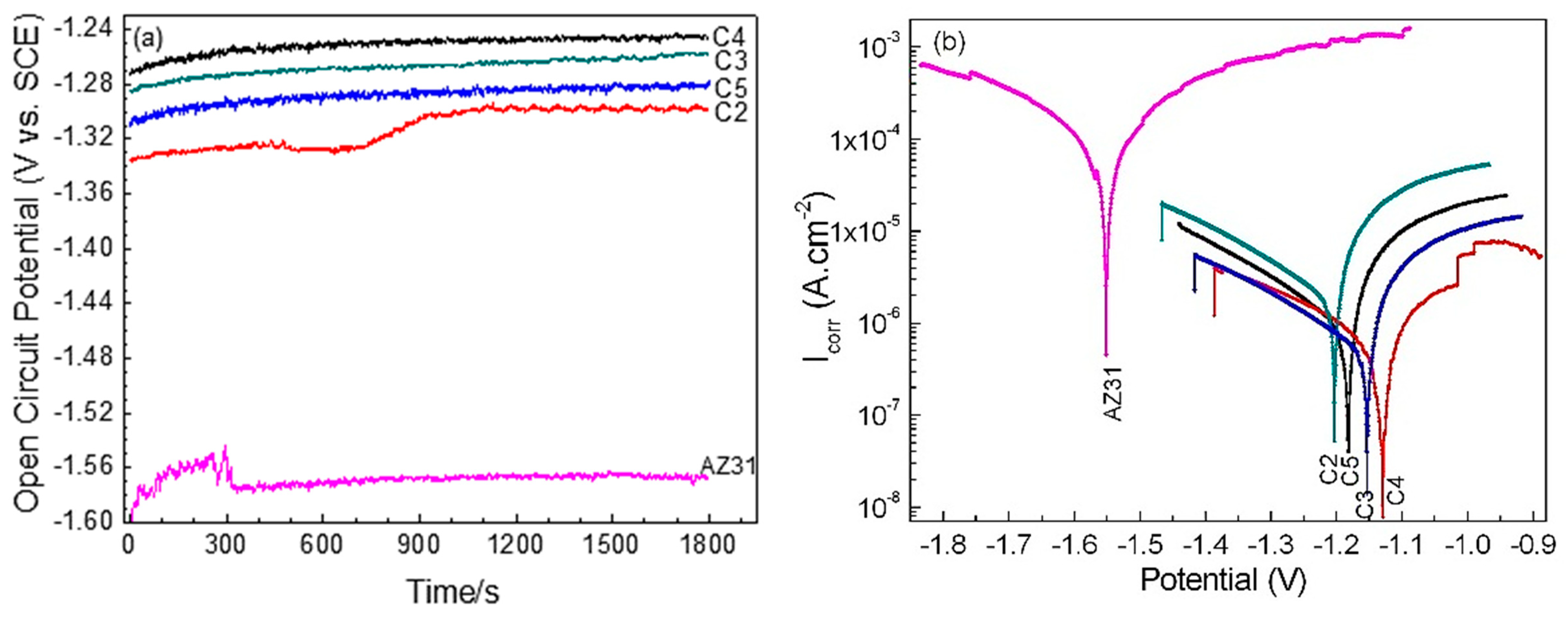
Figure 4a shows the potential-time curves, and stable octacalcium phosphates (OCPs) are obtained for all five electrodes after immersion for 1800 s. As shown in Figure 4a, the OCP of bare AZ31 in 3.5 wt % NaCl solution has the most negative potential value (−1.565 V vs. SCE), whereas the C4 has the most positive potential value (−1.245 V vs. SCE). The more positive potential indicates the less corrosion tendency of the electrode system. Figure 4b shows the potentiodynamic polarization curves of films; it is observed that the curves of the coated AZ31 shift in the direction of lower current density and nobler corrosion potential. According to the mixed potential theory [26], the films are more cathodic than AZ31. Therefore, the corrosion resistance of the coated samples is improved.
For convenience of comparison, the values of corrosion potential (Ecorr, V) and corrosion current density (Icorr, A cm−2) derived from the polarization curves by Tafel region extrapolation are shown in Table 3. The corrosion current density is related to the corrosion rate; CR (mm/day) can be obtained by using the following Equation (2) [27,28]:
According to the Equation (2), C2 presents the highest corrosion rate, but all the corrosion rates of films are greater than bare AZ31. C4 film presents the lowest rate (4.43 × 10⁻⁵ mm/day), owing to the little defects and fine grain, as well as less columnar structure, and it is much lower than other coatings, such as conversion coating in literature [29]. Among all samples, the corrosion potential of C4 increases from −1.562 to −1.129 V and the corrosion current density decreases from 8.15 × 10⁻⁴ to 7.07 × 10⁻⁷ A cm−2 due to its smooth surface, nanometer grains, and columnar crystal-free structure. It is also evident that the C2 film has poorer corrosion resistance compared with the rest films due to its greater number of defects, larger grain, and columnar structure. Comparing C4 and C5, it is found that the C5 film has poorer corrosion resistance due to its relatively rough surface and larger grains. Comparing C3 and C4, it can be inferred that SEM morphology of electrochemical test films seems very different, but corrosion rates are similar. This phenomenon can be explained as follows: the corrosion resistance of C3 is not as good as C4 film. When C3 experienced electrochemical corrosion, it could form small galvanic cells in some local defect areas and generate corrosion products. These corrosion products will accumulate in the defect area, and thus prevent the outside invasive ions from entering the internal. Therefore, the corrosion rate of C3 is similar to C4 in a short time.
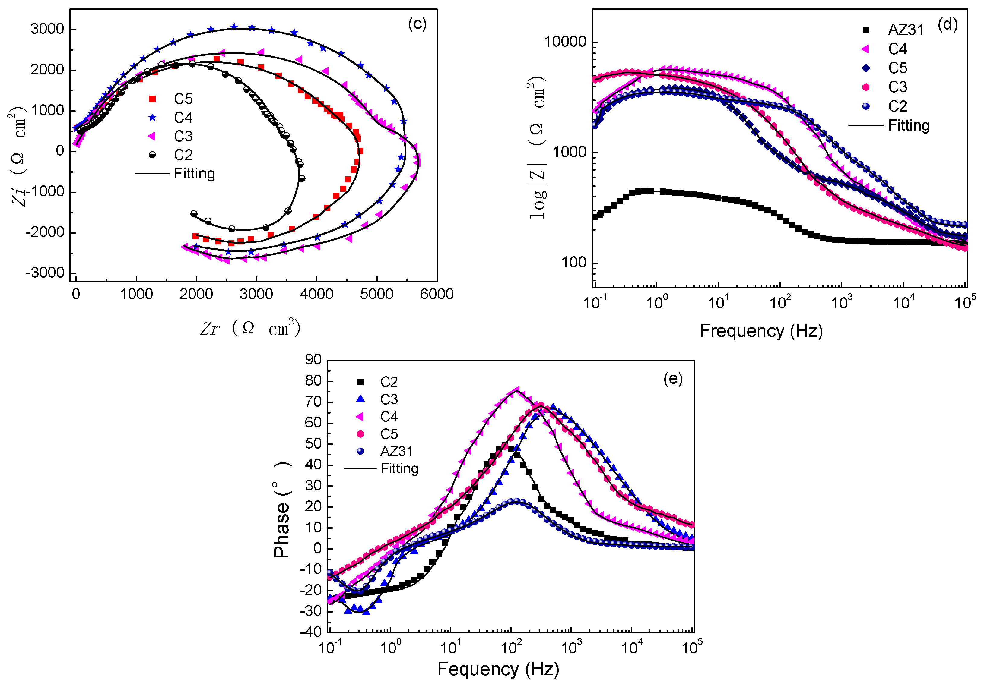
Figure 4c–e shows the results of EIS plots of the coatings. As shown in Figure 4c, the Nyquist plots are characterized by a capacitive loop in high-frequency and an inductance loop in low-frequency, and the C2 coating exhibits the smallest diameter, while the C4 coating presents the biggest one, implying that the C4 sample has a better inhibitive property. As shown in Bode plots of Figure 4d,e, the impedances of all films are higher than AZ31 immersion in the electrolyte and increase by one order compared with the bare AZ31. These indicate that the films provide an effective barrier against corrosive electrolyte ingress during EIS tests. It is clearly shown in Figure 4e that the phase angle value of the C4 sample is higher than other samples, suggesting the good barrier behavior of C4 film. However, C2 film only provides a little and limited protection effect on AZ31 due to its defects and columnar crystal structure.
Two factors can explain the enhanced corrosion resistance of coatings. First, fine grains and nanostructure were obtained, and the columnar crystal was inhibited by increasing the C2H2 flow. Second, few defects and smooth surface are other important factors to improve corrosion resistance. The two factors could reduce a direct path for the corrosive medium to pass through the film, and the corrosion path is longer than single TiCN film and blocked by the interface of a duplex structure, resulting in enhanced corrosion resistance.
4. Conclusions
In summary, the structures of TiN/TiCN composite films have been changed through alteration of C2H2 flow, and the corrosion resistance improved greatly. The smooth surface, small grain size, and equiaxial crystal structure should be explored to obtain good corrosion resistance. As is known to all, corrosion resistance of film is greatly influenced by surface defects and structure. However, surface defects are impossible to avoid completely; thus, changing the structure of film is another effective way for us to improve the corrosion resistance of coatings.
Author Contributions
H.L. wrote the paper and led the team to carry out the investigation; P.S. and Y.Z. have done the experimental details and analyzed the data; M.W. has designed the layers of coating and process parameters; Q.W. has investigated the corrosion behavior of obtained films.
Funding
This research was funded by Basic Scientific Research Operating Expenses Research Projects of Heilongjiang Provincial Institutions (No. 2017-KYYWF-0602).
Acknowledgments
The authors wish to acknowledge the Center of Metal Wear-resisting Material and Surface Engineering, Ministry of Education, for providing the some experimental conditions.
Conflicts of Interest
The authors declare no conflict of interest.
References
- Hoche, H.; Blawert, C.; Broszeit, E.; Berger, C. Galvanic corrosion properties of differently PVD-treated magnesium die cast alloy AZ91. Surf. Coat. Technol. 2005, 193, 223–229. [Google Scholar] [CrossRef]
- Paraskevas, D.; Dadbakhsh, S.; Vleugels, J.; Vanmeensel, K.; Dewulf, W.; Duflou, J.R. Solid state recycling of pure Mg and AZ31 Mg machining chips via spark plasma sintering. Mater. Des. 2016, 109, 520–529. [Google Scholar] [CrossRef]
- Li, H.; Wang, Q.; Zhuang, M.; Wu, J. Characterization and residual stress analysis of TiN/TiCN films on AZ31 magnesium alloy by PVD. Vacuum 2015, 112, 66–69. [Google Scholar] [CrossRef]
- Rashid, R.A.R.; Sun, S.; Wang, G.; Dargusch, M.S. Experimental investigation of laser assisted machining of AZ91 magnesium alloy. Int. J. Precis. Eng. Manuf. 2013, 14, 1263–1265. [Google Scholar] [CrossRef]
- Wu, G.; Zeng, X.; Ding, W.; Guo, X.; Yao, S. Characterization of ceramic PVD thin films on AZ31 magnesium alloys. Appl. Surf. Sci. 2006, 252, 7422–7429. [Google Scholar] [CrossRef]
- Ji, P.; Long, R.; Hou, L.; Wu, R.; Zhang, J.; Zhang, M. Study on hydrophobicity and wettability transition of Ni-Cu-SiC coating on Mg-Li alloy. Surf. Coat. Technol. 2018, 350, 428–435. [Google Scholar] [CrossRef]
- Apelfeld, A.; Krit, B.; Ludin, V.; Morozova, N.; Vladimirov, B.; Wu, R. The characterization of plasma electrolytic oxidation coatings on AZ41 magnesium alloy. Surf. Coat. Technol. 2017, 322, 127–133. [Google Scholar] [CrossRef]
- Li, H.; Rong, S.; Sun, P.; Wang, Q. Microstructure, Residual Stress, Corrosion and Wear Resistance of Vacuum Annealed TiCN/TiN/Ti Films Deposited on AZ31. Metals 2016, 7, 5. [Google Scholar] [CrossRef]
- Wu, G.; Zeng, X.; Yuan, G. Growth and corrosion of aluminum PVD-coating on AZ31 magnesium alloy. Mater. Lett. 2008, 62, 4325–4327. [Google Scholar]
- Altun, H.; Sen, S. The effect of DC magnetron sputtering AlN coatings on the corrosion behaviour of magnesium alloys. Surf. Coat. Technol. 2005, 197, 193–200. [Google Scholar] [CrossRef]
- Hollstein, F.; Wiedemann, R.; Scholz, J. Characteristics of PVD-coating on AZ31hp magnesium alloys. Surf. Coat. Technol. 2003, 162, 261–268. [Google Scholar] [CrossRef]
- Huo, H.; Li, Y.; Wang, F. Corrosion of AZ91D magnesium alloy with a chemical conversion coating and electroless nickel layer. Corros. Sci. 2004, 46, 1467–1477. [Google Scholar] [CrossRef]
- Wu, G.; Wang, X.; Ding, K.; Zhou, Y.; Zeng, X. Corrosion behavior of Ti-Al-N/Ti-Al duplex coating on AZ31 magnesium alloy in NaCl aqueous solution. Mater. Charact. 2009, 60, 803–807. [Google Scholar] [CrossRef]
- Altun, H.; Sen, S. The effect of PVD coatings on the wear behaviour of magnesium alloys. Mater. Charact. 2007, 58, 917–921. [Google Scholar] [CrossRef]
- Antunes, R.; Rodas, A.C.D.; Lima, N.; Higa, O.Z.; Costa, I. Costa, Study of the corrosion resistance and in vitro biocompatibility of PVD TiCN-coated AISI 316 L austenitic stainless steel for orthopedic applications. Surf. Coat. Technol. 2010, 205, 2074–2081. [Google Scholar] [CrossRef]
- Karyaoui, M.; Mhamdi, A.; Kaouach, H.; Labidi, A.; Boukhachem, A.; Boubaker, K.; Amlouk, M.; Chtourou, R. Some physical investigations on silver-doped ZnO sprayed thin films. Mater. Sci. Semicond. Proc. 2015, 30, 255–262. [Google Scholar] [CrossRef]
- Xu, L.; Xiao, S.; Zhang, C.; Zheng, G.; Su, J.; Zhao, L.; Wang, J. Optical and structural properties of Sr-doped ZnO thin films. Mater. Chem. Phys. 2014, 148, 720–726. [Google Scholar] [CrossRef]
- Yang, W.; Zhou, T.; Zhang, W.; Li, J.; Chen, Z.; Chang, F.; Zhang, H.; Zhou, H. Effect of one-step laser processed biomimetic coupling units’ degrees on rolling contact fatigue wear resistance of train track alloy steel. Surf. Coat. Technol. 2015, 277, 181–187. [Google Scholar] [CrossRef]
- Verdian, M.M.; Raeissi, K.; Salehi, M.; Sabooni, S. Characterization and corrosion behavior of NiTi-Ti2Ni-Ni3Ti multiphase intermetallics produced by vacuum sintering. Vacuum 2011, 86, 91–95. [Google Scholar] [CrossRef]
- Daroonparvar, M.; Yajid, M.A.M.; Bakhsheshi-Rad, H.R.; Yusof, N.M.; Izman, S.; Hamzah, E.; Kadir, M.R.A. Corrosion resistance investigation of nanostructured Si-and Si/TiO2-coated Mg alloy in 3.5% NaCl solution. Vacuum 2014, 108, 61–65. [Google Scholar] [CrossRef]
- Chen, R.; Tu, J.; Liu, D.; Mai, Y.; Gu, C. Microstructure, mechanical and tribological properties of TiCN nanocomposite films deposited by DC magnetron sputtering. Surf. Coat. Technol. 2011, 205, 5228–5234. [Google Scholar] [CrossRef]
- Lin, J.; Moore, J.J.; Mishra, B.; Pinkas, M.; Sproul, W.D. The structure and mechanical and tribological properties of TiBCN nanocomposite coatings. Acta Mater. 2010, 58, 1554–1564. [Google Scholar] [CrossRef]
- Korhonen, A.S. Corrosion of thin hard PVD coatings. Vacuum 1994, 45, 1031–1034. [Google Scholar] [CrossRef]
- Panjan, P.; Čekada, M.; Panjan, M.; Kek-Merl, D. Growth defects in PVD hard coatings. Vacuum 2009, 84, 209–214. [Google Scholar] [CrossRef]
- Wu, G.; Dai, W.; Zheng, H.; Wang, A. Improving wear resistance and corrosion resistance of AZ31 magnesium alloy by DLC/AlN/Al coating. Surf. Coat. Technol. 2010, 205, 2067–2073. [Google Scholar] [CrossRef]
- Shi, P.; Niu, B.; Shanshan, E.; Chen, Y.; Li, Q. Preparation and characterization of PLA coating and PLA/MAO composite coatings on AZ31 magnesium alloy for improvement of corrosion resistance. Surf. Coat. Technol. 2015, 262, 26–32. [Google Scholar] [CrossRef]
- Shi, Z.; Atrens, A. An innovative specimen configuration for the study of Mg corrosion. Corros. Sci. 2011, 53, 226–246. [Google Scholar] [CrossRef]
- Bakhsheshi-Rad, H.; Hamzah, E.; Daroonparvar, M.; Saud, S.N.; Abdul-Kadir, M.R. Bi-layer nano-TiO2/FHA composite coatings on Mg-Zn-Ce alloy prepared by combined physical vapour deposition and electrochemical deposition methods. Vacuum 2014, 110, 127–135. [Google Scholar] [CrossRef]
- Gu, C.; Yan, W.; Zhang, J.; Tu, J. Corrosion resistance of AZ31B magnesium alloy with a conversion coating produced from a choline chloride-Urea based deep eutectic solvent. Corros. Sci. 2016, 106, 108–116. [Google Scholar] [CrossRef]
Figure 1.
XRD patterns of all samples (a) as-deposited films; (b) electrochemical test films.

Figure 2.
High-resolution transmission electron microscopy (HRTEM) image observation of (a) C4 and (b) C5.
Figure 2.
High-resolution transmission electron microscopy (HRTEM) image observation of (a) C4 and (b) C5.
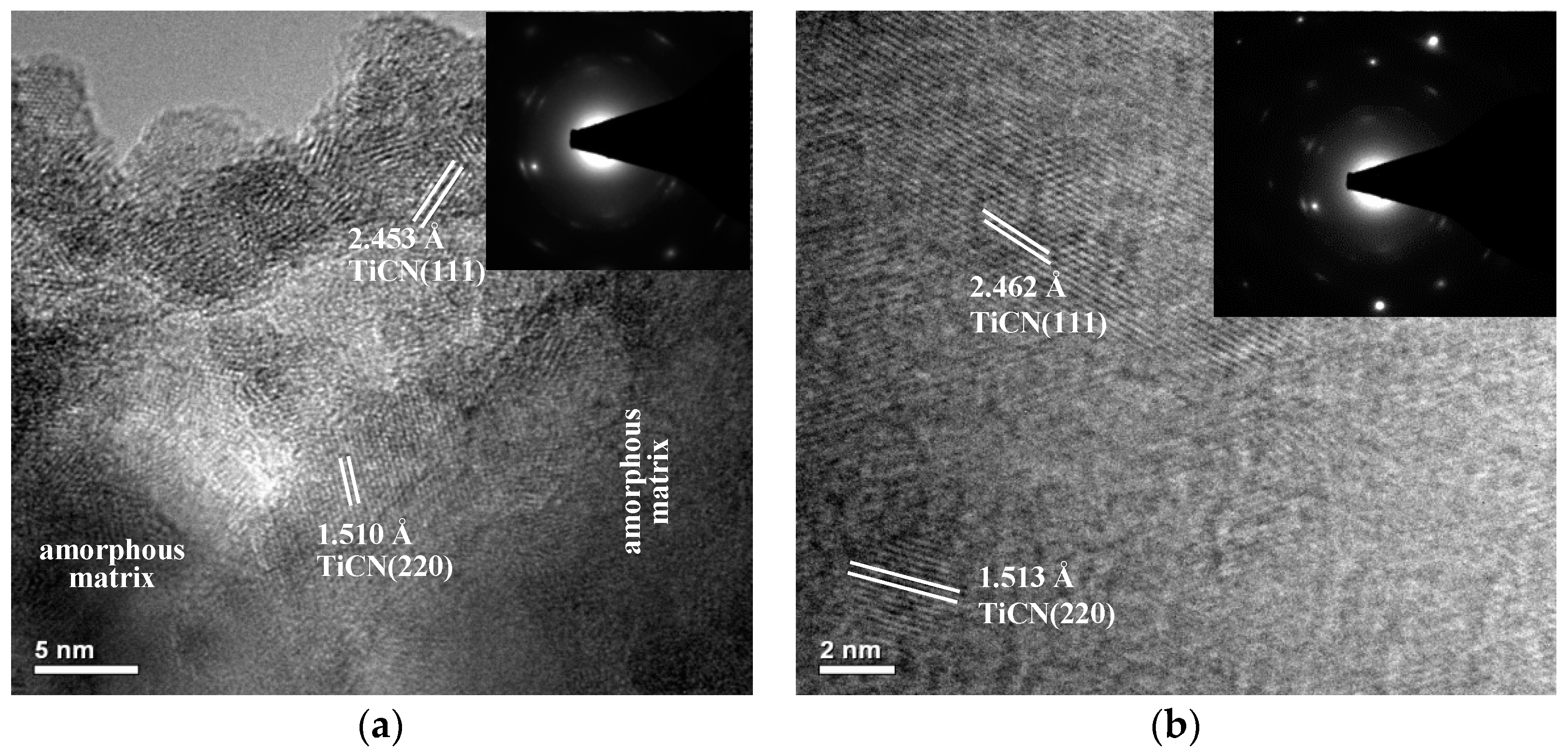
Figure 3.
SEM morphology of as-deposited films, electrochemical test films, and EDS analysis after electrochemical test: (a–c) C2, (d–f) C3, (g–i) C4, (j–l) C5, (m) and (n) cross-section of deposited film of sample C2 and C4; (o) cross-section of electrochemical test film of sample C2. The films fabricated with 2, 3, 4, and 5 sccm were presented as samples C2, C3, C4, and C5, respectively.

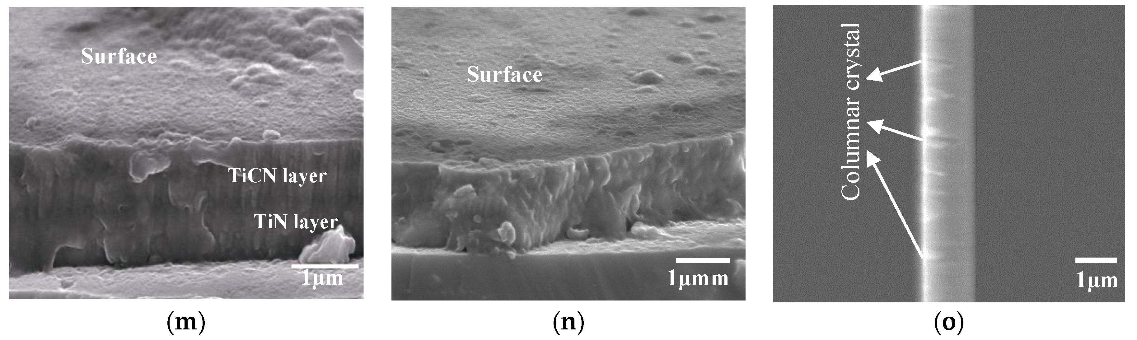
Figure 4.
(a) Open circuit potential curves of the bare AZ31 and films as a function of time; (b) Potentiodynamic polarization curves of the bare AZ31 and films; (c) Nyquist plots; (d) Bode plots of log |Z| vs. frequency; (e) Bode phase angle plots.
Figure 4.
(a) Open circuit potential curves of the bare AZ31 and films as a function of time; (b) Potentiodynamic polarization curves of the bare AZ31 and films; (c) Nyquist plots; (d) Bode plots of log |Z| vs. frequency; (e) Bode phase angle plots.


Table 1.
The grain size values of coatings (nm).
| Coatings | Grain Size (nm) |
|---|---|
| C2 | 33.67 |
| C3 | 30.03 |
| C4 | 25.51 |
| C5 | 25.95 |
Table 2.
The values of the energy dispersive X-ray spectroscopy (EDS) analysis for samples as-deposited (wt %).
Table 2.
The values of the energy dispersive X-ray spectroscopy (EDS) analysis for samples as-deposited (wt %).
| Samples | Ti | C | N |
|---|---|---|---|
| C2 | 49.13 | 18.55 | 32.32 |
| C3 | 46.26 | 22.99 | 30.75 |
| C4 | 44.97 | 25.89 | 29.14 |
| C5 | 42.08 | 28.74 | 29.18 |
Table 3.
Electrochemical data of substrate and films obtained from potentiodynamic polarization curves.
Table 3.
Electrochemical data of substrate and films obtained from potentiodynamic polarization curves.
| Samples | Corrosion Potential Ecorr (V) | Current Density Icorr (A cm−2) | Corrosion Rate CR (mm/day) |
|---|---|---|---|
| Uncoated AZ31 | −1.562 | 8.15 × 10⁻⁴ | 5.1 × 10⁻² |
| C2 | −1.188 | 4.78 × 10⁻⁶ | 2.99 × 10⁻⁴ |
| C3 | −1.151 | 7.65 × 10⁻⁷ | 4.79 × 10⁻⁵ |
| C4 | −1.129 | 7.07 × 10⁻⁷ | 4.43 × 10⁻⁵ |
| C5 | −1.173 | 1.05 × 10⁻⁶ | 6.57 × 10⁻⁵ |
© 2018 by the authors. Licensee MDPI, Basel, Switzerland. This article is an open access article distributed under the terms and conditions of the Creative Commons Attribution (CC BY) license (http://creativecommons.org/licenses/by/4.0/).
Share and Cite
MDPI and ACS Style
Li, H.; Sun, P.; Zhu, Y.; Wu, M.; Wang, Q. Influence of C2H2 Flows on Microstructure and Corrosion Resistance of TiCN Films Doped with Carbon Atoms. Coatings 2018, 8, 458. https://doi.org/10.3390/coatings8120458
AMA Style
Li H, Sun P, Zhu Y, Wu M, Wang Q. Influence of C2H2 Flows on Microstructure and Corrosion Resistance of TiCN Films Doped with Carbon Atoms. Coatings. 2018; 8(12):458. https://doi.org/10.3390/coatings8120458
Chicago/Turabian StyleLi, Haitao, Pengfei Sun, Yongchang Zhu, Mingzhong Wu, and Qiang Wang. 2018. "Influence of C2H2 Flows on Microstructure and Corrosion Resistance of TiCN Films Doped with Carbon Atoms" Coatings 8, no. 12: 458. https://doi.org/10.3390/coatings8120458
Note that from the first issue of 2016, this journal uses article numbers instead of page numbers. See further details here.