Article

Scan-Mode Atmospheric-Pressure Plasma Jet Processed Reduced Graphene Oxides for Quasi-Solid-State Gel-Electrolyte Supercapacitors

1
Department of Electrical Engineering, National Taiwan University, Taipei City 10617, Taiwan
2
Graduate Institute of Applied Mechanics, National Taiwan University, Taipei City 10617, Taiwan
3
Department of Chemical Engineering, National Taiwan University, Taipei City 10617, Taiwan
4
Graduate Institute of Photonics and Optoelectronics, National Taiwan University, Taipei City 10617, Taiwan
*
Author to whom correspondence should be addressed.
Coatings 2018, 8(2), 52; https://doi.org/10.3390/coatings8020052
Submission received: 18 December 2017 / Revised: 22 January 2018 / Accepted: 26 January 2018 / Published: 29 January 2018
(This article belongs to the Special Issue Nanostructured Thin Films)

Abstract

:
A scanning atmospheric-pressure plasma jet (APPJ) is essential for high-throughput large-area and roll-to-roll processes. In this study, we evaluate scan-mode APPJ for processing reduced graphene oxides (rGOs) that are used as the electrodes of quasi-solid-state gel-electrolyte supercapacitors. rGO nanoflakes are mixed with ethyl cellulose (EC) and terpineol to form pastes for screen-printing. After screen-printing the pastes on carbon cloth, a DC-pulse nitrogen APPJ is used to process the pastes in the scan mode. The maximal temperature attained is ~550 °C with a thermal influence duration of ~10 s per scan. The pastes are scanned by APPJ for 0, 1, 3 and 5 times. X-ray photoelectron spectroscopy (XPS) indicates the reduction of C-O binding content as the number of scan increases, suggesting the oxidation/decomposition of EC. The areal capacitance increases and then decreases as the number of scan increases; the best achieved areal capacitance is 15.93 mF/cm2 with one APPJ scan, in comparison to 4.38 mF/cm2 without APPJ processing. The capacitance retention rate of the supercapacitor with the best performance is ~93% after a 1000-cycle cyclic voltammetry (CV) test. The optimal number of APPJ scans should enable the proper removal of inactive EC and improved wettability while minimizing the damage caused to rGOs by nitrogen APPJ processing.

Graphical Abstract

1. Introduction

Atmospheric-pressure plasma (APP) is a technology that can be operated at regular pressure without using vacuum pumps and a vacuum chamber; therefore, it is considered a cost-effective technology [1,2,3,4]. Several techniques have been developed to overcome problems such as high breakdown voltage, continuous arcing and instability, making APPs ready for industrial applications [5,6]. These techniques include the use of pointed electrodes (corona discharges), application of a dielectric material to cover at least one of the electrodes (dielectric barrier discharge, DBD), applications of miniaturized plasma to enlarge the surface-to-volume ratio for enhanced heat dissipation (microplasma), use of high-speed flows for efficient convective heat dissipation (atmospheric-pressure plasma jet, APPJ) and discharge pulsing and AC signal excitation of plasma [4]. Usually, one or several of these techniques combined is used for generating and stabilizing APPs. Coplanar DBD is frequently used for large-area roll-to-roll process at relatively low gas temperature [7]. When APPJ is used for large-area processing, multiple jets with a scanning stage are typically essential for high-throughput large-area roll-to-roll processes.
Various excitation methods for APPs lead to various combinations of electron density and gas temperature. The feature of generating reactive free radical species and UV radiation at biotolerable temperatures has attracted interest for biomedical applications such as sterilization, bacteria inactivation and cancer treatment [3,8,9,10,11]. Some APPs possess slightly higher electron density and moderate gas temperature of the order of hundreds of degrees Celsius. In such APPs, the synergetic effects of reactive species and heat trigger high plasma-chemical reactivity, thus affording ultrafast materials processing capability [12,13,14,15,16,17,18,19,20]. For example, a DC-pulse nitrogen APPJ shows high reactivity with carbonaceous materials and the processing times for carbon nanotubes (CNTs) and reduced graphene oxides (rGOs) are within 30 s [12,15,18,19,20,21,22]. Carbon-based materials react violently with the reactive species of nitrogen plasma at the APPJ self-sustained temperature, as evidenced by optical emission spectroscopy (OES) observations of CN-emission systems. A microplasma jet has been used for patterning a CNT layer [23]; in this case, ozone generated by the microplasma jet is considered the major oxidation reactant. Reactive oxygen atoms in APPJ are considered the main etchant for polyimide [24,25]. Other applications in food processing and agriculture [26,27,28] and surface modification with adhesion enhancement [29] also show high potential [29,30,31,32].
Supercapacitors are high-power-density energy-storage devices that can be operated under a fast charging-discharging condition [33,34]. Two typical mechanisms are involved in charge storage: pseudocapacitance and electrical double-layer capacitance (EDLC). Pseudocapacitance arises from Faradaic reaction of electrode surface materials such as metal oxides and conductive polymers [35,36]. EDLC involves ion adsorption at the electrolyte-electrode interface; this typically occurs in carbon-based materials such as activated carbon black, CNTs and graphenes [18,19,20,37,38,39]. Since Geim et al. [40] separated graphite into graphene in 2004, the properties of graphene has been investigated extensively. Many applications are designed based on graphene’s outstanding properties such as high mechanical strength, high thermal conductivity and excellent electrical conductivity. Graphene has been applied in various fields such as solar cells [21], fuel cells [41], supercapacitors [18,19] and electrochemical sensors [42]. Supercapacitors with high areal capacitance also have been realized using hierarchical carbon tubular nanostructures [43]. Composite materials consisting of materials with pseudocapacitance and EDLC have also been extensively investigated [33,44]. Microplasma jet etching has been used for defining patterns on coplanar CNT micro-supercapacitors without masks [23]. Scanning atmospheric-pressure glow discharge plasma has been proposed as an eco-friendly and cost-effective strategy for the instantaneous (within 2 s) reduction of graphene oxide (GO) paper for supercapacitor application [45]. Stationary DC-pulse nitrogen APPJs have been used for preparing CNT and rGO electrodes for supercapacitors with processing time within 30 s [18,19,20]. Corona negative glow has been applied for the instantaneous reduction of GO paper [45]; scanning atmospheric plasma also has been used for ultrafast reduction of GO and fabrication of highly conductive graphene films and patterns [46]. Because the APPJ zone of influence is localized, multiple jets with a scanning stage are required for high-throughput large-area processing. In this study, we experimentally investigate rGO supercapacitors fabricated by using a scan-mode DC-pulse nitrogen APPJ. The results of this study confirm the feasibility of one scan APPJ process for supercapacitor fabrication. This opens up an opportunity for applying this technology to continuous roll-to-roll processes with higher temperature tolerant flexible substrates such as stainless steel, carbon cloth and willow glass.

2. Materials and Methods

2.1. rGO Pastes Preparation

0.1 g of rGO nanoflakes (purity 99%, thickness: <5 nm, sheet diameter: 0.1‒5 µm, Golden Innovation Business Co., Ltd., New Taipei City, Taiwan), 0.245 g of terpineol (anhydrous, #86480, Fluka, St. Louis, MO, USA), 0.4698 g of ethanol, 1.4 g of 10 wt % ethyl cellulose (EC) (5–15 mPa·s, #46070, Fluka) ethanolic solution, 1.8 g of 10 wt % EC (30–50 mPa·s, #46080, Fluka) ethanolic solution were mixed and stirred at 450 rpm for one day using a magnetic stirrer (PC-420D, Corning Inc., Corning, NY, USA), following which 4 mL of the mixture was extracted and concentrated at 55 °C for 5 min by using a rotovap (N-1200AVF, Taipei City, Taiwan).

2.2. Supercapacitor Fabrication

rGO pastes were deposited onto carbon cloth with a feature dimension of 1.5 cm × 2 cm by screen-printing. Next, a DC-pulse nitrogen APPJ (Industrial Technology Research Institute, Hsinchu County, Taiwan) was used to sinter the printed rGO pastes with a stage scan rate of 0.75 cm/s. Samples were sintered by APPJ for 0/1/3/5 scan times. Figure 1 shows a schematic of the DC-pulse APPJ setup with a motorized scanning stage. The APPJ operation parameters were 30 slm (standard liter per minute) of nitrogen gas flow, operation voltage of 275 V, pulse duration of 7 µs and repetition rate of 25 kHz. The applied voltage was increased to >10 kV by using a transformer. A quartz tube with a length of 2.7 cm and inner diameter of 3 cm was installed downstream of the APPJ to reduce the quenching effect of ambient air. This arrangement of the quartz tube can extend and expand the plasma plume with an increased plasma influencing zone [47]. The detailed characterization of this DC-pulse APPJ has been described elsewhere [47,48,49,50]. At each pulse power period, the plasma undergoes a glow-to-arc transition. The main factors influencing the characteristics of this transition are the gas flow rate, applied voltage and duty cycle. The plasma reactivity is controlled by the power input to the plasma as well as the decay process of the reactive species upon formation. The reactivity increases with an increase in the applied voltage and the gas flow rate; the jet temperature increases with an increase in the applied voltage and with a decrease in the flow rate. Figure 1b shows the evolution of the substrate temperature during five APPJ scans. The APPJ influencing duration was ~10 s per scan. The maximal temperature attained was ~500–550 °C. The substrate temperature was measured using a K-type thermocouple (National Instrument, Austin, TX, USA) attached to the substrate and was recorded on a computer. The rGO pastes containing ethyl cellulose as binders. According to thermogravimetric analysis (TGA), the ethyl cellulose decomposes at ~312 °C [51]. DC-pulse nitrogen APPJ with plasma-heated substrate temperature of ~500–550 °C can ensure the rapid burnout of the organic binders. Figure 1c shows the image of scan-mode nitrogen APPJ during operation.
After APPJ processing, the carbon cloth with screen-printed rGOs was attached to polyethylene terephthalate (PET) substrate. A gel electrolyte was prepared by mixing 15 mL 1-M H2SO4 aqueous solution with 1.5 g of PVA and stirring at 80 °C for 4 h by using a magnetic stirrer. A polyvinyl alcohol (PVA) and H2SO4 blended gel was spread onto the rGO-coated carbon cloth and dried naturally. This coating procedure was repeated three times. Finally, two separate gel-coated electrodes were pressed together on the gel-sides to form a sandwich-structure supercapacitor.

2.3. Characterization of rGO-Coated Carboncloth and Supercapacitors

The optical emissions from the plasma during APPJ processing were monitored using a spectrometer (USB4000, Ocean Optics, Largo, FL, USA). The APPJ-sintered rGOs on carbon cloth were examined by scanning electron microscopy (SEM, JSM-7800F Prime, JEOL, Tokyo, Japan) and X-ray photoelectron spectroscopy (XPS, Thermo K-Alpha, VGS, Waltham, MA, USA) with Al Kα source. XPSPEAK 4.1 software was used for the analyses of binding energy spectra. The water contact angle was measured using a goniometer (Model 100SB, Sindetake, Taipei City, Taiwan) with a droplet volume of 3.5 µL. Cyclic voltammetry (CV), galvanostatic charging-discharging (GCD) and CV cycling stability tests were performed using an electrochemical workstation (Zahner Zennium, Kronach, Germany).

3. Results and Discussion

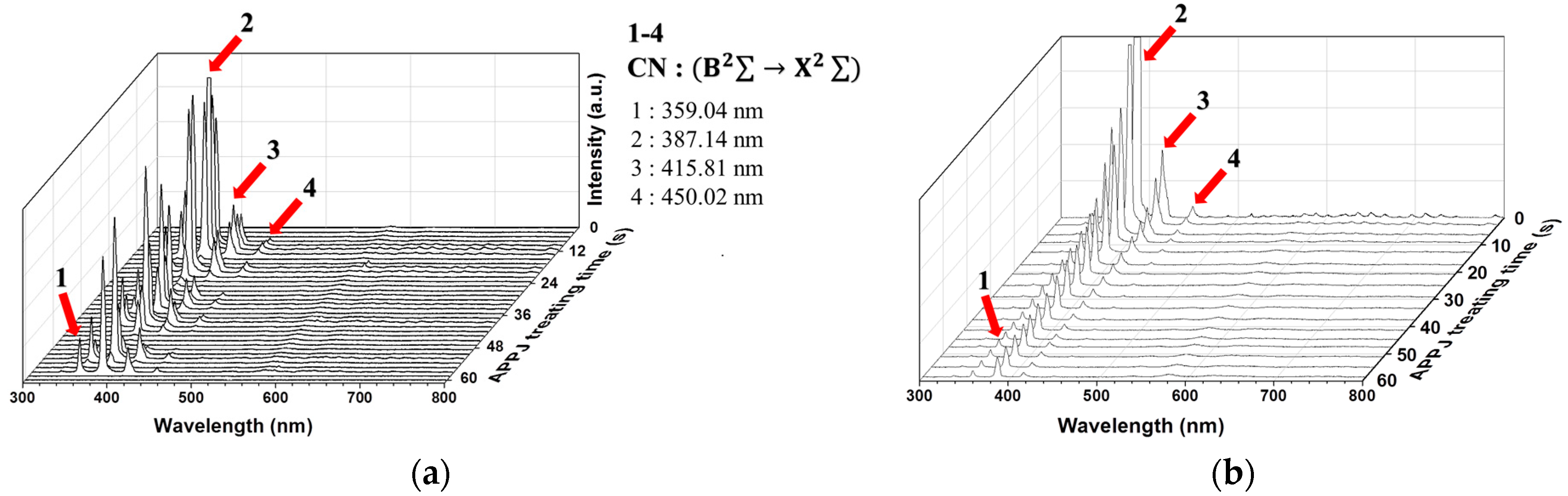
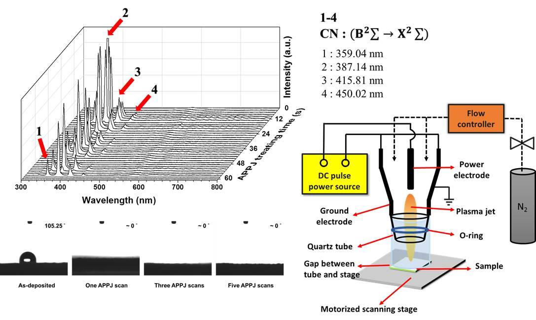
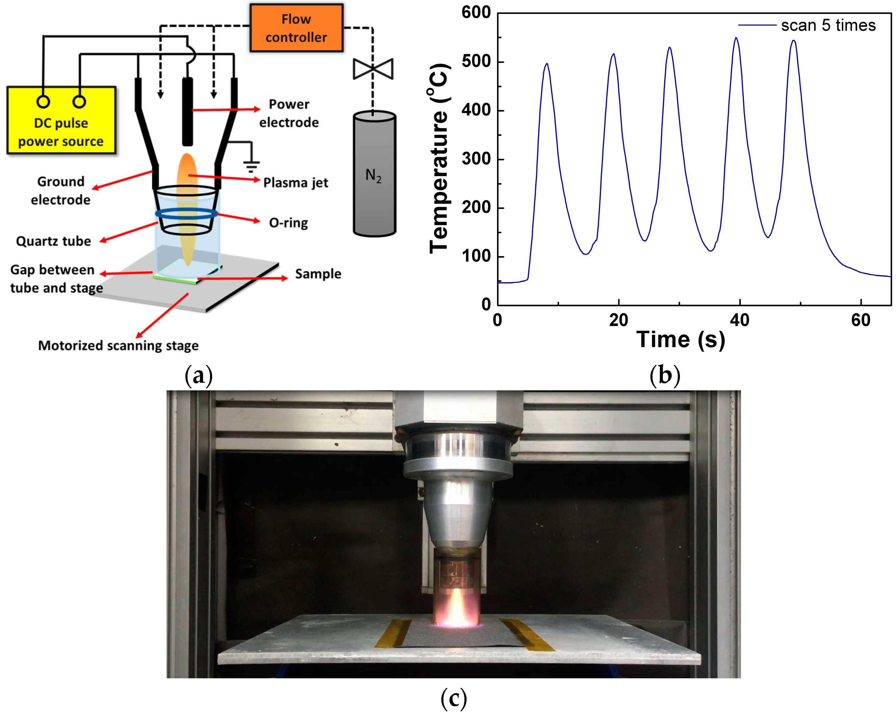
3.1. OES of Plasma during APPJ Processing

Figure 2a shows the OES of plasma during scan-mode APPJ processing. CN emissions can be clearly observed as the APPJ is scanned over the screen-printed pastes, suggesting the reaction between reactive nitrogen species in plasma and carbon-based materials. As the number of APPJ scans increases, the CN emission intensity decreases, indicating the decreased amount of carbonaceous materials. Reactive nitrogen plasma species react violently with both EC and rGOs. This reaction is even more vigorous with EC than with rGOs [12,22], as evidenced by XPS results shown later. The gaseous reactants containing –CN bonds underwent excitation-relaxation processes to emit intense CN violet emissions. Figure 2b shows the OES of plasma during the stationary APPJ processing of the rGO pastes on carbon cloth. The CN emission intensity clearly decreased as the APPJ processing time increased. These results are consistent with previous results of APPJ processing of rGOs pastes on a fluorine-doped tin oxide substrate [12,21,22], except that the residual CN emission intensity is stronger in the present study. This is because the carbon cloth contains carbon fibers and some reaction between reactive nitrogen plasma species and the carbon fibers still occurred after rGO and EC were consumed. Nitrogen plasmas have high reactivity [52] because of excited nitrogen molecules (N2 1st positive (B3Пg→A3+u) and N2 2nd positive (C3Пu→B3Пg; the intensities of these two transitions are small compared with those of CN emission system) [48]. These excited state molecules possess energy over 6 eV above the ground state. Upon collision with the treated materials, the quenching of these molecules provides extra energy. The existence of excited nitrogen molecules together with the high jet temperature make the ultra-short processing time possible.

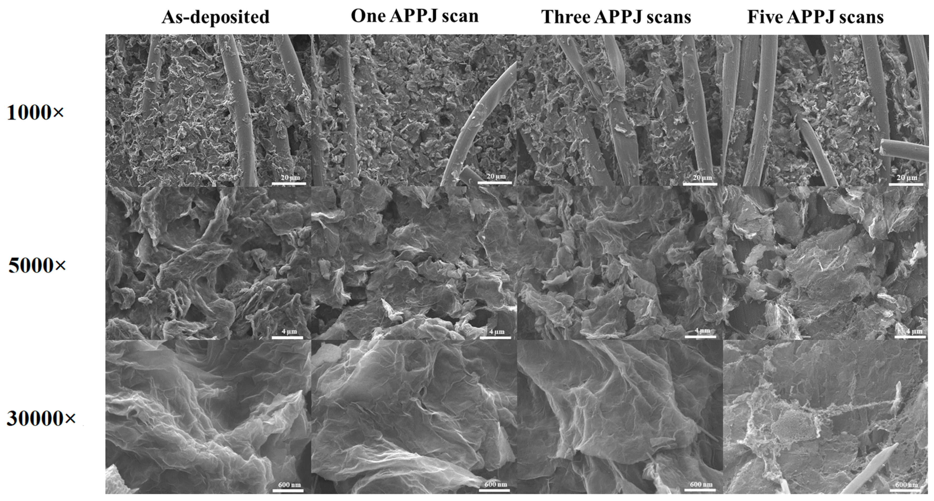
3.2. SEM Images of APPJ-Processed rGOs on Carbon Cloth

Figure 3 shows SEM images of the APPJ-processed rGOs on carbon cloth. In images with 1000× magnification, carbon fibers can be clearly observed with screen-printed rGOs filled in the spaces between fibers. This increases the overall surface area of the electrode used for a supercapacitor. In samples processed with five APPJ scans, some fibers clearly broke owing to the reaction of the nitrogen APPJ at the self-sustained plasma temperature. Images with 5000× and 30,000× magnifications show that the screen-printed rGOs are flake-like after APPJ processing. In samples processed with five APPJ scans, some nano-holes can clearly be seen in the rGO flakes in the image with 30,000× magnification. This indicates that the nitrogen APPJ reacts with and damages the rGOs. This may result in deteriorated supercapacitor performance as the APPJ scan time increases, as shown later in this paper.

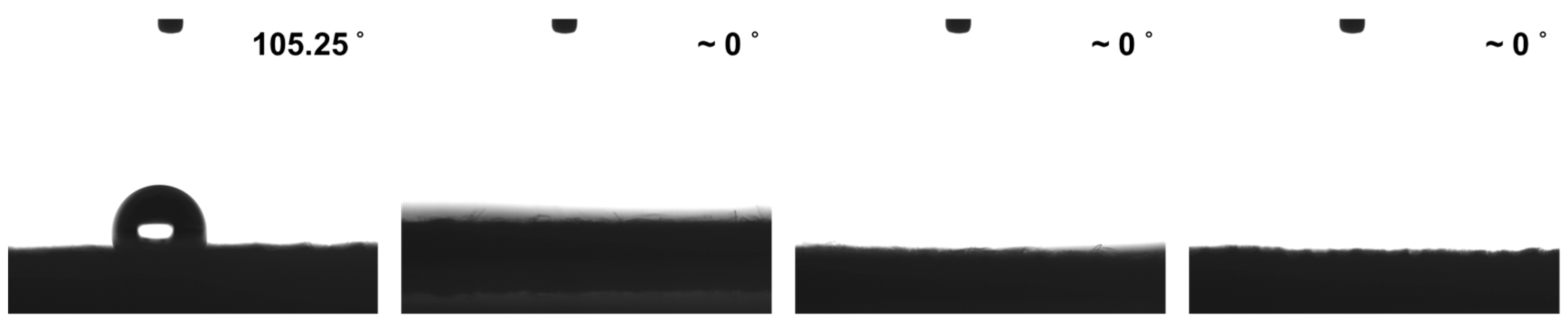
3.3. Water Contact Angle Measurement of APPJ-Processed rGOs on Carbon Cloth

Figure 4 shows the water contact angle measurement results of the APPJ-processed rGOs on carbon cloth. The as-deposited rGOs showed high water contact angle of ~105°. After one APPJ scan, the rGOs on carbon cloth became highly hydrophilic and the water droplet completely penetrated the nanopores by capillary force. The exact contact angle is therefore unable to determine for APPJ-processed rGOs on carbon cloth. This could be attributed to the introduction of hydrophilic surface functional groups –OH and –COOH by the nitrogen APPJ. The nitrogen doping can also improve the hydrophilicity of the carbon-based materials [53]. This is evidenced by the XPS results as discussed below. Improved wettability could enhance the contact between the electrolyte and the electrode, thereby enhancing the supercapacitor performance.

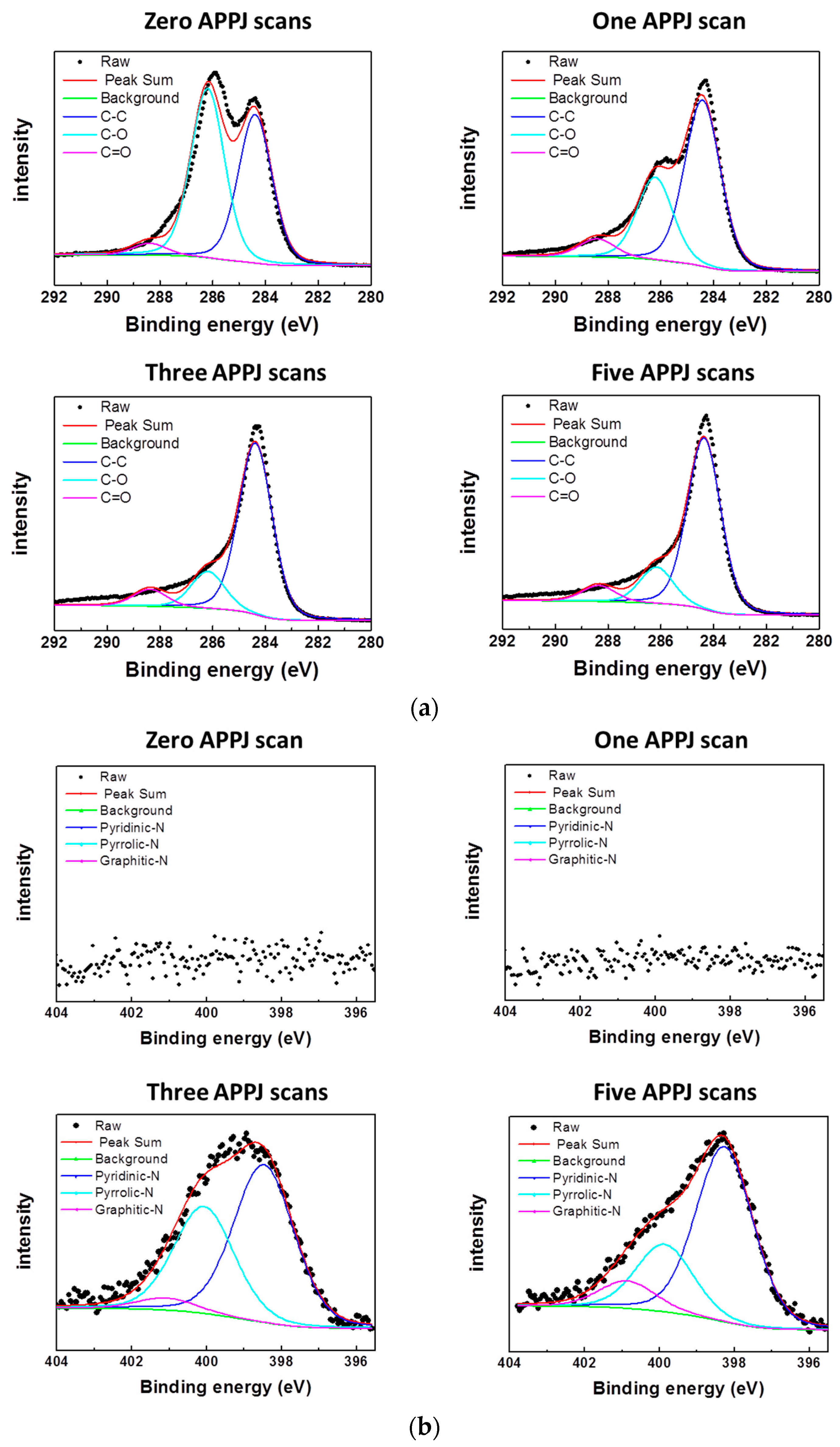
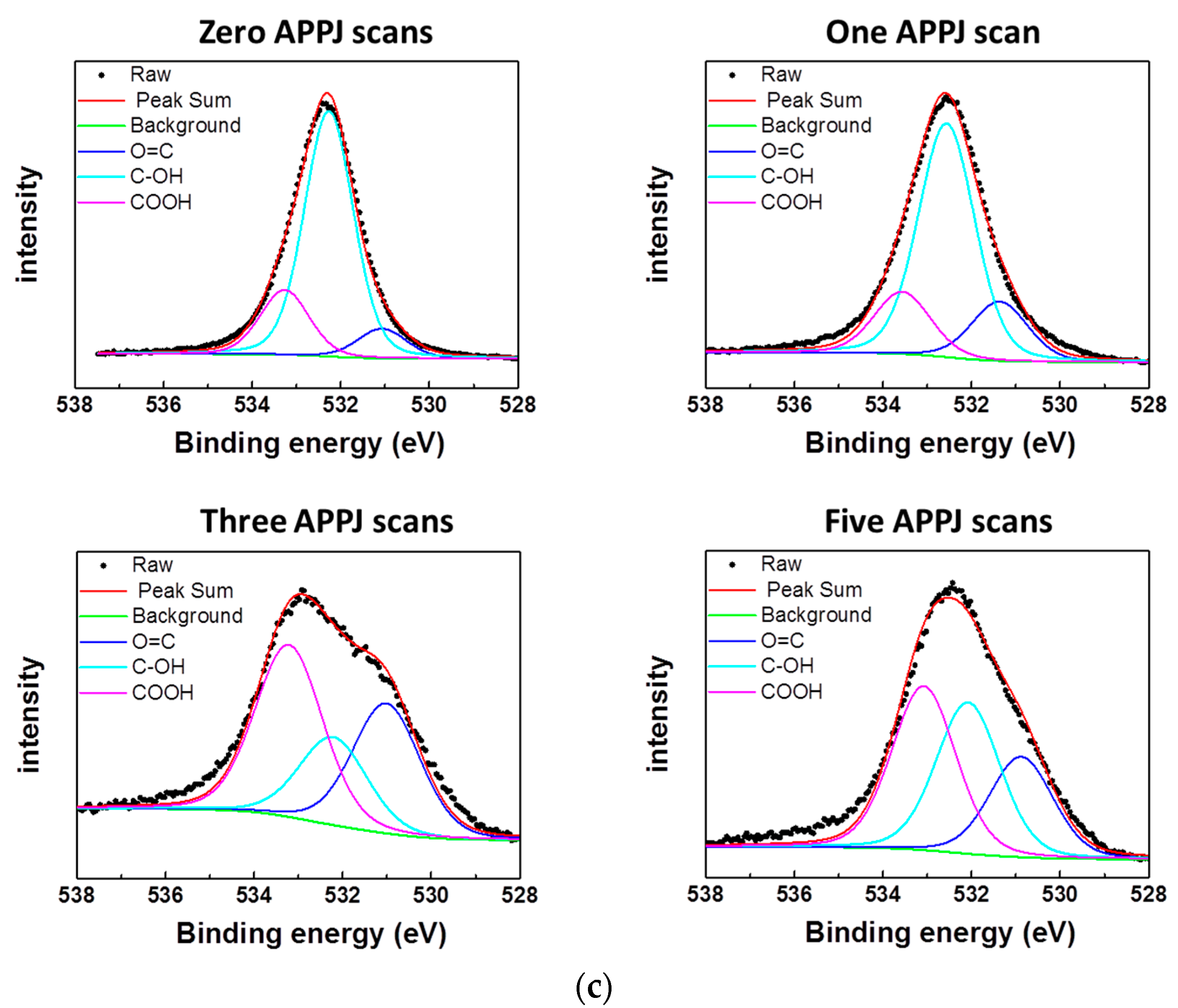
3.4. XPS Results of APPJ-Processed rGOs on Carbon Cloth

Figure 5 shows the XPS spectra of C 1s, N 1s and O 1s. Table 1 lists the bonding content ratios. Figure 5a shows the C 1s XPS spectra with deconvoluted peaks located at 284.5 eV (C–C), 286.3 eV (C–O) and 288.5 eV (C=O) [54]. The C–C content is mainly contributed by rGOs and the carbon fibers of the carbon cloth and the C–O content, by EC. The sample with zero APPJ scans showed high C–O content of 51.40%, which decreased to 31.30% after one APPJ scan. After 5 APPJ scans, the C–O content was further reduced to 18.64%. This indicates that EC decomposes rapidly and reacts violently with the reactive nitrogen plasma species at the APPJ self-sustained temperature. The removal of EC can create a nanoporous structure that facilitates the contact between the electrolyte and the rGO electrodes. Figure 5b shows the N 1s XPS spectra with deconvoluted peaks located at 398.3 eV (pyridinic-N), 399.9 eV (pyrrolic-N) and 400.9 eV (graphitic-N) [55]. No nitrogen signal was detected for samples with zero and one APPJ scans. The nitrogen signal started to appear after three APPJ scans, indicating nitrogen doping into rGOs and/or carbon fibers. Nitrogen doping in carbonaceous materials is considered to benefit the supercapacitor performance [55]. Our APPJ processes can create holes on rGOs [12,18,19,21,22,56]. Nitrogen-doped rGOs with holes have been demonstrated enhanced supercapacitor performance [53,57]. Samples with three APPJ scans showed the content of pyridinic-N content of 54.18%; after 5 scans, this increased to 62.62%. This observation agrees with theoretical calculations which suggest that N-doped graphene with pyridinic-like holes is more thermodynamically stable [57]. However, the enhancement of supercapacitive behavior by nitrogen-doped graphenes is not observed in our CV results (as discussed later in Section 3.6). Redox peaks associated with the pseudocapacitance of nitrogen doped graphenes are not shown in our CV results even at the lowest potential scan rate of 2 mV/s. In addition, nitrogen doping occurs in samples after three and five APPJ scans; however, the sample with one APPJ scan shows the best capacitance. This discrepancy may be attributed to the fact that our experimental and sample conditions may quite differ from the assumptions made based on the theoretical calculations. Figure 5c shows the O 1s spectra with deconvoluted peaks located at 531.1 eV (O=C), 532.3 eV (C–OH) and 533.3 eV (–COOH) [55]. After three APPJ scans, the O 1s spectrum shows a clear shape change with increased O=C content. With a further increase in the number of APPJ scans, the O=C content decreased. Overall, the O=C content increased and then decreased as the number of APPJ scans increased. This trend is consistent with the data analyzed from the C 1s spectra.

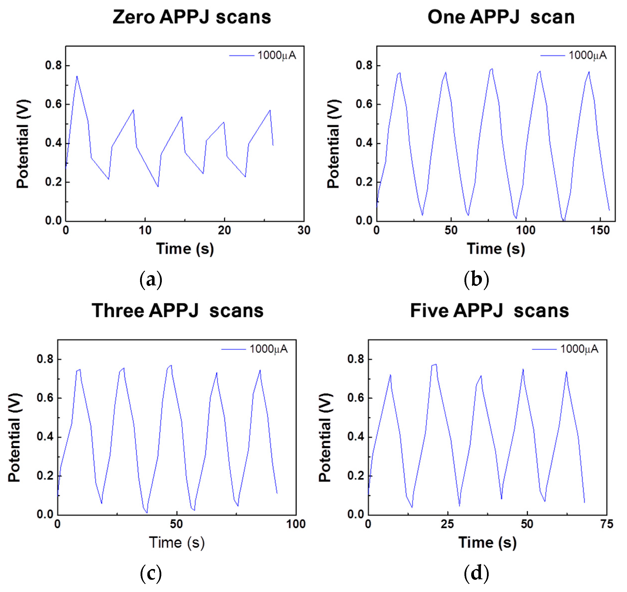
3.5. GCD Results of Gel-Electrolyte Supercapacitor

The real capacitance can be calculated from the GCD results based on the following equation [20].
C areal = I Δ t A Δ V
where ΔV is the voltage window; I, the constant current during GCD operation; Δt, the discharging time; and A, the apparent area of the electrode.
Figure 6 shows the GCD results of rGO-coated carbon cloth supercapacitors under various numbers of APPJ scans. Without APPJ treatment, the charging-discharging curve is highly irregular, possibly owing to the existence of too much inactive EC in the electrode. After APPJ processing, the charging-discharging curve became much smoother and showed a triangular shape, indicating rapid charging-discharging. At a constant current of 1000 µA, the areal capacitance values are 6.95, 4.32 and 3.31 mF/cm2 for supercapacitors with one, three and five APPJ scans, respectively. Without APPJ processing (zero scans), the curve is too irregular to calculate the capacitance value.

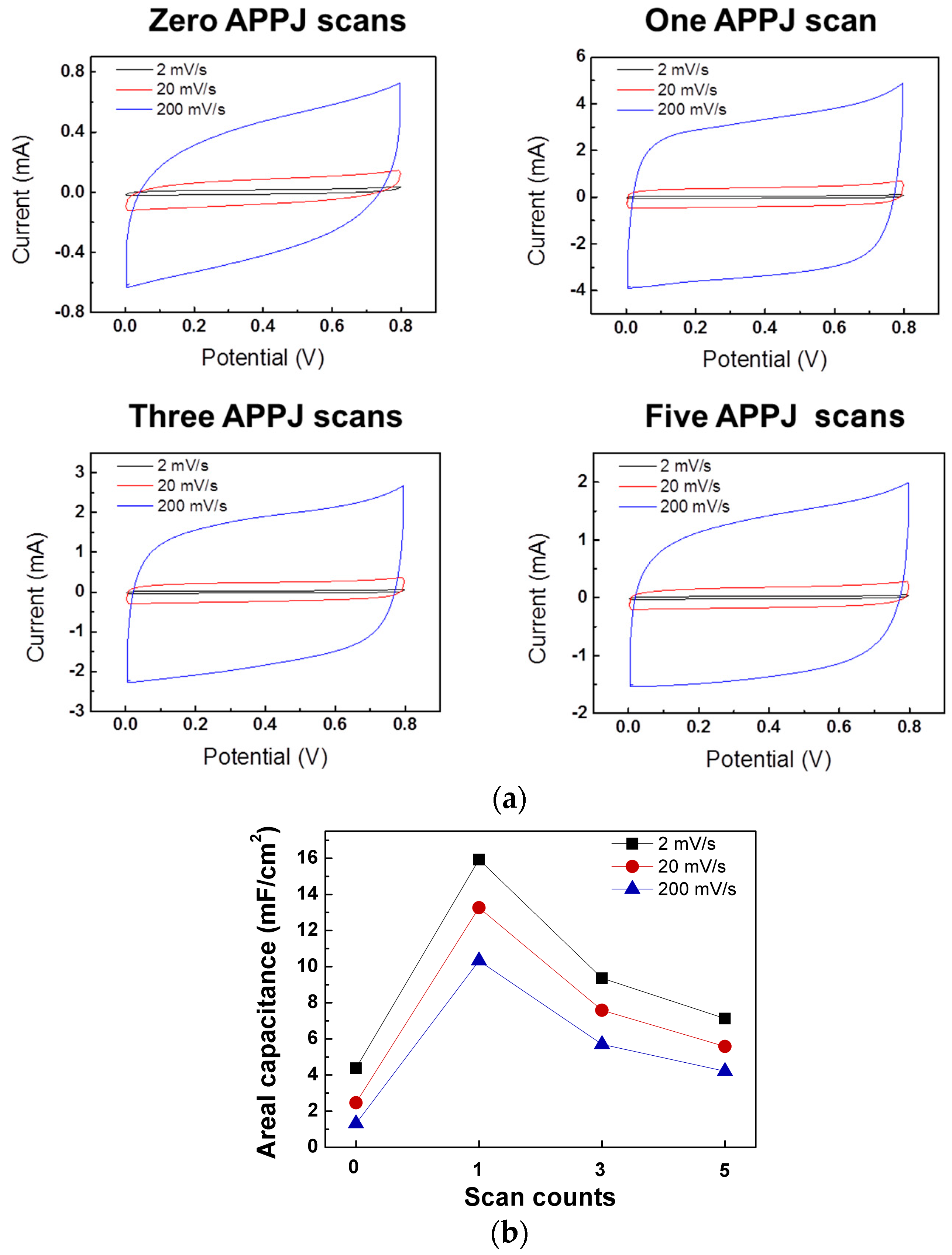
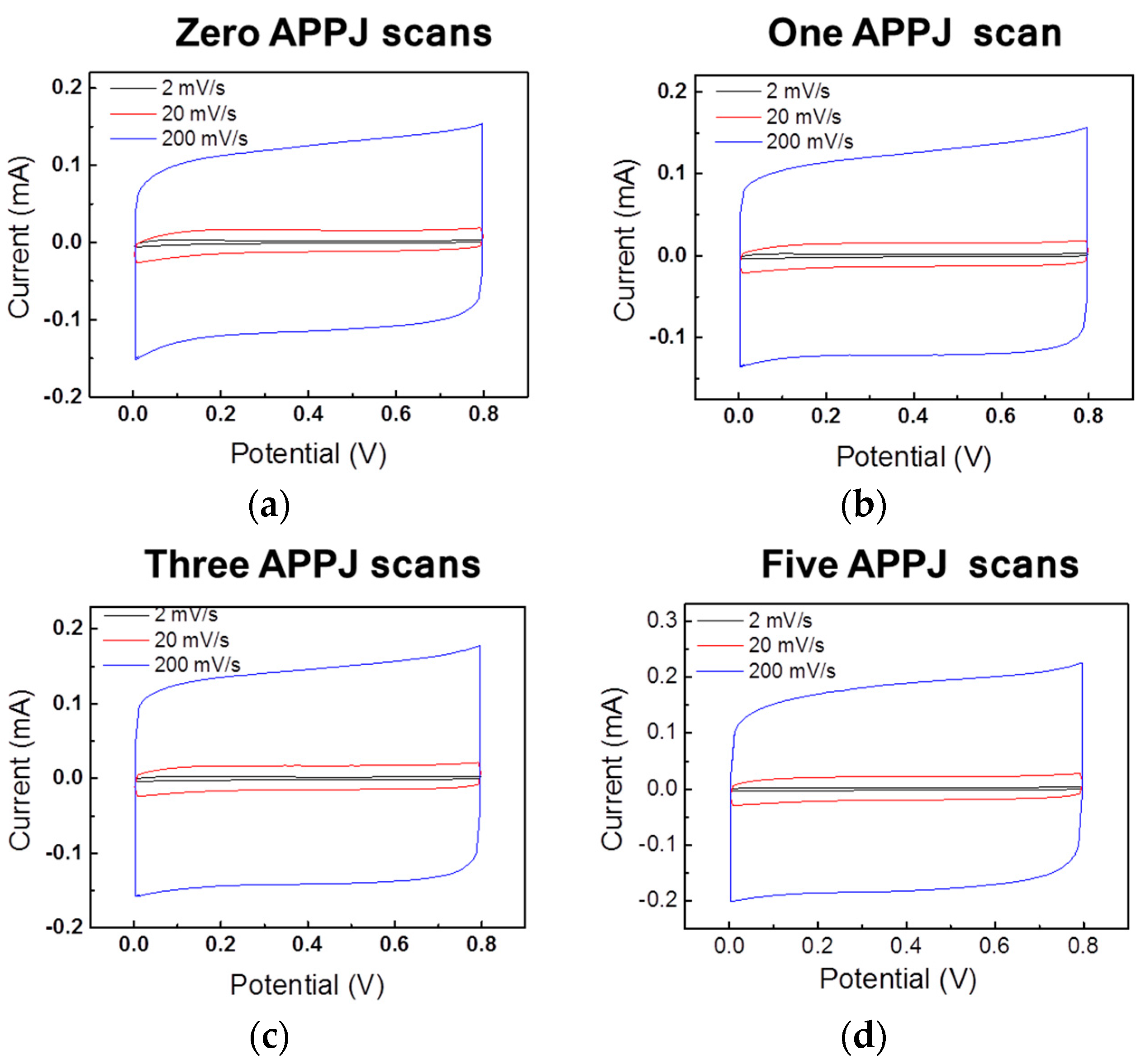
3.6. CV Results of Gel-Electrolyte Supercapacitor

The areal capacitance can be calculated from the CV results based on the following equation [19].
C areal = 1 A v ( V b V a ) V a V b I ( V ) d V
where Careal is the specific capacitance, A is the apparent area of the electrode, v is the potential scan rate, VbVa is the potential scan window and I(V) and V are the response current and voltage under CV operation, respectively.
Figure 7a shows the CV results of gel-electrolyte supercapacitors with rGO pastes on carbon cloth processed by scan-mode APPJ. Figure 7b shows a comparison of the areal capacitance calculated based on the CV results shown in Figure 7a. With one APPJ scan, the areal capacitance reached its maximum values. The same trend is seen for three different potential scan rates. APPJ processing clearly improves the capacitance from 4.38 (zero APPJ scan) to 15.93 mF/cm2 (one APPJ scan), as evaluated at a potential scan rate of 2 mV/s. Further increasing the number of APPJ scan decreased the areal capacitance. This could be attributed to the proper removal of EC while retaining sufficient amount of rGOs. The improved wettability can also lead to better contact between the electrolyte and the electrode, resulting in higher capacitance. Although nitrogen APPJ reactive species react vigorously with both EC and rGOs, EC shows a higher reaction rate [12,22]. Therefore, the proper control of APPJ scan times could be the key to remove a sufficient amount of inactive non-conductive EC, which thereby creates a nanoporous structure to increase the surface area for adsorbed ions in the electrolyte; this could improve the capacitance. Over-calcination by APPJ could severely damage rGOs, leading to decreased capacitance. Similar results have been observed with liquid electrolyte rGO supercapacitors processed by stationary nitrogen APPJ, in which the APPJ processing time is somewhat equivalent to the role of number of APPJ scans in the present study [18]. The removal of sufficient non-conductive EC also smoothens the charge conduction path, as evidenced by the GCD results in which the charging-discharging curve is not smooth without any APPJ processing (Figure 6). For each supercapacitor, the measured areal capacitance increased as the CV potential scan rate decreased. This observation is attributed to the readier access to the electrolyte ions in the nanopores in response to slower variation of the applied electrical field, that is, slower potential scan rate, in the CV measurement. Although no much difference has been noted by water contact angle measurement and SEM for APPJ-processed rGOs on carbon cloth, significant different contents of surface functional groups have been noted by XPS. The difference in contents of surface functional groups can lead to various surface conditions, resulting in different capacitance values.
Figure 8 shows the CV results of gel-electrolyte supercapacitors made with scan-mode APPJ-processed carbon cloth (without rGO coatings). Table 2 lists the areal capacitance values. The areal capacitance values are all <1 mF/cm2. This indicates that the rGO coating with APPJ processing improves the capacitance values. The major contribution to areal capacitance (for supercapacitors with rGOs coatings) results from the coated rGOs.

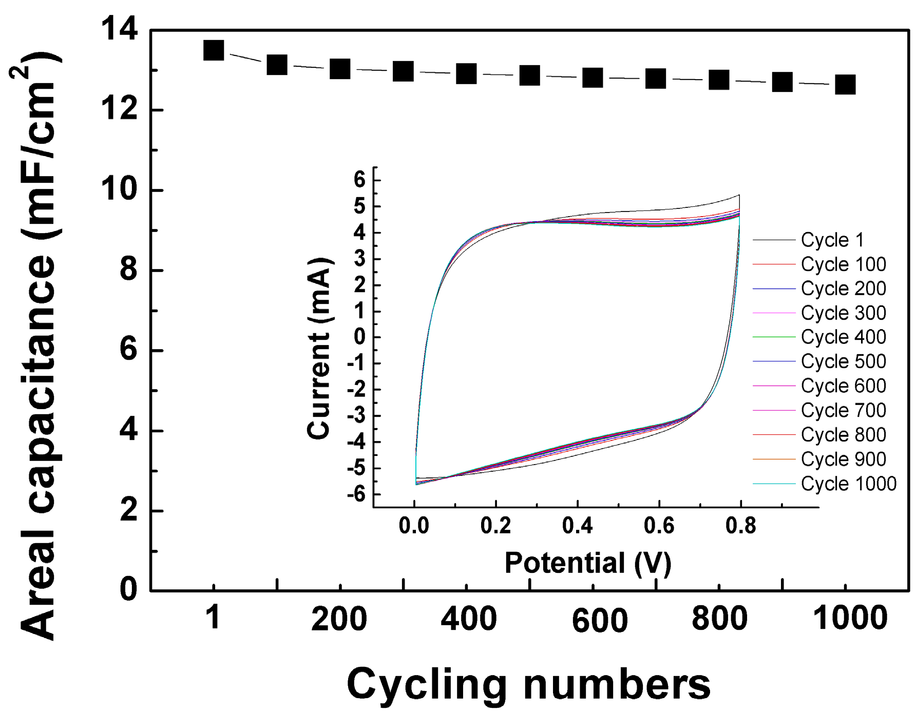
3.7. CV Cycling Stability Test Results of Gel-Electrolyte Supercapacitor

We evaluated the stability of the supercapacitor that showed the best performance (one APPJ scan). Figure 9 shows the cycling stability test results for supercapacitor with one APPJ scan. The capacitance retention rate is ~93% after a 1000-cycle CV test.

4. Conclusions

We perform a feasibility test of scan-mode DC-pulse nitrogen APPJ for gel-electrolyte rGO supercapacitor fabrication. The results suggest the possibility of applying this technique to high-throughput large-area and roll-to-roll processes with higher temperature tolerant substrates such as stainless steel, carbon cloth and willow glass. With a thermal influence duration of ~10 s per scan, the supercapacitor showed best performance with one APPJ scan; this is the most time- and energy-saving fabrication condition. XPS indicates the reduction of the C–O bonding content as the number of APPJ scan increases, indicating the oxidation/decomposition of EC. Using the optimal number of APPJ scan enables proper removal of inactive EC and improved wettability while minimizing the damage caused to rGOs by nitrogen APPJ processing.

Acknowledgments

The authors gratefully acknowledge the funding support from the Ministry of Science and Technology of Taiwan under grant nos. MOST 105-2221-E-002-047-MY3 and MOST 106-2221-E-002-193-MY2. The cleanroom facility is provided by the Nano-Electro-Mechanical-Systems Research Center at National Taiwan University. The authors would like to thank Yuan-Tzu Lee of the Instrumentation Center at National Taiwan University for her assistance with the SEM operation.

Author Contributions

Jian-Zhang Chen designed and instructed the research; Cheng-Che Hsu and I-Chun Cheng assisted in instruction in research; Aliyah R. Hsu and Chen-Yu Liao fabricated and characterized the supercapacitors, as well as analyzed the data about OES and XPS; Hung-Hua Chien conducted experiments and analyzed the data about SEM, water contact angle and XPS; Chia-Chun Lee helped on the experimental setup and XPS data analyses; Jui-Hsuan Tsai helped on the experimental setup and data analyses; Jian-Zhang Chen wrote the paper; All authors commented and revised the manuscript.

Conflicts of Interest

The authors declare no conflict of interest.

References

  1. Schutze, A.; Jeong, J.Y.; Babayan, S.E.; Park, J.; Selwyn, G.S.; Hicks, R.F. The atmospheric-pressure plasma jet: A review and comparison to other plasma sources. IEEE Trans. Plasma Sci. 1998, 26, 1685–1694. [Google Scholar] [CrossRef]
  2. Tendero, C.; Tixier, C.; Tristant, P.; Desmaison, J.; Leprince, P. Atmospheric pressure plasmas: A review. Spectrochim. Acta B 2006, 61, 2–30. [Google Scholar] [CrossRef]
  3. Park, G.Y.; Park, S.J.; Choi, M.Y.; Koo, I.G.; Byun, J.H.; Hong, J.W.; Sim, J.Y.; Collins, G.J.; Lee, J.K. Atmospheric-pressure plasma sources for biomedical applications. Plasma Sources Sci. Technol. 2012, 21, 043001. [Google Scholar] [CrossRef]
  4. Winter, J.; Brandenburg, R.; Weltmann, K.D. Atmospheric pressure plasma jets: An overview of devices and new directions. Plasma Sources Sci. Technol. 2015, 24, 064001. [Google Scholar] [CrossRef]
  5. Nassour, K.; Brahami, M.; Nemmich, S.; Hammadi, N.; Zouzou, N.; Tilmatine, A. New hybrid surface-volume dielectric barrier discharge reactor for ozone generation. IEEE Trans. Ind. Appl. 2017, 53, 2477–2484. [Google Scholar] [CrossRef]
  6. Zhang, H.B.; Li, H.; Fang, M.; Wang, Z.D.; Sang, L.J.; Yang, L.Z.; Chen, Q. Roll-to-roll DBD plasma pretreated polyethylene web for enhancement of al coating adhesion and barrier property. App. Surf. Sci. 2016, 388, 539–545. [Google Scholar] [CrossRef]
  7. Homola, T.; Shekargoftar, M.; Dzik, P.; Krumpolec, R.; Durasova, Z.; Vesely, M.; Cernak, M. Low-temperature (70 °C) ambient air plasma-fabrication of inkjet-printed mesoporous TiO2 flexible photoanodes. Flex. Print. Electron. 2017, 2, 035010. [Google Scholar] [CrossRef]
  8. Kelly-Wintenberg, K.; Sherman, D.M.; Tsai, P.P.; Gadri, R.B.; Karakaya, F.; Chen, Z.; Roth, J.R.; Montie, T.C. Air filter sterilization using a one atmosphere uniform glow discharge plasma (the volfilter). IEEE Trans. Plasma Sci. 2000, 28, 64–71. [Google Scholar] [CrossRef]
  9. Gaunt, L.F.; Beggs, C.B.; Georghiou, G.E. Bactericidal action of the reactive species produced by gas-discharge nonthermal plasma at atmospheric pressure: A review. IEEE Trans. Plasma Sci. 2006, 34, 1257–1269. [Google Scholar] [CrossRef]
  10. Homma, T.; Furuta, M.; Takemura, Y. Inactivation of Escherichia coli using the atmospheric pressure plasma jet of Ar gas. Jpn. J. Appl. Phys. 2013, 52, 036201. [Google Scholar] [CrossRef]
  11. Lee, H.W.; Kim, M.S.; Won, I.H.; Yun, G.S.; Lee, J.K. Self-prevention of instability in a low-power microwave Ar plasma jet for biomedical applications. J. Phys. D Appl. Phys. 2015, 48, 155203. [Google Scholar] [CrossRef]
  12. Liu, H.-W.; Liang, S.-P.; Wu, T.-J.; Chang, H.; Kao, P.-K.; Hsu, C.-C.; Chen, J.-Z.; Chou, P.-T.; Cheng, I.-C. Rapid atmospheric pressure plasma jet processed reduced graphene oxide counter electrodes for dye-sensitized solar cells. ACS Appl. Mater. Interfaces 2014, 6, 15105–15112. [Google Scholar] [CrossRef] [PubMed]
  13. Wu, T.-H.; Cheng, I.-C.; Hsu, C.-C.; Chen, J.-Z. UV photocurrent responses of ZnO and MgZnO/ZnO processed by atmospheric pressure plasma jets. J. Alloy. Compd. 2015, 628, 68–74. [Google Scholar] [CrossRef]
  14. Wu, T.-J.; Chou, C.-Y.; Hsu, C.-M.; Hsu, C.-C.; Chen, J.-Z.; Cheng, I.-C. Ultrafast synthesis of continuous au thin films from chloroauric acid solution using an atmospheric pressure plasma jet. RSC Adv. 2015, 5, 99654–99657. [Google Scholar] [CrossRef]
  15. Chen, J.-Z.; Wang, C.; Hsu, C.-C.; Cheng, I.-C. Ultrafast synthesis of carbon-nanotube counter electrodes for dye-sensitized solar cells using an atmospheric-pressure plasma jet. Carbon 2016, 98, 34–40. [Google Scholar] [CrossRef]
  16. Xu, C.-H.; Chen, J.-Z. Atmospheric-pressure plasma jet processed SnO2/CNT nanocomposite for supercapacitor application. Ceram. Int. 2016, 42, 14287–14291. [Google Scholar] [CrossRef]
  17. Xu, C.-H.; Shen, P.-Y.; Chiu, Y.-F.; Yeh, P.-W.; Chen, C.-C.; Chen, L.-C.; Hsu, C.-C.; Cheng, I.-C.; Chen, J.-Z. Atmospheric pressure plasma jet processed nanoporous Fe2O3/CNT composites for supercapacitor application. J. Alloy. Compd. 2016, 676, 469–473. [Google Scholar] [CrossRef]
  18. Kuok, F.-H.; Liao, C.-Y.; Wan, T.-H.; Yeh, P.-W.; Cheng, I.-C.; Chen, J.-Z. Atmospheric pressure plasma jet processed reduced graphene oxides for supercapacitor application. J. Alloy. Compd. 2017, 692, 558–562. [Google Scholar] [CrossRef]
  19. Yang, C.-H.; Kuok, F.-H.; Liao, C.-Y.; Wan, T.-H.; Chen, C.-W.; Hsu, C.-C.; Cheng, I.-C.; Chen, J.-Z. Flexible reduced graphene oxide supercapacitor fabricated using a nitrogen DC-pulse atmospheric-pressure plasma jet. Mater. Res. Express 2017, 4, 025504. [Google Scholar] [CrossRef]
  20. Kuok, F.-H.; Kan, K.-Y.; Yu, I.-S.; Chen, C.-W.; Hsu, C.-C.; Cheng, I.-C.; Chen, J.-Z. Application of atmospheric-pressure plasma jet processed carbon nanotubes to liquid and quasi-solid-state gel electrolyte supercapacitors. Appl. Surf. Sci. 2017, 425, 321–328. [Google Scholar] [CrossRef]
  21. Wan, T.-H.; Chiu, Y.-F.; Chen, C.-W.; Hsu, C.-C.; Cheng, I.-C.; Chen, J.-Z. Atmospheric-pressure plasma jet processed Pt-decorated reduced graphene oxides for counter-electrodes of dye-sensitized solar cells. Coatings 2016, 6, 44. [Google Scholar] [CrossRef]
  22. Chen, J.-Z.; Hsu, C.-C.; Wang, C.; Liao, W.-Y.; Wu, C.-H.; Wu, T.-J.; Liu, H.-W.; Chang, H.; Lien, S.-T.; Li, H.-C. Rapid atmospheric-pressure-plasma-jet processed porous materials for energy harvesting and storage devices. Coatings 2015, 5, 26–38. [Google Scholar] [CrossRef]
  23. Liu, L.; Ye, D.; Yu, Y.; Liu, L.; Wu, Y. Carbon-based flexible micro-supercapacitor fabrication via mask-free ambient micro-plasma-jet etching. Carbon 2017, 111, 121–127. [Google Scholar] [CrossRef]
  24. Jeong, J.Y.; Babayan, S.E.; Tu, V.J.; Park, J.; Henins, I.; Hicks, R.F.; Selwyn, G.S. Etching materials with an atmospheric-pressure plasma jet. Plasma Sources Sci. Technol. 1998, 7, 282–285. [Google Scholar] [CrossRef]
  25. Jeong, J.Y.; Babayan, S.E.; Schutze, A.; Tu, V.J.; Park, J.; Henins, I.; Selwyn, G.S.; Hicks, R.F. Etching polyimide with a nonequilibrium atmospheric-pressure plasma jet. J. Vac. Sci. Technol. A 1999, 17, 2581–2585. [Google Scholar] [CrossRef]
  26. Surowsky, B.; Schluter, O.; Knorr, D. Interactions of non-thermal atmospheric pressure plasma with solid and liquid food systems: A review. Food Eng. Rev. 2015, 7, 82–108. [Google Scholar] [CrossRef]
  27. Misra, N.N.; Schluter, O.; Cullen, P.J. Cold Plasma in Food and Agriculture: Fundamentals and Applications; Academic Press: Cambridge, MA, USA, 2016. [Google Scholar]
  28. Ramazzina, I.; Tappi, S.; Rocculi, P.; Sacchetti, G.; Berardinelli, A.; Marseglia, A.; Rizzi, F. Effect of cold plasma treatment on the functional properties of fresh-cut apples. J. Agric. Food Chem. 2016, 64, 8010–8018. [Google Scholar] [CrossRef] [PubMed]
  29. Kusano, Y. Atmospheric pressure plasma processing for polymer adhesion: A review. J. Adhes. 2014, 90, 755–777. [Google Scholar] [CrossRef]
  30. Homola, T.; Matousek, J.; Medvecka, V.; Zahoranova, A.; Kormunda, M.; Kovacik, D.; Cernak, M. Atmospheric pressure diffuse plasma in ambient air for ITO surface cleaning. Appl. Surf. Sci. 2012, 258, 7135–7139. [Google Scholar] [CrossRef]
  31. Kim, K.N.; Lee, S.M.; Mishra, A.; Yeom, G.Y. Atmospheric pressure plasmas for surface modification of flexible and printed electronic devices: A review. Thin Solid Films 2016, 598, 315–334. [Google Scholar] [CrossRef]
  32. Penkov, O.V.; Khadem, M.; Lim, W.S.; Kim, D.E. A review of recent applications of atmospheric pressure plasma jets for materials processing. J. Coat. Technol. Res. 2015, 12, 225–235. [Google Scholar] [CrossRef]
  33. Li, F.; Song, J.; Yang, H.; Gan, S.; Zhang, Q.; Han, D.; Ivaska, A.; Niu, L. One-step synthesis of graphene/SnO2 nanocomposites and its application in electrochemical supercapacitors. Nanotechnology 2009, 20, 455602. [Google Scholar] [CrossRef] [PubMed]
  34. Zhang, D.C.; Zhang, X.; Chen, Y.; Wang, C.H.; Ma, Y.W. An environment-friendly route to synthesize reduced graphene oxide as a supercapacitor electrode material. Electrochim. Acta 2012, 69, 364–370. [Google Scholar] [CrossRef]
  35. Hu, Z.A.; Xie, Y.L.; Wang, Y.X.; Mo, L.P.; Yang, Y.Y.; Zhang, Z.Y. Polyaniline/SnO2 nanocomposite for supercapacitor applications. Mater. Chem. Phys. 2009, 114, 990–995. [Google Scholar] [CrossRef]
  36. Lu, X.H.; Zheng, D.Z.; Zhai, T.; Liu, Z.Q.; Huang, Y.Y.; Xie, S.L.; Tong, Y.X. Facile synthesis of large-area manganese oxide nanorod arrays as a high-performance electrochemical supercapacitor. Energy Environ. Sci. 2011, 4, 2915–2921. [Google Scholar] [CrossRef]
  37. Davies, A.; Audette, P.; Farrow, B.; Hassan, F.; Chen, Z.; Choi, J.-Y.; Yu, A. Graphene-based flexible supercapacitors: Pulse-electropolymerization of polypyrrole on free-standing graphene films. J. Phys. Chem. C 2011, 115, 17612–17620. [Google Scholar] [CrossRef]
  38. Choi, B.G.; Chang, S.-J.; Kang, H.-W.; Park, C.P.; Kim, H.J.; Hong, W.H.; Lee, S.; Huh, Y.S. High performance of a solid-state flexible asymmetric supercapacitor based on graphene films. Nanoscale 2012, 4, 4983–4988. [Google Scholar] [CrossRef] [PubMed]
  39. Huang, Y.; Liang, J.; Chen, Y. An overview of the applications of graphene-based materials in supercapacitors. Small 2012, 8, 1805–1834. [Google Scholar] [CrossRef] [PubMed]
  40. Geim, A.K.; Novoselov, K.S. The rise of graphene. Nat. Mater. 2007, 6, 183–191. [Google Scholar] [CrossRef] [PubMed]
  41. Zhang, L.-S.; Liang, X.-Q.; Song, W.-G.; Wu, Z.-Y. Identification of the nitrogen species on N-doped graphene layers and Pt/NG composite catalyst for direct methanol fuel cell. Phys. Chem. Chem. Phys. 2010, 12, 12055–12059. [Google Scholar] [CrossRef] [PubMed]
  42. Yang, C.-H.; Chen, C.-W.; Lin, Y.-K.; Yeh, Y.-C.; Hsu, C.-C.; Fan, Y.-J.; Yu, S.; Chen, J.-Z. Atmospheric-pressure plasma jet processed carbon-based electrochemical sensor integrated with a 3D-printed microfluidic channel. J. Electrochem. Soc. 2017, 164, B534–B541. [Google Scholar] [CrossRef]
  43. Zhang, H.; Su, H.; Zhang, L.; Zhang, B.; Chun, F.; Chu, X.; He, W.; Yang, W. Flexible supercapacitors with high areal capacitance based on hierarchical carbon tubular nanostructures. J. Power Sources 2016, 331, 332–339. [Google Scholar] [CrossRef]
  44. Ng, K.C.; Zhang, S.; Peng, C.; Chen, G.Z. Individual and bipolarly stacked asymmetrical aqueous supercapacitors of CNTs/SnO2 and CNTs/MnO2 nanocomposites. J. Electrochem. Soc. 2009, 156, A846–A853. [Google Scholar] [CrossRef]
  45. Bo, Z.; Zhu, W.; Tu, X.; Yang, Y.; Mao, S.; He, Y.; Chen, J.; Yan, J.; Cen, K. Instantaneous reduction of graphene oxide paper for supercapacitor electrodes with unimpeded liquid permeation. J. Phys. Chem. C 2014, 118, 13493–13502. [Google Scholar] [CrossRef]
  46. Alotaibi, F.; Tung, T.T.; Nine, M.J.; Kabiri, S.; Moussa, M.; Tran, D.N.H.; Losic, D. Scanning atmospheric plasma for ultrafast reduction of graphene oxide and fabrication of highly conductive graphene films and patterns. Carbon 2018, 127, 113–121. [Google Scholar] [CrossRef]
  47. Hsu, C.C.; Yang, Y.J. The increase of the jet size of an atmospheric-pressure plasma jet by ambient air control. IEEE Trans. Plasma Sci. 2010, 38, 496–499. [Google Scholar]
  48. Hsu, Y.-W.; Yang, Y.-J.; Wu, C.-Y.; Hsu, C.-C. Downstream characterization of an atmospheric pressure pulsed arc jet. Plasma Chem. Plasma Process. 2010, 30, 363–372. [Google Scholar] [CrossRef]
  49. Hsu, C.-C.; Wu, C.-Y. Electrical characterization of the glow-to-arc transition of an atmospheric pressure pulsed arc jet. J. Phys. D Appl. Phys. 2009, 42, 215202. [Google Scholar] [CrossRef]
  50. Hsu, C.-C.; Wu, C.-Y.; Chen, C.-W.; Cheng, W.-C. Mode transition of an atmospheric pressure arc plasma jet sustained by pulsed DC power. Jpn. J. Appl. Phys. 2009, 48, 076002. [Google Scholar] [CrossRef]
  51. Kuok, F.-H.; Liao, C.-Y.; Chen, C.-W.; Hao, Y.-C.; Yu, I.-S.; Chen, J.-Z. Screen-printed SnO2/CNT quasi-solid-state gel-electrolyte supercapacitor. Mater Res Express 2017, 4, 115501. [Google Scholar] [CrossRef]
  52. Wright, A.N.; Wrinkler, C.A. Active Nitrogen; Academic Press: Cambridge, MA, USA, 1968. [Google Scholar]
  53. Jiang, Z.; Jiang, Z.; Chen, W. The role of holes in improving the performance of nitrogen-doped holey graphene as an active electrode material for supercapacitor and oxygen reduction reaction. J. Power Sources 2014, 251, 55–65. [Google Scholar] [CrossRef]
  54. Qie, L.; Chen, W.; Xu, H.; Xiong, X.; Jiang, Y.; Zou, F.; Hu, X.; Xin, Y.; Zhang, Z.; Huang, Y. Synthesis of functionalized 3D hierarchical porous carbon for high-performance supercapacitors. Energy Environ. Sci. 2013, 6, 2497–2504. [Google Scholar] [CrossRef]
  55. Gao, Z.; Liu, X.; Chang, J.; Wu, D.; Xu, F.; Zhang, L.; Du, W.; Jiang, K. Graphene incorporated, N doped activated carbon as catalytic electrode in redox active electrolyte mediated supercapacitor. J. Power Sources 2017, 337, 25–35. [Google Scholar] [CrossRef]
  56. Wan, T.-H.; Lee, C.-C.; Chen, C.-W.; Hsu, C.-C.; Cheng, I.-C.; Chen, J.-Z. A comparison study of furnace and atmospheric-pressure-plasma jet calcined Pt-decorated reduced graphene oxides for dye-sensitized solar cell application. J. Electrochem. Soc. 2017, 164, H931–H935. [Google Scholar] [CrossRef]
  57. Luo, G.; Liu, L.; Zhang, J.; Li, G.; Wang, B.; Zhao, J. Hole defects and nitrogen doping in graphene: Implication for supercapacitor applications. ACS Appl. Mater. Interfaces 2013, 5, 11184–11193. [Google Scholar] [CrossRef] [PubMed]
Figure 1. (a) DC-pulse APPJ setup with a motorized scanning stage; (b) Temperature evolution of the substrate with five scans; (c) Image of scan-mode nitrogen APPJ during operation.
Coatings 08 00052 g001
Figure 2. OES of plasma during (a) scan-mode and (b) stationary APPJ processing.
Coatings 08 00052 g002
Figure 3. SEM images of the APPJ-processed rGOs on carbon cloth.
Coatings 08 00052 g003
Figure 4. Water contact angle measurement results of APPJ-processed rGOs on carbon cloth.
Coatings 08 00052 g004
Figure 5. XPS spectra of (a) C 1s, (b) N 1s, and (c) O 1s for screen-printed rGOs on carbon cloth with/without APPJ treatment.
Coatings 08 00052 g005aCoatings 08 00052 g005b
Figure 6. GCD results of gel-electrolyte supercapacitors made with rGO pastes on carbon cloth processed by scan-mode APPJ: (a) zero APPJ scans; (b) one APPJ scan; (c) three APPJ scans; and (d) five APPJ scans.
Coatings 08 00052 g006
Figure 7. (a) CV results of gel-electrolyte supercapacitors made with rGO pastes on carbon cloth processed by scan-mode APPJ; (b) Comparison of areal capacitance calculated from CV results in Figure 7a.
Coatings 08 00052 g007
Figure 8. CV results of gel-electrolyte supercapacitors made with scan-mode APPJ processed carbon cloth (without rGO coatings): (a) zero APPJ scans; (b) one APPJ scan; (c) three APPJ scans; (d) five APPJ scans.
Coatings 08 00052 g008
Figure 9. CV stability result of gel-electrolyte supercapacitor with one APPJ scan.
Coatings 08 00052 g009
Table 1. Bonding contents analyzed from XPS spectra shown in Figure 5.
Bonding Configuration Bonding Content
Zero APPJ ScansOne APPJ ScanThree APPJ ScansFive APPJ Scans
C 1s
C–C (284.5 eV)45.00%59.24%70.08%70.66%
C–O (286.3 eV)51.40%31.30%18.81%18.64%
C=O (288.5 eV)3.60%9.46%11.11%10.70%
N 1s
Pyridinic-N (398.3 eV)54.18%62.62%
Pyrrolic-N (399.9 eV)38.65%25.76%
Graphitic-N (400.9 eV)7.17%11.62%
O 1s
O=C (531.1 eV)8.00%16.00%33.03%24.24%
C–OH (532.3 eV)73.50%67.20%23.23%36.30%
–COOH (533.3 eV)18.50%16.80%43.74%39.46%
Table 2. Areal capacitance of gel-electrolyte supercapacitors made with scan-mode APPJ processed carbon cloth (without rGO coatings).
Potential Scan RateZero APPJ ScansOne APPJ ScanThree APPJ ScansFive APPJ Scans
2 mV/s0.63 mF/cm20.58 mF/cm20.65 mF/cm20.83 mF/cm2
20 mV/s0.47 mF/cm20.46 mF/cm20.53 mF/cm20.68 mF/cm2
200 mV/s0.39 mF/cm20.40 mF/cm20.47 mF/cm20.59 mF/cm2

