Article

Alkoxylated β-Naphthol as an Additive for Tin Plating from Chloride and Methane Sulfonic Acid Electrolytes

1
Hirtenberger Engineered Surfaces GmbH, Leobersdorfer Strasse 31-33, A-2552 Hirtenberg, Austria
2
Department of Physical Chemistry, University of Vienna, Währinger Strasse 42, A-1090 Vienna, Austria
3
Department of Industrial and Materials Science, Chalmers University of Technology, Rännvägen 2A, SE-412 96 Gothenburg, Sweden
*
Author to whom correspondence should be addressed.
Coatings 2018, 8(2), 79; https://doi.org/10.3390/coatings8020079
Submission received: 7 December 2017 / Revised: 16 February 2018 / Accepted: 19 February 2018 / Published: 21 February 2018
(This article belongs to the Special Issue Thin Films and Patterned Structures by Electrochemical Methods)

Abstract

:
β-naphthol was one of the first additives introduced for smooth and homogeneous tin electrodeposition. Although it can be oxidized under the plating conditions, forming either 1,2-napthoquinone or polymeric materials based on naphthioxides, it is still in use. In this work, an investigation of its more stable form, alkoxylated β-naphthol (ABN), on tin plating is undertaken. For this purpose, chloride based (pH ~5) and methane sulfonic acid (MSA, pH ~0.5) electrolytes, including ABN, were prepared. Reaction kinetics were studied by polarization, Tafel measurements, and cyclic voltammetry. Tin electrodeposits were obtained on flat brass substrates. Surface morphology and preferred crystal orientation were studied by Scanning Electron Microscopy (SEM) and X-ray Diffraction (XRD). In both studied electrolytes ABN acts as an inhibitor but in the case of the chloride electrolyte it is more pronounced. In the MSA electrolyte this effect was overlaid by the presence of tin-citrate complexes. In the chloride-based electrolyte, ABN has a grain refining effect, while in the MSA electrolyte an increase of ABN concentration leads to a slight enlargement of the average grain size. X-ray analysis shows a constant decrease of the (101) intensity with increasing concentration of ABN for the sample deposited from both baths.

1. Introduction

The electrochemistry of tin in an acidic electrolyte has been studied for several decades. Nevertheless, both the role of organic additives for optimized brightness, gloss and hardness, and also their effect on the electrochemical mechanism is still an open field of research. Due to their solderability and chemical inertness, tin electrodeposits are industrially used in several applications. Tin is one of few metals suitable in an unalloyed metallic form for contact with food, due to its non-toxicity and corrosion resistance [1]. In addition, due to its solderability it is also extensively used in the electronics industry [2].
Tin can be plated from both alkaline and acidic solutions [3]. Alkaline electrolytes are based on sodium [4] or potassium stannate [5,6]. They have excellent throwing power and simple compositions, and satisfactory deposits can be obtained from a wide range of tin concentrations. However, the application of the alkaline electrolytes has several drawbacks. Due to the stannate form of tin present in the alkaline electrolytes, the electrochemical equivalent is only half of that in an acid bath. Higher cathodic current densities can be achieved only at elevated temperatures (e.g. > 60 °C). Moreover, no bright deposits can be obtained under direct current deposition without using a reflowing post-treatment. Compared to the acidic electroplating solutions, alkaline electrolytes are used less often for tin electrodeposition.
Electrodeposition of tin from acidic solutions is generally done from divalent stannous ions (Sn2+) in a single step:
Sn2+ + 2e → Sn
The electrochemical equivalent is twice that of the alkaline electrolytes. Furthermore, bright coatings can be obtained by using organic additives. Electrolytes are operated at room temperature using a soluble anode. Tin plating from acidic solutions [3] may be performed from sulfuric [7], methane sulfonic [2,8,9,10] or chloridic [11,12] electrolytes. Sulfuric acid is widely used as the basis for tin electrolyte. Usage of methane sulfonic acid (MSA) electrolytes has several advantages over the sulfuric acid one. Methane sulfonic acid based electrolytes are versatile [13], biodegradable [14], have excellent metal salt solubility [15], and they are less corrosive than sulfuric acid. A review of the literature shows that the electrodeposition of tin from chloride baths has not been investigated in detail.
Organic molecules must be added to the electrolytes for a homogenous, compact tin deposition from an acidic solution. Electroplates, originating from pure acidic tin electrolytes, are dendritic and often porous and non-compact [16]. One of the first surfactants and grain refiners introduced to tin electroplating electrolytes, for the purpose of obtaining homogenous and compact layers, was β-naphthol [16]. It is widely used despite the main disadvantage of being easily oxidized under plating conditions. The oxidation of β-naphthol takes place in two steps. In the first step a naphthyloxy radical is created, which can react with water resulting in 1,2-naphthoquinone. A parallel reaction, the creation of a polymeric material, takes place when naphthyloxy radicals react with each other (Figure 1) [17]. A more stable form of this additive could be alkoxylated β-naphthol (ABN, Figure 2), where the hydroxyl group is replaced with the more stable alkoxy group.
The use of ABN has several advantages over the original β-naphthol. First of all, the absence of the free hydroxy group assures higher resistance against oxidation. The second advantage is the higher solubility due to the tensidic properties introduced by the hydrophilic polymeric chain. The effect of ABN on tin plating has not been described in the literature so far.
The aim of this work is to investigate the influence of ABN on the electrodeposition of tin, including the kinetic behavior of the chloride and MSA electrolyte for tin plating with different ABN concentrations, as well as the influence of the additive concentration on the deposit morphology and crystallographic structure.

2. Materials and Methods

2.1. Electrochemical Characterization

To investigate the influence of ABN in the chloride and MSA electrolytes, polarization and Tafel measurements were performed using an IPS PGU 20V-2A-E potentiostat. All the potentials were measured against a Ag/AgCl reference electrode, with pure tin as a counter electrode. Rotating disc measurements (IPS PGU 200148) were performed on a 1 cm2 brass electrode polarising from ca. +200 mV to −800 mV against open circuit potential (OCP) with a polarization rate of 10 mV/s. Tafel measurements were made using 1 cm2 stationary flat brass electrodes by scanning from −300 mV to +300 mV versus OCP with the polarization rate of 10 mV/s. Electrode activation was done by immersion for 30 s into 10% H2SO4 and 5% MSA for chloride and MSA electrolyte, respectively.
Cyclic voltammograms and potentiostatic deposition were carried out using a CHI 760C electrochemical workstation in a closed cell under Ar atmosphere with a three electrode setup. A CHI 101 stationary gold disc electrode (Φ = 2 mm) was used as a working electrode. Gold wire was used as a counter and Ag/AgCl as a reference electrode. Before usage, the gold cathode was polished to a mirror bright finish with 0.05 μm alumina powder and rinsed with deionized water. Cyclic voltammograms were measured at a scan rate of 10 mV/s from the open circuit potential (OCP) in the negative direction. Current density transients were recorded for the chloride electrolyte at the potential −0.8 V for 300 s and for the MSA electrolyte at −0.65 V for 150 s.

2.2. Sn Electrodeposition

Two different electrolytes (the chloride [11] and the MSA electrolyte) were prepared for tin electrodeposition (Table 1). Coatings were deposited on 1cm2 stationary flat brass substrates with direct current for 15 min by an IPS PGU 20V-2A-E potentiostat/galvanostat. The electrode surface activation step was the same as for the Tafel measurements. The electrolyte was kept static or it was agitated by a magnetic stirrer at 250 rpm during the deposition. The chloride electrolyte was operated at 60 °C (pH ~5), while the MSA electrolyte was operated at room temperature (pH ~0.5). In both electrolytes the pH was left unadjusted. The deposition experiments were performed in the chloride based electrolyte at a current density of –0.5 A/dm2 and in the MSA based electrolyte at a current density of –1.5 A/dm2. Tin coatings from both electrolytes containing ABN with a concentration of 0, 0.78, 1.17, 1.56, 2.5, and 3.12 mg/L were deposited and compared.

2.3. Structural Characterization

The electrodeposited tin coatings from both chloride and MSA based electrolytes were characterized using scanning electron microscopy (SEM) and X-ray diffraction (XRD). The surface topography of the electrodeposited tin was investigated by use of SEM imaging of the as-plated surface. A Leo 1550 Gemini FEG-SEM (Zeiss, Oberkochen, Germany) was used to acquire the SEM micrographs. The average grain size of the deposits (l) was estimated by use of the Heyn linear intercept method [18]. Here the mean lineal intercept length, l, is calculated by dividing the line length by the number of intercepted grains. SEM images were all taken at 2000× magnification and a mesh of five vertical and five horizontal lines per image was used. XRD patterns of the coatings were acquired with a Bruker AXS D8 Advance (Bruker AXS Gmbh, Karlsruhe, Germany) using a grazing incidence geometry. The samples were scanned at 40–150° 2θ with CrKα radiation (λ = 2.0821 Å, 35 kV, 40 mA) with the angle of incidence set at 3°. A detector scan mode with step size of 0.05° and a sampling time of 5 s was used at a scan rate of 0.01°/s. The measured spectra were analyzed using Diffrac.suiteEva3.0 and the phases formed identified using the standard PDF-4+ from the ICDD database.

3. Results

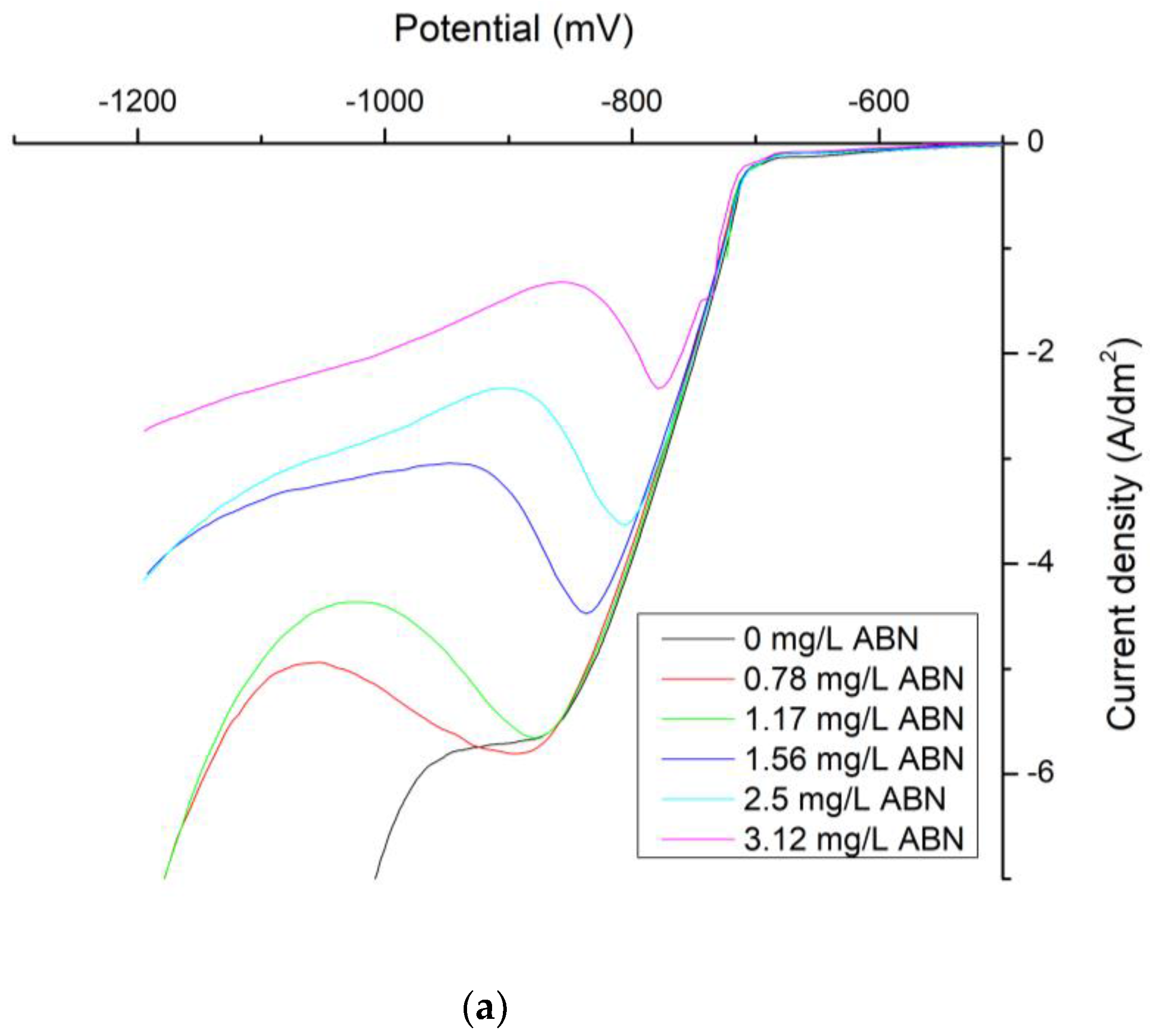
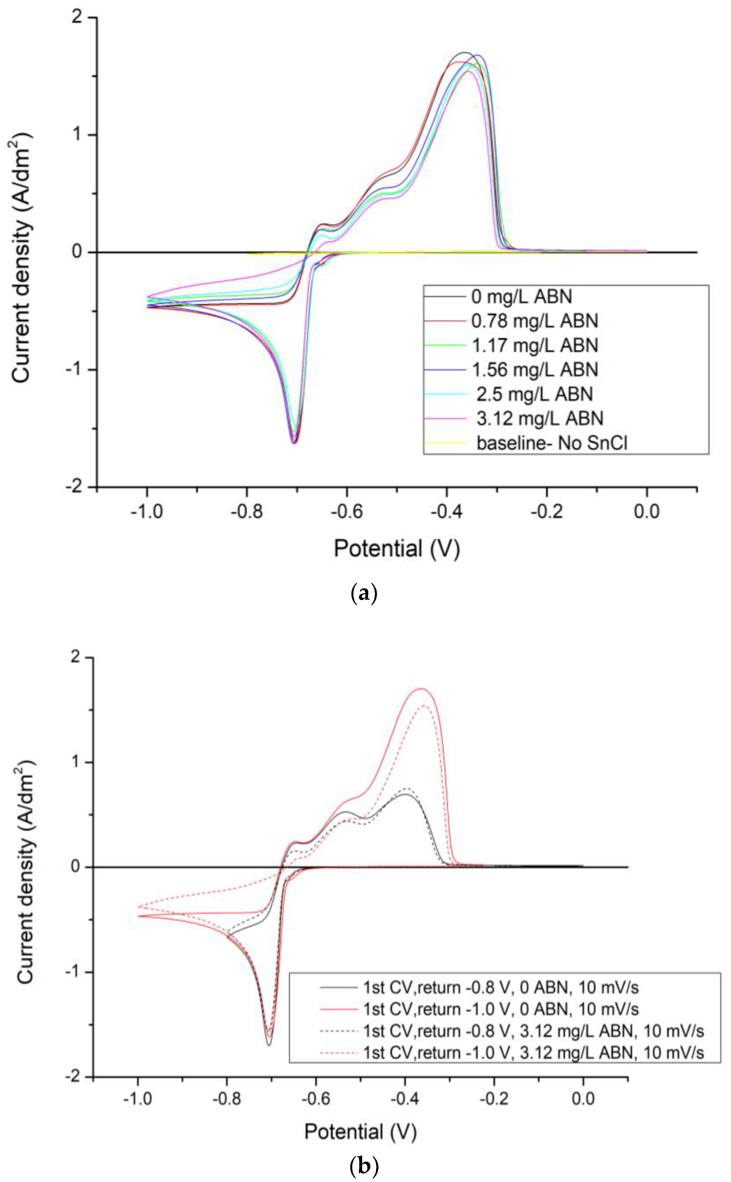
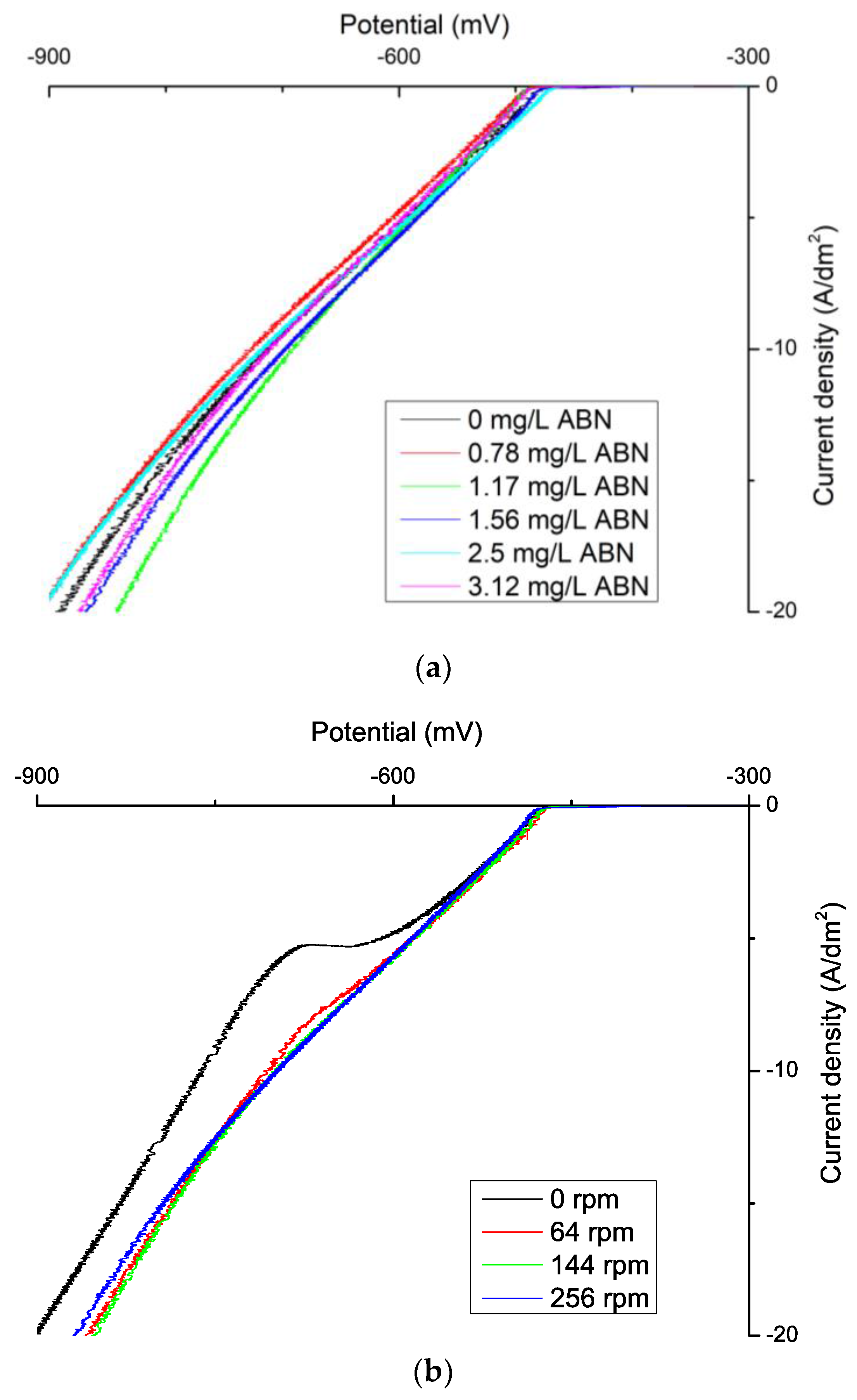
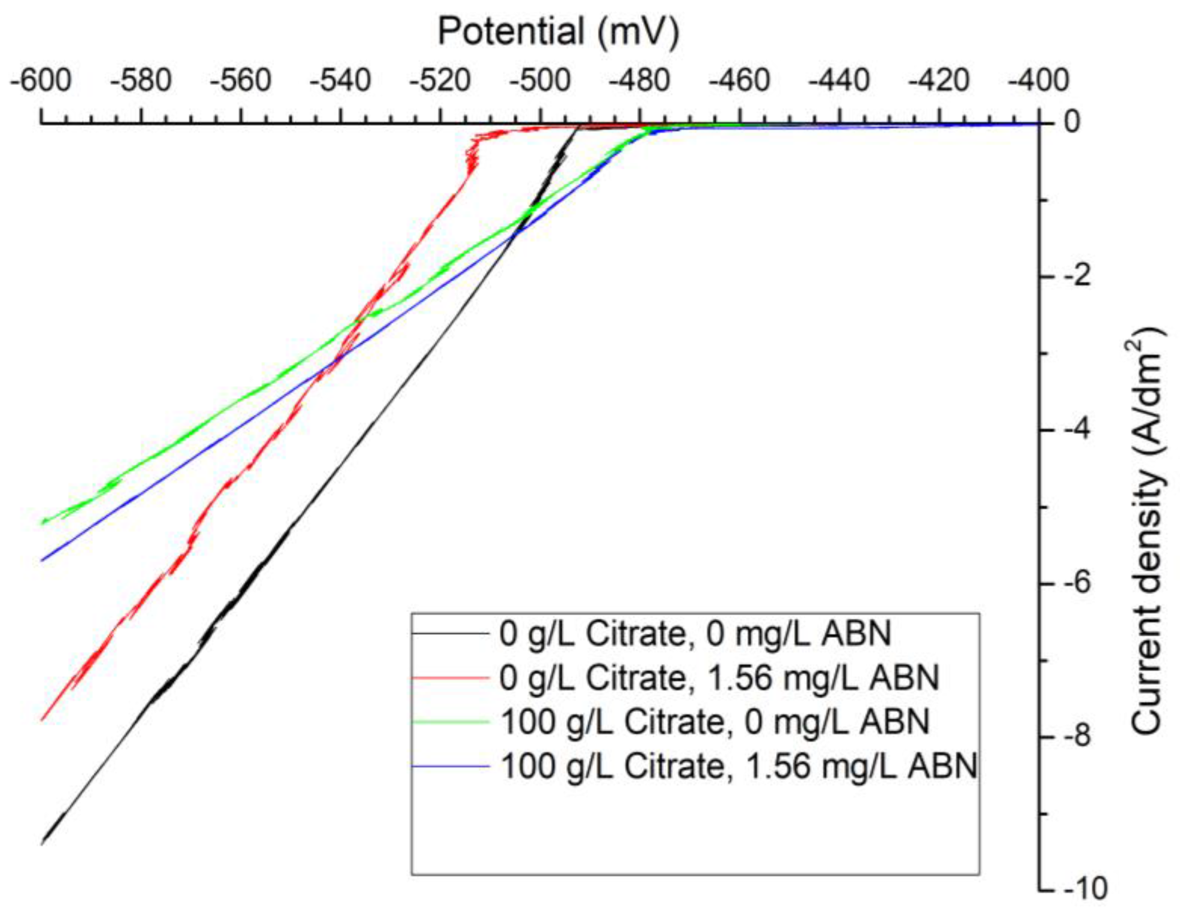
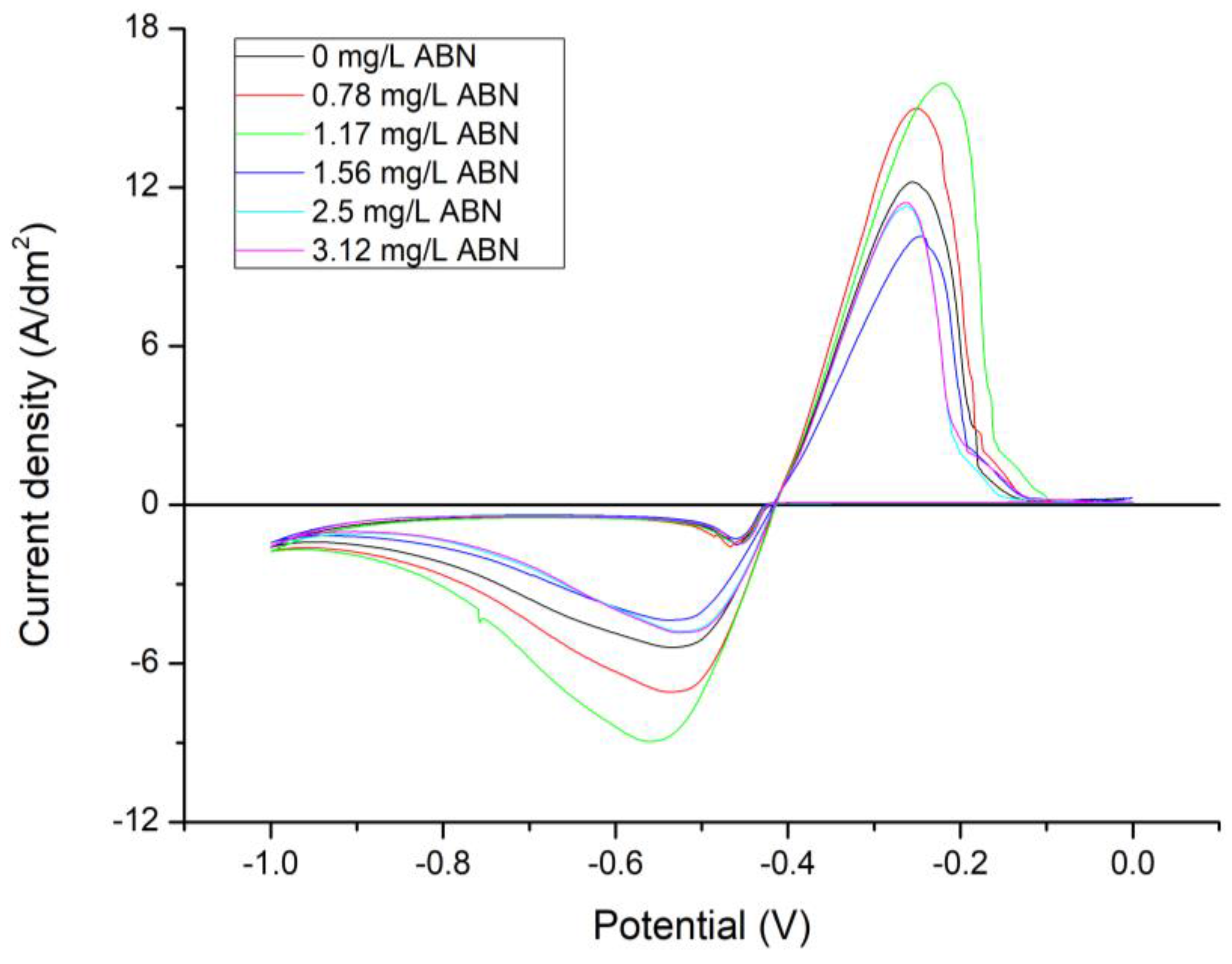
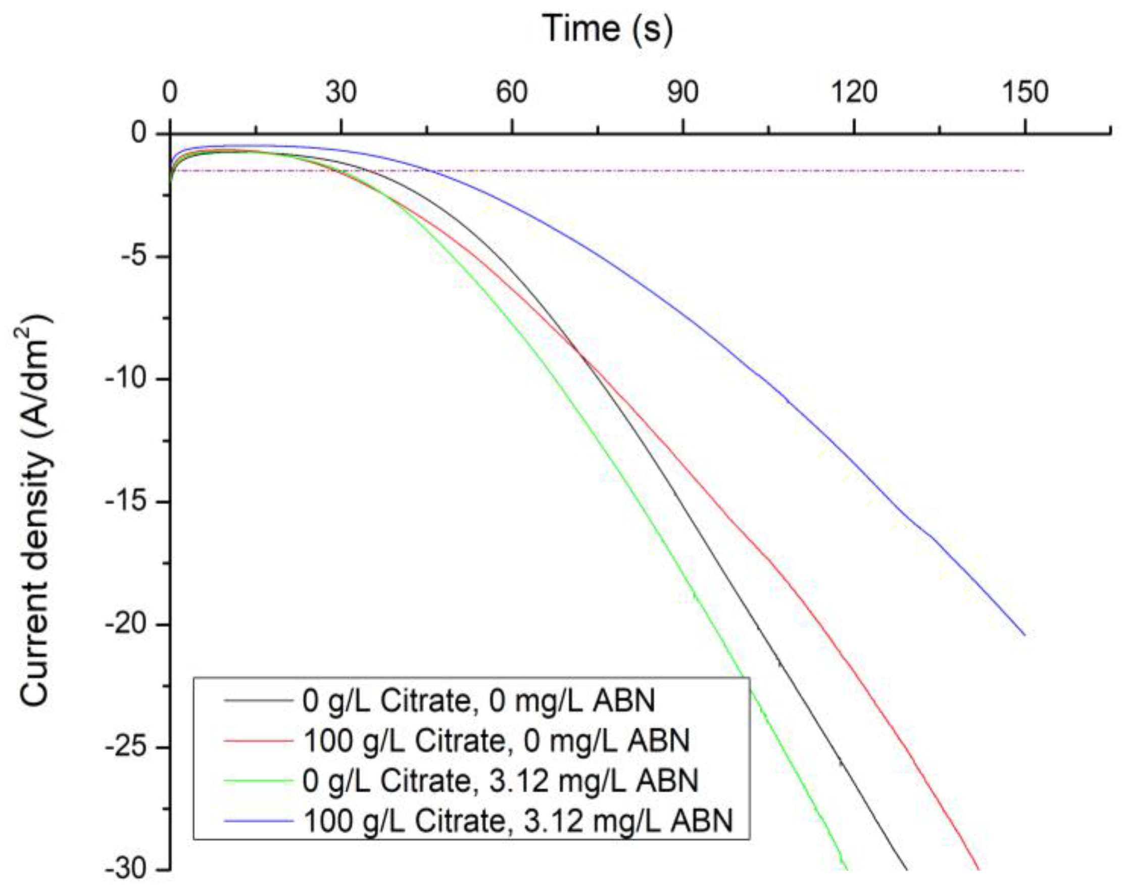
3.1. Electrochemical Characterization

Polarization curves of the electrodeposition of tin from the chloride electrolyte on a rotating disk electrode (RDE) are depicted for various ABN concentrations (Figure 3a) and rotation speeds (Figure 3b). The measured cathodic current density starts to increase at a potential of −700 mV until a plateau, i.e., a limiting current density, is reached at ca. –880 mV in the electrolyte without ABN addition at a rotation speed of 256 rpm. This can be associated with the diffusion-limited reduction of Sn(II). At cathodic potentials higher than −950 mV the current density further increases due to the hydrogen evolution reaction. Addition of ABN (Figure 3a) caused a suppression of H2 evolution within the studied potential window and a decrease in the limiting current density (iL). This behavior indicates that ABN molecules adsorb onto the cathode surface and interfere with the normal metal deposition by blocking the attachment of tin ad-atoms and delaying hydrogen co-evolution.
RDE measurements at higher rotation speeds resulted in rather complex j-U behavior (Figure 3b). The current density in the hydrogen evolution potential region (negative of ca. −900 mV) exhibits a moderate plateau at 0 rpm. The Sn(II) reduction is not strongly affected by the convection changes. Only at the highest speed of 386 rpm, the hydrogen current density drastically increased indicating also a change of pH in the electrode vicinity (not shown).
Cyclic voltammograms (CVs) of the electrodeposited tin from the chloride based electrolyte are depicted for different ABN concentrations in Figure 4a and for different cathodic return points in Figure 4b. The forward cathodic scan exhibits a single current Sn deposition peak (~ −0.7 V) followed by the limiting current density plateau, as reported for the RDE results. The absence of the cross-over of the forward and reverse scan (Figure 4a,b) shows that no overpotential was required for the nucleation process of Sn on Au to be started and there is no bulk deposition [15,19]. In the anodic direction three current peaks were detected (Figure 4a,b). According to the literature [20,21] tin in a slight acidic media undergoes active dissolution and passivation during anodic polarization. The dissolution of tin occurs in two steps:
Sn 0 Sn 2 + + 2 e Sn 4 + + 2 e
Šeruga and Metikoš-Huković [21] studied the oxidation process in citric buffer. With the consideration that most of the dissolute Sn2+ forms soluble chelate complexes Sn(HCit) in solutions with pH = 5 and 6, they proposed several oxidation mechanisms which take place in two steps. In the initial passivation step, Sn(OH)2 is generated, and with further anodic polarization insoluble Sn(OH)4 is created. According to Šeruga and Metikoš-Hukovič [21], the tin passivation process in weak acidic electrolytes can be explained by the Müller passivation model and the film formation process is under ohmic resistance control. The creation of the passivation layer refers to peak I and II of the CV in Figure 4. Considering the drop of the anodic current to 0, peak III refers to the dissolution of the bulk Sn layer. This assumption was confirmed by the measurement with two different cathodic return points −0.8 V and −1 V. When the electrode was polarized to the higher cathodic potential, –1 V, more Sn was deposited, and the Sn dissolution peak III was higher in comparison to that at –0.8 V. The passivation peak heights were independent of the cathodic polarization potential (Figure 4b). The current efficiency was calculated as the ratio between the charges that were used for oxidation and reduction of Sn (Qox/Qred). It was estimated to be 85% for both electrolytes without and with the 3.12 mg/L ABN. On the other hand, the amount of charge used for reduction of Sn was lowered by 10% due to the presence of 3.12 mg/L ABN in the electrolyte. This might indicate that the adsorption of ABN on the cathode surface results either in the specific blocking of the active sites for Sn reduction or in creating a thin layer of ABN on the cathode.
In order to monitor the current for a longer period of time, current density transients were recorded. Resulting jt transients detected for the potential −0.8 V are different in the electrolytes without presence of ABN and with 3.12 mg/L ABN (Figure 5). When no ABN is present in the electrolyte, the current density has a value of about −0.44 A/dm2 in the first 100 s which increases to −0.56 A/dm2 at 300 s. This slight increase might be caused by the increase of the surface area during the deposition. On the other hand, with the presence of 3.12 mg/L ABN, a much lower current flows at the potential of −0.8 V. This means that the addition of ABN to the electrolyte changes the composition of the Helmholtz double layer. Current exponential decay reaches a plateau of −0.1 A/dm2 after 100 s of electrodeposition. This indicates the inhibition effect of ABN and that the electrode blocking process reaches equilibrium after 100 s of electrodeposition.
The results from the Tafel measurements confirmed that ABN acts as a highly effective inhibitor in the chloride electrolyte. The presence of 0.5 mg/L of the additive in the electrolyte decreases the exchange current density (j0) to about 50% of its initial value, i.e., from 7.08 to 3.31 mA/cm2. At the concentration of 0.78 mg/L, ABN acts as an inhibitor at the surface of the electrode and j0 is one order of magnitude lower than in the case when no ABN additive is present (Table 2). A significant decrease of the cathodic slope, from −0.0007 to −0.0042 mV, was detected due to the addition of 0.78 mg/L ABN into the electrolyte. With further increase of the ABN concentration, the cathodic Tafel slope did not change significantly. The high values of the Tafel slopes in the additive-free-electrolyte were described by Martyak and Seefeld [10] as a diffusion controlled reduction process. Moreover, they observed a change of the reduction process from a diffusion controlled to a kinetically controlled due to the adsorption of additives on the cathode surface and the decrease of the Tafel slope. This would indicate, that in the case of MSA electrolyte, the threshold value of ABN concentration for changing the character of the reduction process could be found in the range between 0.5 and 0.78 mg/L. Parallel shifts in the linear logarithmic part of the Tafel lines with no change in the Tafel slopes were detected with an ABN concentration higher than 0.78 mg/L. Based on the observation from Vračar and Dražić [22], such a shift indicates the blocking effect of the additive.
Polarization curves of the electrodeposition of tin from the MSA electrolyte on a RDE are depicted for various ABN concentrations (Figure 6a) and rotation speeds (Figure 6b). Electrodeposition of tin in this case sets in at a potential of −600 mV vs Ag/AgCl. Due to the higher Sn2+ concentration and high ion mobility in this electrolyte, a limiting current density plateau was found only in the case of a static electrode at −5 A/dm2 (Figure 6b). With the introduction of convection, the current density of Sn deposition is shifted to more positive potentials (Figure 6b) and the limiting current density plateau is no longer visible. With the addition of ABN, cathodic current is not suppressed as occurs in the chloride based electrolyte (Figure 6a).
For better understanding of the ABN in the MSA electrolyte, polarization, Tafel measurements and galvanostatic deposition from the additive and citrate free Sn MSA based electrolyte system were performed. The results were compared with the initial MSA electrolyte containing 100g/L of tri-sodium citrate (Figure 7).
The effect of various organic additives e.g. Tritons and polyglycols, on the kinetics of Sn plating has already been studied by Meibuhr et al. [23]. They observed an increment of the electrode polarization due to the adsorption of nonionic additive on the surface of the cathode. In our case a 15 mV increase in the electrode polarization was detected due to the presence of only 1.56 mg/L ABN in the citrate free electrolyte (Figure 7). The polarization was not dependent on the rotation speed of the RDE (not shown). This might indicate that ABN adsorption on the cathode is a kinetically controlled action. The effect of the citrate ions in the MSA electrolyte appears to be rather diverse. It is known, that citrate ions in the MSA electrolyte form several types of complexes with Sn(II) ions [24,25]. This might indicate the formation of relatively stable citrate complexes that lead to an increase in the polarization at the higher potentials for the deposition reaction of the active tin species (Figure 7). On the other hand, the presence of citrate shifts the electrode polarization potential into the anodic direction, which is in contradiction to the character of the complexing agent (Figure 7).
Cyclic voltammograms of the electrodeposited tin from the MSA electrolyte are depicted for different ABN concentrations in Figure 8. For the whole ABN concentration range studied, CVs show a single peak in both cathodic and anodic direction only, which is in agreement with Šeruga, Metikoš-Huković [21]. According to their observation, tin passivation in acidic citrate solutions (pH = 3 and 4) exhibits a single anodic peak and the passivation is possible because tin ions and tin-citrate complexes undergo hydrolysis in solutions with lower pH. In this case, anodic process is under diffusion control. The current efficiency for citrate and ABN free electrolyte, calculated as a ratio between charges used for oxidation and reduction of Sn (Qoxid/Qred), was 68%. Due to the presence of citrate in the MSA electrolyte, the current efficiency increased to 77%, confirming multiple effects of the citrate in the electrolyte. The ABN in the studied concentration range has no further effect on the current efficiency.
Results from the Tafel measurements confirm the observation that the ABN additive also acts as an inhibitor in the MSA electrolyte. However, in comparison to the chloride electrolyte, a higher ABN concentration is needed for blocking of the electrode surface. A significant decrease of exchange current density, j0, which indicates slower electron transfer across the tin-electrolyte interface, is reached with the ABN concentration of 4.37 mg/L. Table 3 and Table 4 show that the measured exchange current density strongly depends on the electrolyte composition.
MSA electrolytes are known to be high-speed plating electrolytes [2,3] where high current densities are used for fast deposition of tin. However, a tin deposit from an additive- and citrate-free MSA electrolyte obtained with current density −1.5 A/dm2 was dendritic and did not cover the whole substrate surface homogeneously. This could be explained by dendritic growth theory [26], where dendrites could grow at low current densities when the reaction has high exchange current density. However, the results from the Tafel measurements show a decrease of j0 with the addition of 100 g/L tri-sodium citrate into the electrolyte from 51.29 to 25.12 mA/cm2, respectively (Table 3 and Table 4). The values of the cathodic Tafel slopes for both citrate free- and citrate rich-electrolytes, are approximately constant within the studied ABN concentration range, indicating a kinetically controlled reduction. The presence of the citrate in the electrolyte changes the character of the tin coating from dendritic to compact-type. Additionally, it also increases the cathodic current efficiency and shifts the electrode polarization potential into the anodic direction. Those findings indicate, that the citrate, apart from being a complexing agent for Sn(II) ions, might also act as a surfactant. The anodic shift of the polarization potential could be explained by the fact, that the surfactants, in general, decrease the surface energy and with that also the activation energy [27]. The detailed role of the citrate in this electrolyte is beyond the scope of this publication and should be a subject for further study. Analogous to the polarization measurements results, the inhibition effect of ABN is evident in the citrate-free electrolyte. An additive concentration of 3.12 mg/L slows down the ion transfer at the electrode-electrolyte interface and reduces j0 to 40.74 mA/cm2 (Table 4). The surface morphology changed from tree-like dendrites to compact layers with the addition of ABN.
The influence of the presence of ABN and citrate in the MSA electrolyte on the current density transients for the potential −0.65 V is depicted in Figure 9. The horizontal line marks the current density of −1.5 A/dm2 at which the dendritic layer from citrate and ABN free electrolyte was obtained. For the studied potential, there is an exponential increase in current as a function of time, indicating the enlargement of the electrode surface area over time and with the deposition of a dendritic layer. Slight retardation of this process was achieved with the presence of 3.12 mg/L ABN and 100 g/L citrate in the electrolyte.

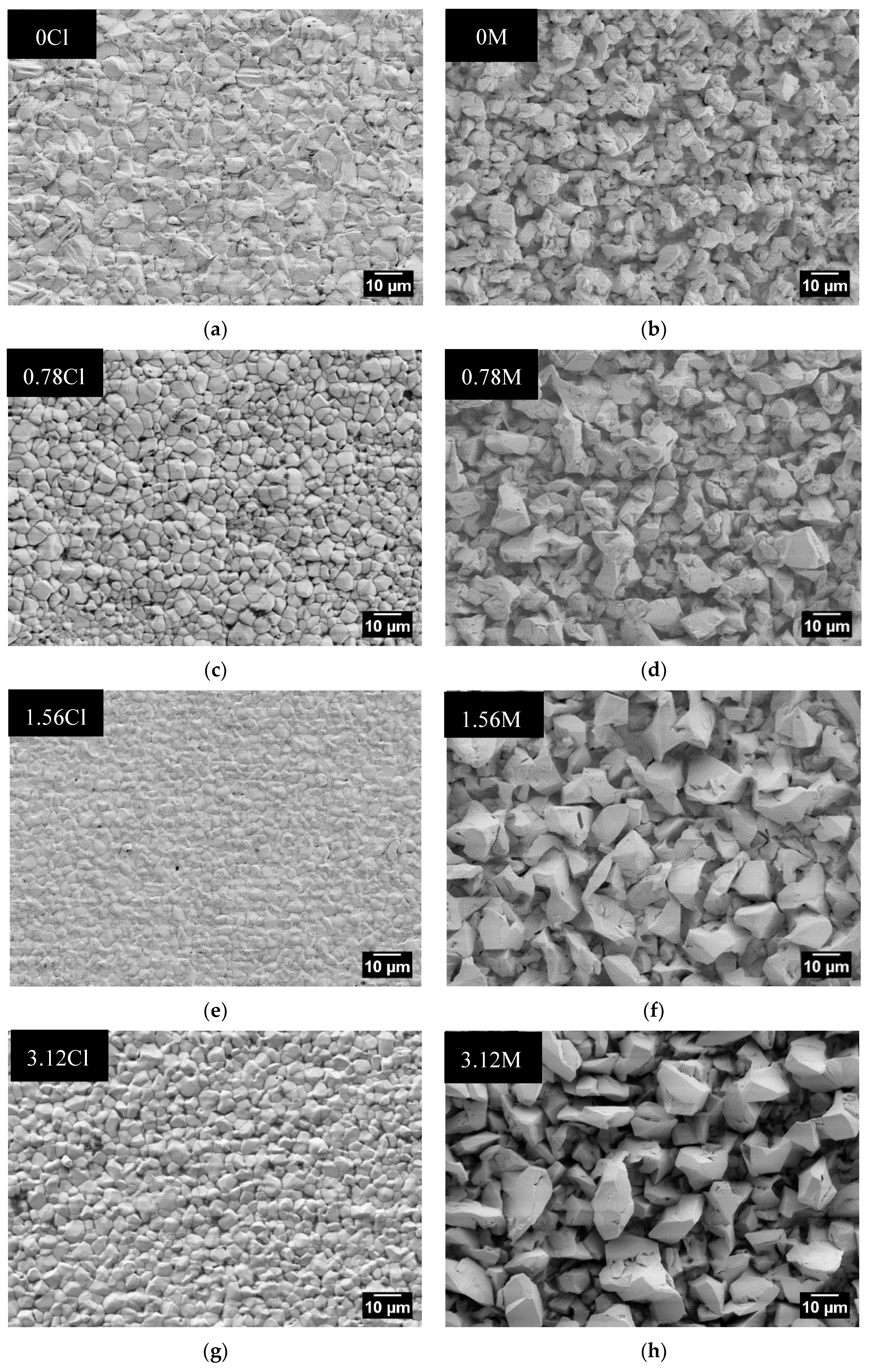
3.2. Surface Morphology
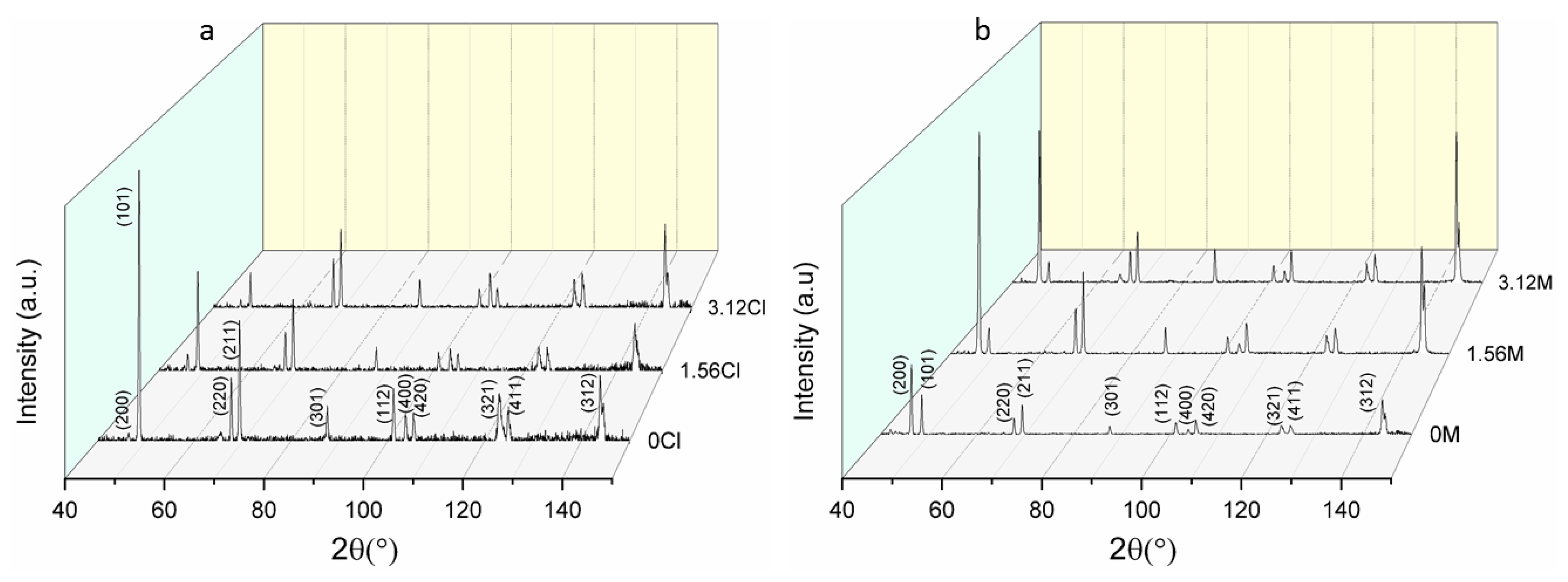
SEM micrographs of the as-plated surfaces were acquired to investigate the influence of the concentration of ABN on the surface morphology of the deposited tin coatings, (Figure 10). In the samples deposited from the chloride based electrolyte the addition of ABN leads to a change in the grain structure. The surface of the tin film deposited without ABN appears rough; grains are characterized by sharps edges with striation like substructure. In comparison, with the addition of ABN, the surface appears smooth and the grains turn to a more defined polygonised shape with distinguishable grain boundaries. This type of well-polygonised tin grain structure was reported in the case of satin bright tin chemistry [28,29]. Adding ABN, the grain size is also reduced. The measured average grain size (Table 5) shows that the smallest grains were obtained with an ABN concentration of 1.56 mg/L. The observed changes in the grain structure can be inferred to the inhibition provided with the addition of ABN. Inhibition is caused by the presence of substances different from the metallic ions of interests. These substances can be present at the surface of the electrode, and they hinder the cathodic process [30]. Different microstructures can be observed depending on the inhibition strength [31]. Similar grain refinement effects of the additive were found on Sn electrodeposited from chloride-based electrolyte [11].
Samples deposited from the MSA electrolyte show a different behavior. Independently of ABN addition the surface appears rough, with more complex grain structure. Grain boundaries are not clearly recognizable as in the case of the samples deposited from the chloride electrolyte with ABN. Besides that, striations as a grain substructure were detected (Figure 10). The increased roughness found in the samples can be related to the lower inhibition effects provided by ABN in the MSA electrolyte. As suggested by Fischer and Winand, coatings deposited with low-moderate inhibition are usually characterized by rough surfaces [30,31]. Furthermore, in contrast to the chloride electrolyte, addition of ABN resulted in the enlargement of the average grain size (Table 5).
The stirring of the plating solutions does not influence the overall surface morphology and the average grain size of the samples deposited from both electrolytes. A higher average grain size value was measured for some of the samples deposited from the stirred electrolytes and is in accordance with previous findings [32].

3.3. XRD Analysis

A comparison of the effect of ABN on the preferred crystal orientation of Sn films was conducted by XRD analysis. The analysis was focused on coatings deposited from both chloride and MSA electrolyte, from a stationary plating solution, and with three different ABN concentrations: 0, 1.56, and 3.12 mg/L. To avoid the detection of the substrate peaks, the analysis was performed with a grazing incidence configuration that allows the information depth of the measurements (limited to ~250 nm from the surface of the sample) to be reduced. Hence, a qualitative analysis of the texture of the samples is provided. 3D plots of the XRD spectra of tin coatings deposited from both chloride and MSA electrolytes are shown in Figure 11. From the analysis of the XRD spectra, all the Sn films deposited from both electrolytes can be considered as randomly-textured. The X-ray spectra of randomly-textured Sn films are commonly characterized by several minor peaks of high Miller-indexed planes [33], as in the case of the XRD spectra shown in Figure 11a,b. Such random-textured Sn films are obtained when the deposition is performed at relatively low current density resulting in a slower film growth rate. Applying high current density favors the deposition of Sn coatings with different texture, commonly along low Miller-indexed planes such as (200) or (220) planes [33]. Such coatings show weak or no diffraction peaks from higher Miller indexes planes, as also seen in previous studies on Sn deposited from chloride based [11,34] and MSA based electrolytes [28]. However, independently of the ABN addition in both electrolytes, the spectra shown in Figure 11 are characterized by the same number of peaks. In the X-ray spectra of the sample deposited from the chloride electrolyte with no ABN the (101) diffraction peak has the highest intensity. However, with increasing ABN concentration a constant decrease of the (101) intensity is observed (Figure 11a). The same trend was found for the samples deposited from the MSA electrolyte (Figure 11b) but less pronounced. This finding strengthens the hypothesis of ABN acting as an inhibitor in both chloride and MSA electrolytes, but to a different extent. The inhibition effect is more pronounced in the case of chloride based solution where ABN modifies the grain structure and strongly reduces the intensity of the (101) peak. The possible reason for the lower inhibition of ABN in the MSA electrolyte could be, that in the citrate-rich electrolyte there is a competition between the effect of the citrate, as a possible surfactant, which lowers the activation energy [27], and ABN as an inhibitor, which causes a rise in the activation energy [22]. Further experiments should be performed to confirm this assumption.

4. Discussion

In the present work, the influence of alkoxylated β-naphthol (ABN) on the tin electrodeposition from chloride based and MSA electrolyte was studied. ABN was introduced as a more stable alternative of the frequently used β-naphthol which can undergo oxidation under plating conditions. Moreover, ABN has a higher solubility due to the hydrophilic polymeric chain and introduces tensidic properties. Electrochemical characterization of both electrolytes with different ABN concentration was performed by polarization, Tafel measurements, and cyclic voltammetry on RDE and stationary electrodes.
In the case of chloride based solution, both polarization and Tafel measurements show a strong inhibition effect of ABN. The limiting current density decreases and H2 evolution is suppressed with the increase of ABN concentration. Results from the Tafel measurements showed a sharp decrease of the exchange current density j0 to 0.79 mA/cm2 at an ABN concentration of 0.78 mg/L indicating the blocking of the electrode surface by the ABN. Development of the current density over time during the jt transient experiments is also influenced by the presence of ABN. In the solution without ABN a slight increase of the current density was detected. On the other hand, the presence of 3.12 mg/L ABN caused an exponential decay of the current density until a constant value of –0.1 A/dm2 was reached after 100 s. This finding indicates that the surface electrode blocking reaches equilibrium after 100 s of electrodeposition. In the cyclic voltammograms there was no cross-over between the forward and backwards scan detected, indicating that there was no overpotential required for the Sn nucleation on Au to be started. Analyses of the stripping efficiency showed 10% decrease in the amount of reduced charge due to the presence of 3.12 mg/L ABN in the electrolyte. In the anodic regime, the formation of a passive layer was detected by CV.
In the case of MSA electrolyte, the inhibition effect of ABN is not as pronounced as in the case of the chloride based solution. For the studied ABN concentration range, polarization measurements and cyclic voltammetry on the MSA citrate-rich electrolyte showed no significant difference in the current density. In the citrate-free electrolyte a cathodic shift in the electrode polarization was detected due to the presence of ABN. This behavior was not dependent on the rotation speed of RDE, which indicates ABN adsorption on the cathode surface as a kinetically controlled process. On the other hand, polarization measurements of citrate-free electrolytes show that the presence of tin-citrate complexes has more influence on the electrolyte kinetics than the presence of ABN. Potentiostatic electrodeposition at –0.65 V showed pronounced surface roughness with increasing layer thickness. The combination of the citrate and 3.12 mg/L ABN in the electrolyte has a slight inhibition effect on the current density over electrodeposition time. This was confirmed by the results of the Tafel measurements where exchange current density j0 decreased from 51.29 to 25.12 mA/cm2 due to the presence of tri-sodium citrate. Slower electron transfer at the electrode interface causes a change in the deposit morphology. The tree-like dendritic structure turned to compact, non-dendritic layers when the citrate was added, which is consistent with the dendritic growth theory, which states that the creation of dendrites is favored by a high exchange current density. With the presence of the citrate in the electrolyte an increase in the stripping efficiency was observed. The exact role of the citrate in the MSA electrolyte is beyond the scope of this publication. A notable decrease of the exchange current density j0 from 25.12 to 15.14 mA/cm2 due to the presence of ABN was observed only at relatively high ABN concentration. This finding might indicate that the ABN acts as a blocker of the electrode active area in both chloride-based and MSA electrolyte, but in the case of MSA electrolyte higher ABN concentrations are needed.
The different influence of ABN in the two electrolytes was also confirmed by SEM micrographs and XRD measurements of the deposited tin films. ABN strongly modifies the grain structure of the Sn samples deposited from the chloride based plating solution: smooth surfaces were obtained with well distinguishable grains of polygonal shape. The average grain size was reduced, and the smallest grains were observed with an ABN concentration of 1.56 mg/L. A different trend was observed for the samples deposited from the MSA electrolyte. The grain structure appears just slightly modified and there is no grain refinement occurring with the ABN addition. The X-ray diffraction analysis showed no clear texture development in the samples deposited from both electrolytes with ABN addition. However, a constant decrease of the (101) intensity was observed with increasing concentration of ABN. The trend was clearly more pronounced in the case of the sample deposited from the chloride electrolyte.

Acknowledgments

This work was supported by the SELECTA (No. 642642) H2020-MSCA-ITN-2014 project.

Author Contributions

Simona P. Zajkoska and Wolfgang E. G. Hansal designed the electrochemical experiments; Simona P. Zajkoska performed the experiments and together with Rudolf Mann analyzed the data. Antonio Mulone and Uta Klement designed the structural characterization experiments; Antonio Mulone performed the experiments and analyzed the data. The overall work was supervised by Wolfgang E. G. Hansal, Uta Klement, and Wolfgang Kautek.

Conflicts of Interest

The authors declare no conflict of interest. The founding sponsors had no role in the design of the study; in the collection, analyses, or interpretation of data; in the writing of the manuscript, or in the decision to publish the results

References

  1. Lowenheim, F.A. Modern Electroplating, 3rd ed.; Electrochemical Society series; Wiley: New York, NY, USA, 1974. [Google Scholar]
  2. Rosenstein, C. Methane sulfonic acid as an electrolyte for tin, lead and tin-lead plating for electronics. Met. Finish. 1990, 19, 17–21. [Google Scholar]
  3. Walsh, F.C.; Low, C.T.J. A review of developments in the electrodeposition of tin. Surf. Coat. Technol. 2016, 288, 79–94. [Google Scholar] [CrossRef]
  4. Hansal, W.E.G.; Halmdienst, M.; Hansal, S.; Boussaboua, I.; Darchen, A. Influence of pulse plating parameters on morphology and hardness of pure tin deposit. Trans. Inst. Met. Finish. 2008, 86, 115–121. [Google Scholar] [CrossRef]
  5. Jordan, M. The Electrodeposition of Tin and Its Alloys; Eugen G. Leuze Publishers: Saulgau, Germany, 1995. [Google Scholar]
  6. Schlesinger, M.; Paunovic, M. Modern Electroplating, 5th ed.; John Wiley & Sons, Inc.: Hoboken, NJ, USA, 2010. [Google Scholar]
  7. Medvedev, G.I.; Makrushin, N.A. Electrodeposition of tin from sulfate electrolyte in the presence of syntanol, formaldehyde, and allyl alcohol. Russ. J. Appl. Chem. 2004, 77, 1781–1785. [Google Scholar] [CrossRef]
  8. Low, C.T.J.; Walsh, F.C. The stability of an acidic tin methanesulfonate electrolyte in the presence of a hydroquinone antioxidant. Electrochim. Acta 2008, 53, 5280–5286. [Google Scholar] [CrossRef]
  9. Low, C.T.J.; Walsh, F.C. Electrodeposition of tin, copper and tin–copper alloys from a methanesulfonic acid electrolyte containing a perfluorinated cationic surfactant. Surf. Coat. Technol. 2008, 202, 1339–1349. [Google Scholar] [CrossRef]
  10. Martyak, N.M.; Seefeldt, R. Additive-effects during plating in acid tin methanesulfonate electrolytes. Electrochim. Acta 2004, 49, 4303–4311. [Google Scholar] [CrossRef]
  11. Sekar, R.; Eagammai, C.; Jayakrishnan, S. Effect of additives on electrodeposition of tin and its structural and corrosion behaviour. J. Appl. Electrochem. 2010, 40, 49–57. [Google Scholar] [CrossRef]
  12. Sharma, A.; Bhattacharya, S.; Das, S.; Das, K. Influence of current density on surface morphology and properties of pulse plated tin films from citrate electrolyte. Appl. Surf. Sci. 2014, 290, 373–380. [Google Scholar] [CrossRef]
  13. Walsh, F.C.; Ponce de León, C. Versatile electrochemical coatings and surface layers from aqueous methanesulfonic acid. Surf. Coat. Technol. 2014, 259, 676–697. [Google Scholar] [CrossRef]
  14. Gernon, M.D.; Wu, M.; Buszta, T.; Janney, P. Environmental benefits of methanesulfonic acid. Green Chem. 1999, 1, 127–140. [Google Scholar] [CrossRef]
  15. Low, C.T.J.; Kerr, C.; Des Barker, B.; Smith, J.R.; Campbell, S.A.; Walsh, F.C. Electrochemistry of tin deposition from mixed sulphate and methanesulphonate electrolyte. Trans. Inst. Met. Finish. 2008, 86, 148–152. [Google Scholar] [CrossRef]
  16. Jordan, M. Electrodeposition of Tin and Its Alloys; Eugen G. Leuze Publishers: Saulgau, Germany, 1995. [Google Scholar]
  17. Panizza, M.; Cerisola, G. Influence of anode material on the electrochemical oxidation of 2-naphthol. Part 1. Cyclic voltammetry and potential step experiments. Electrochim. Acta 2003, 48, 3491–3497. [Google Scholar] [CrossRef]
  18. American Society for Testing and Materials, Committee E-4 on Metallography. ASTM Standard E112-12: Standard Test Methods for Determining Average Grain Size; ASTM International: Philadelphia, PA, USA, 2012; pp. 1–27. [Google Scholar]
  19. Barry, F.J.; Cunnane, V.J. Synergistic effects of organic additives on the discharge, nucleation and growth mechanisms of tin at polycrystalline copper electrodes. J. Electroanal. Chem. 2002, 537, 151–163. [Google Scholar] [CrossRef]
  20. Kapusta, S.D.; Hackerman, N. Annodic passivation of tin in slightly alkaline solution. Electrochim. Acta 1980, 25, 1625–1639. [Google Scholar] [CrossRef]
  21. Šeruga, M.; Metikoš-Hukovič, M. Passivation of tin in citrate buffer solution. Electrochim. Acta 1992, 334, 223–240. [Google Scholar] [CrossRef]
  22. Vračar, L.M.; Dražić, D.M. Adsorption and corrosion inhibitive properties of some organic molecules on iron electrode in sulfuric acid. Corros. Sci. 2002, 44, 1669–1680. [Google Scholar] [CrossRef]
  23. Meibuhr, S.; Yeager, E.; Kozawa, A.; Hovorka, F. The electrochemistry of tin. J. Electrochem. Soc. 1963, 110, 190–202. [Google Scholar] [CrossRef]
  24. Bengoa, L.N.; Tuckart, W.R.; Zabala, N.; Prieto, G.; Egli, W.A. Tin coatings electrodeposited from sulfonic acid-based electrolytes: Tribological behavior. J. Mater. Eng. Perform. 2015, 24, 2274–2281. [Google Scholar] [CrossRef]
  25. Han, C.; Liu, Q.; Ivey, D.G. Kinetics of Sn electrodeposition from Sn(II)-citrate solutions. Electrochim. Acta 2008, 53, 8332–8340. [Google Scholar] [CrossRef]
  26. Zhang, Y. Tin and tin alloys for lead-free solder. In Modern Electroplating, 5th ed.; John Wiley & Sons, Inc.: Hoboken, NJ, USA, 2011; pp. 139–204. [Google Scholar]
  27. Popov, K.I.; Nikolić, N.D. General theory of disperse metal electrodeposits formation. In Electrochemical Production of Metal Powders; Djokić, S.S., Ed.; Springer: New York, NY, USA; Heidelberg, Germany; Dordrecht, The Netherlands; London, UK, 2012; pp. 1–62. [Google Scholar]
  28. Zhang, Y.; Abys, J.A. A unique electroplating tin chemistry. Circuit World 1999, 25, 30–37. [Google Scholar] [CrossRef]
  29. Kakeshita, T.; Shimizu, K.; Kawanaka, R.; Hasegawa, T. Grain size effect of electro-plated tin coatings on whisker growth. J. Mater. Sci. 1982, 17, 2560–2566. [Google Scholar] [CrossRef]
  30. Fischer, H. Elektrolytische Abscheidung und Elektrokristallisation von Metallen; Springer: Berlin, Germany, 1954. [Google Scholar]
  31. Winand, R. Electrocrystallization—Theory and applications. Hydrometallurgy 1992, 29, 567–598. [Google Scholar] [CrossRef]
  32. Wen, S.; Szpunar, J.A. Nucleation and growth of tin on low carbon steel. Electrochim. Acta 2005, 50, 2393–2399. [Google Scholar] [CrossRef]
  33. Jagtap, P.; Kumar, P. Manipulating crystallographic texture of Sn coatings by optimization of electrodeposition process conditions to suppress growth of whiskers. J. Electron. Mater. 2015, 44, 1206–1219. [Google Scholar] [CrossRef]
  34. He, A.; Liu, Q.; Ivey, D.G. Electrodeposition of tin: A simple approach. J. Mater. Sci. Mater. Electron. 2008, 19, 553–562. [Google Scholar] [CrossRef]
Figure 1. Two step oxidation process of β-naphthol [16].
Coatings 08 00079 g001
Figure 2. Alkoxylated β-naphthol (ABN) structural equation.
Coatings 08 00079 g002
Figure 3. Polarization curves measured with the rotating disk electrode (RDE) in the chloride based electrolyte: (a) convection kept constant at 256 rpm and varying the ABN content. Cathodic current and H2 evolution is suppressed with the increased additive concentration (b) with the optimum concentration of ABN 1.56 mg/L, varying the electrolyte convection. Introducing of the convection causes an increase in the limiting current densities.
Coatings 08 00079 g003aCoatings 08 00079 g003b
Figure 4. Cyclic voltammograms in the chloride electrolyte showing the creation of the oxide layer (peak I and II) and bulk Sn dissolution (peak III) for: (a) different ABN concentration. With the increased additive concentration both oxide and Sn layer are hindered, (b) for two different cathodic return points −0.8 and −1 V. At the higher cathodic return potential, more Sn is deposited while the oxide layer remains the same as for the −0.8 V.
Coatings 08 00079 g004
Figure 5. Current density transients in chloride based electrolyte at −0.8 V. The ABN inhibition process reaches equilibrium after 100 s of deposition.
Coatings 08 00079 g005
Figure 6. Polarization curves measured with the rotating disk electrode (RDE) in the MSA electrolyte: (a) convection kept constant at 256 rpm and varying the ABN content. The addition of ABN has no visible influence on the cathodic current. (b) with the optimum concentration of ABN 1.56 mg/L for the chloride based electrolyte and varying the electrolyte convection by increasing the electrode rotation. Similarly, to the chloride based electrolyte, current density is increased when the convection of the electrolyte is introduced. However, the limiting current density plateau is no longer visible.
Coatings 08 00079 g006
Figure 7. Role of the ABN additive in the MSA electrolyte without complexing agent and the MSA electrolyte containing 100 g/L tri-sodium citrate. Inhibition effect of the ABN in the citrate-rich electrolyte is covered by the presence of tin-citrate complexes.
Coatings 08 00079 g007
Figure 8. Cyclic voltammograms in MSA electrolyte for different ABN concentrations.
Coatings 08 00079 g008
Figure 9. Current density transients in MSA electrolyte at −0.65V. Horizontal line marks current density of −1.5 A/dm2 at which dendritic layers from citrate and ABN free electrolyte were deposited.
Coatings 08 00079 g009
Figure 10. Surface topography of the samples deposited from non-stirred solution with increasing ABN concentration: 0, 0.78, 1.56, 3.12 mg/L, from chloride based electrolyte in (a,c,e,g), and from MSA electrolyte (b,d,f,h).
Coatings 08 00079 g010
Figure 11. (a) 3D X-ray diffraction profile of the Sn samples deposited from stationary chloride electrolyte with increasing ABN concentration (b) and of the Sn samples deposited from non-stirred MSA electrolyte.
Coatings 08 00079 g011
Table 1. Composition of the chloride based and methane sulfonic acid (MSA) electrolytes.
Electrolyte CompositionChloride (g/L)MSA (g/L)
SnCl2·2H2O (abcr, Karlsruhe, Germany)25
Na3C6H5O7 (Sigma Aldrich, Seelze, Germany)80100
KNaC4H4O6·6H2O (Carl Roth, Karlsruhe, Germany)25
(NH4)2SO4 (Sigma Aldrich, Seelze, Germany)60
MSA (70%) (Carl Roth, Karlsruhe, Germany)157 mL/L
SnMSA (300 g/L Sn2+) (Atotech, Berlin, Germany)166 mL/L
Table 2. Influence of the alkoxylated β-naphthol (ABN) concentration on the kinetics parameters in the chloride electrolyte.
ABN Concentration (mg/L)J0 (mA/cm2)Tafel Slope Cathodic (mV)Tafel Slope Anodic (mV)Uoc (mV)
07.08−0.00070.0152−734.1
0.53.31−0.00220.0139−734.6
0.780.79−0.00420.0185−722.9
1.171.12−0.0040.0161−720.6
1.561.12−0.00390.0179−723.8
2.50.89−0.00350.0185−723.8
3.120.71−0.00410.0217−720.8
4.370.65−0.00450.0201−718.8
Table 3. Influence of the ABN concentration on the kinetic parameters in the MSA electrolyte.
ABN Concentration (mg/L)J0 (mA/cm2)Tafel Slope cathodic (mV)Tafel Slope Anodic (mV)Uoc (mV)
025.12−0.00340.0044−440.75
0.522.39−0.00330.0039−443.56
0.7823.99−0.0037−0.0037−456.25
1.1723.99−0.00340.0036−460.34
1.5623.99−0.00300.0030−458.75
2.522.910.00330.0033−464.06
3.1220.89−0.00380.0037−460.58
4.3715.14−0.00380.0035−462.17
Table 4. Influence of the ABN concentration on the kinetics parameters in the MSA citrate-free electrolyte.
ABN Concentration (mg/L)j0 (mA/cm2)Tafel Slope Cathodic (mV)Tafel Slope Anodic (mV)Uoc (mV)
051.29–0.00360.0044–457.66
1.5652.48–0.00370.0038–466.81
3.1240.74–0.00360.0034–471.69
Table 5. Average grain size (l) with standard deviation (S.D.) for the samples deposited from chloride based and MSA electrolytes.
Chloride ElectrolyteMSA Electrolyte
Sample CodeFrom Stirred SolutionFrom Non-Stirred SolutionSample CodeFrom Stirred SolutionFrom Non-Stirred Solution
l ± S.D. (µm)l ± S.D. (µm)l ± S.D. (µm)l ± S.D. (µm)
0Cl6.1 ± 0.46.1 ± 0.60M7.9 ± 17.9 ± 0.9
0.78Cl4 ± 0.33.8 ± 0.30.78M8.2 ± 0.98.3 ± 0.6
1.56Cl2.4 ± 0.32.3 ± 0.21.56M11 ± 1.69.2 ± 1.3
3.12Cl3.9 ± 0.23.9 ± 0.43.12M11.8 ± 1.79.7 ± 1.8

