1. Introduction
Metallic orthodontic appliances, such as brackets and archwires, typically show superior properties [
1] and provide many clinical advantages, such as low frictional resistance and good bending performance as orthodontic archwires. They have been widely used in clinical orthodontics, although they have esthetic limitations compared to other orthodontic appliances made from ceramics and plastics. Another disadvantage of metallic orthodontic appliances is corrosion in the oral environment [
2,
3], because the release of metallic ions, such as nickel (Ni) and chromium (Cr), may cause an allergic reaction during orthodontic treatment [
4,
5,
6].
The frictional force between the bracket and archwire (resistance to sliding) during tooth movement is a primary issue in orthodontics [
7,
8]. If the frictional force can be decreased, then the efficiency of the tooth movement can be improved. To improve the frictional characteristics and corrosion resistance, various surface modification techniques, such as diamond-like carbon (DLC) coating [
9,
10,
11,
12], plasma immersion ion implantation [
7,
13,
14] and bioactive glass coating [
15], have been investigated.
In recent years, DLC coating has become the subject of considerable research interest due to its bioinertness, extreme hardness, low friction coefficient and high wear resistance [
16]. This technique has attracted significant attention for biomedical applications, such as artificial joints, cardiac stents and orthodontic archwires [
17]. Concerning orthodontic applications, experimental DLC-coated orthodontic wires have been studied by several research groups [
9,
10,
11,
12,
18,
19,
20]. One study reported that DLC layers protect against the diffusion of Ni and its release at the surface of Ni–Ti archwires and that these coatings are noncytotoxic in corrosive environments [
18]. Other studies have investigated the effect of DLC coatings on the friction of orthodontic wires and found that DLC-coated wires produced less frictional resistance than non-coated wires [
9,
10,
11,
12,
18,
19,
20]. The properties of a DLC coating depend on the hydrogen content,
sp2/
sp3 ratio and presence of doping elements [
21,
22]. The properties of DLC-coated orthodontic materials are not well understood, and limited information is available regarding the hydrogen content and
sp2/
sp3 ratio of DLC-deposited surfaces.
First, we deposited a DLC film onto orthodontic stainless steels using two different parameters and characterized the DLC films to determine their hydrogen content, sp2/sp3 ratio and mechanical properties. The bending and frictional properties of the DLC-coated orthodontic stainless steels were also investigated.
2. Materials and Methods
2.1. Materials
Mechanically-polished stainless steel disk specimens (diameter: 14 mm; thickness: 2 mm; Nogata Denki Kogyo, Tokyo, Japan) and as-received stainless steel orthodontic wires with cross-sectional dimensions of 0.017 × 0.025 in2 (stainless steel archwire; 3M Unitek, Monrovia, CA, USA) were purchased and subjected to DLC coating. These stainless steels were confirmed to be Type 304 austenitic stainless steel (ISO No. 4301-304-00-I) by X-ray fluorescence analysis. As-received, preadjusted stainless steel orthodontic brackets (Mini Uni-Twin; 3M Unitek) for the upper canine teeth were used for friction tests. Non-coated specimens served as a control.
2.2. DLC Coating Procedure
DLC films were deposited onto stainless steel disks and wires using a plasma-based ion implantation/deposition (PBIID) method after the specimens were cleaned ultrasonically with acetone and alcohol. A custom-made jig was used to hold the specimens in the PBIID equipment (PEKURIS-HI; Kurita Seisakusho, Kyoto, Japan). To obtain DLC films with different compositions, two different parameters for target voltage, gas atmosphere and deposition time were used; these are listed in
Table 1. All deposition processes were carried out at a pressure of 1.33 × 10
−3 Pa.
2.3. Phase Identification by X-ray Diffraction and Scanning Electron Microscopy of the Coating
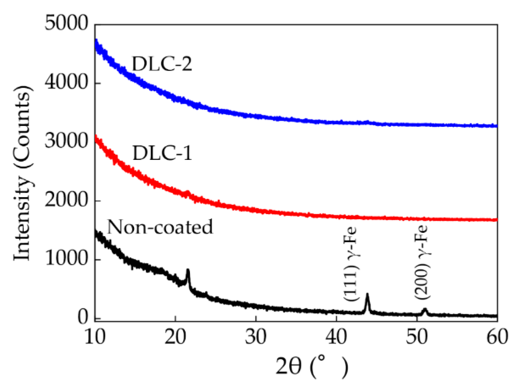
Wire specimens were cut into segments (length: 1 cm) using a water-cooled diamond saw (Isomet; Buehler, Lake Bluff, IL, USA). The segments were then placed side-by-side on the sample holder to yield ca. 1 × 1 cm2 specimens. Representative surfaces of the control and DLC-coated wire specimens were analyzed using XRD (Rint-2500; Rigaku, Tokyo, Japan) via a parallel-beam method using Cu–Kα radiation (40 kV; tube current: 100 mA) over 2θ ranging from 10°–60° at a step size of 0.02° and a scan speed of 0.25° min−1. The XRD patterns were obtained at 25 °C and analyzed for phase identification and quantification using PDXL2 software (Rigaku) based on the International Center for Diffraction Data (ICDD) database.
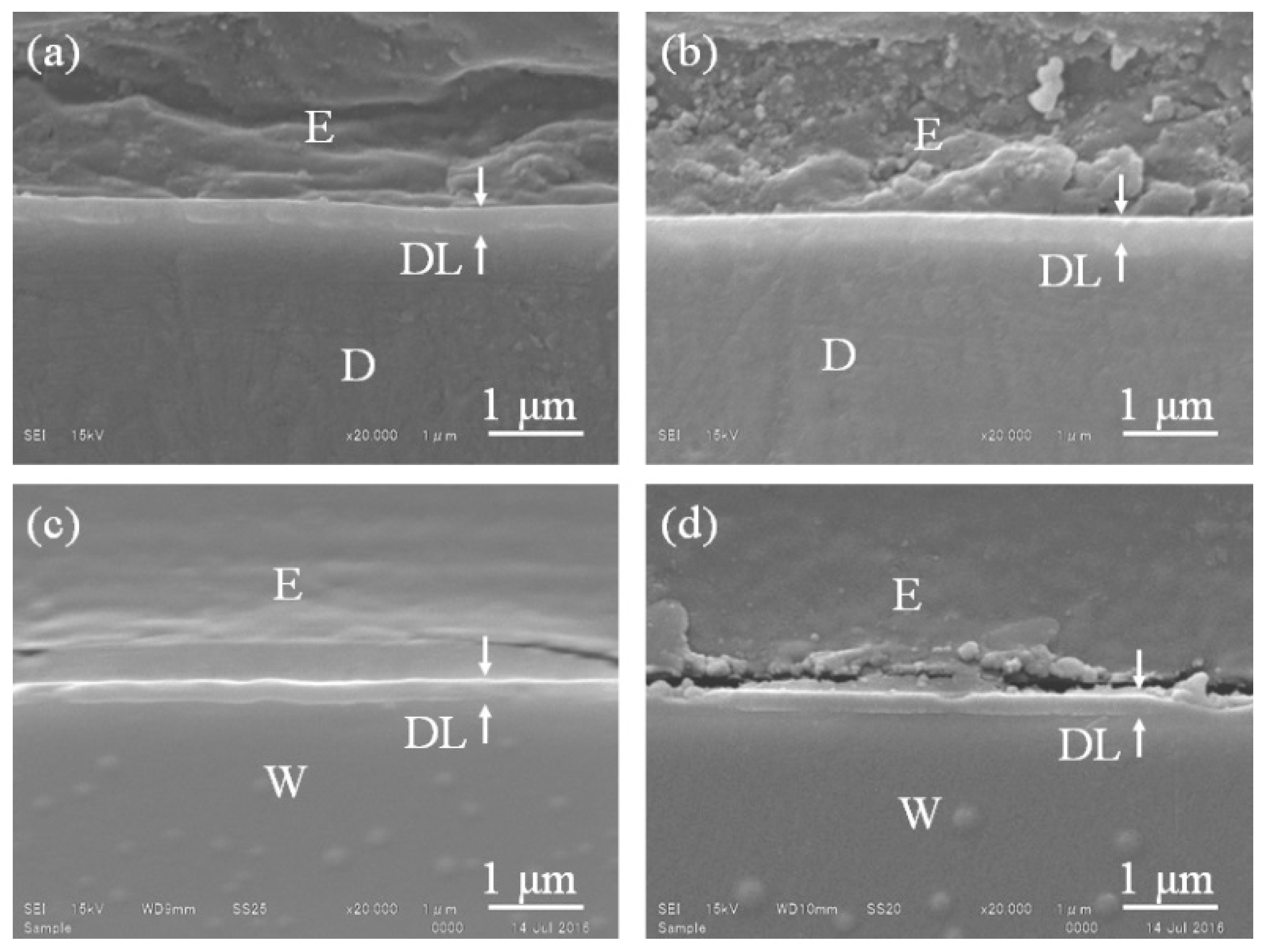
To observe the DLC-coated layers on a cross-sectioned surface, a wire specimen was encapsulated in an epoxy resin (Epofix; Struers, Copenhagen, Denmark) cross-sectioned with a slow-speed, water-cooled diamond saw (Isomet; Buehler) and then ground and polished using a series of silicon carbide abrasive papers and a final slurry of 0.05-μm alumina particles. All specimens were sputter-coated with pure gold for SEM evaluation (JSM-6610LA; JEOL, Tokyo, Japan); the SEM operated at 15 kV.
2.4. Compositional Characterization of the Coating by High-Resolution Elastic Recoil Analysis and Microscale X-ray Photoelectron Spectroscopy
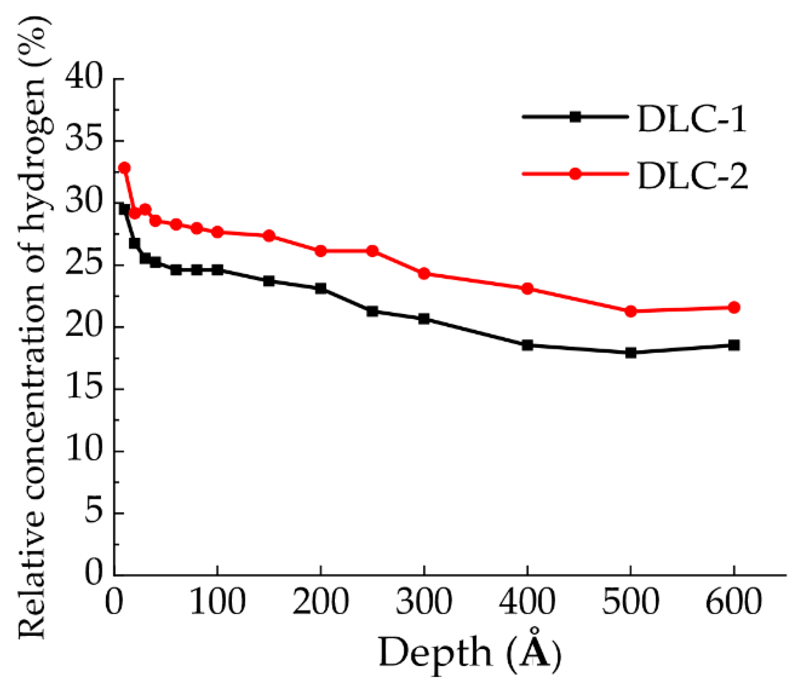
An elastic recoil detection analyzer (ERDA; HRBS1000; Kobelco, Hyogo, Japan) was used for depth profiling of the hydrogen content of DLC-coated disk specimens. The ion type, acceleration voltage, incident angle and scattering angle were N+, 500 kV, 67.5 and 45.6°, respectively. The main chamber was maintained at a pressure less than 1 × 10⁻⁵ Pa during the measurements. A multi-channel plate was used as the detector in this study. A beam of 500 keV N+ ions was irradiated against the surface of the specimens, and hydrogen ions recoiled at 45.6° were measured by the 90° sector-type magnetic spectrometer. To reject the scattered N+ ions, a Mylar foil was set in front of a multi-channel plate detector. The energy of hydrogen ions recoiled from the surface region of the implants was ca. 61 keV. Amorphous carbon materials with 20 at.% hydrogen were used as the standard sample. The standard sample was also measured under the same measurement conditions. The hydrogen contents of the specimens relative to carbon were compared with that of the standard sample. This enabled the depth profile of the contents to be calculated because the change in energy of the hydrogen ions corresponds to their depth from the surface.
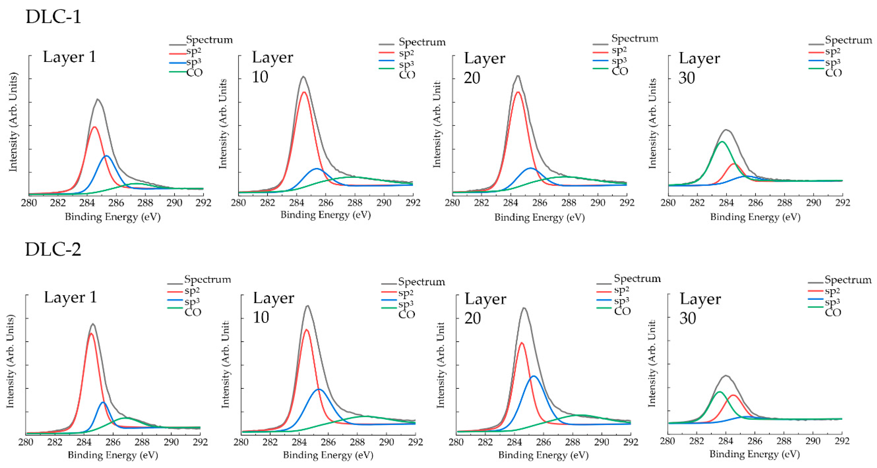
The surface and in-depth composition of the control and DLC-coated disk specimens were analyzed by micro-XPS (Quantera II; Ulvac-Phi, Kanagawa, Japan) using Al Kα radiation with a 25-W beam power. The pressure of the main chamber was maintained at less than 1 × 10⁻⁶ Pa. Measurements on a 100 μm2 area of the disk specimens were conducted from 0–1100 eV at a step size of 0.2 eV. The counting time was 20 ms for each step, and the number of sweeps was 5, i.e., the total counting time was 100 ms at each step. Argon-ion sputtering was used for depth profiling measurements. The ion sputtering area was 2 × 2 mm2, and the measurements were taken at the center of the area. The sputtering rate of a SiO2 layer under the same conditions was 13 nm min−1. The sp2 (for graphite) and sp3 (for diamond) contents were determined using the software bundled with the XPS apparatus.
2.5. Mechanical Properties of the Coating from Nanoindentation and Three-Point Bending Testing
The external surfaces of DLC-coated wire specimens were examined with a nanoindentation apparatus (ENT-1100a; Elionix, Tokyo, Japan). The specimens were fixed to the specimen stage with adhesive resin (Superbond Orthomite; Sun Medical, Shiga, Japan). Nanoindentation testing was carried out at 28 °C using a Berkovich indenter for depth analyses at 20 and 70 nm (
n = 10). Linear extrapolation methods (according to the ISO Standard 14577 [
23]) were applied to the unloading curve between 95% and 70% of the maximum test force to calculate the elastic modulus. The hardness and elastic modulus of the wire specimen surfaces were calculated using the software bundled with the nanoindentation apparatus.
2.6. Evaluation of the Elastic Modulus of the DLC-Coated Wires by the Three-Point Bending Testing
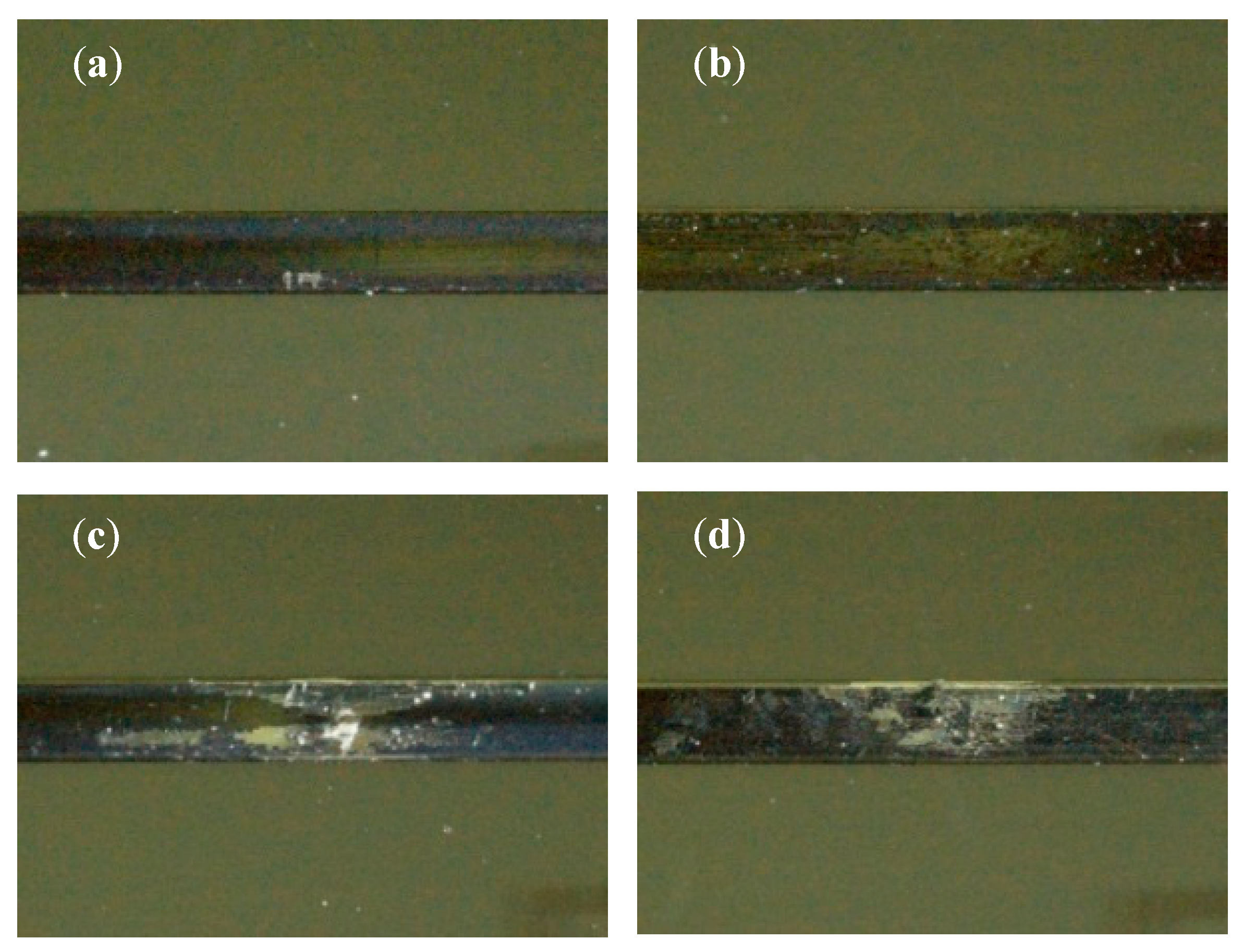
A three-point bending test was carried out for non-coated and DLC-coated wires (n = 10). A 12-mm span was chosen for the wire segments in accordance with the ANSI/ADA Specification No. 32. All samples were loaded following the same protocol on a universal testing machine equipped with a 20 N load cell (EZ Test; Shimadzu, Kyoto, Japan) at room temperature (25 °C). Each wire was first loaded to a deflection of 1.0 or 1.5 mm and then unloaded at a rate of 0.5 mm min−1. Following a three-point bending test, a specimen was inspected with a stereoscopic microscope (SMZ1500; Nikon, Tokyo, Japan) to observe the detachment of the DLC layers.
2.7. Frictional Properties Measured by the Progressive Load Scratch Test and Drawing Friction Test
A microtribometer (CETR-UMT-2; Bruker, Billerica, MA, USA) was used to characterize the frictional properties of each disk specimen by the progressive-load scratch test. A diamond stylus having a 12.5-μm tip radius was moved 5 mm over a specimen surface with linearly increasing normal load (0.5–20 gf) at a constant speed of 0.016 mm s−1, and the value of the friction coefficient (tangential force) was obtained (n = 5). The initial frictional force, average frictional force during the first 0.5-mm scratch and total frictional force and average frictional force during the entire 5-mm scratch were calculated. After the scratch test, each specimen was inspected with a stereoscopic microscope (SMZ1500; Nikon, Tokyo, Japan) to determine the distance for detachment.
The forces generated with each wire/bracket combination were measured under dry and wet (in artificial saliva) conditions at room temperature (25 °C) using a custom-fabricated drawing-friction testing device attached to a universal testing machine (EZ Test; Shimadzu, Kyoto, Japan) [
9]. Each bracket was bonded to a stainless steel plate with a non-filled adhesive resin (Superbond; Sun Medical, Shiga, Japan), and a bracket-mounting device provided 10° angular positioning for the bracket. The stainless steel plate with the bracket was attached to a friction-testing device. A 5-cm wire segment was then bound to the bracket using an elastic ligature (Alastik Easy-To-Tie Ligatures, 3M Unitek). The upper end of the wire was fixed to a grip attached to the load cell, and the lower end of the wire was fixed to a 150-g weight. Each wire was drawn through the bracket at a crosshead speed of 10 mm min
−1 for a distance of 5 mm. The X axis was recorded for wire movement and the Y axis for the force. In the present study, the static frictional force was determined at the initial peak of movement, and the kinetic frictional force was calculated by averaging force values after the static friction peak [
7,
8]. The sample size for each condition was 10 (
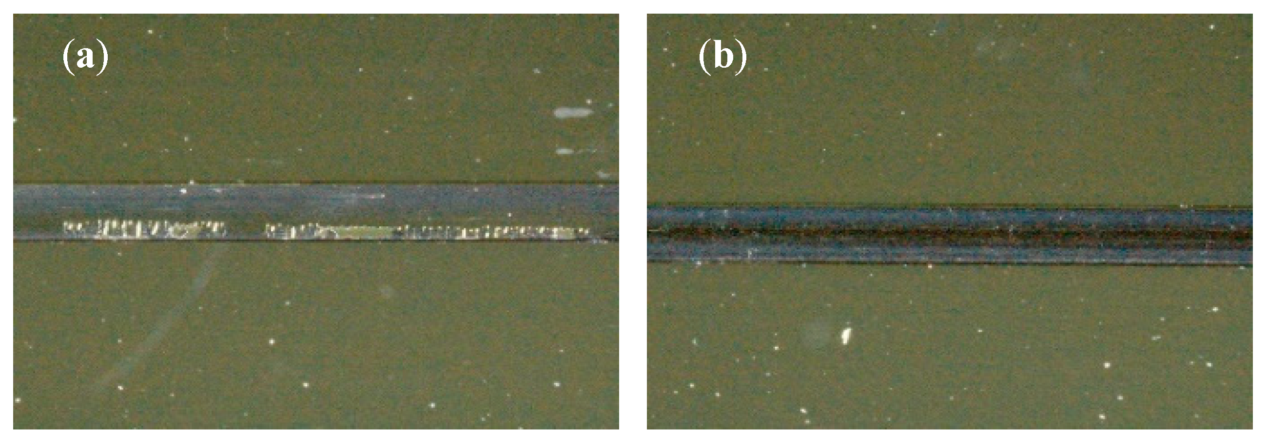
n = 10). After the drawing-friction test, a specimen was inspected with a stereoscopic microscope (SMZ1500; Nikon) to observe the detachment of the DLC layers.
2.8. Statistical Analyses
Statistical analyses were performed using SPSS Statistics software (ver. 23J for Windows; IBM, Armonk, NY, USA). The mean frictional forces, along with the standard deviation, were analyzed by two-way analysis of variance (ANOVA). The two factors were the coating procedure (non-coating, DLC-1, DLC-2) and test environment (dry, wet). Additionally, the mean hardness, elastic modulus and frictional force were compared using one-way ANOVA, followed by Tukey’s or Games–Howell tests. The mean distance for detachment in the progressive-load scratch test was compared using Welch’s t-test. For all statistical tests, significance was predetermined at p < 0.05.
4. Discussion
In this study, ca. 300 nm-thick DLC layers were deposited on orthodontic stainless steels. The coatings were amorphous, which was consistent with previous findings [
24]. The type of DLC can be identified using a ternary phase diagram [
16]. This diagram shows the fraction of carbon sites that have
sp2 (graphite-like) bonding,
sp3 (diamond-like) bonding or bonding with hydrogen. Quantitative analysis of
sp2 and
sp3 bonding in a DLC can be performed by XPS analysis [
25,
26]. In the present study, the DLC-1 had a higher
sp2/
sp3 ratio (0.343) at the external surface region (ca. 13 nm deep), while the DLC-2 had a lower
sp2/
sp3 ratio (0.181) at the external surface region. This indicated that the external surface of the DLC-1 had a more diamond-rich structure than the DLC-2. After four more layers had been sputtered, the
sp2/
sp3 ratio (measured at a depth of ca. 65 nm) was similar for DLC-1 (0.235) and DLC-2 (0.283). Furthermore, this trend changed after 10 layers were sputtered (measured at a depth of ca. 130 nm) when the DLC-1 displayed a lower
sp2/
sp3 ratio (0.201), although the DLC-2 had a higher
sp2/
sp3 ratio (0.343). This indicated that the inner surface of the DLC-2 had a more diamond-rich structure than the DLC-1. Nanoindentation testing suggested that the DLC-1 had better mechanical properties than the DLC-2 at the external surface region, while the DLC-2 seemed to have better mechanical properties than the DLC-1 at the inner surface region. These findings are supported by the
sp2/
sp3 ratios measured at the different depths in this study, because the diamond structure is harder than the graphite structure [
16]. Quantitative analysis of hydrogen in a DLC can be performed by elastic recoil measurements [
27]. Using this technique, the average hydrogen content of DLC-2 (27%) was slightly higher than that of DLC-1 (23%). A higher hydrogen content of a DLC coating layer can lead to a higher hardness and elastic modulus [
28,
29], which may influence wear rate and frictional properties.
Most DLC films are harder than metallic materials. DLC coatings using PBIID methods provide hardnesses ranging from 6 to 20 GPa, depending on the deposition conditions [
16,
18,
19]. The hardness of the DLC layers determined by nanoindentation testing in this study ranged from 9.18 to 9.69 GPa (when measured at a depth of ca. 70 nm), which is much higher than the 6.4 GPa measured by nanoindentation testing under the 20-mN load of the as-received stainless steel orthodontic wire. Additionally, the DLC layers showed a much higher elastic modulus compared with non-coated stainless steel orthodontic wires [
30], which should influence the elastic modulus of whole archwires. This is supported by the three-point bending results of the present study. The DLC-coated wire exhibited a significantly higher elastic modulus (by 6%–11% as measured by the three-point bending test) than the non-coated wire. Fortunately, variation of this level may not influence clinical orthodontic tooth movement because a wide range of initial orthodontic forces (18–1500 gf) has been proposed as the optimum force for orthodontic tooth movement, and evidence is lacking regarding the optimal force level [
31]. Three-point bending at a span of 1.0 mm caused the coating layer to detach from the inner core for only the DLC-1 wire. None of the coatings of the DLC-2 wires were damaged, probably because the DLC-2 coating had better mechanical properties and adhesion.
Several recent studies of DLC coating reported excellent frictional properties [
9,
10,
11,
12,
18,
19,
20], fine cell growth with non-cytotoxicity [
18], less bacterial adhesion [
32] and inhibited biofilm formation on the metal with DLC coatings [
33]. Similarly, the progressive-load scratch test in the present study revealed that both DLC-coated disk specimens (DLC-1, DLC-2) displayed significantly lower frictional forces than the non-coated disk specimens. One explanation for this behavior is that the DLC layer, with higher hardness due to the diamond-rich structure, produced lower frictional forces because of a lower wear rate [
16]. Additionally, the hydrogen content might have contributed to lower friction under the dry condition because of the elimination of free σ-bonds on the surface [
12]. However, only DLC-2 produced significantly lower frictional force than the non-coated case in the drawing-friction test with a 10° positioning of the bracket under the wet condition. This was attributed to partial rupture of the coating of DLC-1, causing increasing wire-binding at the edge of the bracket [
34], thereby increasing the frictional force. Crack initiation and ruptured coating regions were not observed for DLC-2, which suggested that the DLC-2 coating had good flexibility as a functionally-graded material with outstanding adhesion to the orthodontic stainless steel substrate. Additionally, the hydrogen content of the DLC layers might be important under the wet condition. Water molecules might react with a hydrogenated DLC coating to form oxygen-containing hydrophilic groups on the surface that could provide lubrication for the sliding counter surface [
21,
22]. Another possibility is that hydrogen-terminated surfaces of a hydrogenated DLC coating may interact through weak van der Waals forces [
16,
22].
The improved frictional properties demonstrated in this work for the DLC-coated samples suggest that tooth movement by sliding mechanics using DLC-coated stainless steel wire may be superior to that using conventional stainless steel wire. However, further randomized controlled trials are required to assess the clinical efficacy.


