Superconducting Niobium Coatings Deposited on Spherical Substrates in Molten Salts


Tananaev Institute of Chemistry, Kola Science Centre, Russian Academy of Sciences, 184209 Apatity, Russia
*
Author to whom correspondence should be addressed.
Coatings 2018, 8(6), 213; https://doi.org/10.3390/coatings8060213
Submission received: 16 May 2018
/
Accepted: 1 June 2018
/
Published: 4 June 2018
(This article belongs to the Special Issue Thin Films and Patterned Structures by Electrochemical Methods)
Abstract
:The interaction of substrates from ceramics, beryllium, and carbopyroceram with the electrolyte for the electrodeposition of niobium coatings was investigated. The corrosion resistance of spherical ceramic and beryllium samples with the protective molybdenum films obtained by magnetron sputtering was studied. The exfoliation of molybdenum film from ceramics and beryllium samples was observed after the experiments due to the interaction of substrates with the melt. It was found that the carbopyroceram did not corrode in the niobium containing melt and this material was chosen as the substrate for the electrodeposition of superconducting niobium coatings. The influence of the oxide ions on the electrochemical behavior of niobium complexes in the NaCl–KCl–NaF–K2NbF7 melt was studied. A special form of the cathode was constructed for the electrodeposition of niobium coatings on spherically shaped substrates. Electrodeposition of the niobium coatings on spheres 10 mm in diameter manufactured from carbopyroceram was carried out at 750 °C with the cathodic current density of 5 × 10⁻³–2 × 10⁻² A·cm−2 and the electrolysis time of 8–12 h. Influence of the cathodic current density on the microstructure of niobium coatings was studied. The roughness, nonsphericity, and superconductive properties of niobium coatings were determined.
1. Introduction
Niobium in the form of thin films and coatings are used in high-tech cryogenic devices using the phenomenon of superconductivity [1,2,3,4].
Niobium coatings can be obtained by different methods: plasma detonation, sputtering, and deposition from the gas phase. For the moment, these methods do not allow the production of coatings on large-sized articles and have difficulties with deposition coatings with even distribution over the article surface.
The authors of [5,6,7,8] performed a qualitative analysis of the efficiency of coating deposition across different methods. The respective criteria were divided into three groups: possibilities of obtaining and controlling the process parameters, providing quality parameters, and technological and cost indices. The performed estimation of the efficiency of the deposition methods according to the accepted criteria demonstrated that one of the most promising methods is electrolysis in molten salts, allowing for uniform coatings on articles with a complex configuration to be obtained.
Previously [2], electrolytic niobium superconducting (SC) coatings on the refractory metals (Nb, Mo, W) substrates and on the non-ferrous metal substrates (Ti, Ni, Cu) were produced and investigated. However, this list is not comprehensive for the manufacture of superconducting cryogenic devices based on niobium coatings and films. For example, the base material for the magnetic rotor of the SC-cryogenic gyroscope required a substrate that combined a low density with high strength.
Ceramics, beryllium, and carbopyroceram (CPC) are potential materials for rotor substrates. The advantages and lack of each material were discussed in detail in [9].
According to [9], carbopyroceram as the rotor substrate material was chosen due to high corrosion resistance in the electrolyte for niobium deposition. Carbopyroceram, like a pyrocarbon, is a material obtained by the combined pyrolysis of hydrocarbons with boron halides. It is an isotropic material. Carbopyroceram is a consolidated nanomaterial with the average crystallite sizes of turbostratic carbon at 10 by 10 nm. At this size of dispersed particle (less than a certain critical size), intense agglomeration of particles is achieved due to a high concentration of uncompensated bonds of the carbon atoms outer layers, and also through the formation of strong bonds with heteroatoms introduced into the initial reagents.
Oxygen is an impurity that most seriously affects the mechanical and SC properties of niobium metal. According to [10,11], a mere increase of oxygen content from 0.024 to 3.5 at.% boosts the niobium hardness from 64 to 380 kg·mm−2, and decreases the critical temperature from 9.23 to 6.13 K. There are several ways by which oxygen can penetrate into the melt during the niobium electrolysis: from the anode material, from the residual moisture in electrolyte salts, and from fluoride salts contaminated by oxofluorides during their production and drying due to the insufficient gas tightness of the electrolyzer, from the neutral gas containing moisture and oxygen, etc. In all cases, it creates oxofluoride complexes such as NbOF63− in the bath.
Hence, it is the necessity to understand the electrochemical behavior of niobium oxofluoride complexes in NaCl–KCl–NaF–K2NbF7 melt. When discharging, niobium oxofluoride complexes may form oxygen–niobium solid solutions, and also niobium oxides and oxofluoride compounds with oxidation states of less than +5.
The goal of the present study was the electrodeposition of smooth superconducting niobium coatings on spherical substrates in molten salts.
2. Materials and Methods
2.1. Chemicals and Preparation of Salts
In this work, we used a chloride–fluoride electrolyte with the composition NaCl–KCl–NaF (10 wt %)–K2NbF7 (8 wt %).
The salt mixture prepared by the outlined procedure [12,13] was placed in a niobium-lined molybdenum crucible and transferred to the retort of the electrolytic cell. The design of the cell was described in detail in [14]. The electrolyte in the cell retort was evacuated to a residual pressure of 3 Pa at 120 °C, the cell was filled by high-purity grade argon, which was passed through the LLC (limited liability company) “SOLO” SOG-4 gas purification system and the electrolyte was melted.
Note that upon contact of the niobium anode with the melt during the 2 h, the metal–salt reaction takes place in the melt [15]:
4Nb(V) + Nb ↔ 5Nb(IV)
The equilibrium of this reaction was completely shifted to the right side, which was confirmed by a 1.25-fold increase of the niobium concentration in the melt.
2.2. Electrochemical Studies and Characterization
Linear sweep voltammetry and cyclic voltammetry were employed using a VoltaLab-40 potentiostat with complementarily packaged software “VoltaMaster 4” (Version 6). The potential scan rate (ν) was varied between 5 × 10⁻³ and 5.0 V·s−1. Experiments were carried out in the temperature range of 700–850 °C. The voltammetric curves were recorded on a glassy-carbon and platinum electrode (diameter of 2 mm and 1 mm, respectively) relative to a quasi-reference electrode from glassy carbon of the SU-2000 brand. A glassy-carbon SU-2000 crucible served as both the container for the melt and the auxiliary electrode.
To identify the cathodic products, a Shimadzu XRD-6000 diffractometer (Shimadzu, Kyoto, Japan) was used. The concentration of metallic impurities in electrolytic niobium was determined by spectral quantitative analysis Iskroline 300 (Iskroline, St.-Petersburg, Russia) and after dissolution of the niobium coating by a Perkin-Elmer AAS 4100—ZL atomic absorption spectrometer (Perkin-Elmer, Norfolk, VA, USA). The gases in niobium were detected by a Gas Chromatograph-Mass Spectrometer GCMS-QP2010 Ultra Shimadzu (Shimadzu, Kyoto, Japan). The macrostructure of the niobium coatings was investigated using a microscope—Axio Observer.D1m (Carl Zeiss Microscopy, LLC, Thornwood, NY, USA) with a Thixomet image analyzer (Thixomet, St.-Petersburg, Russia). Roughness and nonsphericity were measured by a Taylor Hobson Talyrond 595 profilograph-profilometer (Taylor Hobson, Leicester, UK). The superconductive properties of niobium coatings were determined by an AC-Magnetometer (Kriotal, Moscow, Russia).
3. Results and Discussion
3.1. Choice of Substrate Material
The ceramics, beryllium, and carbopyroceram were chosen as the promising materials for cryogenic rotor substrates. The electrolyte for the electrodeposition of niobium is an aggressive media, so it is necessary to investigate the behavior of the substrate materials in contact with the melt.
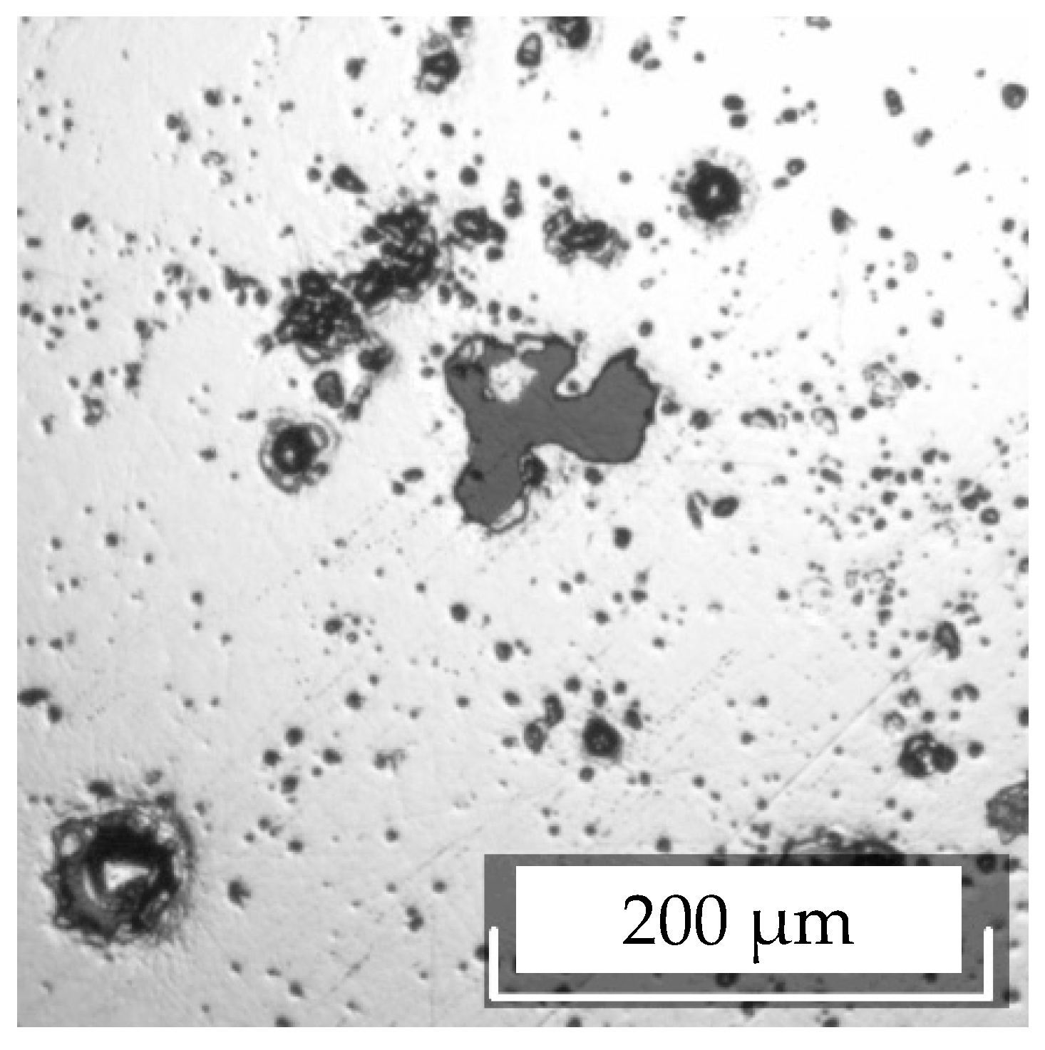
Since the ceramic (Al2O3) was not conductive prior to the experiment, the samples were coated with molybdenum using magnetron sputtering. Examination of the sample surface showed that the continuous coatings could not be obtained by this method and the pore area (non-coated molybdenum substrate surface) was on average 200 μm2 (see Figure 1).
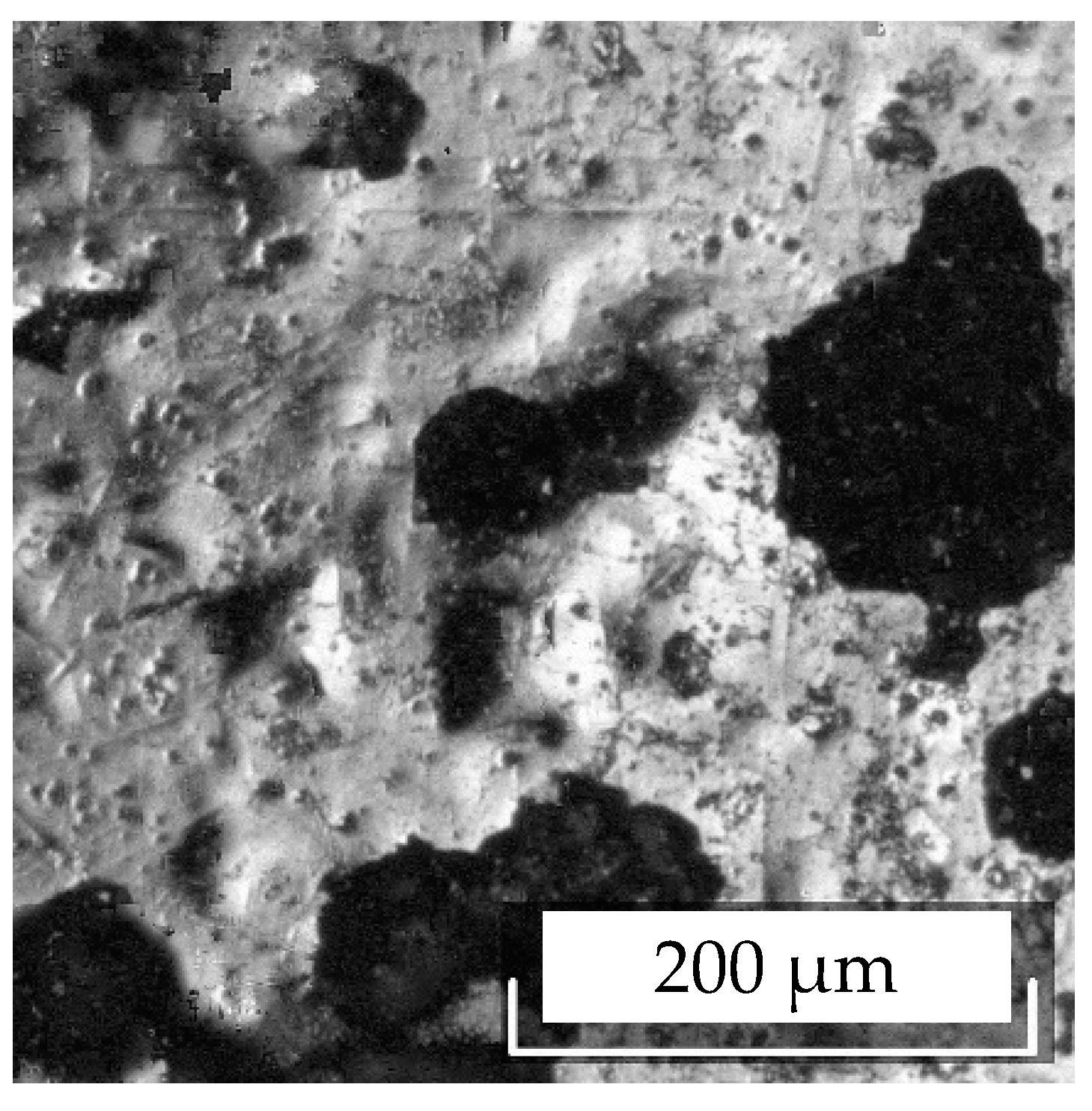
The ceramic sample with a molybdenum protective coating was placed into the NaCl–KCl–NaF (10 wt %)–K2NbF7 (8 wt %) melt in contact with Nb at a temperature of 750 °C for 10 min. Investigation of the sample surface after the experiment revealed that the average pore area increased by 27 times (see Figure 2) and X-ray analysis determined the formation of the niobium oxides of various compositions (NbO, Nb4O5, NbO2). To explain this result, the corrosion behavior of molybdenum was studied in the same melt. The molybdenum plate (Aldrich 99.9+%) was kept for 8 h in the melt and then washed, weighed, and analyzed by XRD (X-ray diffraction). No changes in the specimen weight and X-ray diffraction pattern were observed, i.e., molybdenum exhibited high corrosion resistance in the melt containing Nb(IV) complexes.
Thus, increasing the surface of the substrate non-coated by molybdenum was associated with molybdenum coating exfoliation. The reason for the exfoliation is the interaction of the melt with the substrate material to form the niobium oxides. The appearance of oxides is due to the fact that NbF62− complexes have a high affinity for oxygen and react with an oxide material to form niobium oxofluoride complexes with a higher oxidation state, (NbOF63−) [16,17]. The stabilization of the higher oxidation state of niobium was simultaneously accompanied by a decrease in the oxidation state (disproportionation reaction) with the formation of metallic niobium, which interacts with oxofluoride complexes according to the reactions:
4NbOF63− + 3Nb → 4NbO + 3NbF62− + 6F−
4NbOF63− + Nb → 2NbO2 + 3NbF62− + 6F−
Niobium oxides formed between the Al2O3 substrate and molybdenum coating during growth provide the mechanical impact on the coating, resulting in its exfoliation.
Beryllium samples with and without a molybdenum coating were tested under the same conditions as the samples of ceramics. It was found that dissolution of the substrate occurred at a high rate because its electrode potential was more negative than niobium [9].
Carbopyroceram samples were kept in the niobium-containing melt for 3 and 12 h at a temperature of 750 °C. After keeping for 3 h in the melt, the X-ray diffraction pattern of the specimen remained unchanged, and after keeping for 12 h, the formation of niobium carbide (NbC) on the carbopyroceram surface was detected by XRD.
The mechanism of the niobium carbide formation may be described as follows. Upon contact of the metallic niobium with the melt, therein a spontaneous reaction occurs (1) with the formation of the niobium reduced form. The equilibrium of Equation (1) is shifted completely to the right side [16] and niobium in the melt presents only in the form of Nb(IV) complexes. These complexes diffuse to the carbopyroceram substrate and, on its surface, are disproportionate to the niobium carbide formation and Nb(V) complexes:
5Nb(IV) + C → NbC + 4Nb(V)
The driving force of Equation (4) is the carbide formation energy ΔGNbC.
The Nb(V) complexes arising in the melt as a result of Equation (4) diffuse to niobium metal and react with it in accordance with Equation (1) to form complexes of the reduced niobium form, Nb(IV). Thus, the cycle of reactions involved in the transfer of niobium onto the carbopyroceram surface is closed, and the resulting reaction, taking into account Equations (1) and (4), can be presented as follows:
Nb + C → NbC
The extended data on corrosion tests are given in Table 1.
Hereby, based on the corrosion tests, carbopyroceram as a substrate for the electrodeposition niobium coating was chosen.
3.2. Electrochemistry of Niobium Complexes in the NaCl–KCl–NaF–K2NbF7 Melt and the Effect of Oxide Ions
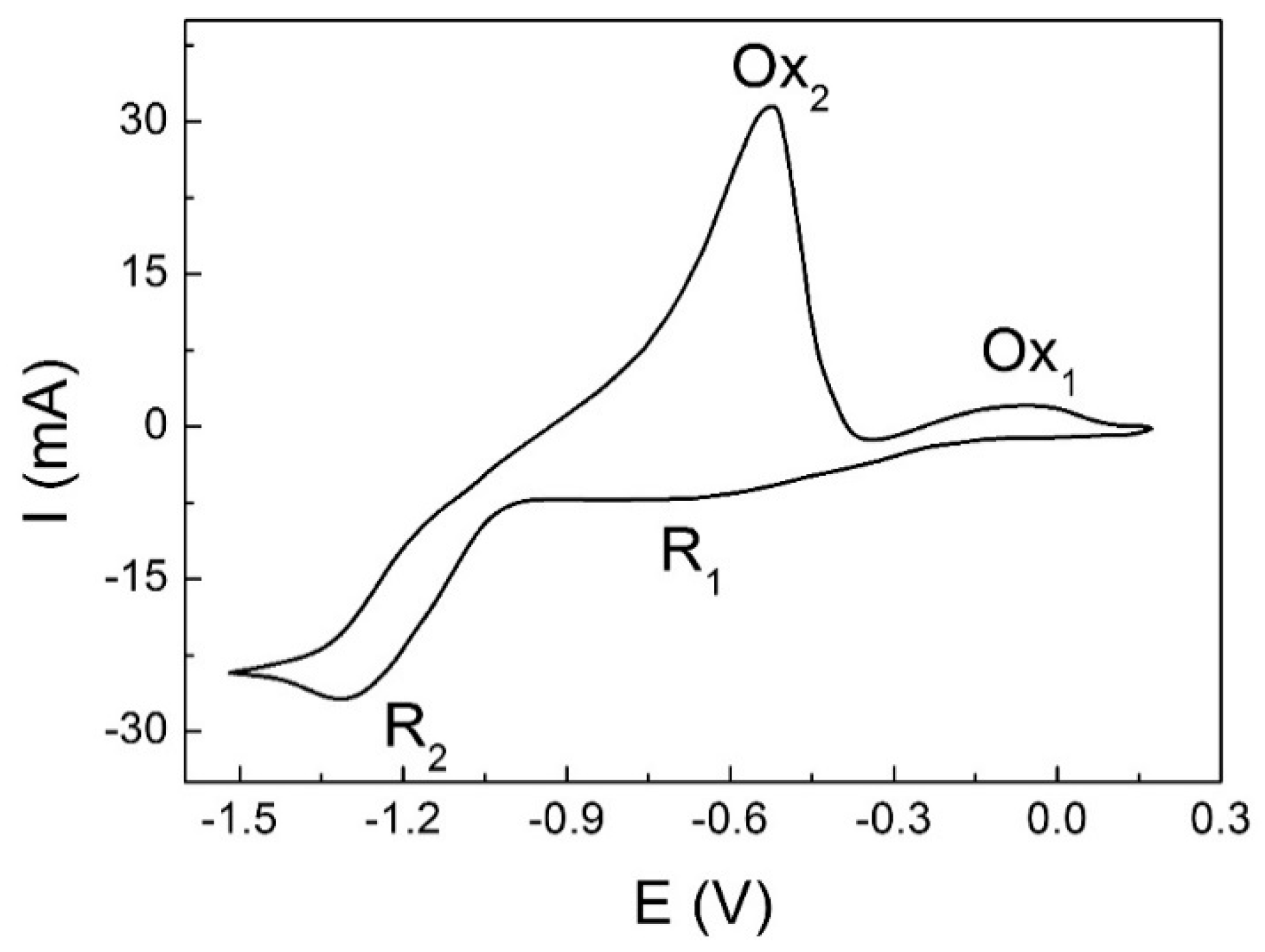
The voltammetric curve of the niobium complexes reduction in the NaCl–KCl–NaF–K2NbF7 melt obtained at a glassy-carbon electrode is presented in Figure 3.
It is characterized by two peaks R1 and R2, corresponding to the following processes [18,19,20,21]:
Nb(V) + e− → Nb(IV)
Nb(IV) + 4e− → Nb
In the anode half-cycle of the cyclic voltammetric curve, the processes of electrodeposition (Equations (6) and (7)) are matched by the processes of oxidation (Ox2, Ox1).
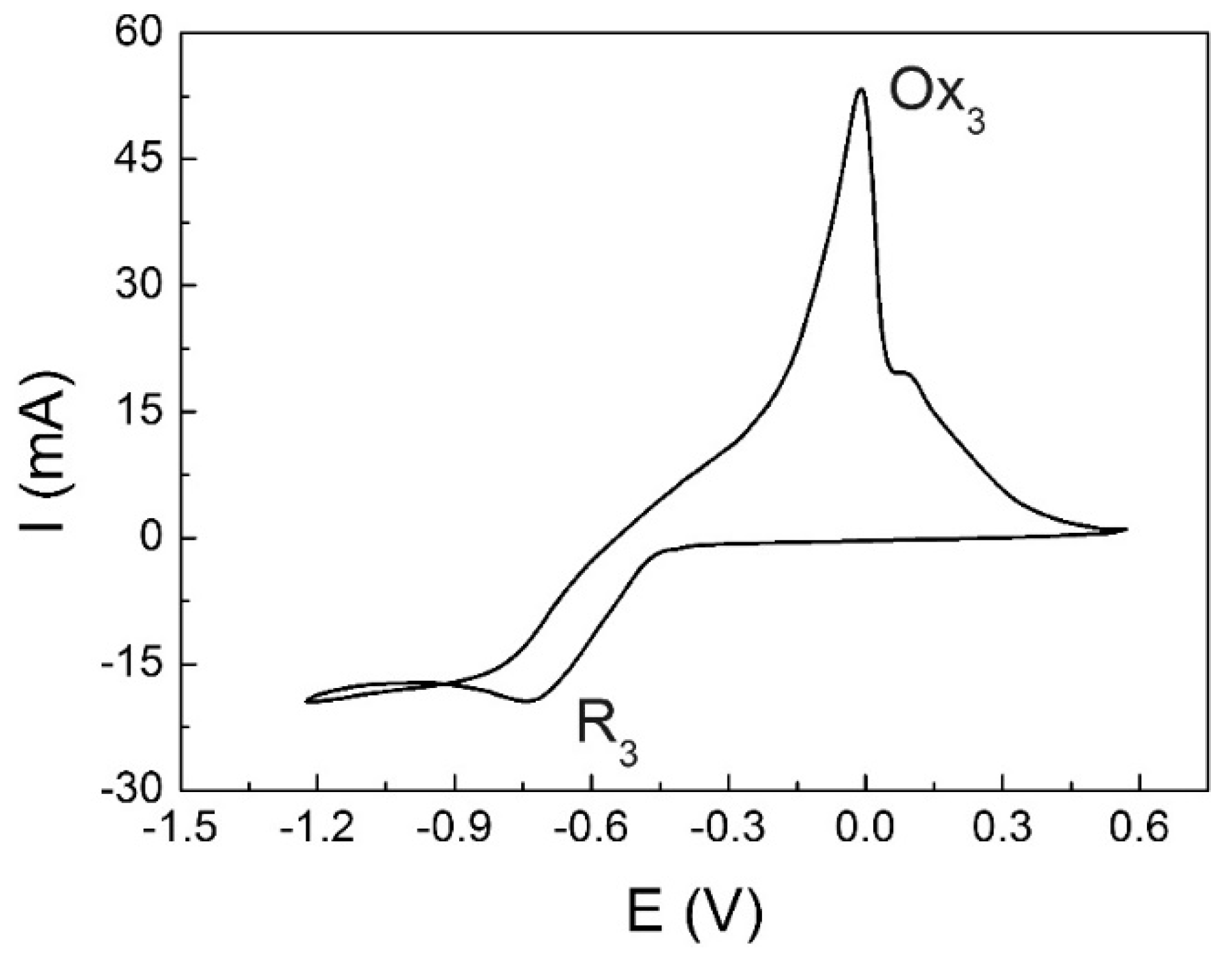
Adding small amounts of sodium oxide (Na2O) to the initial melt resulted in the emergence of wave R3 at more positive potentials than the discharge of fluoride complexes Nb(IV) (see Figure 4). At the molar ratio of O/Nb ≈ 1, the voltammogram revealed only one wave of electrodeposition, R3 (see Figure 5). This meant that wave R3 corresponded to the discharge of monoxofluoride complexes [18]:
NbOF63− + 5e− → Nb + O2− + 6F−
While (according to the XRD analysis) potentiostatic electrolysis at this wave potential resulted in the formation of oxygen–niobium solid solutions.
Thus, electrochemical experiments revealed that for obtaining pure niobium coatings, it is necessary to preclude all possible ways of the appearance of oxide ions in the melt.
3.3. Electrodeposition of Niobium Coatings on Carbopyroceram Spheres, Cathode Construction
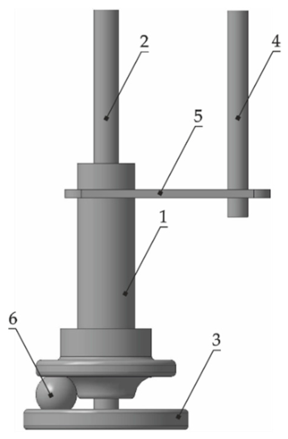
Electrodeposition of the niobium coatings on spheres 10 mm in diameter, manufactured of carbopyroceram (CPC) were carried out at a temperature of 750 °C. The anodic current density was less than 1 × 10⁻³ A·cm–2 and the cathodic current density during electrolysis was varied in the interval 5 × 10⁻³–2 × 10⁻² A·cm−2. The electrolysis time was 8–12 h. Due to the spherical shape of the substrates, a special form of the cathode should be used for plating of samples by niobium in molten salts.
In the present study, the construction of the cathode was developed (see Figure 6). The cathode had a pressing unit (1) in which a current lead (2) was located. At the end of the current lead (2) was a rigidly fixed disc electrode (3) with a rim to prevent the sphere from falling down. The fixing rod (4) was provided with a plate (5) rigidly attached with it and a pressing unit (1), which prevented the rotation of the pressing unit. The spherical sample (6) was placed between the pressing unit and disc electrode. Rotation was carried out with the aid of a stirrer with the upper drive. Construction of the cathode provided the electrical contact in a random point of the sample. Due to such contact, a uniform coating was obtained.
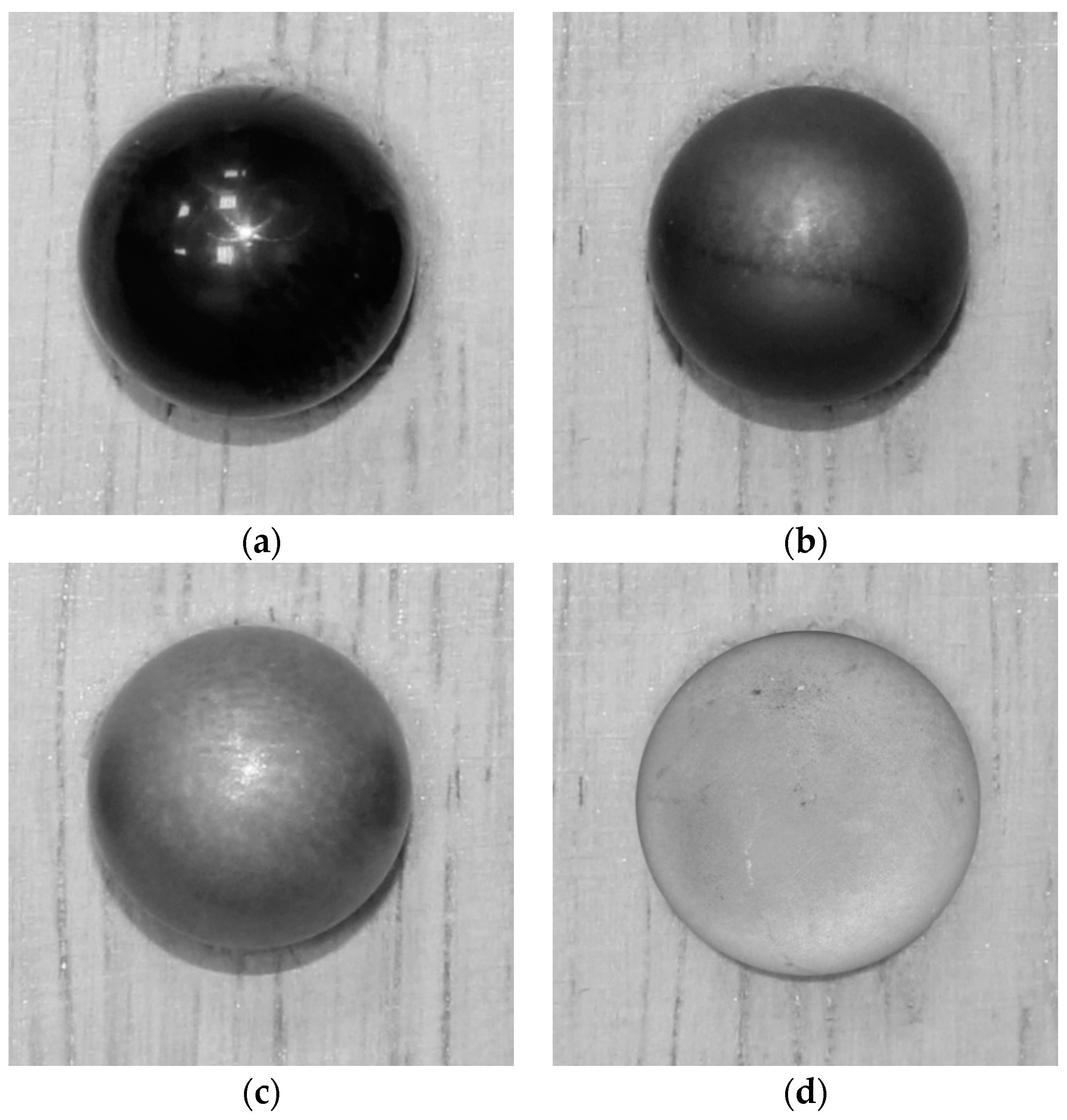
The stirrer rotation speed in all experiments was not changed and was selected to be 35 rpm. The external appearance of the specimens obtained under different electrolysis conditions is shown in Figure 7. With increasing current density, the specimen appearance changed from black lustrous for the initial CPC to light dull for CPC sample No. 3.
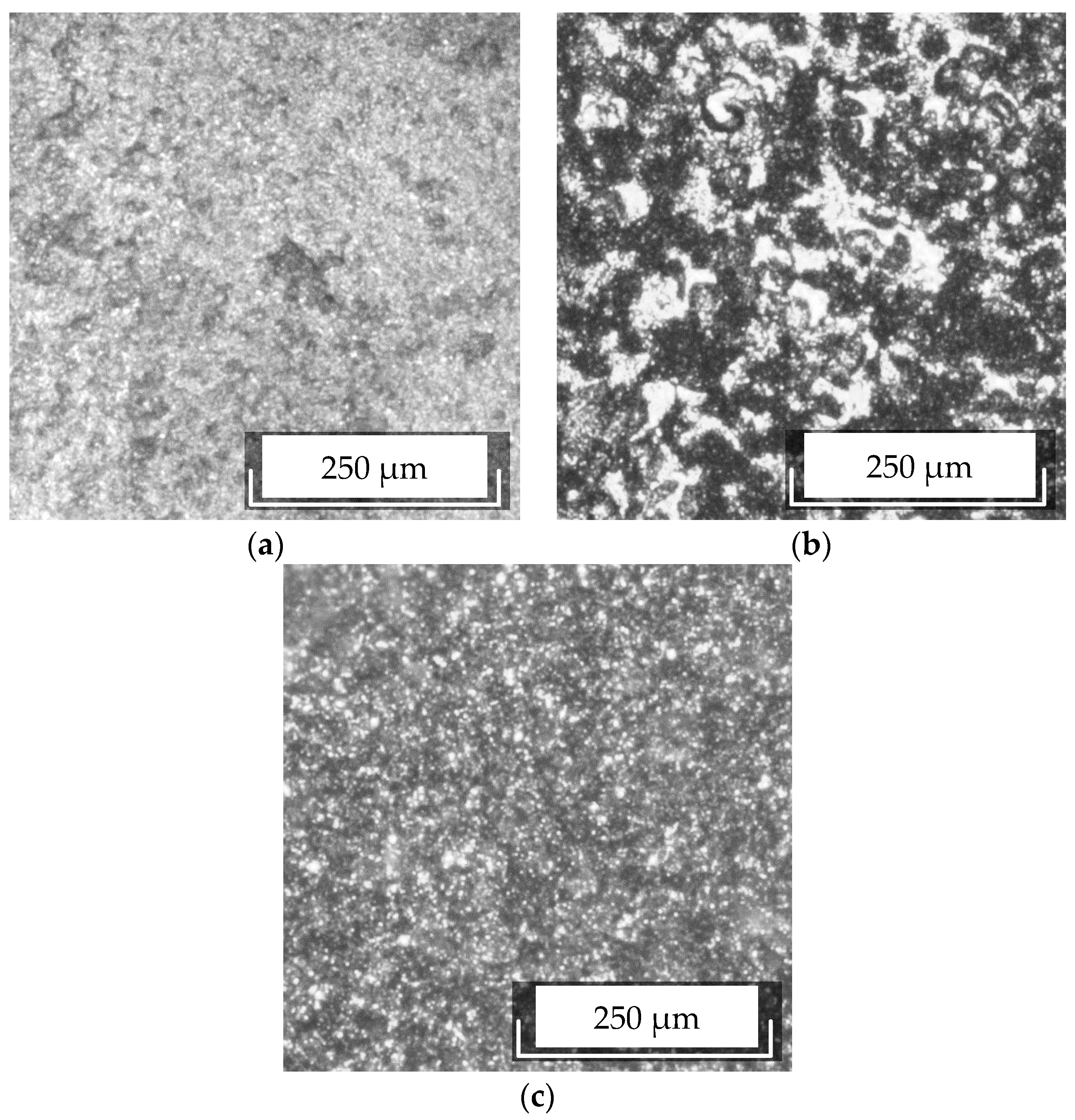
The surface of CPC specimen No. 1 obtained after electrolysis at a cathodic current density of 5 × 10⁻³ A·cm−2 is shown in Figure 8a. The surface was covered with dendritic formations of a round shape and diameter of 6 µm and more. The dendrites were distributed over the surface both as single structures and as agglomerates. These data, taking into account the external appearance of the specimen similar to that of the initial CPC, allowed a conclusion that a continuous smooth coating was not formed.
CPC specimen Nos. 2 and 3 were prepared at current densities of 1 × 10⁻² and 2 × 10⁻² A·cm−2, respectively. They differed in color (see Figure 7c,d). For example, CPC specimen No. 3 had a lighter tint than CPC specimen No. 2, which suggested a larger coating thickness as the surface of the electroplated niobium was also light gray. The difference in the color was consistent with the difference in the coating thicknesses: 40 µm for CPC No. 2 and 50 µm for CPC No. 3. Along with the color, the specimens differed in texture: the coating obtained at the higher current density was duller. Figure 8b,c illustrate the micromorphology of the surfaces of CPC specimen Nos. 2 and 3, with the more uniform structure observed in the case of CPC specimen No. 3.
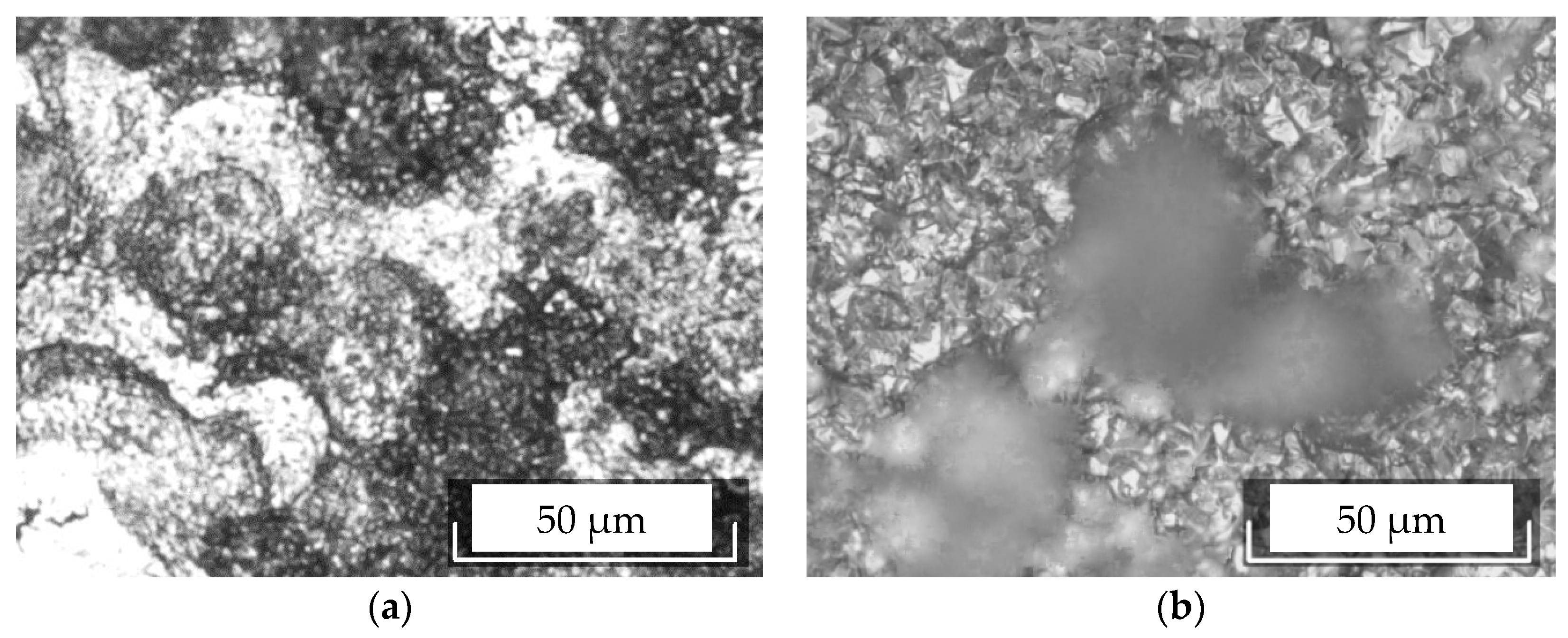
Examination of the micromorphology at higher magnification revealed an interesting essential difference between CPC specimen Nos. 2 and 3. The surface relief could be qualitatively estimated from its image. If the whole image was in the focus (see Figure 9a), the magnitude of the relief was small, whereas the presence of areas out of focus in the micrograph (see Figure 9b) suggested a large height difference, i.e., the surface was strongly developed, which was responsible for its dullness. Thus, CPC specimen No. 3 actually had a coating with a more pronounced relief when compared to CPC specimen No. 2, which was not revealed at lower magnification (see Figure 8b,c). Another important difference was the size and shape of crystallites of which the cathodic deposits consist. For example, the microstructure shown in Figure 9b (CPC sample No. 3, current density 2 × 10⁻² A·cm−2) consisted of crystallites with a relatively perfect polyhedral shape and a length of up to 10 µm. At a current density of 1 × 10⁻² A·cm−2 (CPC No. 2), the crystallites did not have a definite shape, and their size did not exceed 1 µm (see Figure 9a).
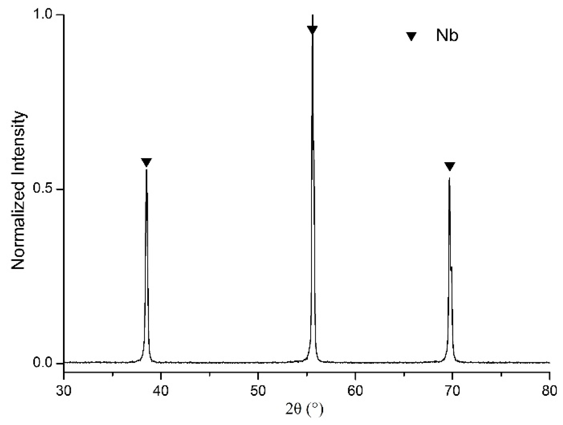
Figure 10 shows the XRD pattern of CPC No. 3 sample, which completely corresponded to the No. 89-5291 XA ASTM standard [22]. The XRD pattern indicated the structure of niobium free from stresses of various kinds (mechanical, concentration).
Thus, the boundary between the conditions ensuring the formation of coatings consisting of polyhedral crystallites and of finely dispersed crystallites without definite shape was in the interval between the current densities of 1 × 10⁻² and 2 × 10⁻² A·cm−2.
The proposed technique allows for the deposition of coatings up to 150 microns thick. It was reached by increasing the electrolysis time or numbers of electrolysis.
The main characteristics of the niobium coatings are purity, roughness (Ra, the average profile arithmetic deviation), nonsphericity (Sp), and superconductivity. Spectral quantitative analysis and gas chromatography of niobium coatings detected the following contents of impurities (ppm): Mn < 2; Mg < 3; Si < 10; Fe < 10; Ni < 5; Pb < 5; Sn < 5; Ti < 10; Al < 5; Co < 10; Mo < 10; Ca < 10; Zr < 20; V < 3; Cu ≤ 10; Cr < 5; O2 = 600; N2 < 10. The roughness of the obtained coatings was Ra = 0.4 µm and nonsphericity was Sp = 0.2 µm. The main superconducting properties of niobium coatings with the abovementioned concentration of impurities were as follows: Tc = 8.24 K, Hc1 = 1.24 Oe, and Hc2 = 3.81 Oe.
This kind of quality allows the use of a carbopyroceram substrate with a niobium coating in cryogenic devices.
4. Conclusions
The corrosion resistance of the ceramics, beryllium, and carbopyroceram was studied in the niobium containing melt. It was shown that the ceramics corroded with the formation of niobium oxides such as NbO, Nb4O5, NbO2; the beryllium samples regardless of the shape and the presence of the protective molybdenum films were dissolved in the electrolyte for the electrodeposition of niobium coatings; and carbopyroceram was not corroded in the melt. On the basis of the obtained results, carbopyroceram was chosen as a prospective material for the electrodeposition of high purity niobium coatings.
It was shown that in the NaCl–KCl–NaF–K2NbF7 melt, in the case of forming the niobium monoxofluoride complexes, they discharged at more positive potentials than the niobium(IV) fluoride complexes, and formed an oxygen–niobium solid solution.
The niobium coatings on spheres 10 mm in diameter from the carbopyroceram were obtained at 750 °C at the cathodic current density 5 × 10⁻³–2 × 10⁻² A·cm−2 and the electrolysis time 8–12 h. Influence of the cathodic current density on the microstructure of the niobium coatings was studied.
The conditions for obtaining smooth uniform high-purity superconductive niobium coatings with the thickness up to 150 µm were found.
Author Contributions
Investigation, A.D. and M.O.; Supervision, S.K.; Visualization, O.M.; Writing–original draft, A.D.; Writing–review and editing, S.K.
Conflicts of Interest
The authors declare no conflict of interest.
References
- Lam, S.K.H.; Clem, J.R.; Yang, W. A nanoscale SQUID operating at high magnetic fields. Nanotechnology 2011, 22, 455501. [Google Scholar] [CrossRef] [PubMed]
- Kolosov, V.N.; Sheverev, A.A. Deposition of superconducting Nb3Sn and high-purity Nb coatings on the rotor of a cryogenic gyroscope. Inorg. Mater. 2012, 48, 176–181. [Google Scholar] [CrossRef]
- Kolosov, V.N.; Matychenko, E.S. Evaluation of high frequency superconductivity of Niobium coatings prepared by electrodeposition process in molten salts. In Refractory Metals in Molten Salts; Kluwer: Dordrecht, The Netherlands, 1998; pp. 231–238. [Google Scholar]
- Kolosov, V.N.; Novichkov, V.Y. Zero-current deposition of superconducting Nb3Sn coatings from molten salts. Inorg. Mater. 2003, 39, 485–491. [Google Scholar] [CrossRef]
- Pana, T.J.; Chena, Y.; Zhanga, B.; Hua, J.; Li, C. Corrosion behavior of niobium coated 304 stainless steel in acid solution. Appl. Surf. Sci. 2016, 369, 320–325. [Google Scholar] [CrossRef]
- Kumar, S.; Jyothirmayi, A.; Wasekar, N.; Joshi, S.V. Influence of annealing on mechanical and electrochemical properties of cold sprayed niobium coatings. Surf. Coat. Technol. 2016, 296, 124–135. [Google Scholar] [CrossRef]
- Liu, Q.; Zhang, L.; Cheng, L.; Liu, J.; Wang, Y. Low pressure chemical vapor deposition of niobium coating on silicon carbide. Appl. Surf. Sci. 2009, 255, 8611–8615. [Google Scholar] [CrossRef]
- Liu, Q.; Zhang, L.; Cheng, L. Low pressure chemical vapor deposition of niobium coatings on graphite. Vacuum 2010, 85, 332–337. [Google Scholar] [CrossRef]
- Dubrovskiy, A.R.; Okunev, M.A.; Makarova, O.V.; Kuznetsov, S.A. Corrosion resistance of the substrates for the cryogenic gyroscope and electrodeposition of the superconductive niobium coatings. J. Phys. Conf. Ser. 2017, 857, 012008. [Google Scholar] [CrossRef] [Green Version]
- Grinevich, V.V.; Kuznetsov, S.A.; Polyakov, E.G.; Stangrit, P.T. Electrolytic production of niobium with low oxygen content. Russ. Vysokochistye Veshchestva (High-Purity Subst.) 1988, 4, 87–89. [Google Scholar]
- Koch, C.C.; Scarbrough, J.O.; Kroeger, D.M. Effects of interstitial oxygen on the superconductivity of niobium. Phys. Rev. B 1974, 9, 888–897. [Google Scholar] [CrossRef]
- Kuznetsov, S.A. Electrochemistry of refractory metals in molten salts: Application for the creation of new and functional materials. Pure Appl. Chem. 2009, 81, 1423–1439. [Google Scholar] [CrossRef]
- Dubrovskiy, A.R.; Kuznetsov, S.A. Molten salts as a promising medium for the synthesis of highly active catalytic coatings. ECS Trans. 2012, 50, 677–683. [Google Scholar] [CrossRef]
- Kuznetsov, S.A.; Gaune-Escard, M. Redox electrochemistry of europium fluoride complexes in an equimolar NaCl-KCl melt. J. Nucl. Mater. 2011, 414, 126–131. [Google Scholar] [CrossRef]
- Kuznetsov, S.A.; Kazakova, O.S.; Makarova, O.V. Electrochemical behavior and electrorefining of cobalt in NaCl—KCl—K2TiF6 melt. Z. Naturforsch. 2009, 64, 485–491. [Google Scholar]
- Kuznetsov, S.A.; Grinevitch, V.V. Niobium interaction with its chloride, fluoride, and oxofluoride complexes in melts of alkali-metal chlorides. Russ. J. Appl. Chem. 1994, 67, 1249–1255. [Google Scholar]
- Kuznetsov, S.A.; Marenkova, E.A.; Kalinnikov, V.T. Micropassivation and complexation during electrodeposition of niobium coatings. Dokl. Chem. 2015, 463, 169–173. [Google Scholar] [CrossRef]
- Kuznetsov, S.A.; Kalinnikov, V.T. Metallization of glass-ceramic technological shells and oxide materials in molten salts. Glass Phys. Chem. 2008, 34, 575–581. [Google Scholar] [CrossRef]
- Chamelot, P.; Taxil, P.; Oquab, D. Niobium electrodeposition in molten fluorides using pulsed electrolysis. J. Electrochem. Soc. 2000, 147, 4131–4137. [Google Scholar] [CrossRef]
- Polyakov, E.G.; Polyakova, L.P.; Elizarova, I.R. Cathode processes in chloride-fluoride melts containing K2NbF7. Russ. J. Electrochem. 1995, 31, 502–509. [Google Scholar]
- Kuznetsov, S.А.; Polyakov, E.G.; Stangrit, P.T. Interdiffusion in bimetallic conductors of copper-niobium and copper alloy-niobium. Russ. J. Appl. Chem. 1997, 70, 1413–1416. [Google Scholar]
- ICDD (International Centre for Diffraction Data). Database. 2002. Available online: http://www.icdd.com/ (accessed on 16 May 2018).
Figure 1.
Microstructure of ceramic sample with molybdenum protective coating before the experiment. Film thickness is approx. 1 μm.
Figure 1.
Microstructure of ceramic sample with molybdenum protective coating before the experiment. Film thickness is approx. 1 μm.

Figure 2.
Microstructure of the ceramic sample with a molybdenum protective coating after the experiment. Conditions: NaCl–KCl–NaF (10 wt %)–K2NbF7 (8 wt %) melt in contact with Nb, τ = 10 min, t = 750 °C.
Figure 2.
Microstructure of the ceramic sample with a molybdenum protective coating after the experiment. Conditions: NaCl–KCl–NaF (10 wt %)–K2NbF7 (8 wt %) melt in contact with Nb, τ = 10 min, t = 750 °C.

Figure 3.
Cyclic voltammetric curve obtained in the NaCl–KCl–NaF–K2NbF7 melt. ν = 0.1 V·s−1, t = 750 °C, CK2NbF7 = 5.05 × 10⁻⁴ mol·cm−3.
Figure 3.
Cyclic voltammetric curve obtained in the NaCl–KCl–NaF–K2NbF7 melt. ν = 0.1 V·s−1, t = 750 °C, CK2NbF7 = 5.05 × 10⁻⁴ mol·cm−3.

Figure 4.
The cyclic voltammogram obtained in the NaCl–KCl–NaF–K2NbF7 melt. ν = 0.1 V·s−1, t = 750 °C, CK2NbF7 = 5.05 × 10⁻⁴ mol·cm−3, CNa2O = 1.25 × 10⁻⁵ mol·cm−3.
Figure 4.
The cyclic voltammogram obtained in the NaCl–KCl–NaF–K2NbF7 melt. ν = 0.1 V·s−1, t = 750 °C, CK2NbF7 = 5.05 × 10⁻⁴ mol·cm−3, CNa2O = 1.25 × 10⁻⁵ mol·cm−3.
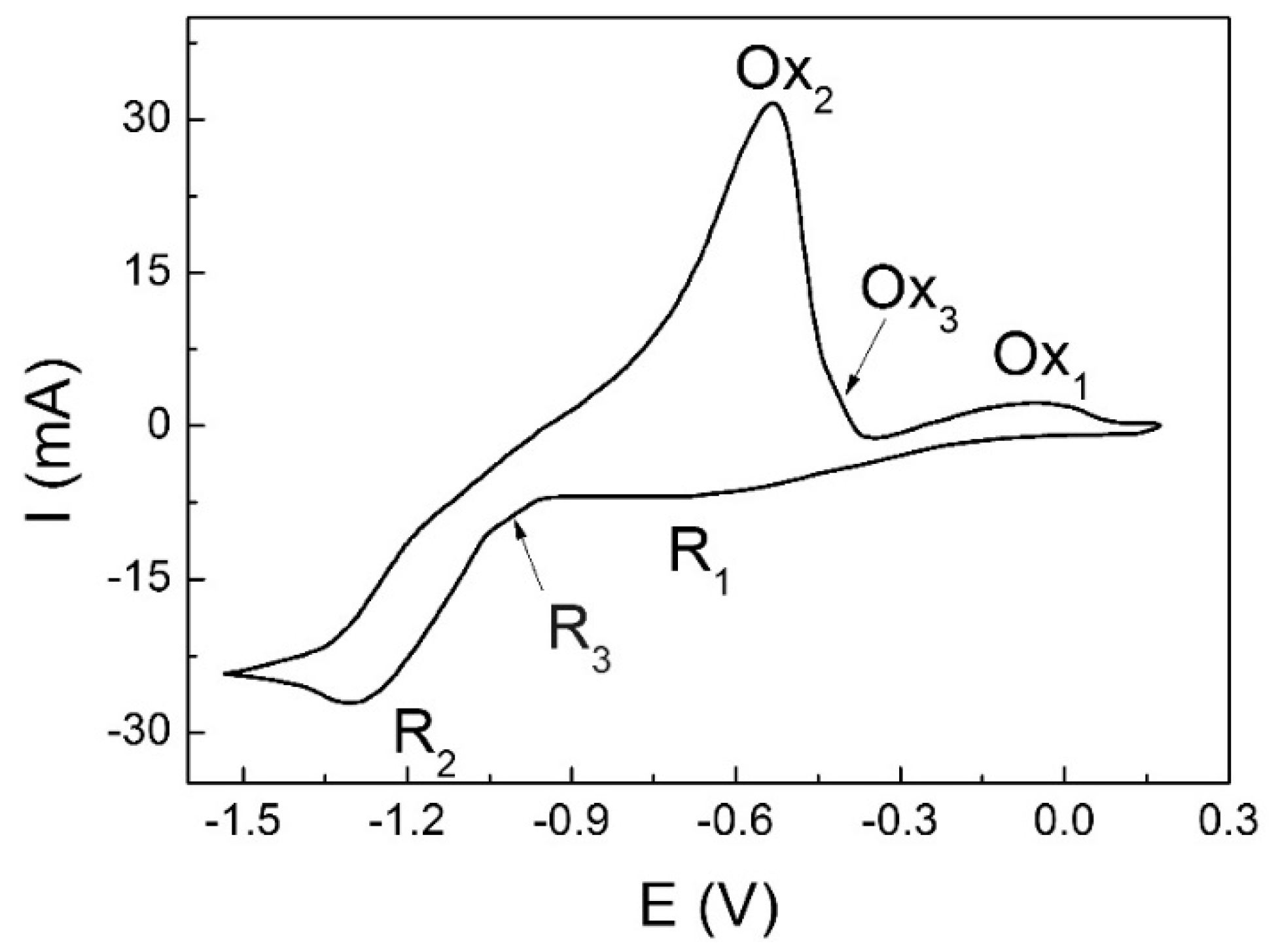
Figure 5.
The cyclic voltammogram obtained in the NaCl–KCl–NaF–K2NbF7 melt. CK2NbF7 = 5.05 × 10⁻⁴ mol·cm−3, ν = 0.1 V·s−1, t = 750 °C, C(Na2O) = 5 × 10⁻⁴ mol·cm−3.
Figure 5.
The cyclic voltammogram obtained in the NaCl–KCl–NaF–K2NbF7 melt. CK2NbF7 = 5.05 × 10⁻⁴ mol·cm−3, ν = 0.1 V·s−1, t = 750 °C, C(Na2O) = 5 × 10⁻⁴ mol·cm−3.

Figure 6.
Cathode construction for niobium coating deposition on spherical substrates. Description in the text.
Figure 6.
Cathode construction for niobium coating deposition on spherical substrates. Description in the text.

Figure 7.
Specimen view: (a) Initial CPC; (b) CPC No. 1 after electrolysis (NaCl–KCl–NaF (10 wt %)–K2NbF7 (8 wt %), i = 5 × 10⁻³ A·cm−2, τ = 8 h, t = 750 °C); (c) CPC No. 2 after electrolysis (the same melt, i = 1 × 10⁻² A·cm−2, τ = 8 h, t = 750 °C); and (d) CPC No. 3 after electrolysis (the same melt, i = 2 × 10⁻² A·cm−2, τ = 10 h, t = 750 °C).

Figure 8.
Specimen surface morphology: (a) CPC No. 1 (NaCl–KCl–NaF (10 wt %)–K2NbF7 (8 wt %), i = 5 × 10⁻³ A·cm−2, τ = 8 h, t = 750 °C); (b) CPC No. 2 (the same melt, i = 1 × 10⁻² A·cm−2, τ = 8 h, t = 750 °C); and (c) CPC No. 3 (the same melt, i = 2 × 10⁻² A cm−2, τ = 10 h, t = 750 °C).
Figure 8.
Specimen surface morphology: (a) CPC No. 1 (NaCl–KCl–NaF (10 wt %)–K2NbF7 (8 wt %), i = 5 × 10⁻³ A·cm−2, τ = 8 h, t = 750 °C); (b) CPC No. 2 (the same melt, i = 1 × 10⁻² A·cm−2, τ = 8 h, t = 750 °C); and (c) CPC No. 3 (the same melt, i = 2 × 10⁻² A cm−2, τ = 10 h, t = 750 °C).

Figure 9.
Specimen surface morphology: (a) CPC No. 2 (NaCl–KCl–NaF (10 wt %)–K2NbF7 (8 wt %), i = 1 × 10⁻² A·cm−2, τ = 8 h, t = 750 °C); (b) CPC No. 3 (the same melt, i = 2 × 10⁻² A·cm−2, τ = 10 h, t = 750 °C).
Figure 9.
Specimen surface morphology: (a) CPC No. 2 (NaCl–KCl–NaF (10 wt %)–K2NbF7 (8 wt %), i = 1 × 10⁻² A·cm−2, τ = 8 h, t = 750 °C); (b) CPC No. 3 (the same melt, i = 2 × 10⁻² A·cm−2, τ = 10 h, t = 750 °C).

Figure 10.
XRD pattern of CPC No. 3.


Table 1.
Results of corrosion tests of different shapes specimens made of different materials.
| Specimen 1 | Treatment Time | Weight Change (%)/Corrosion Rate (mg·cm−2·h−1) | XRD Data | Specimen Surface Condition |
|---|---|---|---|---|
| C Al2O3/Mo 1 µm sphere | 10 min | −0.5 | Al2O3, Mo, NbO, Nb4O5, NbO2 | Peel-off of Mo coating |
| C Al2O3/Mo 0.75 µm sphere | 10 min | −0.16 | Al2O3, Mo, NbO, Nb4O5, NbO2 | Peel-off of Mo coating |
| Al2O3 bar | 50 min | −3.5/20 | Al2O3, NbO, Nb4O5, NbO2 | Coating + dendrites |
| CPC bar | 3 h | – | – | – |
| CPC bar | 12 h | +0.42 | NbC | Coating |
| Be cylinder | 10 min | −3.2/37.5 | Be, BeO | Substrate dissolution |
| B Be/Mo 1 µm sphere | 10 min | −1.05 | Be, BeO | Peel-off of Mo coating |
1: (C)—ceramic; (B)—beryllium; Be (Al2O3)/Mo 1 µm stands for beryllium (ceramic) with 1-µm-thick molybdenum coating.
© 2018 by the authors. Licensee MDPI, Basel, Switzerland. This article is an open access article distributed under the terms and conditions of the Creative Commons Attribution (CC BY) license (http://creativecommons.org/licenses/by/4.0/).
Share and Cite
MDPI and ACS Style
Dubrovskiy, A.; Okunev, M.; Makarova, O.; Kuznetsov, S. Superconducting Niobium Coatings Deposited on Spherical Substrates in Molten Salts. Coatings 2018, 8, 213. https://doi.org/10.3390/coatings8060213
AMA Style
Dubrovskiy A, Okunev M, Makarova O, Kuznetsov S. Superconducting Niobium Coatings Deposited on Spherical Substrates in Molten Salts. Coatings. 2018; 8(6):213. https://doi.org/10.3390/coatings8060213
Chicago/Turabian StyleDubrovskiy, Anton, Maksim Okunev, Olga Makarova, and Sergey Kuznetsov. 2018. "Superconducting Niobium Coatings Deposited on Spherical Substrates in Molten Salts" Coatings 8, no. 6: 213. https://doi.org/10.3390/coatings8060213
Note that from the first issue of 2016, this journal uses article numbers instead of page numbers. See further details here.